VW Golf IV/Bora - Westfalia
VW Golf IV/Bora - Westfalia
VW Golf IV/Bora - Westfalia

Create successful ePaper yourself
Turn your PDF publications into a flip-book with our unique Google optimized e-Paper software.
....................................................................................................... 2<br />
Einbauanleitung:<br />
Elektroanlage für Anhängevorrichtung ........................................2<br />
....................................................................................................... 9<br />
Instructions de montage:<br />
Installation électrique pour dispositif d’attelage..........................9<br />
....................................................................................................... 16<br />
Installation Instructions:<br />
Electrical System for Towing Hitch...............................................16<br />
....................................................................................................... 23<br />
Istruzioni per l'installazione:<br />
Impianto elettrico per il gancio di traino.......................................23<br />
....................................................................................................... 30<br />
Inbouwinstructie:<br />
Elektrische installatie voor trekhaak.............................................30<br />
....................................................................................................... 37<br />
Návod k montáži:<br />
Elektrické zařízení pro závěsné zařízení .......................................37<br />
321 457 391 101 - 50/02
Einbauanleitung:<br />
Elektroanlage für Anhängevorrichtung<br />
Einbauanleitung:<br />
Elektroanlage für Anhängevorrichtung<br />
Allgemeine Daten<br />
Artikelnummer<br />
<strong>Westfalia</strong> Fahrzeughersteller Fahrzeug<br />
321 457 300 107 – – <strong>VW</strong> <strong>Golf</strong> <strong>IV</strong> / <strong>Bora</strong> Variant ab 05/99<br />
321 457 300 113 – – <strong>VW</strong> <strong>Golf</strong> <strong>IV</strong> / <strong>Bora</strong> Variant ab 05/99<br />
321 465 300 107 – – <strong>VW</strong> <strong>Golf</strong> <strong>IV</strong> ab 10/97 / <strong>Bora</strong> ab 11/98<br />
321 465 300 113 – – <strong>VW</strong> <strong>Golf</strong> <strong>IV</strong> ab 10/97 / <strong>Bora</strong> ab 11/98<br />
Dauerplus-Erweiterungssatz für die 13-polige Steckdose<br />
Hinweis<br />
Der Dauerplus-Erweiterungssatz ermöglicht die Inbetriebnahme einer Dauerstromversorgung<br />
und einer Ladeleitung für eine Zusatzbatterie.<br />
Artikelnummer<br />
<strong>Westfalia</strong> Fahrzeughersteller Fahrzeug<br />
300 025 300 113 – – alle Fahrzeuge<br />
2 321 457 391 101 - 50/02 <strong>VW</strong> <strong>Golf</strong> <strong>IV</strong>/<strong>Bora</strong>
Einbauanleitung:<br />
Elektroanlage für Anhängevorrichtung<br />
Wichtige Hinweise<br />
Vor Arbeitsbeginn die Einbauanleitung lesen.<br />
Der Elektroeinbausatz darf nur von qualifiziertem Fachpersonal eingebaut werden.<br />
Vorsicht - Batterie abklemmen!<br />
Beschädigung der KFZ-Elektronik, elektronisch gespeicherte Daten können verloren<br />
gehen.<br />
Vor Arbeitsbeginn den Fehlerspeicher auslesen.<br />
Vor dem Bohren sicherstellen, dass sich keine Gegenstände, wie z.B. Leitungen, hinter den<br />
Verkleidungen befinden.<br />
Blanke Karosseriestellen, wie z.B. gebohrte Löcher, entgraten und anschließend mit einem<br />
Rostschutzmittel versiegeln.<br />
Hinweis<br />
Bei der Montage auf folgende Punkte besonders achten:<br />
• Leitungen dürfen weder eingeklemmt noch beschädigt sein.<br />
• Alle Dichtungselemente ordnungsgemäß anbringen.<br />
• Die Steckdosendichtung muss auf dem Isolierschlauch positioniert werden und nicht auf<br />
den Einzeladern.<br />
• Leitungen so verlegen, dass diese weder am Fahrzeug scheuern noch abknicken.<br />
• Leitungen nicht in unmittelbarer Nähe der Abgasanlage verlegen.<br />
• Steuergeräte so anbringen, dass keine Feuchtigkeit eindringen kann. Der<br />
Kabelanschluss soll immer nach unten zeigen.<br />
Bei Anhängerbetrieb wird die Nebelschlussleuchte des Zugfahrzeugs abgeschaltet.<br />
Bei Anhängern ohne Nebelschlussleuchte muss diese nachgerüstet werden.<br />
Der Ausfall einer Blinkleuchte, auch am Anhänger, wird durch die Erhöhung der Blinkfrequenz<br />
angezeigt. Es ist keine zusätzliche Blinkkontrolle notwendig.<br />
Ein Steckdosenadapter darf nur im Anhängerbetrieb genutzt werden. Nach dem Anhängerbetrieb<br />
den Steckdosenadapter entfernen.<br />
Die Prüfung der Anhängerfunktionen mit einem Anhänger oder einem Prüfgerät mit<br />
Belastungswiderständen durchführen.<br />
Technische Änderungen vorbehalten!<br />
<strong>VW</strong> <strong>Golf</strong> <strong>IV</strong>/<strong>Bora</strong> 321 457 391 101 - 50/02 3
Einbauanleitung:<br />
Elektroanlage für Anhängevorrichtung<br />
Einbauübersicht<br />
Hinweis<br />
Der Einbau des Leitungsstranges wird am Beispiel des <strong>Golf</strong> <strong>IV</strong> Variant beschrieben. Bis auf<br />
geringfügige Abweichungen ist der Einbau bei anderen Modellen nahezu identisch.<br />
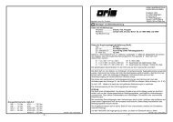
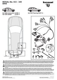
1 2 3 4 5 6 7 8 9<br />
Abb. 1: Einbauübersicht<br />
1 Dauerplus 6 Kabel-Durchführung<br />
2 Sicherungshalter 7 Anhängersteckdose<br />
3 Anhängermodul 8 rechte Rückleuchte<br />
4 Massepunkt 9 Steuerleitung für EPH<br />
5 linke Rückleuchte<br />
4 321 457 391 101 - 50/02 <strong>VW</strong> <strong>Golf</strong> <strong>IV</strong>/<strong>Bora</strong>
Einbauanleitung:<br />
Elektroanlage für Anhängevorrichtung<br />
Elektroeinbausatz einbauen<br />
1. Minusklemme der Batterie abklemmen.<br />
2. Folgende Abdeckungen und Verkleidungen entfernen:<br />
• Im Kofferraum<br />
- Abdeckung des Kofferaumbodens<br />
- Verkleidung des Heckabschlussbleches<br />
- rechte und linke Seitenverkleidung des Kofferraumes<br />
• Vom Heckabschlussblech<br />
- Abdeckung für Kabel-Durchführung auf der linken Seite<br />
3. Das Leitungsende durch die fahrzeugseitige Durchführung, ausgehend vom Kofferraum, nach<br />
außen zum Steckdosenhalteblech (Abb. 1/7) verlegen.<br />
4. Die Gummitülle aufziehen und in die Kabel-Durchführung (Abb. 1/6) einsetzen.<br />
Steckdose montieren<br />
5. Steckdosendichtung aufziehen und den Leitungsstrang gemäß der Steckdosenbelegung am<br />
Steckdosengehäuse (Abb. 1/7) anschließen und die Gummidichtung an die Steckdose<br />
heranschieben.<br />
6. Die Steckdose mit den beiliegenden Schrauben und Muttern am Halteblech (Abb. 1/7)<br />
festschrauben.<br />
Rückleuchten anschließen<br />
7. Den Stecker von der linken Rückleuchte (Abb. 1/5) abziehen und mit dem passenden<br />
Gegenstück des Leitungsstranges verbinden. Stecker muss einrasten. Den verbleibenden<br />
Stecker wieder an der Rückleuchte anbringen.<br />
8. Das Leitungsende mit den beiden 6-poligen Steckern entlang dem Heckabschlussblech zur<br />
rechten Rückleuchte (Abb. 1/8) verlegen.<br />
9. Leitung am Heckabschlussblech befestigen.<br />
10. Den Stecker von der rechten Rückleuchte (Abb. 1/8) abziehen und mit dem passenden<br />
Gegenstück des Leitungsstranges verbinden. Stecker muss einrasten. Den verbleibenden<br />
Stecker wieder an der Rückleuchte anbringen.<br />
<strong>VW</strong> <strong>Golf</strong> <strong>IV</strong>/<strong>Bora</strong> 321 457 391 101 - 50/02 5
Einbauanleitung:<br />
Elektroanlage für Anhängevorrichtung<br />
Anhängermodul anschließen<br />
11. Den 12-poligen Stecker auf das Anhängermodul aufstecken.<br />
12. Das Anhängermodul (Abb. 1/3) mit Klettband in der linken Ecke des Kofferraums befestigen.<br />
13. Die braunen Leitungen mit der Ringöse an dem fahrzeugseitigen Massepunkt (Abb. 1/4)<br />
anschließen.<br />
14. Die rote Leitung vom 12-poligen Stecker zum Sicherungshalter (Abb. 1/2) verlegen.<br />
15. Die rote Einzelleitung an einem geeigneten Dauerplusanschluss im Kofferraum bzw. am<br />
Pluspol der Batterie anschließen.<br />
Hinweis<br />
Ist ein geeigneter Dauerplus-Anschluss im Kofferraum (z.B. 12 V Steckdose) vorhanden,<br />
kann dieser genutzt werden.<br />
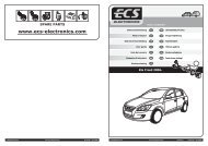
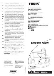
5 6<br />
1 2 3 4<br />
Abb. 2: Zusammenbau Sicherungshalter<br />
16. Die Flachsteckhülse der roten Leitung (Abb. 2/5) aus dem Leitungsstrang und der<br />
beiliegenden roten Einzelleitung (Abb. 2/4) in den Sicherungshalter einrastenden.<br />
17. Den gelben Clip (Abb. 2/6) einsetzen.<br />
18. Sicherung (Abb. 2/2) einsetzen und Abdeckung (Abb. 2/1) aufstecken.<br />
Hinweis<br />
Auf ausreichende Zugentlastung und einwandfreie Befestigung des Sicherunghalters achten.<br />
6 321 457 391 101 - 50/02 <strong>VW</strong> <strong>Golf</strong> <strong>IV</strong>/<strong>Bora</strong>
Einbauanleitung:<br />
Elektroanlage für Anhängevorrichtung<br />
Besonderheiten bei Fahrzeugen mit Einparkhilfe (EPH)<br />
Bei Fahrzeugen mit EPH besteht die Möglichkeit, die EPH bei Anhängerbetrieb inaktiv zu<br />
schalten.<br />
19. Die braun/weiße Leitung (Abb. 1/9) des Anhängermoduls zum Steuergerät der EPH verlegen<br />
und anschließen.<br />
20. Ggf. für die Inbetriebnahme, mit Hilfe des Service-Testers, das Steuergerät der EPH<br />
überprüfen und für Anhängerbetrieb umcodieren.<br />
Hinweis<br />
Bei Rückfragen bezüglich der Codierung wenden Sie sich bitte an die nächste<br />
Fachwerkstatt.<br />
Bei Nichtgebrauch der Steuerleitung, Stecker isolieren und Steuerleitung befestigen.<br />
Funktion prüfen<br />
21. Masse der Fahrzeugbatterie wieder anschließen.<br />
22. Die Anhängerfunktionen mit einem geeigneten Prüfgerät (mit Belastungswiderständen) oder<br />
mit einem Anhänger prüfen.<br />
23. Alle Leitungen mit Kabelbindern befestigen.<br />
24. Alle ausgebauten Teile wieder einbauen.<br />
<strong>VW</strong> <strong>Golf</strong> <strong>IV</strong>/<strong>Bora</strong> 321 457 391 101 - 50/02 7
Einbauanleitung:<br />
Elektroanlage für Anhängevorrichtung<br />
Steckdosenbelegung<br />
Kontakt Stromkreis Leitungsfarbe<br />
1 Blinkleuchte, links schwarz/weiß<br />
2 Nebelschlussleuchte weiß<br />
3 Masse (Stromkreis 1-8) braun<br />
4 Blinkleuchte, rechts schwarz/grün<br />
5 Rückleuchte, rechts grau/rot<br />
6 Bremsleuchte schwarz/rot<br />
7 Rückleuchte, links grau/schwarz<br />
8 Rückfahrscheinwerfer grün<br />
9 Dauerplus rot<br />
10 Ladeleitung gelb<br />
11 Masse (Stromkreis 10) braun/weiß<br />
12 Anhängerkennung --<br />
13 Masse (Stromkreis 9) braun<br />
8 321 457 391 101 - 50/02 <strong>VW</strong> <strong>Golf</strong> <strong>IV</strong>/<strong>Bora</strong>
Instructions de montage:<br />
Installation électrique pour dispositif d’attelage<br />
Instructions de montage:<br />
Installation électrique pour dispositif d’attelage<br />
Données générales<br />
Numéro d'article<br />
<strong>Westfalia</strong> Fabricant du véhicule Véhicule<br />
321 457 300 107 – – <strong>VW</strong> <strong>Golf</strong> <strong>IV</strong> / <strong>Bora</strong> Variant à partir de 05/99<br />
321 457 300 113 – – <strong>VW</strong> <strong>Golf</strong> <strong>IV</strong> / <strong>Bora</strong> Variant à partir de 05/99<br />
321 465 300 107 – – <strong>VW</strong> <strong>Golf</strong> <strong>IV</strong> à partir de 10/97 / <strong>Bora</strong> à partir<br />
de 11/98<br />
321 465 300 113 – – <strong>VW</strong> <strong>Golf</strong> <strong>IV</strong> à partir de 10/97 / <strong>Bora</strong> à partir<br />
de 11/98<br />
Module d'extension plus permanent pour la prise de courant à 13 pôles<br />
Remarque<br />
Le module d'extension plus permanent permet l'utilisation d'une alimentation en courant<br />
permanent et d'un fil de charge pour une batterie supplémentaire.<br />
Numéro d'article<br />
<strong>Westfalia</strong> Fabricant du véhicule Véhicule<br />
300 025 300 113 – – tous les véhicules<br />
<strong>VW</strong> <strong>Golf</strong> <strong>IV</strong>/<strong>Bora</strong> 321 457 391 101 - 50/02 9
Instructions de montage:<br />
Installation électrique pour dispositif d’attelage<br />
Remarques importantes<br />
Avant de commencer l'intervention, lire les instructions d'installation.<br />
L'installation du module électronique ne doit être réalisée que par des techniciens qualifiés.<br />
Attention - débrancher la batterie !<br />
Endommagement de l'électronique du véhicule, les données enregistrées<br />
électroniquement peuvent être perdues.<br />
Extraire la mémoire des erreurs avant de commencer l'intervention.<br />
Avant de commencer à percer, s'assurer que rien ne se trouve derrière le revêtement, comme<br />
des fils par exemple.<br />
Ebarber les endroits de la carrosserie qui sont polis, comme par exemple les trous alésés, puis<br />
appliquer de l'antirouille.<br />
Remarque<br />
Observer avec attention les points suivants lors du montage :<br />
• Les fils ne doivent pas être endommagés ou pincés.<br />
• Installer tous les joints dans l'ordre établi.<br />
• Le joint de la prise de courant doit être placé sur la gaine isolante et non sur un<br />
conducteur unique.<br />
• Disposer les fils de façon à ce qu'ils ne puissent pas frotter sur le véhicule ou rompre.<br />
• Ne pas placer les fils à proximité immédiate du système d'échappement.<br />
• Brancher le dispositif de commande de manière à ce que l’humidité ne puisse pas<br />
s’infiltrer. Le raccord de câbles doit toujours être dirigé vers le bas.<br />
Lors de l'utilisation de la remorque, les feux anti-brouillard arrières du véhicule tractant sont mis à<br />
l'arrêt.<br />
Pour les attelages sans feux anti-brouillard arrière, il faut en installer.<br />
Toute panne d'un clignotant, également au niveau de l'attelage, est indiquée par une<br />
augmentation de la fréquence de clignotement. Aucun dispositif de contrôle supplémentaire des<br />
clignotants n'est nécessaire.<br />
Un adaptateur de prise femelle ne doit être utilisé que pour le fonctionnement de l'attelage.<br />
Retirer cet adaptateur une fois que l'attelage n'est plus utilisé.<br />
Tester le fonctionnement de l'attelage avec un attelage ou un dispositif de contrôle avec une<br />
résistance fixe.<br />
Sous réserve de modifications techniques !<br />
10 321 457 391 101 - 50/02 <strong>VW</strong> <strong>Golf</strong> <strong>IV</strong>/<strong>Bora</strong>
Instructions de montage:<br />
Installation électrique pour dispositif d’attelage<br />
Aperçu du montage<br />
Remarque<br />
Le montage du conducteur de fils est décrit pour la <strong>Golf</strong> <strong>IV</strong> Variant. Le montage sur les<br />
autres modèles est identique, à quelques faibles différences près.<br />
1 2 3 4 5 6 7 8 9<br />
Fig. 1 : Aperçu du montage<br />
1 Plus permanent 6 Conduite du câble<br />
2 Porte-fusible 7 Adaptateur pour attelage<br />
3 Module pour attelage 8 Feu arrière droit<br />
4 Point matériel 9 Ligne pilote pour EPH<br />
5 Feu arrière gauche<br />
<strong>VW</strong> <strong>Golf</strong> <strong>IV</strong>/<strong>Bora</strong> 321 457 391 101 - 50/02 11
Instructions de montage:<br />
Installation électrique pour dispositif d’attelage<br />
Installation du module électronique<br />
1. Débrancher la borne négative de la batterie.<br />
2. Retirer les revêtements et garnitures suivants :<br />
• Dans le coffre<br />
- Revêtement du fond du coffre à bagages<br />
- Revêtement de la plaque de serrage arrière<br />
- Garniture du côté droit et gauche du coffre<br />
• De la plaque de serrage arrière<br />
- Revêtement sur le côté gauche pour la conduite du câble.<br />
3. Faire passer l'extrémité du fil via le conduit sur le côté du véhicule, en partant du coffre à<br />
bagages vers l'extérieur, jusqu'à la tôle de retenue de la prise (Fig. 1/7).<br />
4. Tirer le passe-fil en caoutchouc vers le haut et le faire passer dans le passage du câble<br />
(Fig. 1/6).<br />
Monter la prise<br />
5. Remonter le joint de la prise de courant et connecter le conducteur de fils dans le bâti de la<br />
prise (Fig. 1/7) comme indiqué au paragraphe Affectation de la prise de courant et faire<br />
glisser vers le bas le joint en caoutchouc sur la prise.<br />
6. Fixer la prise sur la plaque de retenue (Fig. 1/7) avec les vis et écrous fournis.<br />
Brancher les feux arrière<br />
7. Retirer la fiche du feu arrière gauche (Fig. 1/5) et la brancher sur la fiche adaptée du<br />
conducteur de fils. Le connecteur doit s'insérer. Rebrancher sur le feu arrière la fiche<br />
restante.<br />
8. Faire passer l'extrémité du fil avec les deux fiches à 6 pôles le long de la plaque de serrage<br />
arrière jusqu'au feu arrière droit (Fig. 1/8).<br />
9. Fixer le fil sur la plaque de serrage arrière.<br />
10. Retirer la fiche du feu arrière droit (Fig. 1/8) et la brancher sur la fiche adaptée du conducteur<br />
de fils. Le connecteur doit s'insérer. Rebrancher sur le feu arrière la fiche restante.<br />
12 321 457 391 101 - 50/02 <strong>VW</strong> <strong>Golf</strong> <strong>IV</strong>/<strong>Bora</strong>
Instructions de montage:<br />
Installation électrique pour dispositif d’attelage<br />
Raccorder le module pour attelage<br />
11. Mettre la fiche à 12 pôles sur le module pour attelage.<br />
12. Fixer le module pour remorque (Fig. 1/3) avec une bande velcro sur le coin gauche du coffre<br />
à bagages.<br />
13. Raccorder les fils marron avec des anneaux sur le point matériel du côté du véhicule<br />
(Fig. 1/4).<br />
14. Placer le fil rouge de la fiche à 12 pôles sur le porte-fusible (Fig. 1/2).<br />
15. Connecter le fil rouge unique sur la connexion du plus permanent correspondante dans le<br />
coffre ou sur le pôle positif de la batterie.<br />
Remarque<br />
Si une connexion du plus permanent adéquate est disponible dans le coffre (par ex. une<br />
prise 12 V), il est possible de l'utiliser.<br />
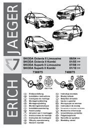
5 6<br />
1 2 3 4<br />
Fig. 2 : Montage du porte-fusible<br />
16. Insérer le contact femelle du fil rouge (Fig. 2/5) du conducteur de fils et du fil rouge joint (Fig.<br />
2/4) dans le porte-fusible.<br />
17. Mettre en place le clip jaune (Fig. 2/6).<br />
18. Installer le fusible (Fig. 2/2) et remettre le revêtement (Fig. 2/1) en place.<br />
Remarque<br />
Vérifier que la décharge de traction est suffisante et que le porte-fusible est correctement<br />
fixé.<br />
<strong>VW</strong> <strong>Golf</strong> <strong>IV</strong>/<strong>Bora</strong> 321 457 391 101 - 50/02 13
Instructions de montage:<br />
Installation électrique pour dispositif d’attelage<br />
Particularités pour les véhicules équipés d'un système d'aide au stationnement (EPH)<br />
Pour les véhicules équipés d'un système EPH, il est possible de désactiver le système EPH lors<br />
de l'utilisation de la remorque.<br />
19. Relier et connecter le fil marron/blanc (Fig. 1/9) du module de l'attelage sur le dispositif de<br />
commande de l'EPH.<br />
20. Le cas échéant, vérifier le dispositif de commande EPH avant la mise en marche avec l'aide<br />
d'un technicien-testeur du service après-vente afin de modifier le code pour une utilisation de<br />
l'attelage.<br />
Remarque<br />
Pour toute question relative à la programmation, adressez-vous à l'atelier le plus proche de<br />
chez vous.<br />
Si vous n'utilisez pas la ligne pilote, isoler la fiche et fixe la ligne pilote.<br />
Vérifier le fonctionnement<br />
21. Reconnecter la masse de la batterie du véhicule.<br />
22. Vérifier le fonctionnement de l'attelage avec un dispositif de contrôle adéquat (avec<br />
résistance fixe) ou avec un attelage.<br />
23. Fixer tous les fils avec des attaches-câbles.<br />
24. Remonter toutes les pièces qui ont été démontées.<br />
14 321 457 391 101 - 50/02 <strong>VW</strong> <strong>Golf</strong> <strong>IV</strong>/<strong>Bora</strong>
Instructions de montage:<br />
Installation électrique pour dispositif d’attelage<br />
Affectation de la prise de courant<br />
Contact Circuit Couleur du fil<br />
1 Clignotant, gauche noir/blanc<br />
2 Feux anti-brouillard blanc<br />
3 Masse (circuit 1-8) marron<br />
4 Clignotant, droit noir/vert<br />
5 Feu arrière, droit gris/rouge<br />
6 Feu stop noir/rouge<br />
7 Feu arrière, gauche gris/noir<br />
8 Feu marche-arrière vert<br />
9 Plus permanent rouge<br />
10 Fil de charge jaune<br />
11 Masse (circuit 10) marron/blanc<br />
12 Identification attelage --<br />
13 Masse (circuit 9) marron<br />
<strong>VW</strong> <strong>Golf</strong> <strong>IV</strong>/<strong>Bora</strong> 321 457 391 101 - 50/02 15
Installation Instructions:<br />
Electrical System for Towing Hitch<br />
Installation Instructions:<br />
Electrical System for Towing Hitch<br />
General Data<br />
Part Number<br />
<strong>Westfalia</strong> Vehicle Manufacturer Vehicle<br />
321 457 300 107 – – <strong>VW</strong> Gold <strong>IV</strong> / <strong>Bora</strong> Variant as of 05/99<br />
321 457 300 113 – – <strong>VW</strong> Gold <strong>IV</strong> / <strong>Bora</strong> Variant as of 05/99<br />
321 465 300 107 – – <strong>VW</strong> Gold <strong>IV</strong> as of 10/97 / <strong>Bora</strong> as of 11/98<br />
321 465 300 113 – – <strong>VW</strong> Gold <strong>IV</strong> as of 10/97 / <strong>Bora</strong> as of 11/98<br />
Constant plus extension kit for the 13-pin socket<br />
Note<br />
The constant plus extension kit allows a permanent power supply and a charging lead for a<br />
booster battery to be used.<br />
Part Number<br />
<strong>Westfalia</strong> Vehicle Manufacturer Vehicle<br />
300 025 300 113 – – all vehicles<br />
16 321 457 391 101 - 50/02 <strong>VW</strong> <strong>Golf</strong> <strong>IV</strong>/<strong>Bora</strong>
Installation Instructions:<br />
Electrical System for Towing Hitch<br />
Important Notes<br />
Read the installation manual prior to starting work.<br />
The electrical kit should only be installed by qualified personnel.<br />
Caution – Disconnect the battery!<br />
Danger of damage to the vehicle’s electronic system. Data which are stored<br />
electronically may get lost.<br />
Read out the fault storage prior to starting work.<br />
Make sure prior to drilling that no objects like, for example, cables are located behind the covers.<br />
Deburr any bare body parts, like bore holes, and seal them with the help of some rust inhibitor.<br />
Note<br />
During installation special attention has to be paid to the following points:<br />
• Cables must not be pinched or damaged.<br />
• All sealing elements have to be installed properly.<br />
• The socket gasket has to be positioned on the insulating sleeve and not on the individual<br />
wires.<br />
• Lay the cables such that they do not rub on the vehicle and are not bent.<br />
• Do not lay any cables near the exhaust system.<br />
• Install the controller such that it is protected against the ingress of humidity. The cable<br />
connection should always face downward.<br />
When a trailer is used, the rear fog lamp of the traction vehicle is deactivated.<br />
In the case of trailers without rear fog lamp, a rear fog lamp has to be retrofitted.<br />
When a direction indicator lamp fails, also on the trailer, this is indicated by a higher flashing<br />
frequency. No additional direction indicator check is necessary.<br />
A socket adapter may only be used in conjunction with a trailer. When the trailer is no longer<br />
used, remove the socket adapter.<br />
Correct trailer operation has to be checked using a trailer or a test instrument with load resistors.<br />
Subject to technical alterations!<br />
<strong>VW</strong> <strong>Golf</strong> <strong>IV</strong>/<strong>Bora</strong> 321 457 391 101 - 50/02 17
Installation Instructions:<br />
Electrical System for Towing Hitch<br />
Installation Overview<br />
Note<br />
The installation of the cable harness is described on the basis of the example of the <strong>Golf</strong> <strong>IV</strong><br />
Variant. Except for some slight deviations, the installation procedure is nearly the same for all<br />
other models.<br />
1 2 3 4 5 6 7 8 9<br />
Fig. 1: Installation Overview<br />
1 Constant plus 6 Cable leadthrough<br />
2 Fuse holder 7 Trailer socket<br />
3 Trailer module 8 Right tail light<br />
4 Ground point 9 PDC control line<br />
5 Left tail light<br />
18 321 457 391 101 - 50/02 <strong>VW</strong> <strong>Golf</strong> <strong>IV</strong>/<strong>Bora</strong>
Installation Instructions:<br />
Electrical System for Towing Hitch<br />
Installing the electrical kit<br />
1. Disconnect the negative battery terminal.<br />
2. Remove the following coverings:<br />
• In the luggage trunk<br />
- Covering of luggage trunk bottom<br />
- Covering of the rear end plate<br />
- Right-hand and left-hand side covering of the luggage trunk<br />
• From the rear end plate<br />
- Covering for the cable leadthrough on the left-hand side<br />
3. Starting in the luggage trunk, lead the cable end through the vehicle’s cable leadthrough to<br />
the outside up to the socket holder plate (Fig. 1/7).<br />
4. Fit the rubber grommet and insert it into the cable leadthrough (Fig. 1/6).<br />
Socket installation<br />
5. Fit the socket gasket and connect the cable harness to the socket housing in accordance with<br />
the pin assignment plan (Fig. 1/7) and push the rubber grommet against the socket.<br />
6. Screw the socket onto the holding plate (Fig. 1/7) using the supplied screws and nuts.<br />
Connecting the tail lights<br />
7. Unplug the plug of the left-hand tail light (Fig. 1/5) and connect it to its counterpart on the<br />
cable harness. Make sure that the plug locks firmly into place. Plug the residual plug back into<br />
the tail light.<br />
8. Lay the cable end with the two 6-pin plugs along the rear end plate to the right-hand tail light<br />
(Fig. 1/8).<br />
9. Secure the cable on the rear end plate.<br />
10. Unplug the plug of the right-hand tail light (Fig. 1/8) and connect it to its counterpart on the<br />
cable harness. Make sure that the plug locks firmly into place. Plug the residual plug back into<br />
the tail light.<br />
<strong>VW</strong> <strong>Golf</strong> <strong>IV</strong>/<strong>Bora</strong> 321 457 391 101 - 50/02 19
Installation Instructions:<br />
Electrical System for Towing Hitch<br />
Connecting the trailer module<br />
11. Plug the 12-pin plug into the trailer module.<br />
12. Fasten the trailer module (Fig. 1/3) to the left-hand side of the luggage trunk using some<br />
velcro tape.<br />
13. Connect the brown wires with the eyelet to the vehicle’s ground point (Fig. 1/4).<br />
14. Lay the red cable from the 12-pin plug to the fuse holder (Fig. 1/2).<br />
15. Connect the individual red cable to a suitable constant plus connector in the luggage trunk or<br />
to the battery’s positive terminal.<br />
Note<br />
If there is a suitable constant plus connector available in the luggage trunk (e.g. a 12 V<br />
power socket), this connector can be used.<br />
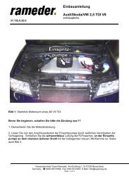
5 6<br />
Fig. 2: Fuse holder assembly<br />
1 2 3 4<br />
16. Let the quick-connect receptacle of the red cable (Fig. 2/5) of the cable harness and the one<br />
of the supplied single red cable (Fig. 2/4) lock into place in the fuse holder.<br />
17. Fit the yellow clip (Fig. 2/6).<br />
18. Insert the fuse (Fig. 2/2) and fit the cover (Fig. 2/1).<br />
Note<br />
Ensure sufficient strain relief and correct installation of the fuse holder.<br />
20 321 457 391 101 - 50/02 <strong>VW</strong> <strong>Golf</strong> <strong>IV</strong>/<strong>Bora</strong>
Installation Instructions:<br />
Electrical System for Towing Hitch<br />
Special information concerning vehicles with parking distance control (PDC)<br />
On vehicles with PDC it is possible to deactivate the PDC for trailer operation.<br />
19. Lay the brown/white cable (Fig. 1/9) of the trailer module to the PDC controller and connect it.<br />
20. If necessary, check the PDC controller using the Service Tester and recode it for trailer<br />
operation.<br />
Note<br />
If you have any queries concerning the coding procedure, please contact the nearest garage.<br />
If the control line is not used, insulate the connectors and secure the control line.<br />
Checking correct operation<br />
21. Reconnect the ground of the vehicle’s battery.<br />
22. Check the trailer function with the help of a suitable test instrument (with load resistors) or<br />
with the help of a trailer.<br />
23. Secure all cables using cable ties.<br />
24. Refit any parts removed for installation.<br />
<strong>VW</strong> <strong>Golf</strong> <strong>IV</strong>/<strong>Bora</strong> 321 457 391 101 - 50/02 21
Installation Instructions:<br />
Electrical System for Towing Hitch<br />
Socket Pin Assignment<br />
Pin Circuit Wire Colour<br />
1 Indicator lamp, left-hand side black/white<br />
2 Rear fog lamp white<br />
3 Ground (circuit 1-8) brown<br />
4 Indicator lamp, right-hand side black/green<br />
5 Tail light, right-hand side gray/red<br />
6 Stop lamp black/red<br />
7 Tail light, left-hand side gray/black<br />
8 Back-up light green<br />
9 Constant plus red<br />
10 Charging line yellow<br />
11 Ground (circuit 10) brown/white<br />
12 Trailer identification --<br />
13 Ground (circuit 9) brown<br />
22 321 457 391 101 - 50/02 <strong>VW</strong> <strong>Golf</strong> <strong>IV</strong>/<strong>Bora</strong>
Istruzioni per l'installazione:<br />
Impianto elettrico per il gancio di traino<br />
Istruzioni per l'installazione:<br />
Impianto elettrico per il gancio di traino<br />
Dati in generale<br />
Codice articolo<br />
<strong>Westfalia</strong> Costruttore veicolo Veicolo<br />
321 457 300 107 – – <strong>VW</strong> <strong>Golf</strong> <strong>IV</strong> / <strong>Bora</strong> Variant dal 05/99<br />
321 457 300 113 – – <strong>VW</strong> <strong>Golf</strong> <strong>IV</strong> / <strong>Bora</strong> Variant dal 05/99<br />
321 465 300 107 – – <strong>VW</strong> <strong>Golf</strong> <strong>IV</strong> dal 10/97 / <strong>Bora</strong> dal 11/98<br />
321 465 300 113 – – <strong>VW</strong> <strong>Golf</strong> <strong>IV</strong> dal 10/97 / <strong>Bora</strong> dal 11/98<br />
kit ampliamento del positivo permanente per presa a 13 poli<br />
Nota<br />
Il kit ampliamento del positivo permanente permette la messa in funzione dell'alimentazione<br />
della corrente continua e del circuito di carica per una batteria aggiuntiva.<br />
Codice articolo<br />
<strong>Westfalia</strong> Costruttore veicolo Veicolo<br />
300 025 300 113 – – tutti i veicoli<br />
<strong>VW</strong> <strong>Golf</strong> <strong>IV</strong>/<strong>Bora</strong> 321 457 391 101 - 50/02 23
Istruzioni per l'installazione:<br />
Impianto elettrico per il gancio di traino<br />
Note importanti<br />
Prima di iniziare i lavori, leggere le istruzioni di montaggio.<br />
Il kit elettrico deve essere montato solo da personale qualificato.<br />
Attenzione - Staccare la batteria!<br />
Danni all'elettronica del veicolo, i dati memorizzati possono essere persi.<br />
Prima di iniziare consultare la memoria degli errori.<br />
Prima di forare assicurarsi che dietro al rivestimento non ci siano oggetti, come per es. cablaggi.<br />
Togliere dai punti di carrozzeria nudi, come per es. dai bordi dei fori la bava e proteggerli con<br />
dell'antiruggine.<br />
Nota<br />
Durante il montaggio prestare molta attenzione a quanto segue:<br />
• I cavi non devono essere bloccati o danneggiati.<br />
• Posizionare tutte le guarnizioni a regola d'arte.<br />
• La guarnizione della presa deve essere posizionata sulla guaina isolante e non sui singoli<br />
fili.<br />
• Posare i cablaggi in modo tale, che non sfreghino contro il veicolo e non risultino piegati.<br />
• Non posare i cablaggi nelle immediate vicinanze dell'impianto gas di scarico.<br />
• Montare le centraline in modo tale che non possa entrare umidità. Il collegamento del<br />
cavo deve essere sempre rivolto verso il basso.<br />
In caso di funzionamento con rimorchio viene spenta la luce fendinebbia del veicolo.<br />
In caso di rimorchi non corredati di luce fendinebbia, questa dovrà essere prevista.<br />
Il guasto al lampeggiante direzionale, viene indicato anche al rimorchio con l'aumento<br />
dell'intermittenza. Non è necessario altro dispositivo di controllo del lampeggio.<br />
La presa adattatore può essere impiegata solo in presenza del rimorchio. Staccando il rimorchio<br />
togliere anche la presa adattatore.<br />
Verificare le funzioni con il rimorchio stesso oppure un dispositivo di misurazione con resistenze<br />
di carico.<br />
Con riserva di modifiche tecniche!<br />
24 321 457 391 101 - 50/02 <strong>VW</strong> <strong>Golf</strong> <strong>IV</strong>/<strong>Bora</strong>
Istruzioni per l'installazione:<br />
Impianto elettrico per il gancio di traino<br />
Schema di montaggio<br />
Nota<br />
La posa del fascio di cavi viene descritto prendendo l'esempio della <strong>Golf</strong> <strong>IV</strong> Variant . Salvo<br />
lievi differenze la posa per altri modelli è pressoché identica.<br />
1 2 3 4 5 6 7 8 9<br />
Fig. 1 : Schema di montaggio<br />
1 Positivo permanente 6 Passaggio cavi<br />
2 Portafusibili 7 Presa rimorchio<br />
3 Modulo rimorchio 8 Luce di posizione posteriore destra<br />
4 Massa 9 Cavo di comando EPH<br />
5 Luce di posizione posteriore sinistra<br />
<strong>VW</strong> <strong>Golf</strong> <strong>IV</strong>/<strong>Bora</strong> 321 457 391 101 - 50/02 25
Istruzioni per l'installazione:<br />
Impianto elettrico per il gancio di traino<br />
Montaggio kit elettrico<br />
1. Staccare il morsetto negativo dalla batteria.<br />
2. Togliere le seguenti coperture e rivestimenti:<br />
• Nel bagagliaio<br />
- La copertura del pianale di carico<br />
- Il rivestimento della lamiera posteriore<br />
- Rivestimento laterale sinistro e destro del bagagliaio<br />
• Dalla lamiera posteriore<br />
- Copertura per il passaggio cavi sul lato sinistro<br />
3. Infilare il terminale del fascio di cavi attraverso l'apposita apertura, partendo dal bagagliaio,<br />
verso l'esterno sino alla lamiera portapresa (fig.1/7).<br />
4. Infilare la bussola di gomma nel passaggio cavi (fig. 1/6).<br />
Montare la presa<br />
5. Inserire la guarnizione della presa e collegare il fascio di cavi come da schema occupazione<br />
presa (fig.1/7) ed avvicinare la guarnizione di gomma alla presa.<br />
6. Fissare la presa al supporto (fig. 1/7) mediante le viti ed i dadi forniti.<br />
Collegamento delle luci di posizione posteriori<br />
7. Togliere la spina dalla luce di posizione posteriore sinistra (fig. 1/5) e collegarla alla relativa<br />
controparte adatta del fascio di cavi. La spina deve scattare. Inserire lo spinotto rimanente<br />
alla luce di posizione posteriore.<br />
8. Posare il terminale del cavo corredato delle due spine a 6 poli lungo la lamiera posteriore in<br />
direzione della luce di posizione posteriore destra (fig. 1/8).<br />
9. Fissare il cavo alla lamiera posteriore.<br />
10. Togliere la spina dalla luce di posizione posteriore destra (fig. 1/8) e collegarla alla relativa<br />
controparte adatta del fascio di cavi. La spina deve scattare. Inserire lo spinotto rimanente<br />
alla luce di posizione posteriore.<br />
26 321 457 391 101 - 50/02 <strong>VW</strong> <strong>Golf</strong> <strong>IV</strong>/<strong>Bora</strong>
Istruzioni per l'installazione:<br />
Impianto elettrico per il gancio di traino<br />
Collegare il modulo del rimorchio<br />
11. Inserire lo spinotto a 12 poli su detto modulo.<br />
12. Fissare il modulo del rimorchio (fig. 1/3) con l'apposito nastro all'angolo sinistro del vano<br />
portabagagli.<br />
13. Collegare i cavi marroni corredati degli occhielli alla massa del veicolo (fig. 1/4).<br />
14. Posare il cavo rosso dallo spinotto a 12 poli al portafusibili (fig. 1/2).<br />
15. Collegare il singolo cavo roso con una connessione adatta del positivo permanente e/o al<br />
polo positivo della batteria.<br />
Nota<br />
Se nel bagagliaio è presente un collegamento del positivo permanente adatto (per.es. presa<br />
12V), si potrà usufruire di questo punto.<br />
5 6<br />
1 2 3 4<br />
Fig. 2 : Montaggio portafusibili<br />
16. Inserire la spina piatta del cavo rosso (fig. 2/5) del fascio di cavi ed il cavo singolo rosso (fig.<br />
2/4) al portafusibili.<br />
17. Inserire il clip giallo (fig. 2/6).<br />
18. Inserire il fusibile (fig. 2/2) e posizionare il coperchio (fig. 2/1).<br />
Nota<br />
Prestare attenzione allo scarico della trazione e fissaggio idoneo del portafusibile.<br />
<strong>VW</strong> <strong>Golf</strong> <strong>IV</strong>/<strong>Bora</strong> 321 457 391 101 - 50/02 27
Istruzioni per l'installazione:<br />
Impianto elettrico per il gancio di traino<br />
Particolarità per veicoli corredati di aiuto al parcheggio (EPH)<br />
In caso di veicoli con EPH esiste la possibilità di escludere la EPH in caso di impiego di rimorchi.<br />
19. Posare il cavo marrone/bianco (fig. 1/9) del modulo di traino alla centralina del EPH e<br />
collegarlo.<br />
20. Ev. per la messa in funzione, con l'ausilio di un tester, verificare la centralina dell'EPH e<br />
cambiare ed eseguire una nuova codifica per il funzionamento con gancio di traino.<br />
Nota<br />
Per eventuali ulteriori informazioni relative alla codifica Vi preghiamo di contattare il servizio<br />
assistenza più vicino.<br />
In caso di non uso del cavo di comando, isolare la spina e fissare il cavo di comando.<br />
Verificare il funzionamento<br />
21. Ricollegare la massa della batteria del veicolo.<br />
22. Verificare il funzionamento del rimorchio mediante dispositivo idoneo (con resistenze di<br />
carico) o collegando il rimorchio stesso.<br />
23. Fissare tutti i cavi con fascette stringicavo.<br />
24. Rimontare tutte le parti smontate precedentemente.<br />
28 321 457 391 101 - 50/02 <strong>VW</strong> <strong>Golf</strong> <strong>IV</strong>/<strong>Bora</strong>
Istruzioni per l'installazione:<br />
Impianto elettrico per il gancio di traino<br />
Occupazione presa<br />
Contatto Circuito elettrico Colore cavo<br />
1 Luce direzionale sinistra nero/bianco<br />
2 Fendinebbia bianco<br />
3 Massa (circuito elettrico 1-8) marrone<br />
4 Luce direzionale destra nero/verde<br />
5 Luce di posizione posteriore destra grigio/rosso<br />
6 Luce di arresto nero/rosso<br />
7 Luce di posizione posteriore sinistra grigio/nero<br />
8 Luce di retromarcia verde<br />
9 Positivo permanente rosso<br />
10 Cavo di carica giallo<br />
11 Massa (circuito elettrico 10) marrone/bianco<br />
12 Rilevamento rimorchio --<br />
13 Massa (circuito elettrico 9) marrone<br />
<strong>VW</strong> <strong>Golf</strong> <strong>IV</strong>/<strong>Bora</strong> 321 457 391 101 - 50/02 29
Inbouwinstructie:<br />
Elektrische installatie voor trekhaak<br />
Inbouwinstructie:<br />
Elektrische installatie voor trekhaak<br />
Algemene gegevens<br />
Artikelnummer<br />
<strong>Westfalia</strong> Fabrikant voertuig Voertuig<br />
321 457 300 107 – – <strong>VW</strong> <strong>Golf</strong> <strong>IV</strong> / <strong>Bora</strong> Variant vanaf 05/99<br />
321 457 300 113 – – <strong>VW</strong> <strong>Golf</strong> <strong>IV</strong> / <strong>Bora</strong> Variant vanaf 05/99<br />
321 465 300 107 – – <strong>VW</strong> <strong>Golf</strong> <strong>IV</strong> vanaf 10/97 / <strong>Bora</strong> vanaf 11/98<br />
321 465 300 113 – – <strong>VW</strong> <strong>Golf</strong> <strong>IV</strong> vanaf 10/97 / <strong>Bora</strong> vanaf 11/98<br />
Continu plus uitbreidingsset voor het 13-polig stopcontact<br />
Pas op<br />
Met het continu plus uitbreidingsset is het mogelijk een continu spanningsvoorziening en een<br />
laadkabel voor een aanvullende accu te gebruiken.<br />
Artikelnummer<br />
<strong>Westfalia</strong> Fabrikant voertuig Voertuig<br />
300 025 300 113 – – alle voertuigen<br />
30 321 457 391 101 - 50/02 <strong>VW</strong> <strong>Golf</strong> <strong>IV</strong>/<strong>Bora</strong>
Inbouwinstructie:<br />
Elektrische installatie voor trekhaak<br />
Belangrijke opmerkingen<br />
Lees voor begin van de werkzaamheden de montagehandleiding door.<br />
Het elektrische montageset mag uitsluitend worden gemonteerd door gekwalificeerd personeel.<br />
Pas op – accu afklemmen!<br />
Beschadiging van de voertuigelectronica, elektronisch bewaarde gegevens kunnen<br />
verloren gaan.<br />
Voor begin van de werkzaamheden foutgeheugen uitlezen.<br />
Zorg vóór het boren ervoor dat zich geen voorwerpen zoals b.v. leidingen achter de bekleding<br />
bevinden.<br />
Blanke carrosserieonderdelen zoals boringen, moeten worden ontbraamd en aansluitend worden<br />
verzegeld met een roestbeschermend middel.<br />
Pas op<br />
Let bij de montage vooral op de volgende punten:<br />
• Leidingen mogen noch worden ingeklemd noch worden beschadigd.<br />
• Alle dichtingselementen goed bevestigen.<br />
• De stopcontactpakking moet op de isolatieslang worden gepositioneerd en niet op de<br />
enkelvoudige aders.<br />
• Leidingen zo leggen dat deze noch aan het voertuig wrijven noch knikken.<br />
• Leidingen niet in de directe nabijheid van de uitlaatinstallatie leggen.<br />
• Regelapparaten dusdanig monteren dat geen vochtigheid binnen kan dringen. De<br />
kabelaansluiting moet altijd naar beneden wijzen.<br />
Bij rijden met een aanhanger wordt de mistachterlamp van het trekvoertuig uitgeschakeld.<br />
Bij aanhangers zonder mistachterlamp moet deze achteraf worden geinstalleerd.<br />
Wanneer een richtingaanwijzer uitvalt, ook op de aanhanger, wordt dit aangegeven door het<br />
verhogen van de knipperfrequentie. Een aanvullende controle van de richtingsaanwijzers is niet<br />
nodig.<br />
Een adapter voor de contactdoos mag uitsluitend worden gebruikt bij het rijden met aanhanger.<br />
Daarna moet de adapter worden verwijderd.<br />
Controleer de aanhangerfuncties door het aansluiten aan een aanhanger of m.b.v. een<br />
proefapparaat met belastingsweerstanden.<br />
Technische wijzigingen voorbehouden!<br />
<strong>VW</strong> <strong>Golf</strong> <strong>IV</strong>/<strong>Bora</strong> 321 457 391 101 - 50/02 31
Inbouwinstructie:<br />
Elektrische installatie voor trekhaak<br />
Montageoverzicht<br />
Pas op<br />
De montage van de kabelbundel wordt beschreven voor de <strong>Golf</strong> <strong>IV</strong> Variant. Op geringe<br />
afwijkingen na komt de montage bij andere modellen nagenoeg overeen.<br />
1 2 3 4 5 6 7 8 9<br />
Fig. 1: Montageoverzicht<br />
1 Continu plus 6 Kabeldoorvoer<br />
2 Veiligheidsschakelaar 7 Aanhanger-stopcontact<br />
3 Aanhangermodule 8 Rechter achterlamp<br />
4 Massapunt 9 Besturingsleiding voor EPH<br />
5 Linker achterlamp<br />
32 321 457 391 101 - 50/02 <strong>VW</strong> <strong>Golf</strong> <strong>IV</strong>/<strong>Bora</strong>
Inbouwinstructie:<br />
Elektrische installatie voor trekhaak<br />
Elektrisch montageset inbouwen<br />
1. Minpol van de accu afklemmen.<br />
2. De volgende afdekkingen en bekledingen verwijderen:<br />
• In de kofferbak<br />
- Bekleding van de kofferbakbodem<br />
- Bekleding van de achterste afsluitplaat<br />
- Rechter en linker zijbekleding van de kofferruimte<br />
• Vanaf de achterste afsluitplaat<br />
- Kap voor kabeldoorvoer op de linkerkant.<br />
3. Het einde van de kabel door de doorvoer aan de kant van het voertuig leggen, uitgaand van<br />
de kofferbak naar buiten naar de stopcontact-bevestigingsplaat (fig. 1/7).<br />
4. De rubberbus monteren en in de kabeldoorvoer (fig. 1/6) plaatsen.<br />
Montage van het stopcontact<br />
5. Pakking van het stopcontact plaatsen en de kabelbundel overeenkomstig het aansluitschema<br />
op het huis van de stopcontact (fig. 1/7) aansluiten en de rubberen pakking tegen het<br />
stopcontact aanschuiven.<br />
6. Het stopcontact op de montageplaat met de bijliggende schroeven en moeren vastschroeven<br />
(fig. 1/7).<br />
Achterlampen aansluiten<br />
7. De stekker van het linker achterlicht (afb. 1/5) eraftrekken en met het passende contradeel<br />
van de kabelbundel verbinden. Stekker moet inklikken. De resterende stekker weer monteren<br />
aan de achterlamp.<br />
8. Het uiteinde van de leiding met de beide 6-polige stekkers langs het achterste afsluitblik naar<br />
het rechter achterlicht (fig. 1/8) leggen.<br />
9. Leiding bevestigen aan de achterste afsluitplaat.<br />
10. De stekker van het rechter achterlicht (afb. 1/8) eraftrekken en met het passende contradeel<br />
van de kabelbundel verbinden. Stekker moet inklikken. De resterende stekker weer monteren<br />
aan de achterlamp.<br />
<strong>VW</strong> <strong>Golf</strong> <strong>IV</strong>/<strong>Bora</strong> 321 457 391 101 - 50/02 33
Inbouwinstructie:<br />
Elektrische installatie voor trekhaak<br />
Aanhangermodule aansluiten<br />
11. De 12-polige stekker op de aanhangermodule opsteken.<br />
12. De aanhangermodule (fig. 1/3) in de linker hoek van de kofferbak m.b.v. een klittenband<br />
bevestigen.<br />
13. De bruine kabels met het ringoog op het massapunt van het voertuig (fig. 1/4) aansluiten.<br />
14. De rode leiding van de 12-polige stekker naar de zekeringshouder (fig. 1/2) leggen.<br />
15. De rode enkelvoudige leiding op een hiervoor geschikte continu plusaansluiting in de<br />
kofferruimte c.q. aan de pluspool van de accu aansluiten.<br />
Pas op<br />
Is een geschikte continu plusaansluiting in de kofferruimte aanwezig (b.v. 12 volt<br />
stopcontact), kan deze worden gebruikt.<br />
5 6<br />
1 2 3 4<br />
Fig. 2: Montage zekeringshouder<br />
16. De vlakke insteekbus van de rode kabel (fig. 2/5) uit de kabelbundel en de bijliggende rode<br />
enkelvoudige leiding (fig. 2/4) in de veiligheidshouder inklikken.<br />
17. De gele clip (fig. 2/6) plaatsen.<br />
18. Zekering (fig. 2/2) plaatsen en afscherming (fig. 2/1) opsteken.<br />
Pas op<br />
Let op voldoende snoerontlasting en correcte bevestiging van de veiligheidshouder.<br />
34 321 457 391 101 - 50/02 <strong>VW</strong> <strong>Golf</strong> <strong>IV</strong>/<strong>Bora</strong>
Inbouwinstructie:<br />
Elektrische installatie voor trekhaak<br />
Bijzonderheden bij voertuigen met parkeerhulp (EPH)<br />
Bij voertuigen met EPH bestaat de mogelijkheid deze gedurende het rijden met aanhangwagen<br />
te deactiveren.<br />
19. De bruin/witte leiding (fig. 1/9) van de aanhangermodule naar het regelapparaat van de EPH<br />
leggen en aansluiten.<br />
20. Indien nodig voor de inbedrijfstelling m.b.v. het service-testapparaat het regelapparaat van de<br />
EPH controleren en omcoderen voor rijden met een aanhanger.<br />
Pas op<br />
Voor vragen m.b.t. de codering kunt u bij uw erkende dealer terecht.<br />
Wanneer de regelleiding niet wordt gebruikt, stekker isoleren en regelleiding bevestigen.<br />
Functie controleren<br />
21. Sluit de massa van de accu weer aan.<br />
22. De aanhangerfuncties m.b.v. een geschikt proefapparaat (met belastingsweerstanden) of met<br />
een aanhanger controleren.<br />
23. Alle leidingen met kabelbinders bevestigen.<br />
24. Alle gedemonteerde onderdelen weer plaatsen.<br />
<strong>VW</strong> <strong>Golf</strong> <strong>IV</strong>/<strong>Bora</strong> 321 457 391 101 - 50/02 35
Inbouwinstructie:<br />
Elektrische installatie voor trekhaak<br />
Aansluiting van het stopcontact<br />
Contact Stroomkring Kleur van de kabel<br />
1 Knipperlicht, links zwart/wit<br />
2 Mistachterlamp wit<br />
3 Massa (stroomkring 1-8) bruin<br />
4 Knipperlicht rechts zwart/groen<br />
5 Achterlamp rechts grijs/rood<br />
6 Remlicht zwart/rood<br />
7 Achterlamp links grijs/zwart<br />
8 Achteruitrijlamp groen<br />
9 Continu plus rood<br />
10 Ladeleiding geel<br />
11 Massa (stroomkring 10) bruin/wit<br />
12 Kenmerk aanhanger --<br />
13 Massa (stroomkring 9) bruin<br />
36 321 457 391 101 - 50/02 <strong>VW</strong> <strong>Golf</strong> <strong>IV</strong>/<strong>Bora</strong>
Návod k montáži:<br />
Elektrické zařízení pro závěsné zařízení<br />
Návod k montáži:<br />
Elektrické zařízení pro závěsné zařízení<br />
Všeobecná data<br />
Číslo zboží<br />
<strong>Westfalia</strong> Výrobce vozidla Vozidlo<br />
321 457 300 107 – – <strong>VW</strong> <strong>Golf</strong> <strong>IV</strong> / <strong>Bora</strong> Variant od 05/99<br />
321 457 300 113 – – <strong>VW</strong> <strong>Golf</strong> <strong>IV</strong> / <strong>Bora</strong> Variant od 05/99<br />
321 465 300 107 – – <strong>VW</strong> <strong>Golf</strong> <strong>IV</strong> od 10/97 / <strong>Bora</strong> od 11/98<br />
321 465 300 113 – – <strong>VW</strong> <strong>Golf</strong> <strong>IV</strong> od 10/97 / <strong>Bora</strong> od 11/98<br />
Rozšiřovací sada trvalého plus pro 13-pólovou zásuvku<br />
Upozornění:<br />
Rozšiřovací sada trvalého plus umožňuje uvedení do provozu zásobování trvalým proudem<br />
a napájecí vedení pro přídavný akumulátor.<br />
Číslo zboží<br />
<strong>Westfalia</strong> Výrobce vozidla Vozidlo<br />
300 025 300 113 – – všechna vozidla<br />
<strong>VW</strong> <strong>Golf</strong> <strong>IV</strong>/<strong>Bora</strong> 321 457 391 101 - 50/02 37
Návod k montáži:<br />
Elektrické zařízení pro závěsné zařízení<br />
Důležité pokyny<br />
Před začátkem práce si přečtěte návod k montáži.<br />
Sada pro elektromontáž smí být namontována jen kvalifikovaným odborným personálem.<br />
Pozor – odpojte akumulátor!<br />
Poškození elektroniky motorového vozidla, elektronicky uložená data mohou zmizet.<br />
Před začátkem práce načtěte chybovou paměť.<br />
Před vrtáním zajistěte, aby se za obložením nenacházely žádné předměty jako např. vedení.<br />
Lesklé části karosérie jako např. vyvrtané otvory odhrotujte a poté zakonzervujte antikorozním<br />
prostředkem.<br />
Upozornění:<br />
Při montáži dávejte zvlášť pozor na následující body:<br />
• Vedení nesmí být ani zaklíněna ani poškozena.<br />
• Všechny těsnicí prvky řádně připevněte.<br />
• Těsnění zásuvky musí být umístěno na izolační hadici a ne na jednotlivých žilách.<br />
• Vedení položte tak, aby se tato na vozidle ani nedřela ani nebyla zalomena.<br />
• Vedení nepokládejte v bezprostřední blízkosti zařízení výfukových plynů.<br />
• Řídicí jednotky připevněte tak, aby do nich nemohla vniknout vlhkost. Kabelová přípojka<br />
musí vždy ukazovat dolů.<br />
Při provozu s přívěsem se koncové mlhové světlo vozidla vypne.<br />
U přívěsů bez koncového mlhového světla musí být toto dodatečně nastrojeno.<br />
Výpadek blikače, i na přívěsu, je signalizován zvýšením frekvence blikání. Není nutná dodatečná<br />
kontrola blikání.<br />
Adaptér zásuvky se smí používat jen v provozu s přívěsem. Po provozu s přívěsem adaptér<br />
zásuvky odstraňte.<br />
Kontrolu funkcí přívěsu proveďte s přívěsem nebo kontrolním přístrojem se zatěžovacími odpory.<br />
Technické změny vyhrazeny!<br />
38 321 457 391 101 - 50/02 <strong>VW</strong> <strong>Golf</strong> <strong>IV</strong>/<strong>Bora</strong>
Návod k montáži:<br />
Elektrické zařízení pro závěsné zařízení<br />
Přehled montáže<br />
Upozornění:<br />
Montáž fázového vodiče vedení je popsána na příkladu <strong>Golf</strong> <strong>IV</strong> Variant. Až na malé odchylky<br />
je montáž u ostatních modelů téměř identická.<br />
1 2 3 4 5 6 7 8 9<br />
Obr. 1: Přehled montáže<br />
1 Trvalé plus 6 Kabelová průchodka<br />
2 Pojistný držák 7 Zásuvka přívěsu<br />
3 Modul přívěsu 8 pravé zadní světlo<br />
4 Zemnicí bod 9 Řídicí vedení pro EPH<br />
5 levé zadní světlo<br />
<strong>VW</strong> <strong>Golf</strong> <strong>IV</strong>/<strong>Bora</strong> 321 457 391 101 - 50/02 39
Návod k montáži:<br />
Elektrické zařízení pro závěsné zařízení<br />
Montáž sady pro elektromontáž<br />
1. Odpojte minusovou svorku akumulátoru.<br />
2. Odstraňte následující kryty a obložení:<br />
• V zavazadlovém prostoru<br />
- kryt dna zavazadlového prostoru<br />
- obložení záďového koncového plechu<br />
- pravé a levé boční obložení zavazadlového prostoru<br />
• Od záďového koncového plechu<br />
- kryt pro kabelovou průchodku na levé straně<br />
3. Konec vedení položte skrz průchodku na straně vozidla, vycházeje ze zavazadlového<br />
prostoru, směrem ven k přídržnému plechu zásuvky (obr. 1/7).<br />
4. Natáhněte pryžovou průchodku a vložte do kabelové průchodky (obr. 1/6).<br />
Montáž zásuvky<br />
5. Natáhněte těsnění zásuvky a fázový vodič vedení připojte dle obsazení zásuvek na tělese<br />
zásuvky (obr. 1/7) a pryžové těsnění nasuňte na zásuvku.<br />
6. Zásuvku pomocí přiložených šroubů a matic našroubujte na přídržný plech (obr. 1/7).<br />
Připojení zadních světel<br />
7. Zástrčku levého zadního světla (obr. 1/5) stáhněte a spojte s příslušným protikusem fázového<br />
vodiče vedení. Zástrčka musí zapadnout. Stávající zástrčku opět připevněte na zadní světlo.<br />
8. Konec vedení s oběma 6-pólovými zástrčkami položte podél záďového koncového plechu<br />
k pravému zadnímu světlu (obr. 1/8).<br />
9. Vedení připevněte na záďový koncový plech.<br />
10. Zástrčku pravého zadního světla (obr. 1/8) stáhněte a spojte s příslušným protikusem<br />
fázového vodiče vedení. Zástrčka musí zapadnout. Stávající zástrčku opět připevněte na<br />
zadní světlo.<br />
40 321 457 391 101 - 50/02 <strong>VW</strong> <strong>Golf</strong> <strong>IV</strong>/<strong>Bora</strong>
Návod k montáži:<br />
Elektrické zařízení pro závěsné zařízení<br />
Připojení modulu přívěsu<br />
11. 12-pólovou zástrčku nastrčte na modul přívěsu.<br />
12. Modul přívěsu (obr. 1/3) připevněte suchým zipem v levém rohu zavazadlového prostoru.<br />
13. Hnědá vedení s kruhovým okem připojte k zemnicímu bodu na straně vozidla (obr. 1/4).<br />
14. Červené vedení od 12-pólové zástrčky položte k pojistnému držáku (obr. 1/2).<br />
15. Červené jednotlivé vedení připojte k vhodné přípojce trvalého plus v zavazadlovém prostoru<br />
resp. k plusovému pólu akumulátoru.<br />
Upozornění:<br />
Je-li vhodná přípojka trvalého plus v zavazadlovém prostoru (např. 12 V zásuvka) k dispozici,<br />
lze ji použít.<br />
5 6<br />
1 2 3 4<br />
Obr. 2: Montáž pojistného držáku<br />
16. Ploché nástrčné pouzdro červeného vedení (obr. 2/5) z fázového vodiče vedení a přiloženého<br />
červeného jednotlivého vedení (obr. 2/4) nechte zapadnout do pojistného držáku.<br />
17. Vložte žlutý klip (obr. 2/6).<br />
18. Vložte pojistku (obr. 2/2) a nastrčte kryt (obr. 2/1).<br />
Upozornění:<br />
Dávejte pozor na dostatečné odlehčení v tahu a bezvadné upevnění pojistného držáku.<br />
<strong>VW</strong> <strong>Golf</strong> <strong>IV</strong>/<strong>Bora</strong> 321 457 391 101 - 50/02 41
Návod k montáži:<br />
Elektrické zařízení pro závěsné zařízení<br />
Zvláštnosti u vozidel s parkovací pomůckou (EPH)<br />
U vozidel s EPH existuje možnost deaktivace EPH při provozu s přívěsem.<br />
19. Hnědo/bílé vedení (obr. 1/9) modulu přívěsu položte k řídicí jednotce EPH a připojte.<br />
20. Příp. pro uvedení do provozu pomocí servisního testeru zkontrolujte řídicí jednotku EPH a<br />
překódujte pro provoz s přívěsem.<br />
Upozornění:<br />
Při dotazech ohledně kódování se prosím obraťte na nejbližší odbornou dílnu.<br />
Při nepoužití řídicího vedení zástrčku izolujte a řídicí vedení připevněte.<br />
Kontrola funkce<br />
21. Kostru akumulátoru vozidla opět připojte.<br />
22. Funkce přívěsu zkontrolujte vhodným kontrolním přístrojem (se zatěžovacími odpory) nebo<br />
s přívěsem.<br />
23. Všechna vedení připevněte kabelovými spojkami.<br />
24. Všechny vymontované díly opět namontujte.<br />
42 321 457 391 101 - 50/02 <strong>VW</strong> <strong>Golf</strong> <strong>IV</strong>/<strong>Bora</strong>
Návod k montáži:<br />
Elektrické zařízení pro závěsné zařízení<br />
Obsazení zásuvek<br />
Kontakt Obvod Barva vedení<br />
1 Blikač, levý černo/bílá<br />
2 Koncové mlhové světlo bílá<br />
3 Kostra (obvod 1-8) hnědo<br />
4 Blikač, pravý černo/zelená<br />
5 Zadní světlo, pravé šedo/červená<br />
6 Brzdové světlo černo/červená<br />
7 Zadní světlo, levé šedo/černá<br />
8 Zpětný světlomet zelená<br />
9 Trvalé plus červená<br />
10 Napájecí vedení žlutá<br />
11 Kostra (obvod 10) hnědo/bílá<br />
12 Identifikace přívěsu --<br />
13 Kostra (obvod 9) hnědá<br />
<strong>VW</strong> <strong>Golf</strong> <strong>IV</strong>/<strong>Bora</strong> 321 457 391 101 - 50/02 43