ESCON Module 50/5 Manuale di riferimento - Maxon Motor ag
ESCON Module 50/5 Manuale di riferimento - Maxon Motor ag
ESCON Module 50/5 Manuale di riferimento - Maxon Motor ag

You also want an ePaper? Increase the reach of your titles
YUMPU automatically turns print PDFs into web optimized ePapers that Google loves.
maxon motor control<br />
<strong>Manuale</strong> <strong>di</strong> <strong>riferimento</strong><br />
Servocontrollore <strong>ESCON</strong><br />
E<strong>di</strong>zione marzo 2013<br />
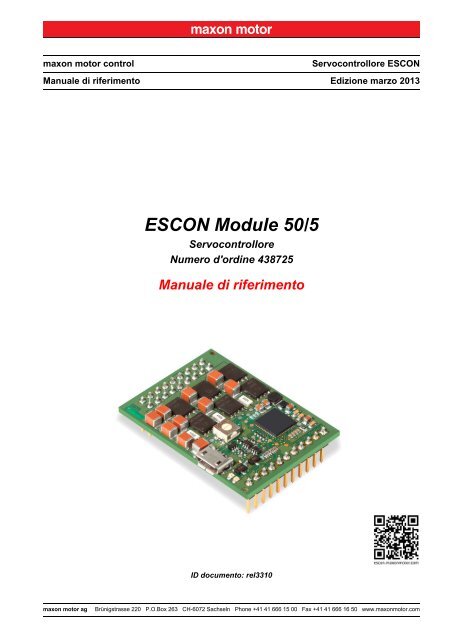
<strong>ESCON</strong> <strong>Module</strong> <strong>50</strong>/5<br />
Servocontrollore<br />
Numero d'or<strong>di</strong>ne 438725<br />
<strong>Manuale</strong> <strong>di</strong> <strong>riferimento</strong><br />
ID documento: rel3310<br />
maxon motor <strong>ag</strong><br />
Brünigstrasse 220 P.O.Box 263 CH-6072 Sachseln Phone +41 41 666 15 00 Fax +41 41 666 16 <strong>50</strong> www.maxonmotor.com
INDICE<br />
1 Informazioni generali 3<br />
1.1 A proposito <strong>di</strong> questo documento. . . . . . . . . . . . . . . . . . . . . . . . . . . . . . . . . . . 3<br />
1.2 Informazioni sul <strong>di</strong>spositivo . . . . . . . . . . . . . . . . . . . . . . . . . . . . . . . . . . . . . . . 5<br />
1.3 Misure <strong>di</strong> sicurezza. . . . . . . . . . . . . . . . . . . . . . . . . . . . . . . . . . . . . . . . . . . . . . 5<br />
2 Specifiche 7<br />
2.1 Dati tecnici . . . . . . . . . . . . . . . . . . . . . . . . . . . . . . . . . . . . . . . . . . . . . . . . . . . . 7<br />
2.2 Norme. . . . . . . . . . . . . . . . . . . . . . . . . . . . . . . . . . . . . . . . . . . . . . . . . . . . . . . . 9<br />
3 Impostazioni 11<br />
3.1 Regole <strong>di</strong> vali<strong>di</strong>tà generale . . . . . . . . . . . . . . . . . . . . . . . . . . . . . . . . . . . . . . . 11<br />
3.2 Determinazione dell'alimentazione elettrica . . . . . . . . . . . . . . . . . . . . . . . . . . 12<br />
3.3 Connessioni . . . . . . . . . . . . . . . . . . . . . . . . . . . . . . . . . . . . . . . . . . . . . . . . . . 13<br />
3.4 Potenziometri . . . . . . . . . . . . . . . . . . . . . . . . . . . . . . . . . . . . . . . . . . . . . . . . . 22<br />
3.5 In<strong>di</strong>catori <strong>di</strong> stato . . . . . . . . . . . . . . . . . . . . . . . . . . . . . . . . . . . . . . . . . . . . . . 23<br />
4 Cabl<strong>ag</strong>gio 25<br />
4.1 <strong>Motor</strong>i DC . . . . . . . . . . . . . . . . . . . . . . . . . . . . . . . . . . . . . . . . . . . . . . . . . . . . 26<br />
4.2 <strong>Motor</strong>i EC . . . . . . . . . . . . . . . . . . . . . . . . . . . . . . . . . . . . . . . . . . . . . . . . . . . . 29<br />
5 Guida alla progettazione della scheda madre 31<br />
5.1 Requisiti dei componenti <strong>di</strong> fornitori terzi . . . . . . . . . . . . . . . . . . . . . . . . . . . . 32<br />
5.2 Linee guida per la progettazione . . . . . . . . . . . . . . . . . . . . . . . . . . . . . . . . . . 35<br />
5.3 Footprint THT . . . . . . . . . . . . . . . . . . . . . . . . . . . . . . . . . . . . . . . . . . . . . . . . . 35<br />
5.4 Assegnazione delle connessioni . . . . . . . . . . . . . . . . . . . . . . . . . . . . . . . . . . 36<br />
5.5 Dati tecnici . . . . . . . . . . . . . . . . . . . . . . . . . . . . . . . . . . . . . . . . . . . . . . . . . . . 36<br />
5.6 Disegno quotato . . . . . . . . . . . . . . . . . . . . . . . . . . . . . . . . . . . . . . . . . . . . . . . 36<br />
5.7 <strong>ESCON</strong> <strong>Module</strong> Motherboard (438779) . . . . . . . . . . . . . . . . . . . . . . . . . . . . . 37<br />
5.8 Pezzi <strong>di</strong> ricambio . . . . . . . . . . . . . . . . . . . . . . . . . . . . . . . . . . . . . . . . . . . . . . <strong>50</strong><br />
LEGGERE INNANZI TUTTO QUANTO SEGUE<br />
Le presenti istruzioni sono destinate a tecnici qualificati. Per poter effettuare qualunque operazione è necessario:<br />
• aver letto e compreso il presente manuale e<br />
• attenersi alle istruzioni in esso contenute.<br />
L'<strong>ESCON</strong> <strong>Module</strong> <strong>50</strong>/5 è da considerarsi come “quasi-macchina” ai sensi della <strong>di</strong>rettiva UE 2006/42/CE, articolo 2,<br />
par<strong>ag</strong>rafo (g) ed è concepito per essere integrato in altre macchine, quasi-macchine o attrezzature o combinato<br />
con esse.<br />
Non è pertanto consentito mettere in servizio il <strong>di</strong>spositivo ...<br />
• prima <strong>di</strong> essersi assicurati che la macchina/il sistema in cui deve essere integrato sia conforme ai requisiti stabiliti<br />
dalla <strong>di</strong>rettiva UE;<br />
• finché la macchina in cui viene integrato non sod<strong>di</strong>sfa tutti i criteri rilevanti in materia <strong>di</strong> salute e sicurezza;<br />
• finché non sono state stabilite tutte le interfacce necessarie, nel rispetto dei requisiti specificati.<br />
maxon motor control<br />
A-2 ID documento: rel3310 Servocontrollore <strong>ESCON</strong><br />
E<strong>di</strong>zione: marzo 2013 <strong>Manuale</strong> <strong>di</strong> <strong>riferimento</strong> <strong>ESCON</strong> <strong>Module</strong> <strong>50</strong>/5<br />
© 2013 maxon motor. Con riserva <strong>di</strong> mo<strong>di</strong>fiche senza necessità <strong>di</strong> preavviso.
Informazioni generali<br />
A proposito <strong>di</strong> questo documento<br />
1 Informazioni generali<br />
1.1 A proposito <strong>di</strong> questo documento<br />
1.1.1 Uso previsto<br />
Il presente documento ha lo scopo <strong>di</strong> familiarizzare l'utente con il servocontrollore <strong>ESCON</strong> <strong>Module</strong> <strong>50</strong>/5.<br />
Descrive le operazioni necessarie per un'installazione e/o una messa in servizio sicure e adeguate allo<br />
scopo. L'osservanza delle istruzioni<br />
• consente <strong>di</strong> evitare situazioni pericolose,<br />
• riduce al minimo i tempi <strong>di</strong> installazione e/o messa in servizio,<br />
• riduce il rischio <strong>di</strong> guasti e aumenta la durata <strong>di</strong> vita dell'attrezzatura descritta.<br />
Nel documento sono contenuti dati relativi alle prestazioni, specifiche, informazioni sulle norme<br />
da osservare, dett<strong>ag</strong>li su collegamenti e assegnazione delle connessioni ed esempi <strong>di</strong> cabl<strong>ag</strong>gio.<br />
All'interno del presente documento è presente la guida alla progettazione della scheda madre<br />
e in<strong>di</strong>cazioni dett<strong>ag</strong>liate relative all'«<strong>ESCON</strong> <strong>Module</strong> Motherboard» <strong>di</strong>sponibile come opzione.<br />
1.1.2 Gruppo target<br />
Il presente documento è destinato a personale specializzato istruito ed esperto. Fornisce informazioni<br />
che consentono <strong>di</strong> comprendere e realizzare correttamente le operazioni necessarie.<br />
1.1.3 Modo d'impiego<br />
Prestare attenzione alle seguenti notazioni e co<strong>di</strong>fiche, che verranno utilizzate nel corso del documento.<br />
Notazione<br />
(n)<br />
<br />
Significato<br />
si riferisce a un componente (ad es. numero d'or<strong>di</strong>ne, posizione in un elenco ecc.)<br />
sta per “vedere”, “vedere anche”, “prestare attenzione a” o “andare al punto”<br />
Tabella 1-1 Notazione utilizzata<br />
1.1.4 Simboli & segnali<br />
Nel corso del presente documento vengono utilizzati i seguenti simboli e segnali.<br />
Tipo Simbolo Significato<br />
PERICOLO<br />
In<strong>di</strong>ca una situazione <strong>di</strong> pericolo imminente.<br />
L'inosservanza ha come conseguenza lesioni<br />
molto gravi e anche mortali.<br />
Avvertenza<br />
<strong>di</strong> sicurezza<br />
(tipico)<br />
AVVERTIMENTO<br />
ATTENZIONE<br />
In<strong>di</strong>ca una potenziale situazione <strong>di</strong> pericolo.<br />
L'inosservanza può avere come conseguenza<br />
lesioni molto gravi e anche mortali.<br />
In<strong>di</strong>ca una possibile situazione <strong>di</strong> pericolo<br />
o richiama l'attenzione su pratiche scorrette dal<br />
punto <strong>di</strong> vista della sicurezza. L'inosservanza<br />
può avere come conseguenza lesioni.<br />
Operazione<br />
non<br />
consentita<br />
(tipico)<br />
In<strong>di</strong>ca un'operazione che comporta dei pericoli e dunque non è<br />
consentita!<br />
maxon motor control<br />
Servocontrollore <strong>ESCON</strong> ID documento: rel3310 1-3<br />
<strong>Manuale</strong> <strong>di</strong> <strong>riferimento</strong> <strong>ESCON</strong> <strong>Module</strong> <strong>50</strong>/5 E<strong>di</strong>zione: marzo 2013<br />
© 2013 maxon motor. Con riserva <strong>di</strong> mo<strong>di</strong>fiche senza necessità <strong>di</strong> preavviso.
Informazioni generali<br />
A proposito <strong>di</strong> questo documento<br />
Tipo Simbolo Significato<br />
Operazione<br />
obbligatoria<br />
(tipico)<br />
In<strong>di</strong>ca un'operazione che risulta necessaria e dunque deve essere<br />
assolutamente eseguita!<br />
Richiesta/Nota/<br />
Osservazione<br />
In<strong>di</strong>ca un'operazione che deve essere eseguita<br />
per poter procedere, oppure fornisce<br />
informazioni più dett<strong>ag</strong>liate da tenere in<br />
considerazione su un determinato aspetto.<br />
Informazione<br />
Metodo consigliato<br />
In<strong>di</strong>ca una raccomandazione o una proposta<br />
sul modo <strong>di</strong> procedere più appropriato.<br />
Danneggiamento<br />
Fornisce suggerimenti utili per evitare possibili<br />
danni all'attrezzatura.<br />
Tabella 1-2 Simboli e segnali<br />
1.1.5 Marchi depositati e nomi commerciali<br />
Per favorire la leggibilità, i nomi commerciali registrati con il relativo simbolo <strong>di</strong> marchio depositato compaiono<br />
un'unica volta nell'elenco seguente. Rimane sottinteso che i nomi commerciali (l'elenco non è<br />
necessariamente esaustivo) sono protetti dalle leggi sul copyright e/o costituiscono proprietà intellettuale,<br />
anche se il simbolo corrispondente viene omesso nel prosieguo del documento.<br />
Nome commerciale<br />
Windows®<br />
Proprietario del marchio<br />
© Microsoft Corporation, USA-Redmond, WA<br />
Tabella 1-3 Marchi depositati e nomi commerciali<br />
1.1.6 Copyright<br />
© 2013 maxon motor. Tutti i <strong>di</strong>ritti riservati.<br />
Il presente documento, o anche solo estratti <strong>di</strong> esso, sono protetti da <strong>di</strong>ritti d'autore. In assenza <strong>di</strong><br />
un'espressa autorizzazione scritta da parte <strong>di</strong> maxon motor <strong>ag</strong>, ogni suo impiego (incluse riproduzione,<br />
traduzione, micromazione o altre forme <strong>di</strong> elaborazione elettronica dei dati) al <strong>di</strong> fuori degli stretti limiti<br />
stabiliti dalle leggi sui <strong>di</strong>ritti d'autore è vietato e perseguibile penalmente.<br />
maxon motor <strong>ag</strong><br />
Brünigstrasse 220<br />
Postfach 263<br />
CH-6072 Sachseln<br />
Telefono<br />
Fax<br />
Web<br />
+41 41 666 15 00<br />
+41 41 666 16 <strong>50</strong><br />
www.maxonmotor.com<br />
maxon motor control<br />
1-4 ID documento: rel3310 Servocontrollore <strong>ESCON</strong><br />
E<strong>di</strong>zione: marzo 2013 <strong>Manuale</strong> <strong>di</strong> <strong>riferimento</strong> <strong>ESCON</strong> <strong>Module</strong> <strong>50</strong>/5<br />
© 2013 maxon motor. Con riserva <strong>di</strong> mo<strong>di</strong>fiche senza necessità <strong>di</strong> preavviso.
1.2 Informazioni sul <strong>di</strong>spositivo<br />
Informazioni generali<br />
Informazioni sul <strong>di</strong>spositivo<br />
L'<strong>ESCON</strong> <strong>Module</strong> <strong>50</strong>/5 è un potente e compatto servocontrollore con sistema PWM (modulazione<br />
<strong>di</strong> larghezza <strong>di</strong> impulso) a 4 quadranti per il comando efficiente <strong>di</strong> motori DC con spazzole con m<strong>ag</strong>neti<br />
permanenti o motori EC senza spazzole fino a ca. 2<strong>50</strong> watt.<br />
Le <strong>di</strong>verse modalità operative <strong>di</strong>sponibili (regolatore <strong>di</strong> velocità, selettore <strong>di</strong> velocità e regolatore <strong>di</strong> corrente)<br />
lo rendono adatto anche ad applicazioni dai requisiti particolarmente elevati. L'<strong>ESCON</strong> <strong>Module</strong><br />
<strong>50</strong>/5 è concepito per essere comandato me<strong>di</strong>ante un valore nominale analogico. Dispone <strong>di</strong> numerose<br />
funzionalità con ingressi e uscite <strong>di</strong>gitali e analogici.<br />
Il modulo plug-in OEM miniaturizzato può essere integrato <strong>di</strong>rettamente nelle applicazioni complesse<br />
del cliente. Per la prima messa in servizio è <strong>di</strong>sponibile l'apposita scheda madre.<br />
Attraverso la porta USB, il <strong>di</strong>spositivo viene configurato tramite l'interfaccia grafica utente<br />
«<strong>ESCON</strong> Stu<strong>di</strong>o» per PC Windows.<br />
La versione più recente del software <strong>ESCON</strong> (così come l'e<strong>di</strong>zione più recente della documentazione)<br />
è scaricabile dal sito internet http://escon.maxonmotor.com.<br />
1.3 Misure <strong>di</strong> sicurezza<br />
• Assicurarsi <strong>di</strong> aver letto la nota “LEGGERE INNANZI TUTTO QUANTO SEGUE” a p<strong>ag</strong>ina A-2.<br />
• Non intraprendere alcun lavoro se non si è in possesso delle conoscenze e competenze necessarie<br />
(Capitolo “1.1.2 Gruppo target” a p<strong>ag</strong>ina 1-3).<br />
• Consultare il Capitolo “1.1.4 Simboli & segnali” a p<strong>ag</strong>ina 1-3 per essere certi <strong>di</strong> comprendere<br />
i simboli utilizzati nel corso del documento.<br />
• Attenersi a tutte le norme vigenti nel paese e luogo <strong>di</strong> impiego in materia <strong>di</strong> prevenzione degli<br />
infortuni, sicurezza sul lavoro e protezione ambientale.<br />
PERICOLO<br />
Alta tensione e/o scossa elettrica<br />
Il contatto con conduttori <strong>di</strong> tensione può causare lesioni gravi e anche mortali!<br />
• Fino a prova contraria, considerare tutti i cavi <strong>di</strong> rete come potenzialmente sotto tensione.<br />
• Assicurarsi che nessuna delle due estremità dei cavi sia collegata alla rete <strong>di</strong> alimentazione.<br />
• Accertarsi che l'alimentazione <strong>di</strong> tensione non possa essere inserita per tutta la durata dei lavori<br />
previsti.<br />
• Attenersi alle procedure prescritte per blocc<strong>ag</strong>gio e messa fuori servizio.<br />
• Accertarsi che tutti gli interruttori <strong>di</strong> accensione siano bloccati contro un azionamento involontario<br />
e contrassegnati con il nome del responsabile.<br />
Requisiti<br />
• Assicurarsi che tutti i componenti <strong>ag</strong>gregati siano installati in modo conforme alle norme vigenti nel<br />
luogo <strong>di</strong> impiego.<br />
• Tenere presente che un <strong>di</strong>spositivo elettronico non può, in linea <strong>di</strong> principio, essere considerato a<br />
prova <strong>di</strong> guasto. Assicurarsi pertanto che la macchina/l'attrezzatura sia provvista <strong>di</strong> un <strong>di</strong>spositivo<br />
<strong>di</strong> monitor<strong>ag</strong>gio e <strong>di</strong> sicurezza in<strong>di</strong>pendente. In caso <strong>di</strong> malfunzionamento o impiego scorretto della<br />
macchina/dell'attrezzatura, <strong>di</strong> guasto dell'unità <strong>di</strong> comando o <strong>di</strong> rottura/<strong>di</strong>stacco <strong>di</strong> un cavo ecc.,<br />
l'intero sistema <strong>di</strong> motorizzazione deve passare a una modalità operativa <strong>di</strong> sicurezza e permanere<br />
in tale modalità.<br />
• Attenzione: l'utente non è autorizzato a eseguire alcun tipo <strong>di</strong> riparazione sui componenti forniti da<br />
maxon motor.<br />
Componente sensibile alle scariche elettrostatiche (ESD)<br />
• Indossare adeguati indumenti antielettrostatici.<br />
• Maneggiare il <strong>di</strong>spositivo con la massima precauzione.<br />
maxon motor control<br />
Servocontrollore <strong>ESCON</strong> ID documento: rel3310 1-5<br />
<strong>Manuale</strong> <strong>di</strong> <strong>riferimento</strong> <strong>ESCON</strong> <strong>Module</strong> <strong>50</strong>/5 E<strong>di</strong>zione: marzo 2013<br />
© 2013 maxon motor. Con riserva <strong>di</strong> mo<strong>di</strong>fiche senza necessità <strong>di</strong> preavviso.
Informazioni generali<br />
Misure <strong>di</strong> sicurezza<br />
••P<strong>ag</strong>ina lasciata vuota intenzionalmente••<br />
maxon motor control<br />
1-6 ID documento: rel3310 Servocontrollore <strong>ESCON</strong><br />
E<strong>di</strong>zione: marzo 2013 <strong>Manuale</strong> <strong>di</strong> <strong>riferimento</strong> <strong>ESCON</strong> <strong>Module</strong> <strong>50</strong>/5<br />
© 2013 maxon motor. Con riserva <strong>di</strong> mo<strong>di</strong>fiche senza necessità <strong>di</strong> preavviso.
Specifiche<br />
Dati tecnici<br />
2 Specifiche<br />
2.1 Dati tecnici<br />
<strong>ESCON</strong> <strong>Module</strong> <strong>50</strong>/5 (438725)<br />
Tensione nominale <strong>di</strong> esercizio +V CC<br />
10…<strong>50</strong> VDC<br />
Tensione <strong>di</strong> esercizio assoluta<br />
+V CC min<br />
/+V CC max<br />
8 VDC/56 VDC<br />
Configurazione<br />
elettrica<br />
Tensione <strong>di</strong> uscita (max.)<br />
Corrente <strong>di</strong> uscita I cont<br />
/I max<br />
(
Specifiche<br />
Dati tecnici<br />
<strong>ESCON</strong> <strong>Module</strong> <strong>50</strong>/5 (438725)<br />
Misure<br />
Con<strong>di</strong>zioni<br />
ambientali<br />
Peso<br />
Dimensioni (L x P x A)<br />
Fiss<strong>ag</strong>gio<br />
Temperatura<br />
Umi<strong>di</strong>tà dell'aria<br />
ca. 12 g<br />
43,2 x 31,8 x 12,7 mm<br />
A innesto in morsettiere femmina passo 2,54 mm<br />
Esercizio –30…+45 °C<br />
Range esteso *1) +45…+75 °C<br />
Derating: –0.167 A/°C<br />
M<strong>ag</strong>azzin<strong>ag</strong>gio –40…+85 °C<br />
20…80% (senza condensa)<br />
Nota: *1) Il funzionamento all'interno del range <strong>di</strong> temperatura esteso è ammesso, comporta però un derating<br />
(riduzione della corrente <strong>di</strong> uscita max.) delle proporzioni in<strong>di</strong>cate.<br />
Tabella 2-4 Dati tecnici<br />
Figura 2-1 Disegno quotato [mm]<br />
maxon motor control<br />
2-8 ID documento: rel3310 Servocontrollore <strong>ESCON</strong><br />
E<strong>di</strong>zione: marzo 2013 <strong>Manuale</strong> <strong>di</strong> <strong>riferimento</strong> <strong>ESCON</strong> <strong>Module</strong> <strong>50</strong>/5<br />
© 2013 maxon motor. Con riserva <strong>di</strong> mo<strong>di</strong>fiche senza necessità <strong>di</strong> preavviso.
Specifiche<br />
Norme<br />
2.2 Norme<br />
Il <strong>di</strong>spositivo descritto è stato sottoposto a collaudo ed è risultato conforme alle norme sotto elencate.<br />
Nella pratica, tuttavia, solo un test CEM effettuato sulla totalità del sistema (l'intera attrezzatura pronta<br />
all'uso, comprendente tutti i singoli componenti quali ad es. motore, servocontrollore, alimentatore, filtro<br />
CEM, cavi ecc.) può garantire un funzionamento sicuro e privo <strong>di</strong> errori.<br />
Nota importante<br />
La conformità del <strong>di</strong>spositivo descritto alle norme citate non implica necessariamente che esso risulti<br />
conforme una volta inserito nel sistema complessivo pronto per l'uso. Per verificare la conformità<br />
dell'intero sistema è necessario sottoporlo nella sua totalità, con tutti i suoi componenti, ai test CEM<br />
richiesti.<br />
Compatibilità elettrom<strong>ag</strong>netica<br />
Norme generiche<br />
Norme applicate<br />
IEC/EN 61000-6-2<br />
IEC/EN 61000-6-3<br />
IEC/EN 61000-6-3<br />
IEC/EN 5<strong>50</strong>22<br />
(CISPR22)<br />
IEC/EN 61000-4-3<br />
IEC/EN 61000-4-4<br />
IEC/EN 61000-4-6<br />
Immunità per gli ambienti industriali<br />
Emissione <strong>di</strong> <strong>di</strong>sturbi per gli ambienti residenziali,<br />
commerciali e le piccole imprese<br />
Emissione <strong>di</strong> <strong>di</strong>sturbi da apparecchiature per la tecnologia<br />
dell'informazione<br />
Immunità ai campi elettrom<strong>ag</strong>netici irra<strong>di</strong>ati a<br />
ra<strong>di</strong>ofrequenza >10 V/m<br />
Immunità ai transitori elettrici veloci (burst) ±2 kV<br />
Immunità ai <strong>di</strong>sturbi condotti, indotti da campi a<br />
ra<strong>di</strong>ofrequenza 10 Vrms<br />
Norme ambientali<br />
IEC/EN 60068-2-6<br />
MIL-STD-810F<br />
Altre norme<br />
Influssi ambientali – Prova Fc: vibrazioni (sinusoidali)<br />
Random transport<br />
Norme <strong>di</strong> sicurezza<br />
UL File Number E243951; scheda <strong>di</strong> circuito stampato non guarnita<br />
Tabella 2-5 Norme<br />
maxon motor control<br />
Servocontrollore <strong>ESCON</strong> ID documento: rel3310 2-9<br />
<strong>Manuale</strong> <strong>di</strong> <strong>riferimento</strong> <strong>ESCON</strong> <strong>Module</strong> <strong>50</strong>/5 E<strong>di</strong>zione: marzo 2013<br />
© 2013 maxon motor. Con riserva <strong>di</strong> mo<strong>di</strong>fiche senza necessità <strong>di</strong> preavviso.
Specifiche<br />
Norme<br />
••P<strong>ag</strong>ina lasciata vuota intenzionalmente••<br />
maxon motor control<br />
2-10 ID documento: rel3310 Servocontrollore <strong>ESCON</strong><br />
E<strong>di</strong>zione: marzo 2013 <strong>Manuale</strong> <strong>di</strong> <strong>riferimento</strong> <strong>ESCON</strong> <strong>Module</strong> <strong>50</strong>/5<br />
© 2013 maxon motor. Con riserva <strong>di</strong> mo<strong>di</strong>fiche senza necessità <strong>di</strong> preavviso.
Impostazioni<br />
Regole <strong>di</strong> vali<strong>di</strong>tà generale<br />
3 Impostazioni<br />
NOTA IMPORTANTE: PRESUPPOSTI NECESSARI PER L'AUTORIZZAZIONE A PROCEDERE ALL'INSTALLAZIONE<br />
L'<strong>ESCON</strong> <strong>Module</strong> <strong>50</strong>/5 è da considerarsi come “quasi-macchina” ai sensi della <strong>di</strong>rettiva UE 2006/42/CE,<br />
articolo 2, par<strong>ag</strong>rafo (g) ed è concepito per essere integrato in altre macchine, quasi-macchine<br />
o attrezzature o combinato con esse.<br />
AVVERTIMENTO<br />
Pericolo <strong>di</strong> lesioni<br />
Un uso del <strong>di</strong>spositivo all'interno <strong>di</strong> un sistema non completamente conforme ai requisiti della<br />
<strong>di</strong>rettiva UE 2006/42/CE può avere come conseguenza gravi lesioni!<br />
• Non mettere in servizio il <strong>di</strong>spositivo senza prima essersi assicurati che la macchina in cui viene<br />
integrato sod<strong>di</strong>sfi i requisiti richiesti dalla <strong>di</strong>rettiva UE.<br />
• Non mettere in servizio il <strong>di</strong>spositivo finché la macchina in cui viene integrato non sod<strong>di</strong>sfa tutti<br />
i criteri rilevanti in materia <strong>di</strong> prevenzione degli infortuni e sicurezza sul lavoro.<br />
• Non mettere in servizio il <strong>di</strong>spositivo finché non sono state stabilite tutte le interfacce necessarie<br />
e non sono sod<strong>di</strong>sfatti tutti i requisiti richiesti nel presente documento.<br />
3.1 Regole <strong>di</strong> vali<strong>di</strong>tà generale<br />
Tensione <strong>di</strong> esercizio massima consentita<br />
• Assicurarsi che la tensione <strong>di</strong> esercizio sia compresa tra 10 e <strong>50</strong> VDC.<br />
• Una tensione <strong>di</strong> esercizio superiore a 56 VDC o una polarità errata <strong>di</strong>struggono il <strong>di</strong>spositivo.<br />
• Tenere presente che la corrente richiesta <strong>di</strong>pende dal momento <strong>di</strong> carico. I limiti <strong>di</strong> corrente<br />
dell'<strong>ESCON</strong> <strong>Module</strong> <strong>50</strong>/5 sono i seguenti: in servizio continuo max. 5 A/per breve tempo<br />
(accelerazione) max. 15 A.<br />
maxon motor control<br />
Servocontrollore <strong>ESCON</strong> ID documento: rel3310 3-11<br />
<strong>Manuale</strong> <strong>di</strong> <strong>riferimento</strong> <strong>ESCON</strong> <strong>Module</strong> <strong>50</strong>/5 E<strong>di</strong>zione: marzo 2013<br />
© 2013 maxon motor. Con riserva <strong>di</strong> mo<strong>di</strong>fiche senza necessità <strong>di</strong> preavviso.
Impostazioni<br />
Determinazione dell'alimentazione elettrica<br />
3.2 Determinazione dell'alimentazione elettrica<br />
In linea <strong>di</strong> massima è possibile impiegare qualunque alimentazione sod<strong>di</strong>sfi le esigenze minime sotto<br />
in<strong>di</strong>cate.<br />
Requisiti per l'alimentazione elettrica<br />
Tensione <strong>di</strong> uscita<br />
Tensione <strong>di</strong> uscita<br />
assoluta<br />
Corrente <strong>di</strong> uscita<br />
+V CC<br />
10…<strong>50</strong> VDC<br />
Min. 8 VDC; max. 56 VDC<br />
in funzione del carico<br />
(in servizio continuo max. 5 A; per breve tempo (accelerazione)<br />
max. 15 A (
3.3 Connessioni<br />
Impostazioni<br />
Connessioni<br />
Le connessioni effettive <strong>di</strong>pendono dalla configurazione complessiva del singolo sistema <strong>di</strong> motorizzazione<br />
e dal tipo <strong>di</strong> motore impiegato.<br />
Attenersi a quanto descritto rispettando la sequenza in<strong>di</strong>cata e utilizzare lo schema <strong>di</strong> connessione<br />
più adatto ai componenti utilizzati. Gli schemi corrispondenti si trovano al Capitolo “4 Cabl<strong>ag</strong>gio” a<br />
p<strong>ag</strong>ina 4-25.<br />
3.3.1 Pie<strong>di</strong>natura<br />
Figura 3-2 Pie<strong>di</strong>natura<br />
Pin Segnale Descrizione<br />
1/2<br />
3/4<br />
5/6<br />
<strong>Motor</strong>e (+M)<br />
Avvolgimento<br />
motore 1<br />
<strong>Motor</strong>e (–M)<br />
Avvolgimento<br />
motore 2<br />
Avvolgimento<br />
motore 3<br />
<strong>Motor</strong>e DC: motore +<br />
<strong>Motor</strong>e EC: avvolgimento 1<br />
<strong>Motor</strong>e DC: motore –<br />
<strong>Motor</strong>e EC: avvolgimento 2<br />
<strong>Motor</strong>e EC: avvolgimento 3<br />
7/8 +V CC Tensione nominale <strong>di</strong> esercizio (+10…+<strong>50</strong> VDC)<br />
9/10<br />
Power_GND<br />
GND<br />
Messa a terra tensione <strong>di</strong> esercizio<br />
Messa a terra<br />
11 +5 VDC<br />
Tensione <strong>di</strong> alimentazione sensore Hall (+5 VDC; ≤30 mA)<br />
Tensione <strong>di</strong> alimentazione encoder (+5 VDC; ≤70 mA)<br />
Tensione <strong>di</strong> uscita ausiliaria (+5 VDC; ≤10 mA)<br />
12 Canale A Canale A encoder<br />
13 Sensore Hall 1 Sensore Hall 1, ingresso<br />
14 Canale A\ Segnale complementare canale A encoder<br />
15 Sensore Hall 2 Sensore Hall 2, ingresso<br />
16 Canale B Canale B encoder<br />
17 Sensore Hall 3 Sensore Hall 3, ingresso<br />
18 Canale B\ Segnale complementare canale B encoder<br />
Tabella 3-6 Pie<strong>di</strong>natura e cabl<strong>ag</strong>gio (pin 1-18)<br />
maxon motor control<br />
Servocontrollore <strong>ESCON</strong> ID documento: rel3310 3-13<br />
<strong>Manuale</strong> <strong>di</strong> <strong>riferimento</strong> <strong>ESCON</strong> <strong>Module</strong> <strong>50</strong>/5 E<strong>di</strong>zione: marzo 2013<br />
© 2013 maxon motor. Con riserva <strong>di</strong> mo<strong>di</strong>fiche senza necessità <strong>di</strong> preavviso.
Impostazioni<br />
Connessioni<br />
Figura 3-3 Pie<strong>di</strong>natura<br />
Pin Segnale Descrizione<br />
19 DigIN/DigOUT4 Ingresso/uscita <strong>di</strong>gitale 4<br />
20 DigIN/DigOUT3 Ingresso/uscita <strong>di</strong>gitale 3<br />
21 DigIN2 Ingresso <strong>di</strong>gitale 2<br />
22 DigIN1 Ingresso <strong>di</strong>gitale 1<br />
23 GND Messa a terra<br />
24 AnOUT2 Uscita analogica 2<br />
25 AnOUT1 Uscita analogica 1<br />
26 AnIN2– Ingresso analogico 2, segnale negativo<br />
27 AnIN2+ Ingresso analogico 2, segnale positivo<br />
28 AnIN1– Ingresso analogico 1, segnale negativo<br />
29 AnIN1+ Ingresso analogico 1, segnale positivo<br />
Tabella 3-7 Pie<strong>di</strong>natura e cabl<strong>ag</strong>gio (pin 19-29)<br />
maxon motor control<br />
3-14 ID documento: rel3310 Servocontrollore <strong>ESCON</strong><br />
E<strong>di</strong>zione: marzo 2013 <strong>Manuale</strong> <strong>di</strong> <strong>riferimento</strong> <strong>ESCON</strong> <strong>Module</strong> <strong>50</strong>/5<br />
© 2013 maxon motor. Con riserva <strong>di</strong> mo<strong>di</strong>fiche senza necessità <strong>di</strong> preavviso.
Impostazioni<br />
Connessioni<br />
3.3.2 Sensore Hall<br />
Tensione <strong>di</strong> alimentazione sensori Hall<br />
+5 VDC<br />
Corrente <strong>di</strong> alimentazione max. per sensori Hall 30 mA<br />
Tensione <strong>di</strong> ingresso<br />
0…24 VDC<br />
Tensione <strong>di</strong> ingresso max.<br />
+24 VDC<br />
Logica 0<br />
Tipico 2,4 V<br />
Resistenza pullup interna 10 kΩ (rispetto a +5,45 V)<br />
Figura 3-4 Circuito <strong>di</strong> ingresso sensore Hall 1 (applicabile anche per sensori Hall 2 e 3)<br />
maxon motor control<br />
Servocontrollore <strong>ESCON</strong> ID documento: rel3310 3-15<br />
<strong>Manuale</strong> <strong>di</strong> <strong>riferimento</strong> <strong>ESCON</strong> <strong>Module</strong> <strong>50</strong>/5 E<strong>di</strong>zione: marzo 2013<br />
© 2013 maxon motor. Con riserva <strong>di</strong> mo<strong>di</strong>fiche senza necessità <strong>di</strong> preavviso.
Impostazioni<br />
Connessioni<br />
3.3.3 Encoder<br />
Metodo consigliato<br />
• I segnali <strong>di</strong>fferenziali sono adeguatamente schermati contro i campi elettrici perturbatori. Per questo<br />
motivo consigliamo la connessione me<strong>di</strong>ante segnale <strong>di</strong> ingresso <strong>di</strong>fferenziale. Il controller supporta<br />
comunque entrambe le opzioni: <strong>di</strong>fferenziale e single-ended (asimmetrico).<br />
• Il controller non richiede alcun impulso in<strong>di</strong>ce (Ch I, Ch I\).<br />
• Per ottenere prestazioni ottimali raccoman<strong>di</strong>amo vivamente l'uso <strong>di</strong> un encoder con driver <strong>di</strong><br />
linea (Line Driver), in assenza del quale fronti <strong>di</strong> commutazione piatti possono causare limitazioni<br />
della velocità.<br />
Tensione <strong>di</strong> ingresso <strong>di</strong>fferenziale min.<br />
Tensione <strong>di</strong> ingresso max.<br />
Ricevitore <strong>di</strong> linea (Line Receiver, interno)<br />
Frequenza <strong>di</strong> ingresso max.<br />
Differenziale<br />
±200 mV<br />
+12 VDC/–12 VDC<br />
EIA RS422 Standard<br />
1 MHz<br />
Figura 3-5 Circuito <strong>di</strong> ingresso encoder Ch A “<strong>di</strong>fferenziale” (applicabile anche per Ch B)<br />
maxon motor control<br />
3-16 ID documento: rel3310 Servocontrollore <strong>ESCON</strong><br />
E<strong>di</strong>zione: marzo 2013 <strong>Manuale</strong> <strong>di</strong> <strong>riferimento</strong> <strong>ESCON</strong> <strong>Module</strong> <strong>50</strong>/5<br />
© 2013 maxon motor. Con riserva <strong>di</strong> mo<strong>di</strong>fiche senza necessità <strong>di</strong> preavviso.
Impostazioni<br />
Connessioni<br />
Tensione <strong>di</strong> ingresso<br />
Tensione <strong>di</strong> ingresso max.<br />
Logica 0<br />
Logica 1<br />
Corrente <strong>di</strong> ingresso elevata<br />
Corrente <strong>di</strong> ingresso ridotta<br />
Frequenza <strong>di</strong> ingresso max.<br />
Single-ended<br />
0…5 VDC<br />
+12 VDC/–12 VDC<br />
2,4 V<br />
I IH<br />
= tipico –<strong>50</strong> μA a 5 V<br />
I IL<br />
= tipico –5<strong>50</strong> μA a 0 V<br />
100 kHz<br />
Figura 3-6 Circuito <strong>di</strong> ingresso encoder Ch A “single-ended” (applicabile anche per Ch B)<br />
maxon motor control<br />
Servocontrollore <strong>ESCON</strong> ID documento: rel3310 3-17<br />
<strong>Manuale</strong> <strong>di</strong> <strong>riferimento</strong> <strong>ESCON</strong> <strong>Module</strong> <strong>50</strong>/5 E<strong>di</strong>zione: marzo 2013<br />
© 2013 maxon motor. Con riserva <strong>di</strong> mo<strong>di</strong>fiche senza necessità <strong>di</strong> preavviso.
Impostazioni<br />
Connessioni<br />
3.3.4 I/O <strong>di</strong>gitali<br />
3.3.4.1 Ingresso <strong>di</strong>gitale 1<br />
Tensione <strong>di</strong> ingresso<br />
Tensione <strong>di</strong> ingresso max.<br />
Logica 0<br />
Logica 1<br />
Resistenza <strong>di</strong> ingresso<br />
Corrente <strong>di</strong> ingresso con logica 1<br />
Ritardo <strong>di</strong> commutazione<br />
0…36 VDC<br />
+36 VDC/–36 VDC<br />
Tipico 2,4 V<br />
Tipico 47 kΩ (
Impostazioni<br />
Connessioni<br />
3.3.4.3 Ingressi/uscite <strong>di</strong>gitali 3 e 4<br />
Tensione <strong>di</strong> ingresso<br />
Tensione <strong>di</strong> ingresso max.<br />
Logica 0<br />
Logica 1<br />
Resistenza <strong>di</strong> ingresso<br />
Corrente <strong>di</strong> ingresso con logica 1<br />
Ritardo <strong>di</strong> commutazione<br />
DigIN<br />
0…36 VDC<br />
+36 VDC<br />
Tipico 2,4 V<br />
Tipico 47 kΩ (
Impostazioni<br />
Connessioni<br />
3.3.5 I/O analogici<br />
3.3.5.1 Ingressi analogici 1 e 2<br />
Tensione <strong>di</strong> ingresso<br />
Tensione <strong>di</strong> ingresso max.<br />
Tensione <strong>di</strong> modo comune<br />
Resistenza <strong>di</strong> ingresso<br />
Convertitore A/D<br />
Risoluzione<br />
Ampiezza <strong>di</strong> banda<br />
–10…+10 VDC (<strong>di</strong>fferenziale)<br />
+24 VDC/–24 VDC<br />
–5…+10 VDC (riferita a massa)<br />
80 kΩ (<strong>di</strong>fferenziale)<br />
65 kΩ (riferita a massa)<br />
12 bit<br />
5,64 mV<br />
10 kHz<br />
Figura 3-11 Circuito AnIN1 (applicabile anche per AnIN2)<br />
3.3.5.2 Uscite analogiche 1 e 2<br />
Tensione <strong>di</strong> uscita<br />
Convertitore D/A<br />
Risoluzione<br />
Frequenza <strong>di</strong> ripetizione<br />
Ampiezza <strong>di</strong> banda analogica dell'amplificatore<br />
<strong>di</strong> uscita<br />
Carico capacitivo max.<br />
Corrente <strong>di</strong> uscita max.<br />
–4…+4 VDC<br />
12 bit<br />
2,42 mV<br />
AnOUT1: 26,8 kHz<br />
AnOUT2: 5,4 kHz<br />
<strong>50</strong> kHz<br />
300 nF<br />
Nota: La velocità dell'aumento è limitatamente<br />
proporzionale al carico capacitivo (ad esempio<br />
5 V/ms a 300 nF).<br />
1 mA<br />
Figura 3-12 Circuito AnOUT1 (applicabile anche per AnOUT2)<br />
maxon motor control<br />
3-20 ID documento: rel3310 Servocontrollore <strong>ESCON</strong><br />
E<strong>di</strong>zione: marzo 2013 <strong>Manuale</strong> <strong>di</strong> <strong>riferimento</strong> <strong>ESCON</strong> <strong>Module</strong> <strong>50</strong>/5<br />
© 2013 maxon motor. Con riserva <strong>di</strong> mo<strong>di</strong>fiche senza necessità <strong>di</strong> preavviso.
Impostazioni<br />
Connessioni<br />
3.3.6 USB (J7)<br />
Figura 3-13 Connettore femmina per USB J7<br />
Nota<br />
La colonna “Lato B” (Tabella 3-8) si riferisce alla porta USB del computer dell'utente.<br />
J7 e<br />
lato A<br />
Lato B<br />
Segnale<br />
Descrizione<br />
Pin<br />
Pin<br />
1 1 V BUS Tensione <strong>di</strong> alimentazione BUS USB +5 VDC<br />
2 2 D– Data– USB (intrecciato con Data+)<br />
3 3 D+ Data+ USB (intrecciato con Data–)<br />
4 – ID Non assegnato<br />
5 4 GND Messa a terra USB<br />
Tabella 3-8 Connettore femmina per USB J7 – Assegnazione delle connessioni e cabl<strong>ag</strong>gio<br />
USB 2.0 Type A-micro B Cable (403968)<br />
Sezione del cavo Conforme alle specifiche USB 2.0<br />
Lunghezza<br />
Lato A<br />
Lato B<br />
1,5 m<br />
USB tipo “micro B”, maschio<br />
USB tipo “A”, maschio<br />
Tabella 3-9 USB 2.0 Type A-micro B Cable<br />
USB Standard<br />
Velocità <strong>di</strong> trasmissione max.<br />
Tensione <strong>di</strong> esercizio bus max.<br />
Corrente <strong>di</strong> ingresso tipica<br />
Tensione <strong>di</strong> ingresso dati DC max.<br />
2.0 (Full Speed)<br />
12 Mbit/s<br />
+5,25 VDC<br />
60 mA<br />
–0,5…+3,8 VDC<br />
maxon motor control<br />
Servocontrollore <strong>ESCON</strong> ID documento: rel3310 3-21<br />
<strong>Manuale</strong> <strong>di</strong> <strong>riferimento</strong> <strong>ESCON</strong> <strong>Module</strong> <strong>50</strong>/5 E<strong>di</strong>zione: marzo 2013<br />
© 2013 maxon motor. Con riserva <strong>di</strong> mo<strong>di</strong>fiche senza necessità <strong>di</strong> preavviso.
Impostazioni<br />
Potenziometri<br />
3.4 Potenziometri<br />
POTENZIOMETRO P1<br />
Campo <strong>di</strong> regolazione 210°<br />
Tipo<br />
Lineare<br />
Figura 3-14 Potenziometri – Posizione <strong>di</strong> mont<strong>ag</strong>gio e campo <strong>di</strong> regolazione<br />
maxon motor control<br />
3-22 ID documento: rel3310 Servocontrollore <strong>ESCON</strong><br />
E<strong>di</strong>zione: marzo 2013 <strong>Manuale</strong> <strong>di</strong> <strong>riferimento</strong> <strong>ESCON</strong> <strong>Module</strong> <strong>50</strong>/5<br />
© 2013 maxon motor. Con riserva <strong>di</strong> mo<strong>di</strong>fiche senza necessità <strong>di</strong> preavviso.
3.5 In<strong>di</strong>catori <strong>di</strong> stato<br />
Impostazioni<br />
In<strong>di</strong>catori <strong>di</strong> stato<br />
Dei <strong>di</strong>o<strong>di</strong> luminosi (LED) consentono <strong>di</strong> visualizzare lo stato <strong>di</strong> servizio corrente (luce verde) nonché<br />
possibili errori (luce rossa).<br />
Figura 3-15 LED – Posizione <strong>di</strong> mont<strong>ag</strong>gio<br />
LED<br />
verde rosso<br />
Stato/errore<br />
Spento Spento INIT<br />
Lampeggio<br />
lento<br />
Spento BLOCCO<br />
Acceso Spento ABILITAZIONE<br />
2x Spento INTERRUZIONE; ARRESTO<br />
Spento 1x ERRORE<br />
Spento 2x ERRORE<br />
• Errore +Vcc sovratensione<br />
• Errore +Vcc sottotensione<br />
• Errore +5 VDC sottotensione<br />
• Errore <strong>di</strong> sovraccarico termico<br />
• Errore <strong>di</strong> sovracorrente<br />
• Errore <strong>di</strong> protezione da sovraccarico sta<strong>di</strong>o<br />
<strong>di</strong> potenza<br />
• Errore interno hardware<br />
Spento 3x ERRORE<br />
• Errore encoder – Rottura del cavo<br />
• Errore encoder – Polarità<br />
• Errore <strong>di</strong>namo tachimetrica DC – Rottura del cavo<br />
• Errore <strong>di</strong>namo tachimetrica DC – Polarità<br />
Spento 4x ERRORE • Errore <strong>di</strong> valore nominale PWM fuori range<br />
Spento 5x ERRORE<br />
Spento Acceso ERRORE<br />
• Errore sensori Hall – Logica <strong>di</strong> commutazione<br />
• Errore sensori Hall – Sequenza <strong>di</strong> commutazione<br />
• Errore sensori Hall – Frequenza troppo alta<br />
• Errore Auto Tuning – Identificazione<br />
• Errore interno software<br />
Tabella 3-10 LED – Interpretazione della visualizzazione degli stati<br />
maxon motor control<br />
Servocontrollore <strong>ESCON</strong> ID documento: rel3310 3-23<br />
<strong>Manuale</strong> <strong>di</strong> <strong>riferimento</strong> <strong>ESCON</strong> <strong>Module</strong> <strong>50</strong>/5 E<strong>di</strong>zione: marzo 2013<br />
© 2013 maxon motor. Con riserva <strong>di</strong> mo<strong>di</strong>fiche senza necessità <strong>di</strong> preavviso.
Impostazioni<br />
In<strong>di</strong>catori <strong>di</strong> stato<br />
••P<strong>ag</strong>ina lasciata vuota intenzionalmente••<br />
maxon motor control<br />
3-24 ID documento: rel3310 Servocontrollore <strong>ESCON</strong><br />
E<strong>di</strong>zione: marzo 2013 <strong>Manuale</strong> <strong>di</strong> <strong>riferimento</strong> <strong>ESCON</strong> <strong>Module</strong> <strong>50</strong>/5<br />
© 2013 maxon motor. Con riserva <strong>di</strong> mo<strong>di</strong>fiche senza necessità <strong>di</strong> preavviso.
Cabl<strong>ag</strong>gio<br />
4 Cabl<strong>ag</strong>gio<br />
Figura 4-16 Interfacce – Denominazioni e posizione <strong>di</strong> mont<strong>ag</strong>gio<br />
Nota<br />
Nei <strong>di</strong><strong>ag</strong>rammi presentati a continuazione vengono impiegati i seguenti simboli e denominazioni:<br />
• «Analog I/O» sta per ingressi/uscite analogici<br />
• «DC Tacho» sta per <strong>di</strong>namo tachimetrica DC<br />
• «Digital I/O» sta per ingressi/uscite <strong>di</strong>gitali<br />
• «Power Supply» sta per alimentazione elettrica<br />
• Messa a terra (opzionale)<br />
maxon motor control<br />
Servocontrollore <strong>ESCON</strong> ID documento: rel3310 4-25<br />
<strong>Manuale</strong> <strong>di</strong> <strong>riferimento</strong> <strong>ESCON</strong> <strong>Module</strong> <strong>50</strong>/5 E<strong>di</strong>zione: marzo 2013<br />
© 2013 maxon motor. Con riserva <strong>di</strong> mo<strong>di</strong>fiche senza necessità <strong>di</strong> preavviso.
Cabl<strong>ag</strong>gio<br />
<strong>Motor</strong>i DC<br />
4.1 <strong>Motor</strong>i DC<br />
MAXON DC MOTOR<br />
Figura 4-17 maxon DC motor<br />
maxon motor control<br />
4-26 ID documento: rel3310 Servocontrollore <strong>ESCON</strong><br />
E<strong>di</strong>zione: marzo 2013 <strong>Manuale</strong> <strong>di</strong> <strong>riferimento</strong> <strong>ESCON</strong> <strong>Module</strong> <strong>50</strong>/5<br />
© 2013 maxon motor. Con riserva <strong>di</strong> mo<strong>di</strong>fiche senza necessità <strong>di</strong> preavviso.
Cabl<strong>ag</strong>gio<br />
<strong>Motor</strong>i DC<br />
MAXON DC MOTOR CON DINAMO TACHIMETRICA DC<br />
Figura 4-18 maxon DC motor con <strong>di</strong>namo tachimetrica DC<br />
maxon motor control<br />
Servocontrollore <strong>ESCON</strong> ID documento: rel3310 4-27<br />
<strong>Manuale</strong> <strong>di</strong> <strong>riferimento</strong> <strong>ESCON</strong> <strong>Module</strong> <strong>50</strong>/5 E<strong>di</strong>zione: marzo 2013<br />
© 2013 maxon motor. Con riserva <strong>di</strong> mo<strong>di</strong>fiche senza necessità <strong>di</strong> preavviso.
Cabl<strong>ag</strong>gio<br />
<strong>Motor</strong>i DC<br />
MAXON DC MOTOR CON ENCODER<br />
Figura 4-19 maxon DC motor con encoder<br />
maxon motor control<br />
4-28 ID documento: rel3310 Servocontrollore <strong>ESCON</strong><br />
E<strong>di</strong>zione: marzo 2013 <strong>Manuale</strong> <strong>di</strong> <strong>riferimento</strong> <strong>ESCON</strong> <strong>Module</strong> <strong>50</strong>/5<br />
© 2013 maxon motor. Con riserva <strong>di</strong> mo<strong>di</strong>fiche senza necessità <strong>di</strong> preavviso.
Cabl<strong>ag</strong>gio<br />
<strong>Motor</strong>i EC<br />
4.2 <strong>Motor</strong>i EC<br />
MAXON EC MOTOR CON SENSORI HALL<br />
Figura 4-20 maxon EC motor con sensori Hall<br />
maxon motor control<br />
Servocontrollore <strong>ESCON</strong> ID documento: rel3310 4-29<br />
<strong>Manuale</strong> <strong>di</strong> <strong>riferimento</strong> <strong>ESCON</strong> <strong>Module</strong> <strong>50</strong>/5 E<strong>di</strong>zione: marzo 2013<br />
© 2013 maxon motor. Con riserva <strong>di</strong> mo<strong>di</strong>fiche senza necessità <strong>di</strong> preavviso.
Cabl<strong>ag</strong>gio<br />
<strong>Motor</strong>i EC<br />
MAXON EC MOTOR CON SENSORI HALL ED ENCODER<br />
Figura 4-21 maxon EC motor con sensori Hall ed encoder<br />
maxon motor control<br />
4-30 ID documento: rel3310 Servocontrollore <strong>ESCON</strong><br />
E<strong>di</strong>zione: marzo 2013 <strong>Manuale</strong> <strong>di</strong> <strong>riferimento</strong> <strong>ESCON</strong> <strong>Module</strong> <strong>50</strong>/5<br />
© 2013 maxon motor. Con riserva <strong>di</strong> mo<strong>di</strong>fiche senza necessità <strong>di</strong> preavviso.
Guida alla progettazione della scheda madre<br />
5 Guida alla progettazione della scheda madre<br />
A continuazione sono in<strong>di</strong>cate informazioni utili per l'integrazione dell'<strong>ESCON</strong> <strong>Module</strong> <strong>50</strong>/5 sulla scheda<br />
elettronica. Il documento «Motherboard Design Guide» contiene dei consigli relativi a layout della<br />
scheda madre, componenti esterni eventualmente necessari, assegnazione delle connessioni ed<br />
esempi <strong>di</strong> configurazione circuitale.<br />
ATTENZIONE<br />
Attività pericolosa<br />
Una progettazione errata può causare infortuni gravi!<br />
• Procedere con le operazioni solo se si è familiarizzati con lo sviluppo dell'elettronica.<br />
• Lo sviluppo <strong>di</strong> una scheda elettronica necessita <strong>di</strong> conoscenze tecniche specifiche e deve essere<br />
eseguito esclusivamente da sviluppatori elettronici esperti!<br />
• Questa guida rapida è da intendersi come aiuto e non esaustiva, l'osservanza della guida non<br />
comporta automaticamente la funzionalità del componente!<br />
Richiedere assistenza:<br />
Se non siete familiarizzati con la progettazione e lo sviluppo <strong>di</strong> schede elettroniche e necessitate <strong>di</strong> assistenza<br />
in questa fase.<br />
maxon motor vi propone su richiesta un'offerta per la configurazione e la realizzazione <strong>di</strong> una scheda<br />
madre per il caso <strong>di</strong> impiego specifico.<br />
maxon motor control<br />
Servocontrollore <strong>ESCON</strong> ID documento: rel3310 5-31<br />
<strong>Manuale</strong> <strong>di</strong> <strong>riferimento</strong> <strong>ESCON</strong> <strong>Module</strong> <strong>50</strong>/5 E<strong>di</strong>zione: marzo 2013<br />
© 2013 maxon motor. Con riserva <strong>di</strong> mo<strong>di</strong>fiche senza necessità <strong>di</strong> preavviso.
Guida alla progettazione della scheda madre<br />
Requisiti dei componenti <strong>di</strong> fornitori terzi<br />
5.1 Requisiti dei componenti <strong>di</strong> fornitori terzi<br />
5.1.1 Morsettiere femmina<br />
La versione dell'<strong>ESCON</strong> <strong>Module</strong> <strong>50</strong>/5 con morsettiere maschio permette due tipi <strong>di</strong> mont<strong>ag</strong>gio <strong>di</strong>versi.<br />
Il modulo può essere innestato su una morsettiera femmina (Tabella 5-11) o saldato <strong>di</strong>rettamente<br />
sulla scheda elettronica.<br />
5.1.2 Tensione <strong>di</strong> alimentazione<br />
Per proteggere l'<strong>ESCON</strong> <strong>Module</strong> <strong>50</strong>/5 si consiglia <strong>di</strong> impiegare fusibile esterno, un <strong>di</strong>odo soppressore<br />
<strong>di</strong> transienti (TVS) e un condensatore nella linea della tensione <strong>di</strong> alimentazione. Rispettare le raccomandazioni<br />
qui in<strong>di</strong>cate:<br />
Figura 5-22 Configurazione circuitale della linea della tensione <strong>di</strong> alimentazione<br />
FUSIBILE IN INGRESSO (FU1)<br />
Per garantire la protezione contro le inversioni <strong>di</strong> polarità è necessario un fusibile in ingresso (FU1).<br />
Assieme al <strong>di</strong>odo TVS (D1), esso impe<strong>di</strong>sce un flusso <strong>di</strong> corrente inverso.<br />
DIODO SOPPRESSORE DI TRANSIENTI (D1)<br />
Come elemento <strong>di</strong> protezione contro le sovratensioni causate da transienti <strong>di</strong> tensione o dall'energia <strong>di</strong><br />
frenatura realimentata, si consiglia il collegamento <strong>di</strong> un <strong>di</strong>odo TVS (Transient Volt<strong>ag</strong>e Suppressor) (D1)<br />
alla linea della tensione <strong>di</strong> alimentazione.<br />
CONDENSATORE (C1)<br />
Per il funzionamento dell'<strong>ESCON</strong> <strong>Module</strong> <strong>50</strong>/5 non è strettamente necessario l'impiego <strong>di</strong> un condensatore<br />
esterno (C1). Per ridurre ulteriormente il ripple <strong>di</strong> tensione e assorbire le correnti <strong>di</strong> ritorno, è possibile<br />
collegare un condensatore elettrolitico alla linea della tensione <strong>di</strong> alimentazione.<br />
maxon motor control<br />
5-32 ID documento: rel3310 Servocontrollore <strong>ESCON</strong><br />
E<strong>di</strong>zione: marzo 2013 <strong>Manuale</strong> <strong>di</strong> <strong>riferimento</strong> <strong>ESCON</strong> <strong>Module</strong> <strong>50</strong>/5<br />
© 2013 maxon motor. Con riserva <strong>di</strong> mo<strong>di</strong>fiche senza necessità <strong>di</strong> preavviso.
Guida alla progettazione della scheda madre<br />
Requisiti dei componenti <strong>di</strong> fornitori terzi<br />
LINEE MOTORE/INDUTTANZE<br />
L'<strong>ESCON</strong> <strong>Module</strong> <strong>50</strong>/5 non è dotato <strong>di</strong> induttanze interne. Per la m<strong>ag</strong>gior parte dei motori e delle<br />
applicazioni non sono necessarie induttanze <strong>ag</strong>giuntive. Tuttavia, in caso <strong>di</strong> tensione <strong>di</strong> alimentazione<br />
elevata e induttanza ai terminali molto ridotta, il ripple della corrente del motore può r<strong>ag</strong>giungere un<br />
valore elevato non consentito. Ciò comporta un inutile riscaldamento del motore e un comportamento <strong>di</strong><br />
regolazione instabile. È possibile calcolare l'induttanza ai terminali minima richiesta per fase servendosi<br />
della seguente formula:<br />
V cc<br />
1<br />
L phase<br />
≥ -- ⋅ <br />
2 6 ----------------------------- – (<br />
⋅ f PWM ⋅ I 0.3 ⋅ L ) <br />
motor<br />
N<br />
<br />
L phase [ H]<br />
V cc<br />
[ A]<br />
f PWM<br />
[ Hz]<br />
I N<br />
[ A]<br />
L motor<br />
[ H]<br />
Induttanza esterna <strong>ag</strong>giuntiva per fase<br />
Tensione <strong>di</strong> esercizio +V CC<br />
Frequenza <strong>di</strong> impulso dello sta<strong>di</strong>o <strong>di</strong> potenza = 53 600 Hz<br />
Corrente nominale del motore (linea 6 nel catalogo maxon)<br />
Induttanza ai terminali del motore (linea 11 nel catalogo maxon)<br />
Se il risultato del calcolo è negativo, non è necessaria un'induttanza supplementare.<br />
Un'induttanza supplementare deve presentare una schermatura elettrom<strong>ag</strong>netica, una corrente <strong>di</strong> saturazione<br />
elevata, per<strong>di</strong>te ridotte e una corrente nominale superiore alla corrente <strong>di</strong> carico permanente<br />
del motore.<br />
Figura 5-23 Circuito dell'avvolgimento del motore 1 (applicabile anche per gli avvolgimenti<br />
del motore 2 e 3)<br />
maxon motor control<br />
Servocontrollore <strong>ESCON</strong> ID documento: rel3310 5-33<br />
<strong>Manuale</strong> <strong>di</strong> <strong>riferimento</strong> <strong>ESCON</strong> <strong>Module</strong> <strong>50</strong>/5 E<strong>di</strong>zione: marzo 2013<br />
© 2013 maxon motor. Con riserva <strong>di</strong> mo<strong>di</strong>fiche senza necessità <strong>di</strong> preavviso.
Guida alla progettazione della scheda madre<br />
Requisiti dei componenti <strong>di</strong> fornitori terzi<br />
5.1.3 Componenti consigliati e produttori<br />
Componenti consigliati<br />
Morsettiera femmina dritta, a innesto me<strong>di</strong>ante connettori maschio 0,64 x 0,64 mm,<br />
passo 2,54 mm, 3 A, materiale del contatto: oro<br />
Morsettiera<br />
femmina<br />
9 poli, 2 file<br />
11 poli, 1 fila<br />
Preci-Dip (803-87-018-10-005101)<br />
Würth (613 018 218 21)<br />
E-tec (BL2-018-S842-55)<br />
Preci-Dip (801-87-011-10-005101)<br />
Würth (613 011 118 21)<br />
E-tec (BL1-011-S842-55)<br />
Fusibile FU1<br />
Diodo<br />
soppressore<br />
<strong>di</strong> transienti<br />
D1<br />
Condensatore<br />
C1<br />
Linea del<br />
motore<br />
Induttanza<br />
Littlefuse serie 157, portafusibile con SMD NANO2 ®<br />
Fusibile 10 A very fast-acting, 26,46 A 2 sec (0157010.DR)<br />
• Vishay (SMBJ54A)<br />
U R<br />
=54 V, U BR<br />
= 60,0…66,3 V a 1 mA, U C<br />
= 87,1 V a 6,9 A<br />
• Diotec (P6SMBJ54A)<br />
U R<br />
=54 V, U BR<br />
= 60,0…66,6 V a 1 mA, U C<br />
= 87,1 V a 6,9 A<br />
• Panasonic (EEUFC1J221S)<br />
Rated volt<strong>ag</strong>e 63 V, Capacitance 220 μF, Ripple Current 1285 mA<br />
• Rubycon (63ZL220M10X23)<br />
Rated volt<strong>ag</strong>e 63 V, Capacitance 220 μF, Ripple Current 1120 mA<br />
• Nichicon (UPM1J221MHD)<br />
Rated volt<strong>ag</strong>e 63 V, Capacitance 220 μF, Ripple Current 1300 mA<br />
• Würth Elektronik WE-PD-XXL (7447709220)<br />
L N<br />
=22 μH, R DC<br />
=23,3 mΩ, I DC<br />
=5,3 A, I sat<br />
=6,5 A, shielded<br />
• Coiltronics (DR127-220)<br />
L N<br />
=22 μH, R DC<br />
=39,1 mΩ, I DC<br />
=4,0 A, I sat<br />
=7.6 A, shielded<br />
• Würth Elektronik WE-PD-XXL (74477091<strong>50</strong>)<br />
L N<br />
=15 μH, R DC<br />
=21 mΩ, I DC<br />
=6,5 A, I sat<br />
=8,0 A, shielded<br />
• Sumida (CDRH129RNP-1<strong>50</strong>MC)<br />
L N<br />
=15 μH, R DC<br />
=16 mΩ, I DC<br />
=6,0 A, I sat<br />
>6,0 A, shielded<br />
• Coiltronics (DR127-1<strong>50</strong>)<br />
L N<br />
=15 μH, R DC<br />
=25 mΩ, I DC<br />
=5,0 A, I sat<br />
=9,7 A, shielded<br />
• Bourns (SRR1280-1<strong>50</strong>M)<br />
L N<br />
=15 μH, R DC<br />
=28 mΩ, I DC<br />
=5,2 A, I sat<br />
>5,2 A, shielded<br />
• Würth Elektronik WE-PD-XL (744770115)<br />
L N<br />
=15 μH, R DC<br />
=24 mΩ, I DC<br />
=5,0 A, I sat<br />
=6,0 A, shielded<br />
• Sumida (CDR127/LDNP-1<strong>50</strong>M)<br />
L N<br />
=15 μH, R DC<br />
=20 mΩ, I DC<br />
=5,7 A, I sat<br />
>5,7 A, shielded<br />
Tabella 5-11 Guida alla progettazione della scheda madre – Componenti consigliati<br />
maxon motor control<br />
5-34 ID documento: rel3310 Servocontrollore <strong>ESCON</strong><br />
E<strong>di</strong>zione: marzo 2013 <strong>Manuale</strong> <strong>di</strong> <strong>riferimento</strong> <strong>ESCON</strong> <strong>Module</strong> <strong>50</strong>/5<br />
© 2013 maxon motor. Con riserva <strong>di</strong> mo<strong>di</strong>fiche senza necessità <strong>di</strong> preavviso.
5.2 Linee guida per la progettazione<br />
Guida alla progettazione della scheda madre<br />
Linee guida per la progettazione<br />
Le seguenti in<strong>di</strong>cazioni aiutano a creare una scheda madre specifica per l'applicazione e per accertarsi<br />
dell'integrazione corretta e sicura dell'<strong>ESCON</strong> <strong>Module</strong> <strong>50</strong>/5.<br />
5.2.1 Messa a terra<br />
Tutte le connessioni a terra (GND) dell'<strong>ESCON</strong> <strong>Module</strong> <strong>50</strong>/5 sono collegate internamente (equipotenziale).<br />
È consuetu<strong>di</strong>ne dotare la scheda madre con un piano <strong>di</strong> massa (ground plane). Tutte le connessioni<br />
a terra devono essere collegate con piste larghe alla massa della tensione <strong>di</strong> alimentazione.<br />
Pin Segnale Descrizione<br />
9<br />
10<br />
Power_GND<br />
GND<br />
Power_GND<br />
GND<br />
Messa a terra tensione <strong>di</strong> esercizio<br />
Messa a terra<br />
Messa a terra tensione <strong>di</strong> esercizio<br />
Messa a terra<br />
23 GND Messa a terra<br />
Tabella 5-12 Guida alla progettazione della scheda madre – Massa<br />
Se è previsto (o prescritto) un potenziale <strong>di</strong> terra, il piano <strong>di</strong> massa (ground plane) deve essere collegato<br />
con uno o più condensatori al potenziale <strong>di</strong> terra. Si consiglia l'impiego <strong>di</strong> condensatori in ceramica da<br />
100 nF e 100 V.<br />
5.2.2 Configurazione<br />
Regole per la configurazione della scheda madre:<br />
• Pin [7] e [8] tensione <strong>di</strong> esercizio +V CC<br />
:<br />
I pin devono essere collegati al fusibile me<strong>di</strong>ante le piste conduttrici larghe.<br />
• Pin <strong>di</strong> collegamento massa [9], [10] e [23]:<br />
Tutti i pin devono essere collegati alla massa della tensione <strong>di</strong> esercizio me<strong>di</strong>ante le piste conduttrici<br />
larghe.<br />
• La larghezza delle piste e lo spessore del rivestimento in rame delle linee <strong>di</strong> tensione <strong>di</strong> alimentazione<br />
e motore <strong>di</strong>pendono dalla corrente necessaria per l'applicazione. Si consiglia una larghezza<br />
minima <strong>di</strong> 75 mil e uno spessore minimo del rivestimento in rame <strong>di</strong> 35 μm.<br />
5.3 Footprint THT<br />
Figura 5-24 Footprint THT [mm] – Vista dall'alto<br />
maxon motor control<br />
Servocontrollore <strong>ESCON</strong> ID documento: rel3310 5-35<br />
<strong>Manuale</strong> <strong>di</strong> <strong>riferimento</strong> <strong>ESCON</strong> <strong>Module</strong> <strong>50</strong>/5 E<strong>di</strong>zione: marzo 2013<br />
© 2013 maxon motor. Con riserva <strong>di</strong> mo<strong>di</strong>fiche senza necessità <strong>di</strong> preavviso.
Guida alla progettazione della scheda madre<br />
Assegnazione delle connessioni<br />
5.4 Assegnazione delle connessioni<br />
Per informazioni dett<strong>ag</strong>liate Capitolo “3.3 Connessioni” a p<strong>ag</strong>ina 3-13.<br />
5.5 Dati tecnici<br />
Per informazioni dett<strong>ag</strong>liate Capitolo “2 Specifiche” a p<strong>ag</strong>ina 2-7.<br />
5.6 Disegno quotato<br />
Per il <strong>di</strong>segno quotato Figura 2-1 a p<strong>ag</strong>ina 2-8.<br />
maxon motor control<br />
5-36 ID documento: rel3310 Servocontrollore <strong>ESCON</strong><br />
E<strong>di</strong>zione: marzo 2013 <strong>Manuale</strong> <strong>di</strong> <strong>riferimento</strong> <strong>ESCON</strong> <strong>Module</strong> <strong>50</strong>/5<br />
© 2013 maxon motor. Con riserva <strong>di</strong> mo<strong>di</strong>fiche senza necessità <strong>di</strong> preavviso.
5.7 <strong>ESCON</strong> <strong>Module</strong> Motherboard (438779)<br />
Guida alla progettazione della scheda madre<br />
<strong>ESCON</strong> <strong>Module</strong> Motherboard (438779)<br />
Come alternativa allo sviluppo in proprio <strong>di</strong> una scheda madre è <strong>di</strong>sponibile il prodotto <strong>ESCON</strong> <strong>Module</strong><br />
Motherboard (<strong>di</strong> seguito in<strong>di</strong>cato come <strong>ESCON</strong> <strong>Module</strong> MoBo). Tutti i collegamenti necessari sono già<br />
presenti e dotati <strong>di</strong> morsetti a vite.<br />
Figura 5-25 <strong>ESCON</strong> <strong>Module</strong> MoBo (sinistra), con <strong>ESCON</strong> <strong>Module</strong> <strong>50</strong>/5 integrato (a destra)<br />
Figura 5-26 <strong>ESCON</strong> <strong>Module</strong> MoBo – Disegno quotato [mm]<br />
maxon motor control<br />
Servocontrollore <strong>ESCON</strong> ID documento: rel3310 5-37<br />
<strong>Manuale</strong> <strong>di</strong> <strong>riferimento</strong> <strong>ESCON</strong> <strong>Module</strong> <strong>50</strong>/5 E<strong>di</strong>zione: marzo 2013<br />
© 2013 maxon motor. Con riserva <strong>di</strong> mo<strong>di</strong>fiche senza necessità <strong>di</strong> preavviso.
Guida alla progettazione della scheda madre<br />
<strong>ESCON</strong> <strong>Module</strong> Motherboard (438779)<br />
5.7.1 Mont<strong>ag</strong>gio<br />
La struttura dell'<strong>ESCON</strong> <strong>Module</strong> MoBo è tale da permettere facilmente il fiss<strong>ag</strong>gio a vite o l'integrazione<br />
in sistemi con guide normalizzate. Per informazioni relative all'or<strong>di</strong>nazione dei componenti necessari,<br />
vedere Figura 5-27 (ai soli fini <strong>di</strong> rappresentazione) e Tabella 5-13.<br />
Figura 5-27 <strong>ESCON</strong> <strong>Module</strong> MoBo – Mont<strong>ag</strong>gio su guida DIN<br />
Specifiche/accessori<br />
Adattatore per<br />
guida DIN<br />
PHOENIX CONTACT<br />
2x Panel Mounting Base Element 11,25 mm UMK-SE11.25-1 (2970442)<br />
2x Base Element 45 mm UMK-BE45 (2970015)<br />
2x Foot Element UMK-FE (2970031)<br />
CamdenBoss<br />
2x End Section with Foot 22,5 mm (CIME/M/SEF22<strong>50</strong>S)<br />
1x Base Element 22,5 mm (CIME/M/BE22<strong>50</strong>SS)<br />
1x Base Element 45 mm (CIME/M/BE4<strong>50</strong>0SS)<br />
Tabella 5-13 <strong>ESCON</strong> <strong>Module</strong> MoBo, mont<strong>ag</strong>gio su guida DIN – Specifiche e accessori<br />
maxon motor control<br />
5-38 ID documento: rel3310 Servocontrollore <strong>ESCON</strong><br />
E<strong>di</strong>zione: marzo 2013 <strong>Manuale</strong> <strong>di</strong> <strong>riferimento</strong> <strong>ESCON</strong> <strong>Module</strong> <strong>50</strong>/5<br />
© 2013 maxon motor. Con riserva <strong>di</strong> mo<strong>di</strong>fiche senza necessità <strong>di</strong> preavviso.
Guida alla progettazione della scheda madre<br />
<strong>ESCON</strong> <strong>Module</strong> Motherboard (438779)<br />
5.7.2 Connessioni<br />
Nota<br />
La porta USB si trova <strong>di</strong>rettamente sull'<strong>ESCON</strong> <strong>Module</strong> <strong>50</strong>/5.<br />
5.7.2.1 Alimentazione elettrica (J1)<br />
Figura 5-28 <strong>ESCON</strong> <strong>Module</strong> MoBo – Connettore maschio per alimentazione elettrica J1<br />
J1<br />
Pin<br />
Segnale<br />
Descrizione<br />
1 Power_GND Messa a terra tensione <strong>di</strong> esercizio<br />
2 +V CC Tensione nominale <strong>di</strong> esercizio (+10…+<strong>50</strong> VDC)<br />
Tabella 5-14 <strong>ESCON</strong> <strong>Module</strong> MoBo – Connettore maschio per alimentazione elettrica J1 –<br />
Assegnazione delle connessioni e cabl<strong>ag</strong>gio<br />
Specifiche/accessori<br />
Tipo<br />
Cavi adatti<br />
Morsetto a vite LP a innesto, 2 poli, passo 3,5 mm<br />
0,14…1,5 mm 2 a più fili, AWG 28-14<br />
0,14…1,5 mm 2 monoconduttore, AWG 28-14<br />
Tabella 5-15 <strong>ESCON</strong> <strong>Module</strong> MoBo – Connettore maschio per alimentazione elettrica J1 –<br />
Specifiche e accessori<br />
maxon motor control<br />
Servocontrollore <strong>ESCON</strong> ID documento: rel3310 5-39<br />
<strong>Manuale</strong> <strong>di</strong> <strong>riferimento</strong> <strong>ESCON</strong> <strong>Module</strong> <strong>50</strong>/5 E<strong>di</strong>zione: marzo 2013<br />
© 2013 maxon motor. Con riserva <strong>di</strong> mo<strong>di</strong>fiche senza necessità <strong>di</strong> preavviso.
Guida alla progettazione della scheda madre<br />
<strong>ESCON</strong> <strong>Module</strong> Motherboard (438779)<br />
5.7.2.2 <strong>Motor</strong>e (J2)<br />
Il servocontrollore consente <strong>di</strong> azionare motori DC con spazzole o motori EC senza spazzole.<br />
Figura 5-29 <strong>ESCON</strong> <strong>Module</strong> MoBo – Connettore maschio per motore J2<br />
J2<br />
Pin<br />
Segnale<br />
Descrizione<br />
1 <strong>Motor</strong>e (+M) <strong>Motor</strong>e DC: motore +<br />
2 <strong>Motor</strong>e (–M) <strong>Motor</strong>e DC: motore –<br />
3 Non assegnato –<br />
4<br />
Schermatura<br />
motore<br />
Schermatura cavo<br />
Tabella 5-16 <strong>ESCON</strong> <strong>Module</strong> MoBo – Connettore maschio per motore J2 – Assegnazione delle<br />
connessioni per maxon DC motor (con spazzole)<br />
J2<br />
Pin<br />
Segnale<br />
Descrizione<br />
1<br />
2<br />
3<br />
4<br />
Avvolgimento<br />
motore 1<br />
Avvolgimento<br />
motore 2<br />
Avvolgimento<br />
motore 3<br />
Schermatura<br />
motore<br />
<strong>Motor</strong>e EC: avvolgimento 1<br />
<strong>Motor</strong>e EC: avvolgimento 2<br />
<strong>Motor</strong>e EC: avvolgimento 3<br />
Schermatura cavo<br />
Tabella 5-17 <strong>ESCON</strong> <strong>Module</strong> MoBo – Connettore maschio per motore J2 – Assegnazione delle<br />
connessioni per maxon EC motor (senza spazzole)<br />
Specifiche/accessori<br />
Tipo<br />
Cavi adatti<br />
Morsetto a vite LP a innesto, 4 poli, passo 3,5 mm<br />
0,14…1,5 mm 2 a più fili, AWG 28-14<br />
0,14…1,5 mm 2 monoconduttore, AWG 28-14<br />
Tabella 5-18 <strong>ESCON</strong> <strong>Module</strong> MoBo – Connettore maschio per motore J2 – Specifiche e accessori<br />
maxon motor control<br />
5-40 ID documento: rel3310 Servocontrollore <strong>ESCON</strong><br />
E<strong>di</strong>zione: marzo 2013 <strong>Manuale</strong> <strong>di</strong> <strong>riferimento</strong> <strong>ESCON</strong> <strong>Module</strong> <strong>50</strong>/5<br />
© 2013 maxon motor. Con riserva <strong>di</strong> mo<strong>di</strong>fiche senza necessità <strong>di</strong> preavviso.
Guida alla progettazione della scheda madre<br />
<strong>ESCON</strong> <strong>Module</strong> Motherboard (438779)<br />
5.7.2.3 Sensore Hall (J3)<br />
Gli appositi circuiti con sensori Hall integrati presentano un comportamento «Schmitt-Trigger»<br />
con uscita open-collector (uscita del collettore non collegata).<br />
Figura 5-30 <strong>ESCON</strong> <strong>Module</strong> MoBo – Connettore maschio per sensori Hall J3<br />
J3<br />
Pin<br />
Segnale<br />
Descrizione<br />
1 Sensore Hall 1 Sensore Hall 1, ingresso<br />
2 Sensore Hall 2 Sensore Hall 2, ingresso<br />
3 Sensore Hall 3 Sensore Hall 3, ingresso<br />
4 +5 VDC Tensione <strong>di</strong> alimentazione sensore Hall (+5 VDC; I L<br />
≤30 mA)<br />
5 GND Messa a terra<br />
Tabella 5-19 <strong>ESCON</strong> <strong>Module</strong> MoBo – Connettore maschio per sensori Hall J3 – Assegnazione delle<br />
connessioni<br />
Specifiche/accessori<br />
Tipo<br />
Cavi adatti<br />
Morsetto a vite LP a innesto, 5 poli, passo 3,5 mm<br />
0,14…1,5 mm 2 a più fili, AWG 28-14<br />
0,14…1,5 mm 2 monoconduttore, AWG 28-14<br />
Tabella 5-20 <strong>ESCON</strong> <strong>Module</strong> MoBo – Connettore maschio per sensore Hall J3 –<br />
Specifiche e accessori<br />
maxon motor control<br />
Servocontrollore <strong>ESCON</strong> ID documento: rel3310 5-41<br />
<strong>Manuale</strong> <strong>di</strong> <strong>riferimento</strong> <strong>ESCON</strong> <strong>Module</strong> <strong>50</strong>/5 E<strong>di</strong>zione: marzo 2013<br />
© 2013 maxon motor. Con riserva <strong>di</strong> mo<strong>di</strong>fiche senza necessità <strong>di</strong> preavviso.
Guida alla progettazione della scheda madre<br />
<strong>ESCON</strong> <strong>Module</strong> Motherboard (438779)<br />
5.7.2.4 Encoder (J4)<br />
Figura 5-31 <strong>ESCON</strong> <strong>Module</strong> MoBo – Connettore femmina per encoder J4<br />
J4<br />
Pin<br />
Segnale<br />
Descrizione<br />
1 Non assegnato –<br />
2 +5 VDC Tensione <strong>di</strong> alimentazione encoder (+5 VDC; ≤70 mA)<br />
3 GND Messa a terra<br />
4 Non assegnato –<br />
5 Canale A\ Segnale complementare canale A<br />
6 Canale A Canale A<br />
7 Canale B\ Segnale complementare canale B<br />
8 Canale B Canale B<br />
9 Non assegnato –<br />
10 Non assegnato –<br />
Tabella 5-21 <strong>ESCON</strong> <strong>Module</strong> MoBo – Connettore femmina per encoder J4 – Assegnazione delle<br />
connessioni e cabl<strong>ag</strong>gio<br />
Accessori<br />
Scarico della<br />
trazione<br />
corretto<br />
Staffa<br />
Piastrina <strong>di</strong><br />
blocc<strong>ag</strong>gio<br />
Per connettori femmina con scarico della trazione:<br />
1 staffa <strong>di</strong> fiss<strong>ag</strong>gio, altezza 13,5 mm, 3M (3<strong>50</strong>5-8110)<br />
Per connettori femmina senza scarico della trazione:<br />
1 staffa <strong>di</strong> fiss<strong>ag</strong>gio, altezza 7,9 mm, 3M (3<strong>50</strong>5-8010)<br />
Per connettori femmina con scarico della trazione: 2 pezzi, 3M<br />
(3<strong>50</strong>5-33B)<br />
Tabella 5-22 <strong>ESCON</strong> <strong>Module</strong> MoBo – Connettore femmina per encoder J4 – Accessori<br />
maxon motor control<br />
5-42 ID documento: rel3310 Servocontrollore <strong>ESCON</strong><br />
E<strong>di</strong>zione: marzo 2013 <strong>Manuale</strong> <strong>di</strong> <strong>riferimento</strong> <strong>ESCON</strong> <strong>Module</strong> <strong>50</strong>/5<br />
© 2013 maxon motor. Con riserva <strong>di</strong> mo<strong>di</strong>fiche senza necessità <strong>di</strong> preavviso.
Guida alla progettazione della scheda madre<br />
<strong>ESCON</strong> <strong>Module</strong> Motherboard (438779)<br />
<strong>ESCON</strong> Encoder Cable (275934)<br />
Sezione del cavo<br />
Lunghezza<br />
Lato A<br />
Lato B<br />
10 x AWG28, guaina tonda, cavo piatto intrecciato, passo 1,27 mm<br />
3,20 m<br />
Connettore femmina DIN 41651, passo 2,54 mm, 10 poli, con scarico<br />
della trazione<br />
Connettore maschio DIN 41651, passo 2,54 mm, 10 poli, con scarico<br />
della trazione<br />
Tabella 5-23 <strong>ESCON</strong> <strong>Module</strong> MoBo – <strong>ESCON</strong> Encoder Cable<br />
Metodo consigliato<br />
• I segnali <strong>di</strong>fferenziali sono adeguatamente schermati contro i campi elettrici perturbatori. Per questo<br />
motivo consigliamo la connessione me<strong>di</strong>ante segnale <strong>di</strong> ingresso <strong>di</strong>fferenziale. Il controller supporta<br />
comunque entrambe le opzioni: <strong>di</strong>fferenziale e single-ended (asimmetrico).<br />
• Il controller non richiede alcun impulso in<strong>di</strong>ce (Ch I, Ch I\).<br />
• Per ottenere prestazioni ottimali raccoman<strong>di</strong>amo vivamente l'uso <strong>di</strong> un encoder con driver <strong>di</strong><br />
linea (Line Driver), in assenza del quale fronti <strong>di</strong> commutazione piatti possono causare limitazioni<br />
della velocità.<br />
maxon motor control<br />
Servocontrollore <strong>ESCON</strong> ID documento: rel3310 5-43<br />
<strong>Manuale</strong> <strong>di</strong> <strong>riferimento</strong> <strong>ESCON</strong> <strong>Module</strong> <strong>50</strong>/5 E<strong>di</strong>zione: marzo 2013<br />
© 2013 maxon motor. Con riserva <strong>di</strong> mo<strong>di</strong>fiche senza necessità <strong>di</strong> preavviso.
Guida alla progettazione della scheda madre<br />
<strong>ESCON</strong> <strong>Module</strong> Motherboard (438779)<br />
5.7.2.5 I/O <strong>di</strong>gitali (J5)<br />
Figura 5-32 <strong>ESCON</strong> <strong>Module</strong> MoBo – Connettore maschio per I/O <strong>di</strong>gitali J5<br />
J5<br />
Pin<br />
Segnale<br />
Descrizione<br />
1 DigIN1 Ingresso <strong>di</strong>gitale 1<br />
2 DigIN2 Ingresso <strong>di</strong>gitale 2<br />
3 DigIN/DigOUT3 Ingresso/uscita <strong>di</strong>gitale 3<br />
4 DigIN/DigOUT4 Ingresso/uscita <strong>di</strong>gitale 4<br />
5 GND Messa a terra<br />
6 +5 VDC Tensione <strong>di</strong> uscita ausiliaria (+5 VDC; ≤10 mA)<br />
Tabella 5-24 <strong>ESCON</strong> <strong>Module</strong> MoBo – Connettore maschio per I/O <strong>di</strong>gitali J5 – Assegnazione delle<br />
connessioni e cabl<strong>ag</strong>gio<br />
Specifiche/accessori<br />
Tipo<br />
Cavi adatti<br />
Morsetto a vite LP a innesto, 6 poli, passo 3,5 mm<br />
0,14…1,5 mm 2 a più fili, AWG 28-14<br />
0,14…1,5 mm 2 monoconduttore, AWG 28-14<br />
Tabella 5-25 <strong>ESCON</strong> <strong>Module</strong> MoBo – Connettore maschio per I/O <strong>di</strong>gitali J5 – Specifiche e accessori<br />
maxon motor control<br />
5-44 ID documento: rel3310 Servocontrollore <strong>ESCON</strong><br />
E<strong>di</strong>zione: marzo 2013 <strong>Manuale</strong> <strong>di</strong> <strong>riferimento</strong> <strong>ESCON</strong> <strong>Module</strong> <strong>50</strong>/5<br />
© 2013 maxon motor. Con riserva <strong>di</strong> mo<strong>di</strong>fiche senza necessità <strong>di</strong> preavviso.
Guida alla progettazione della scheda madre<br />
<strong>ESCON</strong> <strong>Module</strong> Motherboard (438779)<br />
5.7.2.6 I/O analogici (J6)<br />
Figura 5-33 <strong>ESCON</strong> <strong>Module</strong> MoBo – Connettore maschio per I/O analogici J6<br />
J6<br />
Pin<br />
Segnale<br />
Descrizione<br />
1 AnIN1+ Ingresso analogico 1, segnale positivo<br />
2 AnIN1– Ingresso analogico 1, segnale negativo<br />
3 AnIN2+ Ingresso analogico 2, segnale positivo<br />
4 AnIN2– Ingresso analogico 2, segnale negativo<br />
5 AnOUT1 Uscita analogica 1<br />
6 AnOUT2 Uscita analogica 2<br />
7 GND Messa a terra<br />
Tabella 5-26 <strong>ESCON</strong> <strong>Module</strong> MoBo – Connettore maschio per I/O analogici J6 – Assegnazione delle<br />
connessioni e cabl<strong>ag</strong>gio<br />
Specifiche/accessori<br />
Tipo<br />
Cavi adatti<br />
Morsetto a vite LP a innesto, 7 poli, passo 3,5 mm<br />
0,14…1,5 mm 2 a più fili, AWG 28-14<br />
0,14…1,5 mm 2 monoconduttore, AWG 28-14<br />
Tabella 5-27 <strong>ESCON</strong> <strong>Module</strong> MoBo – Connettore maschio per I/O analogici J6 –<br />
Specifiche e accessori<br />
maxon motor control<br />
Servocontrollore <strong>ESCON</strong> ID documento: rel3310 5-45<br />
<strong>Manuale</strong> <strong>di</strong> <strong>riferimento</strong> <strong>ESCON</strong> <strong>Module</strong> <strong>50</strong>/5 E<strong>di</strong>zione: marzo 2013<br />
© 2013 maxon motor. Con riserva <strong>di</strong> mo<strong>di</strong>fiche senza necessità <strong>di</strong> preavviso.
Guida alla progettazione della scheda madre<br />
<strong>ESCON</strong> <strong>Module</strong> Motherboard (438779)<br />
5.7.3 Cabl<strong>ag</strong>gio<br />
Nota<br />
La porta USB si trova <strong>di</strong>rettamente sull'<strong>ESCON</strong> <strong>Module</strong> <strong>50</strong>/5.<br />
Nota<br />
Nei <strong>di</strong><strong>ag</strong>rammi presentati a continuazione vengono impiegati i seguenti simboli e denominazioni:<br />
• «Analog I/O» sta per ingressi/uscite analogici<br />
• «DC Tacho» sta per <strong>di</strong>namo tachimetrica DC<br />
• «Digital I/O» sta per ingressi/uscite <strong>di</strong>gitali<br />
• «Power Supply» sta per alimentazione elettrica<br />
• Messa a terra (opzionale)<br />
5.7.3.1 <strong>Motor</strong>i DC<br />
MAXON DC MOTOR<br />
Figura 5-34 <strong>ESCON</strong> <strong>Module</strong> MoBo – maxon DC motor (J2)<br />
maxon motor control<br />
5-46 ID documento: rel3310 Servocontrollore <strong>ESCON</strong><br />
E<strong>di</strong>zione: marzo 2013 <strong>Manuale</strong> <strong>di</strong> <strong>riferimento</strong> <strong>ESCON</strong> <strong>Module</strong> <strong>50</strong>/5<br />
© 2013 maxon motor. Con riserva <strong>di</strong> mo<strong>di</strong>fiche senza necessità <strong>di</strong> preavviso.
Guida alla progettazione della scheda madre<br />
<strong>ESCON</strong> <strong>Module</strong> Motherboard (438779)<br />
MAXON DC MOTOR CON DINAMO TACHIMETRICA DC<br />
Figura 5-35 <strong>ESCON</strong> <strong>Module</strong> MoBo – maxon DC motor con <strong>di</strong>namo tachimetrica DC (J2)<br />
maxon motor control<br />
Servocontrollore <strong>ESCON</strong> ID documento: rel3310 5-47<br />
<strong>Manuale</strong> <strong>di</strong> <strong>riferimento</strong> <strong>ESCON</strong> <strong>Module</strong> <strong>50</strong>/5 E<strong>di</strong>zione: marzo 2013<br />
© 2013 maxon motor. Con riserva <strong>di</strong> mo<strong>di</strong>fiche senza necessità <strong>di</strong> preavviso.
Guida alla progettazione della scheda madre<br />
<strong>ESCON</strong> <strong>Module</strong> Motherboard (438779)<br />
MAXON DC MOTOR CON ENCODER<br />
Figura 5-36 <strong>ESCON</strong> <strong>Module</strong> MoBo – maxon DC motor con encoder (J2/J4)<br />
maxon motor control<br />
5-48 ID documento: rel3310 Servocontrollore <strong>ESCON</strong><br />
E<strong>di</strong>zione: marzo 2013 <strong>Manuale</strong> <strong>di</strong> <strong>riferimento</strong> <strong>ESCON</strong> <strong>Module</strong> <strong>50</strong>/5<br />
© 2013 maxon motor. Con riserva <strong>di</strong> mo<strong>di</strong>fiche senza necessità <strong>di</strong> preavviso.
Guida alla progettazione della scheda madre<br />
<strong>ESCON</strong> <strong>Module</strong> Motherboard (438779)<br />
5.7.3.2 <strong>Motor</strong>i EC<br />
MAXON EC MOTOR CON SENSORI HALL<br />
Figura 5-37 <strong>ESCON</strong> <strong>Module</strong> MoBo – maxon EC motor con sensori Hall (J2/J3)<br />
maxon motor control<br />
Servocontrollore <strong>ESCON</strong> ID documento: rel3310 5-49<br />
<strong>Manuale</strong> <strong>di</strong> <strong>riferimento</strong> <strong>ESCON</strong> <strong>Module</strong> <strong>50</strong>/5 E<strong>di</strong>zione: marzo 2013<br />
© 2013 maxon motor. Con riserva <strong>di</strong> mo<strong>di</strong>fiche senza necessità <strong>di</strong> preavviso.
Guida alla progettazione della scheda madre<br />
Pezzi <strong>di</strong> ricambio<br />
MAXON EC MOTOR CON SENSORI HALL ED ENCODER<br />
Figura 5-38 <strong>ESCON</strong> <strong>Module</strong> MoBo – maxon EC motor con sensori Hall ed encoder (J2/J3/J4)<br />
5.8 Pezzi <strong>di</strong> ricambio<br />
Numero<br />
d'or<strong>di</strong>ne<br />
Descrizione<br />
444144 Morsetto a vite LP a innesto, 2 poli, passo 3,5 mm, contrassegnato 1…2<br />
444145 Morsetto a vite LP a innesto, 4 poli, passo 3,5 mm, contrassegnato 1…4<br />
444146 Morsetto a vite LP a innesto, 5 poli, passo 3,5 mm, contrassegnato 1…5<br />
444147 Morsetto a vite LP a innesto, 6 poli, passo 3,5 mm, contrassegnato 1…6<br />
444148 Morsetto a vite LP a innesto, 7 poli, passo 3,5 mm, contrassegnato 1…7<br />
Tabella 5-28 Pezzi <strong>di</strong> ricambio<br />
maxon motor control<br />
5-<strong>50</strong> ID documento: rel3310 Servocontrollore <strong>ESCON</strong><br />
E<strong>di</strong>zione: marzo 2013 <strong>Manuale</strong> <strong>di</strong> <strong>riferimento</strong> <strong>ESCON</strong> <strong>Module</strong> <strong>50</strong>/5<br />
© 2013 maxon motor. Con riserva <strong>di</strong> mo<strong>di</strong>fiche senza necessità <strong>di</strong> preavviso.
ELENCO DELLE FIGURE<br />
Figura 2-1 Disegno quotato [mm] . . . . . . . . . . . . . . . . . . . . . . . . . . . . . . . . . . . . . . . . . . . . . . . . . .8<br />
Figura 3-2 Pie<strong>di</strong>natura . . . . . . . . . . . . . . . . . . . . . . . . . . . . . . . . . . . . . . . . . . . . . . . . . . . . . . . . . .13<br />
Figura 3-3 Pie<strong>di</strong>natura . . . . . . . . . . . . . . . . . . . . . . . . . . . . . . . . . . . . . . . . . . . . . . . . . . . . . . . . . .14<br />
Figura 3-4 Circuito <strong>di</strong> ingresso sensore Hall 1 (applicabile anche per sensori Hall 2 e 3). . . . . . .15<br />
Figura 3-5 Circuito <strong>di</strong> ingresso encoder Ch A “<strong>di</strong>fferenziale” (applicabile anche per Ch B) . . . . . .16<br />
Figura 3-6 Circuito <strong>di</strong> ingresso encoder Ch A “single-ended” (applicabile anche per Ch B) . . . . .17<br />
Figura 3-7 Circuito DigIN1 . . . . . . . . . . . . . . . . . . . . . . . . . . . . . . . . . . . . . . . . . . . . . . . . . . . . . . .18<br />
Figura 3-8 Circuito DigIN2 . . . . . . . . . . . . . . . . . . . . . . . . . . . . . . . . . . . . . . . . . . . . . . . . . . . . . . .18<br />
Figura 3-9 Circuito DigIN3 (applicabile anche per DigIN4) . . . . . . . . . . . . . . . . . . . . . . . . . . . . . .19<br />
Figura 3-10 Circuito DigOUT3 (applicabile anche per DigOUT4) . . . . . . . . . . . . . . . . . . . . . . . . . .19<br />
Figura 3-11 Circuito AnIN1 (applicabile anche per AnIN2) . . . . . . . . . . . . . . . . . . . . . . . . . . . . . . .20<br />
Figura 3-12 Circuito AnOUT1 (applicabile anche per AnOUT2) . . . . . . . . . . . . . . . . . . . . . . . . . . .20<br />
Figura 3-13 Connettore femmina per USB J7 . . . . . . . . . . . . . . . . . . . . . . . . . . . . . . . . . . . . . . . . .21<br />
Figura 3-14 Potenziometri – Posizione <strong>di</strong> mont<strong>ag</strong>gio e campo <strong>di</strong> regolazione . . . . . . . . . . . . . . . .22<br />
Figura 3-15 LED – Posizione <strong>di</strong> mont<strong>ag</strong>gio . . . . . . . . . . . . . . . . . . . . . . . . . . . . . . . . . . . . . . . . . . .23<br />
Figura 4-16 Interfacce – Denominazioni e posizione <strong>di</strong> mont<strong>ag</strong>gio . . . . . . . . . . . . . . . . . . . . . . . . .25<br />
Figura 4-17 maxon DC motor . . . . . . . . . . . . . . . . . . . . . . . . . . . . . . . . . . . . . . . . . . . . . . . . . . . . .26<br />
Figura 4-18 maxon DC motor con <strong>di</strong>namo tachimetrica DC . . . . . . . . . . . . . . . . . . . . . . . . . . . . . .27<br />
Figura 4-19 maxon DC motor con encoder . . . . . . . . . . . . . . . . . . . . . . . . . . . . . . . . . . . . . . . . . . .28<br />
Figura 4-20 maxon EC motor con sensori Hall . . . . . . . . . . . . . . . . . . . . . . . . . . . . . . . . . . . . . . . .29<br />
Figura 4-21 maxon EC motor con sensori Hall ed encoder . . . . . . . . . . . . . . . . . . . . . . . . . . . . . . .30<br />
Figura 5-22 Configurazione circuitale della linea della tensione <strong>di</strong> alimentazione. . . . . . . . . . . . . .32<br />
Figura 5-23 Circuito dell'avvolgimento del motore 1 (applicabile anche per gli avvolgimenti<br />
del motore 2 e 3) . . . . . . . . . . . . . . . . . . . . . . . . . . . . . . . . . . . . . . . . . . . . . . . . . . . . .33<br />
Figura 5-24 Footprint THT [mm] – Vista dall'alto . . . . . . . . . . . . . . . . . . . . . . . . . . . . . . . . . . . . . . .35<br />
Figura 5-25 <strong>ESCON</strong> <strong>Module</strong> MoBo (sinistra), con <strong>ESCON</strong> <strong>Module</strong> <strong>50</strong>/5 integrato (a destra) . . . . .37<br />
Figura 5-26 <strong>ESCON</strong> <strong>Module</strong> MoBo – Disegno quotato [mm]. . . . . . . . . . . . . . . . . . . . . . . . . . . . . .37<br />
Figura 5-27 <strong>ESCON</strong> <strong>Module</strong> MoBo – Mont<strong>ag</strong>gio su guida DIN . . . . . . . . . . . . . . . . . . . . . . . . . . . .38<br />
Figura 5-28 <strong>ESCON</strong> <strong>Module</strong> MoBo – Connettore maschio per alimentazione elettrica J1 . . . . . . .39<br />
Figura 5-29 <strong>ESCON</strong> <strong>Module</strong> MoBo – Connettore maschio per motore J2 . . . . . . . . . . . . . . . . . . .40<br />
Figura 5-30 <strong>ESCON</strong> <strong>Module</strong> MoBo – Connettore maschio per sensori Hall J3. . . . . . . . . . . . . . . .41<br />
Figura 5-31 <strong>ESCON</strong> <strong>Module</strong> MoBo – Connettore femmina per encoder J4 . . . . . . . . . . . . . . . . . .42<br />
Figura 5-32 <strong>ESCON</strong> <strong>Module</strong> MoBo – Connettore maschio per I/O <strong>di</strong>gitali J5 . . . . . . . . . . . . . . . . .44<br />
Figura 5-33 <strong>ESCON</strong> <strong>Module</strong> MoBo – Connettore maschio per I/O analogici J6 . . . . . . . . . . . . . . .45<br />
Figura 5-34 <strong>ESCON</strong> <strong>Module</strong> MoBo – maxon DC motor (J2) . . . . . . . . . . . . . . . . . . . . . . . . . . . . . .46<br />
Figura 5-35 <strong>ESCON</strong> <strong>Module</strong> MoBo – maxon DC motor con <strong>di</strong>namo tachimetrica DC (J2) . . . . . . .47<br />
Figura 5-36 <strong>ESCON</strong> <strong>Module</strong> MoBo – maxon DC motor con encoder (J2/J4) . . . . . . . . . . . . . . . . .48<br />
Figura 5-37 <strong>ESCON</strong> <strong>Module</strong> MoBo – maxon EC motor con sensori Hall (J2/J3) . . . . . . . . . . . . . .49<br />
Figura 5-38 <strong>ESCON</strong> <strong>Module</strong> MoBo – maxon EC motor con sensori Hall ed encoder (J2/J3/J4) . .<strong>50</strong><br />
maxon motor control<br />
Servocontrollore <strong>ESCON</strong> ID documento: rel3310 Z-51<br />
<strong>Manuale</strong> <strong>di</strong> <strong>riferimento</strong> <strong>ESCON</strong> <strong>Module</strong> <strong>50</strong>/5 E<strong>di</strong>zione: marzo 2013<br />
© 2013 maxon motor. Con riserva <strong>di</strong> mo<strong>di</strong>fiche senza necessità <strong>di</strong> preavviso.
ELENCO DELLE TABELLE<br />
Tabella 1-1 Notazione utilizzata . . . . . . . . . . . . . . . . . . . . . . . . . . . . . . . . . . . . . . . . . . . . . . . . . . . . 3<br />
Tabella 1-2 Simboli e segnali . . . . . . . . . . . . . . . . . . . . . . . . . . . . . . . . . . . . . . . . . . . . . . . . . . . . . . 4<br />
Tabella 1-3 Marchi depositati e nomi commerciali . . . . . . . . . . . . . . . . . . . . . . . . . . . . . . . . . . . . . . 4<br />
Tabella 2-4 Dati tecnici . . . . . . . . . . . . . . . . . . . . . . . . . . . . . . . . . . . . . . . . . . . . . . . . . . . . . . . . . . . 8<br />
Tabella 2-5 Norme. . . . . . . . . . . . . . . . . . . . . . . . . . . . . . . . . . . . . . . . . . . . . . . . . . . . . . . . . . . . . . . 9<br />
Tabella 3-6 Pie<strong>di</strong>natura e cabl<strong>ag</strong>gio (pin 1-18) . . . . . . . . . . . . . . . . . . . . . . . . . . . . . . . . . . . . . . . . 13<br />
Tabella 3-7 Pie<strong>di</strong>natura e cabl<strong>ag</strong>gio (pin 19-29) . . . . . . . . . . . . . . . . . . . . . . . . . . . . . . . . . . . . . . . 14<br />
Tabella 3-8 Connettore femmina per USB J7 – Assegnazione delle connessioni e cabl<strong>ag</strong>gio. . . . 21<br />
Tabella 3-9 USB 2.0 Type A-micro B Cable . . . . . . . . . . . . . . . . . . . . . . . . . . . . . . . . . . . . . . . . . . 21<br />
Tabella 3-10 LED – Interpretazione della visualizzazione degli stati . . . . . . . . . . . . . . . . . . . . . . . . 23<br />
Tabella 5-11 Guida alla progettazione della scheda madre – Componenti consigliati . . . . . . . . . . . 34<br />
Tabella 5-12 Guida alla progettazione della scheda madre – Massa . . . . . . . . . . . . . . . . . . . . . . . . 35<br />
Tabella 5-13 <strong>ESCON</strong> <strong>Module</strong> MoBo, mont<strong>ag</strong>gio su guida DIN – Specifiche e accessori . . . . . . . . . 38<br />
Tabella 5-14 <strong>ESCON</strong> <strong>Module</strong> MoBo – Connettore maschio per alimentazione elettrica J1 –<br />
Assegnazione delle connessioni e cabl<strong>ag</strong>gio. . . . . . . . . . . . . . . . . . . . . . . . . . . . . . . . 39<br />
Tabella 5-15 <strong>ESCON</strong> <strong>Module</strong> MoBo – Connettore maschio per alimentazione elettrica J1 –<br />
Specifiche e accessori39<br />
Tabella 5-16 <strong>ESCON</strong> <strong>Module</strong> MoBo – Connettore maschio per motore J2 – Assegnazione delle<br />
connessioni per maxon DC motor (con spazzole) . . . . . . . . . . . . . . . . . . . . . . . . . . . . 40<br />
Tabella 5-17 <strong>ESCON</strong> <strong>Module</strong> MoBo – Connettore maschio per motore J2 – Assegnazione delle<br />
connessioni per maxon EC motor (senza spazzole) . . . . . . . . . . . . . . . . . . . . . . . . . . 40<br />
Tabella 5-18 <strong>ESCON</strong> <strong>Module</strong> MoBo – Connettore maschio per motore J2 – Specifiche e<br />
accessori . . . . . . . . . . . . . . . . . . . . . . . . . . . . . . . . . . . . . . . . . . . . . . . . . . . . . . . . . . . 40<br />
Tabella 5-19 <strong>ESCON</strong> <strong>Module</strong> MoBo – Connettore maschio per sensori Hall J3 – Assegnazione<br />
delle connessioni . . . . . . . . . . . . . . . . . . . . . . . . . . . . . . . . . . . . . . . . . . . . . . . . . . . . . 41<br />
Tabella 5-20 <strong>ESCON</strong> <strong>Module</strong> MoBo – Connettore maschio per sensore Hall J3 –<br />
Specifiche e accessori . . . . . . . . . . . . . . . . . . . . . . . . . . . . . . . . . . . . . . . . . . . . . . . . . 41<br />
Tabella 5-21 <strong>ESCON</strong> <strong>Module</strong> MoBo – Connettore femmina per encoder J4 – Assegnazione delle<br />
connessioni e cabl<strong>ag</strong>gio. . . . . . . . . . . . . . . . . . . . . . . . . . . . . . . . . . . . . . . . . . . . . . . . 42<br />
Tabella 5-22 <strong>ESCON</strong> <strong>Module</strong> MoBo – Connettore femmina per encoder J4 – Accessori . . . . . . . . 42<br />
Tabella 5-23 <strong>ESCON</strong> <strong>Module</strong> MoBo – <strong>ESCON</strong> Encoder Cable . . . . . . . . . . . . . . . . . . . . . . . . . . . . 43<br />
Tabella 5-24 <strong>ESCON</strong> <strong>Module</strong> MoBo – Connettore maschio per I/O <strong>di</strong>gitali J5 – Assegnazione<br />
delle connessioni e cabl<strong>ag</strong>gio . . . . . . . . . . . . . . . . . . . . . . . . . . . . . . . . . . . . . . . . . . . 44<br />
Tabella 5-25 <strong>ESCON</strong> <strong>Module</strong> MoBo – Connettore maschio per I/O <strong>di</strong>gitali J5 – Specifiche e<br />
accessori . . . . . . . . . . . . . . . . . . . . . . . . . . . . . . . . . . . . . . . . . . . . . . . . . . . . . . . . . . . 44<br />
Tabella 5-26 <strong>ESCON</strong> <strong>Module</strong> MoBo – Connettore maschio per I/O analogici J6 – Assegnazione<br />
delle connessioni e cabl<strong>ag</strong>gio . . . . . . . . . . . . . . . . . . . . . . . . . . . . . . . . . . . . . . . . . . . 45<br />
Tabella 5-27 <strong>ESCON</strong> <strong>Module</strong> MoBo – Connettore maschio per I/O analogici J6 –<br />
Specifiche e accessori . . . . . . . . . . . . . . . . . . . . . . . . . . . . . . . . . . . . . . . . . . . . . . . . . 45<br />
Tabella 5-28 Pezzi <strong>di</strong> ricambio . . . . . . . . . . . . . . . . . . . . . . . . . . . . . . . . . . . . . . . . . . . . . . . . . . . . . <strong>50</strong><br />
maxon motor control<br />
Z-52 ID documento: rel3310 Servocontrollore <strong>ESCON</strong><br />
E<strong>di</strong>zione: marzo 2013 <strong>Manuale</strong> <strong>di</strong> <strong>riferimento</strong> <strong>ESCON</strong> <strong>Module</strong> <strong>50</strong>/5<br />
© 2013 maxon motor. Con riserva <strong>di</strong> mo<strong>di</strong>fiche senza necessità <strong>di</strong> preavviso.
INDICE<br />
A<br />
Alimentazione elettrica necessaria 12<br />
Assegnazione delle connessioni 13<br />
Avvertenze <strong>di</strong> sicurezza 3<br />
C<br />
Cavi (preconfezionati)<br />
<strong>ESCON</strong> Encoder Cable 43<br />
USB 2.0 Type A-micro B Cable 21<br />
Connettori femmina<br />
J1 39<br />
J2 40<br />
J3 41<br />
J4 16, 42<br />
J5 44<br />
J6 45<br />
J7 21<br />
D<br />
Dati sulle prestazioni 7<br />
Dati tecnici 7<br />
Direttiva UE vigente 11<br />
Direttiva UE, vigente 11<br />
E<br />
ESD 5<br />
I<br />
Incorporazione in un sistema 11<br />
Informazione (simbolo) 4<br />
Ingressi analogici 20<br />
Ingressi <strong>di</strong>gitali 18, 19<br />
Interfacce (denominazioni, posizione <strong>di</strong> mont<strong>ag</strong>gio) 25<br />
L<br />
LED 23<br />
LED <strong>di</strong> stato 23<br />
M<br />
Misure <strong>di</strong> sicurezza 5<br />
MoBo (<strong>ESCON</strong> <strong>Module</strong> Motherboard) 37<br />
N<br />
Norme <strong>ag</strong>giuntive 5<br />
Norme osservate 9<br />
Norme vigenti a livello nazionale 5<br />
Norme, <strong>ag</strong>giuntive 5<br />
Notazione utilizzata 3<br />
Numeri d’or<strong>di</strong>ne<br />
275934 43<br />
403968 21<br />
438725 7<br />
438779 37<br />
444144 <strong>50</strong><br />
444145 <strong>50</strong><br />
444146 <strong>50</strong><br />
444147 <strong>50</strong><br />
444148 <strong>50</strong><br />
O<br />
Omologazione 11<br />
Operazioni non consentite 3<br />
Operazioni obbligatorie 4<br />
P<br />
Pie<strong>di</strong>natura 13<br />
Porta USB 21<br />
Potenziometri 22<br />
Presupposti necessari per l'installazione 11<br />
S<br />
Schemi delle connessioni per<br />
<strong>Motor</strong>i DC 26, 46<br />
<strong>Motor</strong>i EC 29, 49<br />
Scopo (uso) 5<br />
Segnali utilizzati 3<br />
Sicurezza innanzi tutto! 5<br />
Simboli utilizzati 3<br />
Spiegazioni<br />
Assistenza per la progettazione della scheda madre 31<br />
Interpretazione delle icone e dei segnali utilizzati nel documento<br />
3<br />
U<br />
Uso previsto<br />
del componente 5<br />
del documento 3<br />
V<br />
Visualizzazione dello stato 23<br />
Visualizzazione dello stato <strong>di</strong> servizio 23<br />
Visualizzazione <strong>di</strong> errori 23<br />
maxon motor control<br />
Servocontrollore <strong>ESCON</strong> ID documento: rel3310 Z-53<br />
<strong>Manuale</strong> <strong>di</strong> <strong>riferimento</strong> <strong>ESCON</strong> <strong>Module</strong> <strong>50</strong>/5 E<strong>di</strong>zione: marzo 2013<br />
© 2013 maxon motor. Con riserva <strong>di</strong> mo<strong>di</strong>fiche senza necessità <strong>di</strong> preavviso.
© 2013 maxon motor. Tutti i <strong>di</strong>ritti riservati.<br />
Il presente documento, o anche solo estratti <strong>di</strong> esso, sono protetti da <strong>di</strong>ritti d'autore. In assenza <strong>di</strong> un'espressa autorizzazione<br />
scritta da parte <strong>di</strong> maxon motor <strong>ag</strong>, ogni suo impiego (incluse riproduzione, traduzione, micromazione o altre forme<br />
<strong>di</strong> elaborazione elettronica dei dati) al <strong>di</strong> fuori degli stretti limiti stabiliti dalle leggi sui <strong>di</strong>ritti d'autore è vietato e perseguibile<br />
penalmente.<br />
maxon motor <strong>ag</strong><br />
Brünigstrasse 220<br />
Postfach 263<br />
CH-6072 Sachseln<br />
Svizzera<br />
Telefono +41 41 666 15 00<br />
Fax +41 41 666 16 <strong>50</strong><br />
www.maxonmotor.com<br />
maxon motor control<br />
Z-54 ID documento: rel3310 Servocontrollore <strong>ESCON</strong><br />
E<strong>di</strong>zione: marzo 2013 <strong>Manuale</strong> <strong>di</strong> <strong>riferimento</strong> <strong>ESCON</strong> <strong>Module</strong> <strong>50</strong>/5<br />
© 2013 maxon motor. Con riserva <strong>di</strong> mo<strong>di</strong>fiche senza necessità <strong>di</strong> preavviso.