SiStema di motorizzazione per movimento complanare a due ante ...
SiStema di motorizzazione per movimento complanare a due ante ...
SiStema di motorizzazione per movimento complanare a due ante ...

Create successful ePaper yourself
Turn your PDF publications into a flip-book with our unique Google optimized e-Paper software.
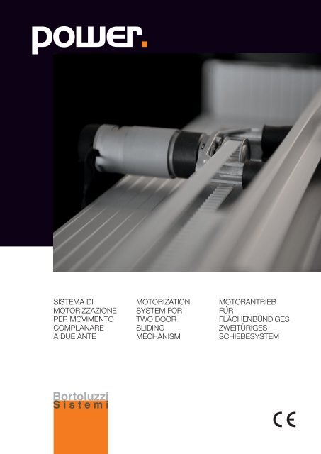
Sistema <strong>di</strong><br />
<strong>motorizzazione</strong><br />
<strong>per</strong> <strong>movimento</strong><br />
<strong>complanare</strong><br />
a <strong>due</strong> <strong>ante</strong><br />
Motorization<br />
system for<br />
two door<br />
Sli<strong>di</strong>ng<br />
mechanism<br />
Motorantrieb<br />
für<br />
flächenbün<strong>di</strong>ges<br />
zweitüriges<br />
Schiebesystem
Scheda tecnica del prodotto / Product technical sheet / Technische Beschreibung<br />
Il sistema <strong>di</strong> <strong>motorizzazione</strong> è un<br />
integrazione al sistema <strong>di</strong> scorrimento<br />
<strong>complanare</strong> a <strong>due</strong> <strong>ante</strong>.<br />
Si tratta infatti <strong>di</strong> un sistema<br />
che <strong>per</strong>mette <strong>di</strong> movimentare<br />
elettronicamente le <strong>ante</strong> a mezzo <strong>di</strong><br />
un’iniziale spinta manuale esercitata<br />
sulle maniglie dell’anta, oppure<br />
opzionalmente:<br />
• tramite telecomando<br />
• tramite pressione esercitata<br />
sull’anta in prossimità dei fianchi<br />
(in a<strong>per</strong>tura)<br />
E’ possibile richiedere l’applicazione<br />
della Motorizzazione sui<br />
meccanismi:<br />
• Slider M35<br />
• Slider S20 Pensile<br />
• Slider S20 Ma<strong>di</strong>a<br />
Profon<strong>di</strong>tà minima arma<strong>di</strong>o:<br />
• Slider M35 + Motorizzazione mm<br />
395<br />
• Slider S20 Pensile +<br />
Motorizzazione mm 340<br />
• Slider S20 Ma<strong>di</strong>a +<br />
Motorizzazione mm 340<br />
Peso massimo anta 35kg<br />
• Slider M35 - 35KG<br />
• Slider S20 Pensile - 20kg<br />
• Slider S20 Ma<strong>di</strong>a - 20kg<br />
The Motorised system is an integration<br />
to the two-door coplanar sli<strong>di</strong>ng<br />
mechanism.<br />
This system <strong>per</strong>mits electronically<br />
moving the doors by means of an initial<br />
manual push exercised on the door<br />
handles or, optionally:<br />
• by means of a remote control<br />
• by exercising a pressure on the<br />
door close to the sides (opening)<br />
It is possible to require the<br />
motorization of the following<br />
mechanism:<br />
• Slider M35<br />
• Slider S20 Wall cabinet<br />
• Slider S20 Floor Cabient<br />
Minimum cabinet depth:<br />
• Slider M35 + Motorization mm<br />
395<br />
• Slider S20 Wall Cabinet +<br />
Motorization mm 340<br />
• Slider S20 Floor Cabinet +<br />
Motorization mm 340<br />
Maximun door weight<br />
• Slider M35 - 35KG<br />
• Slider S20 Wall cabinet - 20kg<br />
• Slider S20 Floor cabinet - 20Kg<br />
Der Elektroantrieb ist eine Ergänzung<br />
des Flächenbün<strong>di</strong>gen Beschlages.<br />
Dieses System ermöglicht <strong>di</strong>e elektrische<br />
Öffnung der Türen durch einen leichten<br />
Druck auf den Griff, oder wahlweise auch<br />
durch:<br />
• Fernbe<strong>di</strong>enung<br />
• leichten Druck auf <strong>di</strong>e Außenk<strong>ante</strong><br />
der Türen (Öffnung) = Push<br />
Der Elektorantrieb kann für folgende<br />
Beschläge angefragt werden:<br />
• Slider M35<br />
• Slider S20 Unterschrank<br />
• Slider S20 Oberschrank.<br />
Mindestkorpustiefe:<br />
• Slider M35 + Elektroantrien mm<br />
395<br />
• Slider S20 Oberschrank +<br />
Elektroantrieb mm 340<br />
• Slider S20 Unterschrank +<br />
Elektroantrieb mm 340<br />
Maximales Türgewicht:<br />
• Slider M35 - 35kG<br />
• Slider S20 Unterschrank - 20kg<br />
• Slider S20 Oberschrank - 20kg<br />
POWER 3
Sistema <strong>di</strong> <strong>motorizzazione</strong> / Motorisation system / Motorantrieb<br />
D<br />
F<br />
E<br />
B<br />
B<br />
A<br />
C<br />
A<br />
1<br />
1- Meccanismo scorrevole fornito<br />
completo <strong>di</strong> motori e cinghie <strong>di</strong><br />
trascinamento.<br />
A- Sistema <strong>per</strong> la movimentazione<br />
delle <strong>ante</strong> composto da cinghie dentate<br />
metriche, ruote <strong>di</strong> scorrimento, elementi<br />
pressofusi in zama primaria 15, <strong>per</strong>ni,<br />
lamiere zincate, supporti antivibranti.<br />
B- Due motori DC con riduttore<br />
epicicloidale, encoder, puleggia<br />
dentata, cavo dotato <strong>di</strong> connettore a<br />
sgancio rapido <strong>di</strong> lunghezza 180 cm.<br />
C- Centralina elettronica <strong>di</strong> controllo<br />
a microprocessore con ingressi a<br />
connettore <strong>per</strong> motori, alimentazione e<br />
pulsanti <strong>di</strong> comando ausiliari; puls<strong>ante</strong><br />
unico reset/setup.<br />
D- Alimentatore con cavo <strong>di</strong><br />
collegamento alla rete <strong>di</strong> lunghezza<br />
200 cm e cavo <strong>di</strong> collegamento alla<br />
centralina dotato <strong>di</strong> connettore a<br />
sgancio rapido <strong>di</strong> lunghezza 300 cm.<br />
Optional<br />
E- Coppia <strong>di</strong> pulsanti luminosi da<br />
inserire nel fianco esterno con cavi<br />
<strong>di</strong> collegamento alla centralina dotati<br />
<strong>di</strong> connettore a sgancio rapido <strong>di</strong><br />
lunghezza 320 cm.<br />
1- Sli<strong>di</strong>ng mechanism complete of<br />
motors and drive belts already installed<br />
A- System for moving doors consisting<br />
of metric positive drive belts, sli<strong>di</strong>ng<br />
wheels, <strong>di</strong>e-cast parts in zama primary<br />
15, pin, galvanised plating, antivibration<br />
supports.<br />
B- Two DC motors with epicyclical<br />
reduction unit, encoder, toothed pulley,<br />
cable featuring rapid release connector,<br />
180 cm long<br />
C- Microprocessor electronic control<br />
unit with connector inputs for motors,<br />
power supply and auxiliary control<br />
buttons; single reset/set up button.<br />
D- Supply unit with 200 cm long<br />
lead for connecting to mains and<br />
unit connection cable featuring rapid<br />
release connector 300 cm long.<br />
Optional<br />
E- Pair of light buttons to be fitted on<br />
outer side with connection cables to<br />
unit featuring rapid release connector,<br />
320 cm long<br />
F- Remote control featuring remote<br />
control unit (and relevant support with<br />
wall magnet) and receiver fitted in unit<br />
1- Beschlag komplett montiert, mit<br />
Elektromotoren und Zahnriehmen.<br />
A-System für <strong>di</strong>e Bewegung der<br />
Türen bestehend aus Teilen in<br />
Zamakdruckguss: Zahnriemen,<br />
Kugellagern, Laufrollen, Zapfen,<br />
Verzinktes Blech, Antivibrationshalter.<br />
B-Zwei Wechselstrom-Motoren mit<br />
epyzyklischem Reduktor, Zahnriemen,<br />
Encoder, Riemenscheibe,<br />
Kabel mit Schnellverbinder in Länge<br />
180 cm.<br />
C-Steuerbüchse mit Mikroprozessor<br />
mit Eingänge zur Verbindung mit Motor,<br />
Netzanschluss, Schalter für Türöffnung,<br />
Setup/Reset Schalter.<br />
D-Netzanschlussgerät mit Kabel für<br />
den Stromanschluss (300 cm ) und<br />
Kabel mit Schnellverbinder (200 cm)<br />
Extra:<br />
E-Ein Paar beleuchtete Schalter<br />
mit Kabel 320 cm lang, mit<br />
Schnellverbindung. Zu montieren in<br />
den Außenseiten des Korpusses.<br />
F-Funksteuerung bestehend aus<br />
Fernbe<strong>di</strong>enung ( mit Magnethalter) und<br />
Empfänger (in Steuerbox integriert).<br />
4<br />
F- Ra<strong>di</strong>ocomando composto da<br />
telecomando (e relativo supporto con<br />
magnete a muro) e ricevente inserita<br />
nella centralina.<br />
Bortoluzzi Sistemi
Caratteristiche generali / General features / Beschreibung<br />
SOFTWARE<br />
• Movimentazione delle <strong>ante</strong> in chiusura<br />
ed in a<strong>per</strong>tura a mezzo <strong>di</strong> una spinta<br />
manuale iniziale.<br />
• Movimentazione delle <strong>ante</strong> in chiusura<br />
ed in a<strong>per</strong>tura a mezzo telecomando<br />
(opzionale).<br />
• Movimentazione delle <strong>ante</strong> in a<strong>per</strong>tura<br />
a mezzo pressione esercitata sull’anta<br />
in prossimità dei fianchi (opzionale).<br />
• Comando <strong>di</strong> reset/setup <strong>per</strong><br />
configurazione sistema ed<br />
autoappren<strong>di</strong>mento delle posizioni <strong>di</strong><br />
chiusura, <strong>di</strong> massima a<strong>per</strong>tura e <strong>di</strong><br />
lunghezza e peso dell’anta.<br />
• Dispositivo <strong>di</strong> sicurezza<br />
antischiacciamento con rilascio<br />
ostacolo me<strong>di</strong><strong>ante</strong> inversione del<br />
<strong>movimento</strong>.<br />
• Soft start con rampa <strong>di</strong> accelerazione.<br />
• Soft stop.<br />
SOFTWARE<br />
• Opening and closing door movement<br />
by means of an initial manual push.<br />
• Opening and closing door movement<br />
by means of remote control (optional).<br />
• Door opening movement by means of<br />
pressure exercised on door near sides<br />
(optional).<br />
• Reset/set up control for system<br />
configuration and self-learning of<br />
closing, max opening positions, and<br />
door length and weight.<br />
• Anti-trapping safety device with<br />
obstacle release by means of<br />
movement reversal.<br />
• Soft start with acceleration ramp.<br />
• Soft stop.<br />
SOFTWARE<br />
• Bewegung der Türen durch leichten<br />
Handdruck.<br />
• Bewegung der Türen durch<br />
Fernbe<strong>di</strong>enung (extra).<br />
• Bewegung der Türen durch Druck auf<br />
Türaußenk<strong>ante</strong>n (extra) .<br />
• Reset/Setup Steuerung und<br />
Selbstlernprozedur für <strong>di</strong>e<br />
Öffnungsposition der Türen, deren<br />
Gewicht und Länge.<br />
• Sicherheitsvorrichtung gegen<br />
Zerquetschen. Bei Hindernissen wird<br />
<strong>di</strong>e Fahrtrichtung umgekehrt.<br />
• Soft Start mit progressiver<br />
Beschleunigung<br />
• Soft stop<br />
HARDWARE<br />
Alimentatore<br />
- Trasformatore con protezione termica<br />
- Input 230VAC/50Hz<br />
- Output 18VAC/Potenza 40VA<br />
Centralina<br />
- input alimentazione (con fusibile):<br />
18VAC<br />
- output ai motori: 5V DC<br />
(alimentazione sensori encoder),<br />
25V DC (tensione massima ai motori)<br />
Motoriduttori<br />
- Coppia nominale: 2,3 kgcm<br />
- Velocità nominale: 375 rpm<br />
- Alimentazione: 24V DC<br />
- Corrente nominale: 750mA<br />
- Potenza nominale: 12,70W<br />
Ricevitore Nice<br />
- Alimentazione 10-28V DC<br />
- Trasmettitore Nice<br />
- Alimentazione 3V, con batteria tipo<br />
CR2032<br />
- Frequenza <strong>di</strong> trasmissione:<br />
433.92MHz<br />
- Potenza irra<strong>di</strong>ata: 100mW<br />
Pulsanti<br />
- Alimentazione luce 5V DC<br />
HARDWARE<br />
Supply unit<br />
- Transformer with thermal cutout<br />
- Input 230VAC/50Hz<br />
- Output 18VAC/Power 40VA<br />
Control unit<br />
- supply input (with fuse): 18VAC<br />
- output to motors: 5V DC (encoder<br />
sensor supply), 25V DC (max voltage<br />
to motors)<br />
Gearmotors<br />
- Nominal torque: 2.3 kgcm<br />
- Nominal speed: 375 rpm<br />
- Power supply: 24V DC<br />
- Nominal current: 750mA<br />
- Rated power: 12.70W<br />
Nice Receiver<br />
- Power supply 10-28V DC<br />
- Nice transmitter<br />
- Power supply 3V, with battery type<br />
CR2032<br />
- Transmission frequency 433.92MHz<br />
- Irra<strong>di</strong>ated power: 100mW<br />
Buttons<br />
- Light power supply 5V DC<br />
HARDWARE:<br />
Netzanschlussgerät<br />
- Transformator mit Wärmeschutz<br />
- Input 230 VAC / 50Hz<br />
- Output 18 VAC/ Leistung 40 VA<br />
Schaltbuchse<br />
- Eingang Stromversorgung (mit<br />
Schmelzsicherung): 18 VAC<br />
- Ausgang zu Motoren: 5V DC<br />
(Versorgung der Sensoren) 25V DC<br />
(maximale Spannung auf Motoren)<br />
Untersetzungsgetriebe<br />
- Nominaler Drehmoment: 2,3 kgcm<br />
- Nominale Geschwin<strong>di</strong>gkeit: 375 U/<br />
min<br />
- Stromversorgung 24V DC<br />
- Nominale Spannung 750 mA<br />
- Nominale Leistung 12,70W<br />
Empfänger (Nice)<br />
- Stromversorgung 10-28 V DC<br />
- Überträger (Nice)<br />
- Versorgung über 3 V mit Batterien<br />
typCR2032<br />
- Übertragungsfrequenz 433.92 MHz<br />
- Ausgestrahlte Leistung<br />
Schalter:<br />
- Stromversorgung für Beleuchtung: 5V<br />
DC<br />
POWER 5
Settaggio del sistema / System setting / Einstellung des Systems<br />
G<br />
H<br />
Dopo aver completato il montaggio del<br />
sistema e la regolazione dell’arma<strong>di</strong>o<br />
come da in<strong>di</strong>cazioni riportate nel<br />
manuale standard è necessario eseguire<br />
il set up <strong>per</strong> l’autoappren<strong>di</strong>mento del<br />
sistema tenendo premuto <strong>per</strong> alcuni<br />
secon<strong>di</strong> il puls<strong>ante</strong> RS posto nella parte<br />
posteriore della centralina (G).<br />
L’autoappren<strong>di</strong>mento si completerà<br />
grazie all’a<strong>per</strong>tura/chiusura prima<br />
dell’anta sinistra e successivamente<br />
dell’anta destra.<br />
Opzionalmente il set up può essere<br />
attivato anche tramite telecomando<br />
tenendo premuto <strong>per</strong> cinque secon<strong>di</strong><br />
il puls<strong>ante</strong> “2” (H); questa soluzione<br />
è consigliata al clienti che avranno<br />
un <strong>di</strong>fficile accesso alla centralina (ad<br />
esempio mobili incassati).<br />
Il set up può essere eseguito o con<br />
entrambe le <strong>ante</strong> chiuse oppure con<br />
l’anta sinistra a<strong>per</strong>ta.<br />
After assembling the system and<br />
regulating the wardrobe as <strong>per</strong><br />
instructions provided in the standard<br />
manual, the set up will have to be<br />
<strong>per</strong>formed for system self-learning by<br />
keeping the button RS on the rear of<br />
the control unit (G) pressed for a few<br />
seconds. Self-learning will be completed<br />
thanks to the opening/closing first of all<br />
of the left door and then of the right door.<br />
Alternatively, the set up can be<br />
<strong>per</strong>formed by means of the remote<br />
control, keeping the button “2” (H)<br />
pressed for five seconds. This solution<br />
is preferable for customers who cannot<br />
easily access the control unit (e.g., fitted<br />
furniture).<br />
The set up can either be <strong>per</strong>formed with<br />
both doors closed or with the left door<br />
open.<br />
Nach der Montage des Beschlages<br />
und dessen Feineinstellung,<br />
wie im Handbuch des Standard<br />
SliderMe<strong>di</strong>um beschrieben, muss<br />
<strong>di</strong>e Selbstlernprozedur durchgeführt<br />
werden. Der R/S Knopf, der sich auf der<br />
Rückseite der Schaltbuchse (G) einige<br />
Sekunden halten.<br />
Während der Prozedur wird erst <strong>di</strong>e<br />
Linke, dann <strong>di</strong>e rechte Türe einmal<br />
geöffnet und wieder geschlossen.<br />
Diese Prozedur kann auch durch <strong>di</strong>e<br />
Fernbe<strong>di</strong>enung gesteuert werden. Dafür<br />
den Knopf 2, fünf Sekunden langhalten<br />
(H). Diese Lösung ist geeignet falls <strong>di</strong>e<br />
Schaltbox schwer zu erreichen ist.<br />
Das Set-up kann bei geschlossen Türen<br />
oder bei offener linker Tür durchgeführt<br />
werden.<br />
6<br />
Bortoluzzi Sistemi
Sistema <strong>di</strong> <strong>movimento</strong> / Movement system / Möglichkeiten der Öffnung-Schließung<br />
In a<strong>per</strong>tura la movimentazione<br />
dell’anta può essere avviata:<br />
• Tramite spinta manuale (N).<br />
• Opzionalmente tramite telecomando<br />
(P), rispettivamente premendo il<br />
“puls<strong>ante</strong> 1” <strong>per</strong> l’anta sinistra e<br />
premendo il “puls<strong>ante</strong> 3” <strong>per</strong> l’anta<br />
destra.<br />
• Opzionalmente tramite pressione<br />
esercitata sull’anta in prossimità<br />
dei fianchi ove andranno incassati i<br />
pulsanti. (Q)<br />
The door opening movement can be<br />
started:<br />
• By manual push (N).<br />
• Alternatively, by remote control (P),<br />
by pressing “button 1” for the left<br />
door and “button 3” for the right<br />
door respectively.<br />
• Alternatively, by exercising a<br />
pressure on the door close to the<br />
sides where the buttons (Q) are<br />
recessed<br />
Die Öffnung der Türen kann in<br />
folgender Weise erfolgen:<br />
• Durch manuellen Zug (N).<br />
• Alternativ mit Fernbe<strong>di</strong>enung (P) -<br />
Taste “1” für linke Türe und Taste<br />
“3” für rechte Türe. (Fernbe<strong>di</strong>enung<br />
muss separat bestellt werden)<br />
• Oder durch einen Druck auf<br />
Türaußenk<strong>ante</strong> (Q), auf <strong>di</strong>e darunter<br />
liegenden Schalter (muss separat<br />
bestellt werden).<br />
N P Q<br />
In chiusura la movimentazione<br />
dell’anta può essere avviata:<br />
• Tramite spinta manuale (R).<br />
• Opzionalmente tramite telecomando<br />
(S), rispettivamente premendo il<br />
“puls<strong>ante</strong> 1” <strong>per</strong> l’anta sinistra e<br />
premendo il “puls<strong>ante</strong> 3” <strong>per</strong> l’anta<br />
destra.<br />
• Opzionalmente tramite pressione<br />
esercitata sul puls<strong>ante</strong> incassato nel<br />
fianco. (T)<br />
The door closing movement can be<br />
started:<br />
• By manual push (R).<br />
• Alternatively, by remote control (S),<br />
by pressing “button 1” for the left<br />
door and “button 3” for the right<br />
door respectively.<br />
• Alternatively, by exercising a<br />
pressure on the button recessed in<br />
the side (T)<br />
Die Schließung der Türen kann<br />
folgender Weise erfolgen:<br />
• Durch manuellen Druck (R).<br />
• Alternativ mit Fernbe<strong>di</strong>enung (S),<br />
Taste “1” für linke Türe und Taste “3”<br />
für rechte Türe.<br />
• Alternativ auch durch einen<br />
Druck auf <strong>di</strong>e in den Außenseiten<br />
montierten Schalter (T).<br />
R S T<br />
POWER 7
Installazione pulsanti / Light buttons installation / Einstellung der Schalter<br />
M<br />
Il cliente che lo desidera riceverà<br />
una coppia <strong>di</strong> pulsanti luminosi ver<strong>di</strong><br />
(L) (con cavi <strong>di</strong> collegamento alla<br />
centralina dotati <strong>di</strong> connettore a sgancio<br />
rapido) da inserire nei fianchi esterni<br />
precedentemente lavorati.<br />
I connettori a sgancio rapido dovranno<br />
essere inseriti negli ingressi della<br />
centralina contrad<strong>di</strong>stinti dalla targhetta<br />
“P” e specificatamente nell’ingresso “P1”<br />
il cavo il cui puls<strong>ante</strong> verrà inserito nel<br />
fianco esterno sinistro e nell’ingresso<br />
“P2” il cavo il cui puls<strong>ante</strong> verrà inserito<br />
nel fianco esterno destro (M).<br />
The customer who so wishes will receive<br />
a pair of green light buttons (L) (with<br />
leads for connecting to the control unit<br />
featuring rapid-release connector) to<br />
be fitted in the previously worked outer<br />
sides.<br />
The rapid-release connectors must be<br />
fitted in the control unit inputs marked by<br />
plate “P” and more specifically in input<br />
“P1” the lead whose button is fitted in<br />
the left outer side and in input “P2” the<br />
lead whose button is fitted in the right<br />
outer side (M).<br />
Für <strong>di</strong>e Be<strong>di</strong>enung der Türen mit<br />
leichtem Druck auf <strong>di</strong>e Aussenk<strong>ante</strong><br />
(=Push) müssen <strong>di</strong>e Schalter (L) mit der<br />
Schnellverbindung zur Schaltbuchse<br />
in <strong>di</strong>e dazu vorbereitete Außenseiten<br />
montiert werden.<br />
Die Verbindungen müssen dann durch<br />
<strong>di</strong>e Eingänge mit der Beschriftung “P”<br />
an <strong>di</strong>e Schaltbuchseverbunden werden<br />
und zwar der Schalter der in <strong>di</strong>e linke<br />
Seite eingearbeitet wird in Eingang “P1”<br />
und der Schalter der in <strong>di</strong>e rechte Seite<br />
eingearbeitet wird in Eingang “P2” (M).<br />
L<br />
ø 16<br />
8<br />
Bortoluzzi Sistemi
Installazione Ra<strong>di</strong>ocomando / Remote-control installation / Einstellung der Fernbe<strong>di</strong>enung<br />
Il cliente che lo desidera potrà decidere<br />
<strong>di</strong> integrare il ra<strong>di</strong>ocomando composto<br />
da telecomando (e relativo supporto con<br />
magnete a muro) e ricevente.<br />
The customer who so wishes can decide<br />
to integrate the remote control unit<br />
made up of remote control (and relevant<br />
support with wall magnet) and receiver.<br />
Optional können <strong>di</strong>e Türen durch<br />
eine Funksteuerung, bestehend aus<br />
Fernbe<strong>di</strong>enung (mit Magnethalter) und<br />
Empfänger (in Steuerbox integriert)<br />
be<strong>di</strong>ent werden.<br />
2 3 4<br />
Quando si attiva la fase <strong>di</strong> memorizzazione,<br />
qualsiasi trasmettitore correttamente<br />
riconosciuto nel raggio <strong>di</strong> ricezione della<br />
ra<strong>di</strong>o viene memorizzato. Valutare con<br />
attenzione questo aspetto.<br />
• Disattivare l’alimentazione elettrica.<br />
• Svitare le viti e togliere il co<strong>per</strong>chio della<br />
scatola della centralina. (2)<br />
• Inserire il ricevitore<br />
nell’apposito connettore all’interno della<br />
centralina (3).<br />
• Riattivare l’alimentazione elettrica.<br />
• Premere e tenere premuto il puls<strong>ante</strong><br />
sul ricevitore <strong>per</strong> almeno tre secon<strong>di</strong>;<br />
quando il Led sul ricevitore si accende<br />
rilasciare il puls<strong>ante</strong>. (4)<br />
Once the storage phase has started,<br />
any transmitter correctly recognised<br />
within the reception range of the ra<strong>di</strong>o is<br />
stored. Carefully assess this aspect.<br />
• Disconnect the power supply.<br />
• Loosen the screws and remove the<br />
cover of the box of the control unit. (2)<br />
• Insert the receiver in the connector<br />
inside the control unit (3).<br />
• Restore the power supply.<br />
• Press the button on the receiver and<br />
keep it pressed for at least three<br />
seconds; when the LED on the receiver<br />
comes on, release the button. (4)<br />
Bitte beachten: während der<br />
Programmierphase, werden alle<br />
Fernbe<strong>di</strong>enungen, <strong>di</strong>e im Funkbereich<br />
des Empfängers sich befinden,<br />
umprogrammiert !<br />
• Die Stromversorgung abschalten (1)<br />
• Deckel der Schaltbuchse<br />
abschrauben (2)<br />
• Empfänger an den Verbinder<br />
anschließen (3)<br />
• Stromverbindung anschließen<br />
• Den Schalter auf dem Empfänger<br />
mindestens 3 Sekunden lang halten;<br />
wenn <strong>di</strong>e LED auf dem Empfänger<br />
aufleuchtet - den Schalter loslassen.(4)<br />
POWER 9
Installazione Ra<strong>di</strong>ocomando / Remote-control installation / Einstellung Fernbe<strong>di</strong>enung<br />
5 6 7<br />
• Premere e tenere premuto il “puls<strong>ante</strong><br />
1” sul telecomando; quando il Led sul<br />
ricevitore inizia a lampeggiare rilasciare<br />
il puls<strong>ante</strong>. (5)<br />
• Quando il led sul ricevitore ha<br />
smesso <strong>di</strong> lampeggiare premere e<br />
tenere premuto il “puls<strong>ante</strong> 2” sul<br />
telecomando; quando il Led sul<br />
ricevitore inizia a lampeggiare rilasciare<br />
il puls<strong>ante</strong>. (6)<br />
• Quando il led sul ricevitore ha<br />
smesso <strong>di</strong> lampeggiare premere e<br />
tenere premuto il “puls<strong>ante</strong> 3” sul<br />
telecomando; quando il Led sul<br />
ricevitore inizia a lampeggiare rilasciare<br />
il puls<strong>ante</strong>. (7)<br />
• Attendere che il led sul ricevitore si<br />
accenda <strong>per</strong> alcuni secon<strong>di</strong>.<br />
• Reinserire il co<strong>per</strong>chio della scatola<br />
della centralina e riavvitare le viti.<br />
• Eseguire il set-up<br />
• Press the “button 1” on the remote<br />
control and keep it pressed; when the<br />
LED on the receiver starts to flash,<br />
release the button. (5)<br />
• When the LED on the receiver stops<br />
flashing, press the “button 2” on the<br />
remote control and keep it pressed;<br />
when the LED on the receiver starts to<br />
flash, release the button. (6)<br />
• When the LED on the receiver has<br />
stopped flashing, press the “button<br />
3” on the remote control and keep it<br />
pressed; when the LED on the receiver<br />
starts to flash, release the button (7).<br />
• Wait for the LED on the receiver to light<br />
up for a few seconds.<br />
• Reposition the cover of the control unit<br />
box and tighten the screws.<br />
• Perform the set-up<br />
• Den Schalter “1” auf der<br />
Fernbe<strong>di</strong>enung drücken bis <strong>di</strong>e LED<br />
auf dem Empfänger zu blinken beginnt,<br />
dann Schalter loslassen. (5)<br />
• Wenn <strong>di</strong>e LED auf dem Empfänger<br />
nicht mehr blink, Schalter “2” auf der<br />
Fernbe<strong>di</strong>enung drücken bis <strong>di</strong>e LED<br />
auf dem Empfänger zu blinken beginnt,<br />
dann Schalter loslassen (6)<br />
• Wenn <strong>di</strong>e LED auf dem Empfänger<br />
nicht mehr blink, Schalter “3” auf der<br />
Fernbe<strong>di</strong>enung drücken bis <strong>di</strong>e LED<br />
auf dem Empfänger zu blinken beginnt,<br />
dann Schalter loslassen. (7)<br />
• Warten bis <strong>di</strong>e LED einige Sekunden<br />
leuchtet.<br />
• Deckel der Buchse aufsetzen und<br />
anschrauben.<br />
• Set-up durchführen.<br />
10<br />
Bortoluzzi Sistemi
Sostituzione motoriduttore / Gearmotor Replacement / Austauscher der Untersetzungsgetriebe<br />
• Disattivare l’alimentazione elettrica.<br />
• Estrarre il connettore a sgancio rapido<br />
del cavo del motore dall’ingresso della<br />
centralina (U).<br />
• Disconnect the power supply.<br />
• Remove the rapid release connector of<br />
the motor lead from the control unit (U)<br />
input.<br />
• Stromversorgung abschalten.<br />
• Den Verbindungen des Motors mit der<br />
Schaltbuchse lösen. (U)<br />
U<br />
V<br />
V<br />
• Allentare la viti M5x8 TCEI dell’elemento<br />
ten<strong>di</strong>tore e spostare quest’ultimo al fine<br />
<strong>di</strong> allentare la cinghia (V).<br />
• Svitare le viti M6x35 TPSEI<br />
(oppure M6x12 TPSEI nel caso del<br />
motoriduttore interno) ed estrarre il<br />
motoriduttore comprensivo <strong>di</strong> piastra <strong>di</strong><br />
fissaggio (Z).<br />
• Eseguire la sostituzione del blocco<br />
motoriduttore-piastra <strong>di</strong> fissaggio<br />
completando i punti nel senso inverso<br />
rispetto all’estrazione.<br />
• Riattivare l’alimentazione elettrica.<br />
• Eseguire il set-up.<br />
• Loosen the M5x8 socket cap screws of<br />
the tightener and move the latter so as<br />
to slacken the belt (V).<br />
• Loosen the M6x35 socket countersunk<br />
screws (or M6x12 socket countersunk<br />
screws in the case of the inner<br />
gearmotor) and remove the gearmotor<br />
complete with fastening plate (Z).<br />
• Replace the gearmotor-fastening plate<br />
assembly by procee<strong>di</strong>ng in reverse<br />
sequence with respect to removal.<br />
• Reconnect the power supply.<br />
• Perform set-up.<br />
• Die Schrauben M5x8 der<br />
Spannvorrichtung entfernen und <strong>di</strong>esen<br />
bewegen um den Zahnriemen zu<br />
lockern (V).<br />
• Die Schrauben M6x12 (oder<br />
M6x12 im Falle des inneren<br />
Untersetzungsgetriebes) und das<br />
Getriebe mit dem Befestigungssockel<br />
entfernen (Z).<br />
• Das Getriebe und den Sockel<br />
austauschen und <strong>di</strong>e oben<br />
beschriebene Prozedur in umgekehrter<br />
Reihenfolge durchführen.<br />
• Stromanschluss wieder anschließen.<br />
• Set-up durchführen.<br />
Z<br />
Z<br />
Z<br />
POWER 11
Sostituzione centralina / Control unit replacement / Austauscher der Schaltbuchse<br />
• Disattivare l’alimentazione elettrica<br />
• Staccare tutti i cavi (che sono dotati <strong>di</strong><br />
connettori a sgancio rapido) fissati alla<br />
centralina.<br />
• Eseguire la sostituzione della centralina<br />
prestando attenzione che:<br />
- i connettori a sgancio rapido dei<br />
motoriduttori dovranno essere<br />
inseriti negli ingressi della centralina<br />
contrad<strong>di</strong>stinti dalla targhetta “M” e<br />
specificatamente nell’ingresso “M1”<br />
il cavo del motore dell’anta sinistra (e<br />
posto a sinistra) e nell’ingresso “M2”<br />
il cavo del motore dell’anta destra (e<br />
posto a destra).<br />
- i connettori a sgancio rapido dei<br />
pulsanti luminosi dovranno essere<br />
inseriti negli ingressi della centralina<br />
contrad<strong>di</strong>stinti dalla targhetta “P” e<br />
specificatamente nell’ingresso “P1” il<br />
cavo il cui puls<strong>ante</strong> verrà inserito nel<br />
fianco esterno sinistro e nell’ingresso<br />
“P2” il cavo il cui puls<strong>ante</strong> verrà<br />
inserito nel fianco esterno destro.<br />
- il connettore a sgancio rapido<br />
dell’alimentazione dovrà essere<br />
inserito nell’ ingresso della centralina<br />
contrad<strong>di</strong>stinto dalla targhetta “A”.<br />
• Riattivare l’alimentazione elettrica.<br />
• Eseguire il set-up.<br />
• Disconnect the power supply<br />
• Disconnect all the leads (which feature<br />
rapid-release connectors) fastened to<br />
the control unit.<br />
• Replace the control unit, being careful<br />
that:<br />
- the rapid-release connectors of the<br />
gearmotors must be fitted in the<br />
control unit inputs marked by the<br />
plate “M” and more specifically, the<br />
lead of the left door motor (on the left)<br />
in the “M1” input and the lead of the<br />
right door motor (on the right) in the<br />
“M2” input.<br />
- the rapid-release connectors of the<br />
light buttons must be fitted in the<br />
control unit inputs marked by the<br />
plate “P” and more specifically, the<br />
lead whose button is to be fitted in<br />
the outer left side in the “P1” input<br />
and the lead whose button is to be<br />
fitted in the outer right side in the “P2”<br />
input.<br />
- the rapid-release connector of the<br />
supply unit must be fitted in the<br />
control unit input marked by the plate<br />
“A”.<br />
• Reconnect the power supply.<br />
• Perform set-up.<br />
• Stromversorgung abschalten.<br />
• Alle Kabel (<strong>di</strong>e mit Schnellverbindern<br />
ausgestattet sind) von der<br />
Schaltbuchse lösen.<br />
• Die Ersetzung der Buchse durchführen<br />
und dabei beachten:<br />
- Die Verbindungen zu den Getrieben<br />
müssen in <strong>di</strong>e Eingänge mit der<br />
Beschriftung “M” eingesetzt werden:<br />
in Eingang “M1” <strong>di</strong>e <strong>di</strong>e Kabel des<br />
Motors für <strong>di</strong>e linke Türe (der sich<br />
links befindet) und in Eingang “M2”<br />
<strong>di</strong>e Kabel für den Motor der rechte<br />
Türe (der sich rechts befindet).<br />
- Die Kabel der Schalter müssen in <strong>di</strong>e<br />
Eingänge mit der Beschriftung “P” an<br />
<strong>di</strong>e Schaltbuchseeingesetzt werden.<br />
Der Schalter der in <strong>di</strong>e linke Seite<br />
eingearbeitet wird in Eingang “P1”<br />
und der Schalter der in <strong>di</strong>e rechte<br />
Seite eingearbeitet wird in Eingang<br />
“P2” (M).<br />
- Das Kabel für den Stromanschluss<br />
muss in den Eingang mit der<br />
Beschriftung “A” eingesetzt werden.<br />
• Stromanschluss wieder anschließen.<br />
• Set-up durchführen.<br />
12<br />
Bortoluzzi Sistemi
Modalità <strong>di</strong> utilizzo / O<strong>per</strong>ating procedure / Benutzungshinweise<br />
• L’installazione del sistema (comprensiva<br />
del fissaggio delle <strong>ante</strong>) deve essere<br />
eseguita solo da <strong>per</strong>sonale qualificato<br />
in grado <strong>di</strong> rispettare le normative<br />
nazionali/internazionali vigenti.<br />
• L’intervento <strong>di</strong> assistenza tecnica deve<br />
essere eseguito solo da <strong>per</strong>sonale<br />
qualificato in grado <strong>di</strong> rispettare le<br />
normative nazionali/internazionali vigenti.<br />
• L’installazione del sistema deve essere<br />
eseguita facendo accurato riferimento<br />
alle note <strong>di</strong> montaggio in<strong>di</strong>cate in<br />
questo manuale.<br />
• L’installazione del sistema deve essere<br />
eseguita in modo da evitare qualsiasi<br />
contatto con liqui<strong>di</strong><br />
• L’installazione del sistema deve essere<br />
eseguita in assenza della tensione <strong>di</strong> rete.<br />
• L’alimentazione del sistema deve<br />
essere prelevata da un impianto<br />
elettrico costruito secondo le vigenti<br />
norme nazionali ed, in particolare, deve<br />
essere verificata la presenza, sula linea<br />
<strong>di</strong> alimentazione della centralina, <strong>di</strong> un<br />
<strong>di</strong>spositivo <strong>di</strong>fferenziale <strong>di</strong> protezione.<br />
• Questo sistema è stato progettato <strong>per</strong><br />
un uso non continuativo, in caso <strong>di</strong> uso<br />
continuativo questo non deve su<strong>per</strong>are<br />
i 15 minuti, dopo tale <strong>per</strong>iodo è<br />
necessario fare osservare al sistema un<br />
<strong>per</strong>iodo <strong>di</strong> riposo <strong>di</strong> almeno 15 minuti.<br />
• Non forzare il <strong>movimento</strong> delle <strong>ante</strong><br />
dur<strong>ante</strong> il moto.<br />
• Non azionare il sistema in presenza <strong>di</strong><br />
evidenti ostacoli.<br />
• Non <strong>per</strong>mettere l’utilizzo del sistema ai<br />
bambini senza la dovuta sorveglianza.<br />
• System installation (inclu<strong>di</strong>ng door<br />
fastening) must only be <strong>per</strong>formed by<br />
professional <strong>per</strong>sonnel able to observe<br />
applicable national/international<br />
regulations.<br />
• Technical assistance must only be<br />
provided by professional staff able<br />
to observe applicable national/<br />
international regulations.<br />
• The system must be installed making<br />
careful reference to the assembly notes<br />
in this manual.<br />
• The system must be installed in such<br />
a way as to avoid any contact with<br />
liquids.<br />
• During system installation, the power<br />
supply must be <strong>di</strong>sconnected.<br />
• The power supply must originate from<br />
a power plant built in accordance with<br />
applicable national standards and,<br />
in particular, the control unit power<br />
line must be equipped with a residual<br />
current circuit breaker.<br />
• This system has been designed for<br />
non-continuous use. In the event of<br />
continuous use, this should not exceed<br />
15 minutes. After such <strong>per</strong>iod, the<br />
system must be allowed to rest for at<br />
least 15 minutes.<br />
• Do not force the movement of the<br />
doors during movement.<br />
• Do not o<strong>per</strong>ate the system in the<br />
presence of evident obstacles.<br />
• Do not allow children to use the system<br />
without adequate su<strong>per</strong>vision<br />
• Die Montage des Beschlages (und<br />
der Türen) darf nur vom qualifizierten<br />
Personal durchgeführt werden, <strong>di</strong>e<br />
in der Lage sind <strong>di</strong>e nationalen und<br />
internationalen Normen einhalten zu<br />
können.<br />
• Der Kunden<strong>di</strong>enst darf nur vom<br />
qualifizierten Personal durchgeführt<br />
werden, <strong>di</strong>e in der Lage sind <strong>di</strong>e<br />
nationalen und internationalen Normen<br />
einhalten zu können.<br />
• Die Montage muss nach den Hinweisen<br />
<strong>di</strong>e in <strong>di</strong>esem Handbuch enthalten sind,<br />
erfolgen.<br />
• Bei der Montage des Beschlages<br />
muss der Kontakt mit Flüssigkeiten<br />
vermieden werden.<br />
• Bei der Montage muss beachten<br />
werden, dass <strong>di</strong>e Stromversorgung<br />
abgeschaltet ist.<br />
• Die Stromversorgung muss durch<br />
einen normgerechten Anschluss<br />
gewährleistet sein. Der über eine<br />
Sicherheitsvorrichtung gegen<br />
Spannungsabbruch verfügt.<br />
• Der Beschlag ist nicht für einen<br />
Dauergebrauch konstruiert. Die<br />
Laufzeit sollte <strong>di</strong>e 15 Minuten nicht<br />
überschreiten. Nach Überschreitung<br />
<strong>di</strong>eser Zeit, muss eine Ruhezeit von<br />
etwa 15 Minuten vorgesehen werden.<br />
• Wenn <strong>di</strong>e Türe in Bewegung ist, <strong>di</strong>ese<br />
nicht ziehen oder schieben.<br />
• Bei sichtlichen Hindernissen den<br />
Beschlag nicht betätigen.<br />
• Kinder sollten den Beschlag nur unter<br />
Aufsicht verwenden.<br />
POWER 13
Problemi e soluzioni / Troubleshooting / Probleme und Lösungsvorschläge<br />
Non parte il set up.<br />
- Attendere qualche secondo e ripetere<br />
il set up accertandosi <strong>di</strong> pigiare fino in<br />
fondo i pulsanti.<br />
- Verificare che la scheda sia alimentata<br />
correttamente.<br />
Il set up si interrompe dopo che una<br />
sola delle <strong>due</strong> <strong>ante</strong> si è spostata.<br />
- Verificare che i connettori ad innesto<br />
rapido dei motoriduttori siano<br />
correttamente inseriti negli ingressi<br />
della centralina. Ripetere il set up.<br />
Il set up si completa ma una o<br />
entrambe le <strong>ante</strong> non arrivano a<br />
finecorsa.<br />
- Verificare che mobile ed <strong>ante</strong> siano<br />
correttamente in bolla (ve<strong>di</strong> manuale<br />
meccanismo). Ripetere il set up.<br />
- Verificare che nessun ostacolo<br />
impe<strong>di</strong>sca il <strong>movimento</strong> delle <strong>ante</strong>.<br />
Ripetere il set up.<br />
- Verificare che su binario in alluminio<br />
o su guide in MDF non sia presente<br />
sporcizia che pregiu<strong>di</strong>chi lo<br />
scorrimento. Ripetere il set up.<br />
Entrambe le <strong>ante</strong> non si aprono o<br />
un’anta non si chiude nel caso fosse<br />
stata lasciata a<strong>per</strong>ta.<br />
- Verificare che la centralina sia<br />
alimentata correttamente. Ripetere il<br />
set up.<br />
- Verificare che i connettori ad innesto<br />
rapido dei motoriduttori siano<br />
correttamente inseriti negli ingressi<br />
della centralina. Ripetere il set up.<br />
- Sostituire la centralina e ripetere il<br />
set up.<br />
Un’anta non si apre o un’anta non si<br />
chiude nel caso fosse stata lasciata<br />
a<strong>per</strong>ta.<br />
- Verificare che il connettore ad<br />
innesto rapido del motoriduttore sia<br />
correttamente inserito nell’ ingressi<br />
della centralina. Ripetere il set up<br />
- Sostituire il motoriduttore. Ripetere il<br />
set up.<br />
Un’anta si muove molto lentamente.<br />
- Verificare che su binario in alluminio<br />
o su guide in MDF non sia presente<br />
sporcizia che pregiu<strong>di</strong>chi lo<br />
scorrimento. Ripetere il set up.<br />
- Verificare che mobile ed <strong>ante</strong> siano<br />
correttamente in bolla (ve<strong>di</strong> manuale<br />
meccanismo). Ripetere il set up.<br />
- Sostituire il motoriduttore. Ripetere il<br />
set up.<br />
The set up fails to start.<br />
- Wait a few seconds and repeat the<br />
set up, making sure the buttons are<br />
fully pressed.<br />
- Make sure the board is correctly<br />
supplied.<br />
The set up stops after only one of<br />
the doors has moved.<br />
- Make sure the quick-coupling<br />
connectors of the gearmotors are<br />
correctly fitted in the control unit<br />
inputs. Repeat set up.<br />
The set up is completed but one<br />
or both doors fail to reach end of<br />
stroke.<br />
- Make sure that unit and doors are<br />
pro<strong>per</strong>ly levelled (see mechanism<br />
manual). Repeat the set up.<br />
- Make sure there are no obstacles<br />
preventing door movement. Repeat<br />
the set up.<br />
- Make sure there is no <strong>di</strong>rt on the<br />
aluminium runner or MDF guides that<br />
prevents smooth sli<strong>di</strong>ng. Repeat set up.<br />
Neither doors open or a door fails to<br />
close if left open.<br />
- Make sure power is reaching the control<br />
unit correctly. Repeat the set up.<br />
- Make sure the quick-coupling<br />
connectors of the gearmotors are<br />
correctly fitted in the control unit<br />
inputs. Repeat set up.<br />
- Replace the control units and repeat<br />
set up.<br />
One door fails to open or a door fails<br />
to close if left open.<br />
- Make sure the quick-coupling<br />
connector of the gearmotor is<br />
correctly fitted in the control unit<br />
inputs. Repeat set up<br />
- Replace the gearmotor. Repeat set up.<br />
A door moves very slowly.<br />
- Make sure there is no <strong>di</strong>rt on the<br />
aluminium runner or on the MDF<br />
guides that prevents smooth sli<strong>di</strong>ng.<br />
Repeat set up.<br />
- Make sure the unit and doors are<br />
correctly levelled (see mechanism<br />
manual). Repeat set up.<br />
- Replace the gearmotor. Repeat set up.<br />
Set up startet nicht.<br />
- Einige Sekunden warten und <strong>di</strong>e<br />
Prozedur wiederholen. Sicherstellen<br />
dass <strong>di</strong>e Schalter richtig betätigt<br />
werden.<br />
- Kontrollieren dass der<br />
Stromanschluss richtig<br />
angeschlossen ist.<br />
Set up unterbricht sich nachdem nur<br />
eine Türe sich bewegt hat.<br />
- Kontrollieren das alle Kabel korrekt<br />
in <strong>di</strong>e Schaltbuchse eingesetzt sind.<br />
Set-up wiederholen.<br />
Set up wird durchgeführt aber<br />
eine oder beide Türen gehen nicht<br />
komplett auf.<br />
- Kontrollieren dass der Schrank<br />
<strong>per</strong>fekt ausgerichtet ist (siehe<br />
Mechanismus Handbuch). Set-up<br />
wiederhohlen.<br />
- Kontrollieren das keine Hindernisse<br />
in Laufweg der Türen liegt. Set-up<br />
wiederhohlen.<br />
- Kontrollieren das im Alu-profil oder<br />
in den MDF-Schienen kein Schmutz<br />
oder Staub liegen, <strong>di</strong>e <strong>di</strong>e Bewegung<br />
der Türen stören können. Set-up<br />
wiederhohlen.<br />
Beide Türen öffnen sich nicht oder<br />
eine der Türen schließt nicht mehr<br />
nachdem sie geöffnet wurde.<br />
- Kontrollieren ob der Stromanschluss<br />
an <strong>di</strong>e Schaltbuchse richtig<br />
angeschlossen ist.<br />
- Kontrollieren, ob alle Kabel der<br />
Getriebe korrekt in <strong>di</strong>e Schaltbuchse<br />
eingesetzt sind. Set-up wiederholen.<br />
- Schaltbuchse austauschen.<br />
Eine Türe öffnet sich nicht oder eine<br />
Türe schliesst nicht nachdem sie<br />
geöffnet wurde.<br />
- Kontrollieren, ob alle Kabel der<br />
Getriebe korrekt in <strong>di</strong>e Schaltbuchse<br />
eingesetzt sind. Set-up wiederholen.<br />
- Getriebe austauschen.<br />
Eine Türe öffnet sich nur sehr<br />
langsam.<br />
- Kontrollieren, ob im Alu-profil oder<br />
in den MDF-Schienen kein Schmutz<br />
oder Staub liegen, <strong>di</strong>e <strong>di</strong>e Bewegung<br />
der Türen stören können. Set-up<br />
wiederhohlen.<br />
- Kontrollieren, ob der Schrank <strong>per</strong>fekt<br />
ausgerichtet ist (siehe Mechanismus<br />
Handbuch). Set-up wiederhohlen.<br />
- Getriebe austauschen.<br />
14<br />
Bortoluzzi Sistemi
Problemi e soluzioni / Troubleshooting / Probleme und Lösungsvorschläge<br />
Solo tramite telecomando le <strong>ante</strong><br />
non si aprono o un’anta non si<br />
chiude nel caso fosse stata lasciata<br />
- Verificare la batteria del telecomando.<br />
Ripetere il set up telecomando.<br />
Ripetere il set up.<br />
- Sostituire ricevitore o telecomando.<br />
Ripetere il set up.<br />
Solo tramite puls<strong>ante</strong> su fianco una<br />
delle <strong>due</strong> <strong>ante</strong> non si apre.<br />
- Verificare che i connettori ad innesto<br />
rapido dei pulsanti sui fianchi siano<br />
correttamente inseriti negli ingressi<br />
della centralina. Ripetere il set up.<br />
- Sostituire il puls<strong>ante</strong> sul fianco.<br />
Ripetere il set up.<br />
The doors fails to open or a door<br />
left open does not close, using the<br />
remote control only.<br />
- Check the battery of the remote<br />
control. Repeat remote control set up.<br />
Repeat set up.<br />
- Replace the receiver or the remote<br />
control. Repeat set up.<br />
One of the two doors fails to open<br />
using side button only.<br />
- Make sure the quick coupling<br />
connectors of the buttons on the<br />
sides are correctly fitted in the control<br />
unit inputs. Repeat set up.<br />
- Replace the button on the side.<br />
Repeat set up.<br />
Bei Benutzung der Fernbe<strong>di</strong>enung<br />
öffnen sich <strong>di</strong>e Türen nicht.<br />
- Batterie der Fernbe<strong>di</strong>enung<br />
kontrollieren.<br />
- Einstellung der Fernbe<strong>di</strong>enung<br />
wiederholen. Set-up wiederholen.<br />
Bei Benutzung der seitlichen<br />
Schalter öffnen sich <strong>di</strong>e Türen nicht.<br />
- Kontrollieren, ob <strong>di</strong>e Kabel der<br />
Schalter korrekt in <strong>di</strong>e Schaltbuchse<br />
eingesetzt sind. Set-up wiederholen.<br />
- Schalter austauschen.<br />
POWER 15
Avvertenze/ Important / Wichtig<br />
La Bortoluzzi Sistemi non garantirà il<br />
corretto funzionamento del sistema se<br />
utilizzato <strong>per</strong> muovere <strong>ante</strong> <strong>di</strong> <strong>di</strong>mensioni<br />
o peso <strong>di</strong>versi a quelli in<strong>di</strong>cati a pagina 3.<br />
La Bortoluzzi Sistemi declina ogni<br />
responsabilità <strong>per</strong> danni a cose o<br />
<strong>per</strong>sone causati da una non corretta<br />
installazione del sistema.<br />
La Bortoluzzi Sistemi declina ogni<br />
responsabilità <strong>per</strong> danni a cose o<br />
<strong>per</strong>sone causati da un uso non corretto<br />
del sistema.<br />
La Bortoluzzi Sistemi declina ogni<br />
responsabilità <strong>per</strong> danni a cose o <strong>per</strong>sone<br />
causati da sostituzioni <strong>di</strong> una qualsiasi<br />
parte del sistema non <strong>di</strong>rettamente fornita<br />
(e quin<strong>di</strong> approvata) dalla Bortoluzzi<br />
Sistemi stessa.<br />
La sostituzione <strong>di</strong> una qualsiasi parte del<br />
sistema che non sia <strong>di</strong>rettamente fornita,<br />
e quin<strong>di</strong> approvata dalla Bortoluzzi<br />
Sistemi, avrà come conseguenza la<br />
<strong>per</strong><strong>di</strong>ta della garanzia dell’automazione.<br />
Bortoluzzi Sistemi cannot guar<strong>ante</strong>e<br />
the correct o<strong>per</strong>ation of the system if this<br />
is used to move doors of size or weight<br />
<strong>di</strong>fferent to those in<strong>di</strong>cated on page 3.<br />
Bortoluzzi Sistemi <strong>di</strong>sclaims all liability<br />
for damage to things or injuries to<br />
<strong>per</strong>sons caused by incorrect system<br />
installation.<br />
Bortoluzzi Sistemi <strong>di</strong>sclaims all liability<br />
for damage to things or injuries to<br />
<strong>per</strong>sons caused by incorrect system use.<br />
Bortoluzzi Sistemi <strong>di</strong>sclaims all liability<br />
for damage to things or injuries to<br />
<strong>per</strong>sons caused by the replacement<br />
of any system parts with other parts<br />
not supplied <strong>di</strong>rectly (and therefore<br />
approved) by Bortoluzzi Sistemi.<br />
The warranty shall be invalidated in<br />
the event of any system parts being<br />
replaced with others not <strong>di</strong>rectly supplied<br />
and therefore approved by Bortoluzzi<br />
Sistemi.<br />
Bortoluzzi Sistemi garantiert eine<br />
korrekte Arbeitsweise des Beschlages<br />
nicht, falls Türen mit anderen<br />
Eigenschaften als in Seite 3 aufgelistet<br />
verwendet werden.<br />
Bortoluzzi Sistemi lehnt jede<br />
Verantwortung für Schaden an Personen<br />
oder Dingen <strong>di</strong>e auf eine nicht korrekte<br />
Montage zurückzuführen sind ab.<br />
Bortoluzzi Sistemi lehnt jede<br />
Verantwortung für Schaden an<br />
Personen oder Dingen <strong>di</strong>e auf eine nicht<br />
korrekte Benutzung des Beschlages z.<br />
zurückzuführen sind ab.<br />
Bortoluzzi Sistemi lehnt jede<br />
Verantwortung für Schaden an Personen<br />
oder Dingen <strong>di</strong>e auf Montage von<br />
Ersatzteilen zurückzuführen sind, <strong>di</strong>e<br />
nicht <strong>di</strong>rekt von Bortoluzzi Sistemi<br />
geliefert (und somit freigegeben) worden<br />
sind.<br />
Der Ersatz mit Teilen <strong>di</strong>e nicht <strong>di</strong>rekt<br />
von Bortoluzzi Sistemi geliefert und<br />
freigegeben sind hat den Verfall der<br />
Garantie zur Folge.<br />
16<br />
Bortoluzzi Sistemi
Certificazioni / Certifications / Bestätigung<br />
POWER 17
Certificazioni / Certifications / Bestätigung<br />
18<br />
Bortoluzzi Sistemi
Bortoluzzi Sistemi srl<br />
Via Caduti 14.IX.44, 45<br />
32100 BELLUNO - Italy<br />
Tel. 0437.930866 r.a.<br />
Fax 0437.931442<br />
sistemi@bortoluzzi.com<br />
www.bortoluzzi.com<br />
5031CTC0AM0.0 (04-2011)