SiStema di motorizzazione per movimento complanare a due ante ...
SiStema di motorizzazione per movimento complanare a due ante ...
SiStema di motorizzazione per movimento complanare a due ante ...

Create successful ePaper yourself
Turn your PDF publications into a flip-book with our unique Google optimized e-Paper software.
Installazione pulsanti / Light buttons installation / Einstellung der Schalter<br />
M<br />
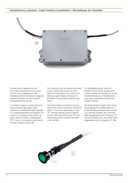
Il cliente che lo desidera riceverà<br />
una coppia <strong>di</strong> pulsanti luminosi ver<strong>di</strong><br />
(L) (con cavi <strong>di</strong> collegamento alla<br />
centralina dotati <strong>di</strong> connettore a sgancio<br />
rapido) da inserire nei fianchi esterni<br />
precedentemente lavorati.<br />
I connettori a sgancio rapido dovranno<br />
essere inseriti negli ingressi della<br />
centralina contrad<strong>di</strong>stinti dalla targhetta<br />
“P” e specificatamente nell’ingresso “P1”<br />
il cavo il cui puls<strong>ante</strong> verrà inserito nel<br />
fianco esterno sinistro e nell’ingresso<br />
“P2” il cavo il cui puls<strong>ante</strong> verrà inserito<br />
nel fianco esterno destro (M).<br />
The customer who so wishes will receive<br />
a pair of green light buttons (L) (with<br />
leads for connecting to the control unit<br />
featuring rapid-release connector) to<br />
be fitted in the previously worked outer<br />
sides.<br />
The rapid-release connectors must be<br />
fitted in the control unit inputs marked by<br />
plate “P” and more specifically in input<br />
“P1” the lead whose button is fitted in<br />
the left outer side and in input “P2” the<br />
lead whose button is fitted in the right<br />
outer side (M).<br />
Für <strong>di</strong>e Be<strong>di</strong>enung der Türen mit<br />
leichtem Druck auf <strong>di</strong>e Aussenk<strong>ante</strong><br />
(=Push) müssen <strong>di</strong>e Schalter (L) mit der<br />
Schnellverbindung zur Schaltbuchse<br />
in <strong>di</strong>e dazu vorbereitete Außenseiten<br />
montiert werden.<br />
Die Verbindungen müssen dann durch<br />
<strong>di</strong>e Eingänge mit der Beschriftung “P”<br />
an <strong>di</strong>e Schaltbuchseverbunden werden<br />
und zwar der Schalter der in <strong>di</strong>e linke<br />
Seite eingearbeitet wird in Eingang “P1”<br />
und der Schalter der in <strong>di</strong>e rechte Seite<br />
eingearbeitet wird in Eingang “P2” (M).<br />
L<br />
ø 16<br />
8<br />
Bortoluzzi Sistemi