IS. 2.5 50 Hz - Mase Generators of North America
IS. 2.5 50 Hz - Mase Generators of North America
IS. 2.5 50 Hz - Mase Generators of North America

You also want an ePaper? Increase the reach of your titles
YUMPU automatically turns print PDFs into web optimized ePapers that Google loves.
mase<br />
mase<br />
GENERATORS<br />
<strong>IS</strong>. <strong>2.5</strong><br />
<strong>50</strong> <strong>Hz</strong><br />
60 <strong>Hz</strong><br />
I<br />
GB<br />
MANUALE OFFICINA<br />
WORKSHOP MANUAL<br />
REV.0 A.A. 15-02-02 cod.42062
INDICE<br />
I<br />
Indice<br />
1 Identificazione della macchina .............. 5<br />
1.1 Composizione dei gruppi elettrogeni ........... 5<br />
2 TABELLA ATTREZZI .................................. 9<br />
3 ALTERNATORE ........................................ 13<br />
3.1 Statore ...................................................... 15<br />
3.1.1 Avvolgimenti di potenza ............................. 15<br />
3.1.2 Avvolgimenti di eccitazione ....................... 17<br />
3.1.3 Termostato alternatore .............................. 17<br />
3.1.4 Avvolgimenti di carica batteria ................... 19<br />
3.2 Rotore ....................................................... 21<br />
3.2.1 Avvolgimento di rotore (n°2) ...................... 21<br />
3.2.2 Diodi rotore (n°2) ....................................... 23<br />
3.2.3 Varistori rotore (n°2) .................................. 23<br />
3.3 Condensatori ............................................ 25<br />
4 MOTORE .................................................. 27<br />
4.1 Caratteristiche tecniche ............................ 25<br />
4.2 Manutenzione ........................................... 28<br />
4.3 Tavola guasti ............................................. 30<br />
4.4 Combustibile ............................................. 35<br />
4.5 Pompa gasolio elettrica ............................ 37<br />
4.6 Lubrificazione ............................................ 39<br />
5 SENSORI ................................................. 41<br />
5.1 Termostato testata motore aperto ............. 41<br />
5.2 Termostato motore a circuito chiuso (mare)43<br />
5.3 Pressostato olio........................................ 45<br />
6 RAFFREDDAMENTO ................................ 47<br />
6.1 Impianto “acqua mare/circuito chiuso" ...... 47<br />
6.2 Pompa acqua ........................................... 49<br />
6.3 Cinghia pompa acqua ............................... 51<br />
6.4 Scambiatore di calore acqua/aria.............. 53<br />
7 REGOLAZIONI ......................................... 55<br />
7.1 Regolazione dei giri .................................. 55<br />
7.2 Chiusura c<strong>of</strong>ano motore .......................... 57<br />
7.3 Pulizia filtro aria motore........................... 59<br />
7.4 Controllo livello olio ................................. 61<br />
7.5 Pulizia filtro olio motore ........................... 61<br />
8 IMPIANTO ELETTRICO ........................... 63<br />
8.1 Circuito di comando .................................. 63<br />
8.1.1 Cavo multipolare ....................................... 69<br />
8.2 Elettrovalvola ............................................. 71<br />
8.3 Interruttore termico (AC circuit breaker) .... 73<br />
8.4 Cablaggio motore ...................................... 75<br />
8.5 Caricabatteria ........................................... 77<br />
8.6 Fusibile ..................................................... 79<br />
8.7 Motorino avviamento ................................. 81<br />
8.8 Batteria ..................................................... 83<br />
9 SMONTAGGIO ......................................... 85<br />
9.1 Rimozione della cassa.............................. 85<br />
9.2 Rimozione alternatore ............................... 89<br />
9.3 Rimozione del coperchio alternatore lato ......<br />
cuscinetto ................................................. 91<br />
9.4 Rimozione dello statore ............................ 93<br />
9.5 Rimozione del rotore ................................. 95<br />
9.6 Rimozione del cuscinetto di rotore ............ 95<br />
2<br />
GB<br />
Index<br />
<strong>IS</strong> <strong>2.5</strong><br />
1 Machine identification........................5<br />
1.1 <strong>Generators</strong> composition .......................... 5<br />
2 TOOL TABLE .......................................... 9<br />
3 ALTERNATOR ..................................... 13<br />
3.1 Stator.................................................... 15<br />
3.1.1 Power windings..................................... 15<br />
3.1.2 Excitation windings ............................... 17<br />
3.1.3 Alternator thermostat ............................ 17<br />
3.1.4 Battery charger windings ................ 19<br />
3.2 Rotor ..................................................... 21<br />
3.2.1 Rotor winding (n°2) ............................... 21<br />
3.2.2 Rotor diodes (n°2) ................................. 23<br />
3.2.3 Rotor varistors (n°2) ............................ 23<br />
3.3 Capacitors ............................................ 25<br />
4 ENGINE ................................................ 27<br />
4.1 Technical features ................................. 25<br />
4.2 Maintenance ......................................... 28<br />
4.3 Trouble-shooting ................................... 30<br />
4.4 Fuel ...................................................... 35<br />
4.5 Electric diesel fuel pump ...................... 37<br />
4.6 Lubrication ............................................ 39<br />
5 SENSORS ............................................ 41<br />
5.1 Closed-circuit engine thermal switch .... 41<br />
5.2 Open-circuit engine thermostat (sea) .... 43<br />
5.3 Oil pressure switch ............................... 45<br />
6 SEA WATER COOLING ....................... 47<br />
6.1 Seawater/closed-circuit system ............ 47<br />
6.2 Water pump .......................................... 49<br />
6.3 Water pump belt ................................... 51<br />
6.4 Water/air heat exchanger...................... 53<br />
7 ADJUSTMENTS ................................... 55<br />
7.1 Rpm adjustment ................................... 55<br />
7.2 Closing cover motor............................. 57<br />
7.3 Engine air filter cleaning ...................... 59<br />
7.4 Level oil check ..................................... 61<br />
7.5 Engine oil filter cleaning ...................... 61<br />
8 ELECTRICAL SYSTEM ........................ 63<br />
8.1 Command circuit .................................. 63<br />
8.1.1 Multicore cable ..................................... 69<br />
8.2 Stop solenoid........................................ 71<br />
8.3 Thermal switch (AC circuit breaker) ........... 73<br />
8.4 Engine wiring ........................................ 75<br />
8.5 Battery charger ..................................... 77<br />
8.6 Fuse ..................................................... 79<br />
8.7 Starter motor ........................................ 81<br />
8.8 Battery .................................................. 83<br />
9 D<strong>IS</strong>ASSEMBLY .................................... 85<br />
9.1 Removing the casing............................. 85<br />
9.2 Removing the alternator ........................ 89<br />
9.3 Removing the alternator cover<br />
on the bearing side ............................... 91<br />
9.4 Removing the stator .............................. 93<br />
9.5 Removing the rotor ................................ 95<br />
9.6 Removing the rotor bearing ................... 95
<strong>IS</strong> <strong>2.5</strong><br />
I<br />
GB<br />
COPPIE DI SERRAGGIO VITI ................. 95<br />
RICAMBI .................................................. 96<br />
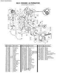
MOTORE-ALTERNATORE ...................... 96<br />
CASSA ..................................................... 98<br />
SCREW SHUT ..................................... 95<br />
SPARE PARTS .................................... 96<br />
ENGINE-ALTERNATOR...................... 96<br />
FRAME ................................................ 98<br />
INDEX<br />
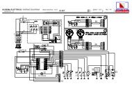
SCHEMA ELETTRICO .......................... 101<br />
WIRING DIAGRAM ............................... 101<br />
3
<strong>IS</strong> <strong>2.5</strong><br />
1 IDENTIFICAZIONE MACCHINA<br />
10<br />
SERIAL No.<br />
1<br />
2<br />
3<br />
4<br />
5<br />
6<br />
7<br />
8<br />
9<br />
2<br />
1<br />
3<br />
5<br />
6<br />
4<br />
7<br />
1<br />
4
<strong>IS</strong> <strong>2.5</strong><br />
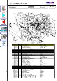
1 Identificazione della macchina<br />
(Fig.1)<br />
1 - Costruttore<br />
2 - Codice macchina<br />
3 - Anno di costruzione<br />
4 - Fattore di potenza<br />
5 - Frequenza dichiarata<br />
6 - Potenza continua<br />
7 - Tensione nominale<br />
8 - Corrente nominale<br />
9 - Peso<br />
10 - Numero di serie<br />
I dati che identificano il n ro di codice della macchina,<br />
il n ro di serie e l’anno di costruzione devono<br />
essere sempre precisati al Costruttore per informazioni,<br />
richieste di ricambi, ecc.<br />
1 Machine identification<br />
(Fig.1)<br />
1 - Manufacturer<br />
2 - Machine code<br />
3 - Year <strong>of</strong> construction<br />
4 - Power factor<br />
5 - Declared frequency<br />
6 - Continuous power<br />
7 - Rated voltage<br />
8 - Rated current<br />
9 - Weight<br />
10 - Serial number<br />
The machine code number, the serial number<br />
and the year <strong>of</strong> construction must always be<br />
quoted when contacting the manufacturer for<br />
information, requests for spare parts, etc.<br />
1 MACHINE IDENTIFICATION<br />
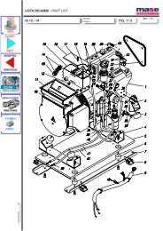
1.1 Composizione dei gruppi elettrogeni<br />
1.1 <strong>Generators</strong> composition<br />
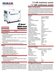
I gruppi elettrogeni sono composti essenzialmente<br />
dai seguenti componenti (Fig.1-2):<br />
1 - Cassa insonorizzante<br />
2 - Portello di accesso superiore<br />
3 - Portello di accesso lato motore<br />
4 - Staffe di ancoraggio<br />
5 - Raccordo scarico fumi e acqua di raffreddamento<br />
6 - Raccordo collegamento presa acqua mare<br />
7 - Raccordi di collegamento a serbatoio carburante<br />
The generators are essentially composed <strong>of</strong><br />
the following components (Fig.1-2):<br />
1- Soundpro<strong>of</strong> casing<br />
2- Top access door<br />
3- Motor side access door<br />
4- Anchoring brackets<br />
5- Exhaust and cooling water pipe fitting<br />
6- Seawater intake connection pipe fitting<br />
7- Connection pipe fittings to fuel tank<br />
5
<strong>IS</strong> <strong>2.5</strong><br />
18<br />
19<br />
12<br />
1 IDENTIFICAZIONE MACCHINA<br />
21<br />
16<br />
14 13<br />
9<br />
11<br />
10<br />
15<br />
8A<br />
8B<br />
17<br />
23<br />
22<br />
20<br />
2<br />
6
<strong>IS</strong> <strong>2.5</strong><br />
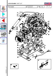
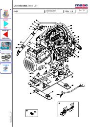
8A- Collegamento batteria +<br />
8B- Collegamento batteria -<br />
9 - Vite di regolazione giri del motore<br />
10- Filtro aria motore<br />
11- Asta livello olio<br />
12- Pompa acqua mare<br />
13- Pompa carburante<br />
14- Cartuccia filtro olio<br />
15- Tappo carico olio<br />
16- Scatola collegamento linea elettrica<br />
17- Regolatore caricabatteria<br />
18- Scambiatore di calore acqua/aria<br />
19- Collettore scarico<br />
20- Motorino di avviamento<br />
21 - Connettore pannello di comando a distanza<br />
22- Condensatore<br />
23- Fusibile<br />
8A- Connection to battery +<br />
8B-Connection to battery -<br />
9- RPM adjusting screw <strong>of</strong> engine<br />
10- Engine air filter<br />
11- Staff oil level<br />
12- Seawater pump<br />
13- Fuel pump<br />
14- Oil filter cartridge<br />
15- Oil fillercap<br />
16- Electric line connection box<br />
17- Battery charger regolator<br />
18- Water/air heat exchanger<br />
19- Exhaust manifold<br />
20- Starter motor<br />
21- Remote control panel connector<br />
22- Capacitor<br />
23- Fuse<br />
1 MACHINE IDENTIFICATION<br />
7
<strong>IS</strong> <strong>2.5</strong><br />
2 TABELLA ATTREZZI<br />
3<br />
8
<strong>IS</strong> <strong>2.5</strong><br />
2 Tabella attrezzi<br />
Denominazione : Chiave torsiometrica<br />
Uso : Serve per serrare bulloni e dadi alla<br />
coppia prescritta<br />
Denominazione : Tester batteria<br />
2 TOOL TABLE<br />
Denomination: Torque spanner<br />
Use: To tighten the nuts and bolts to the<br />
prescribed torque<br />
Denomination: Battery tester<br />
2 TOOL TABLE<br />
Uso : Controlla lo stato di carica dell’elettrolito<br />
della batteria<br />
Use: To check the electrolyte level <strong>of</strong> the battery<br />
Denominazione : Termometro digitale<br />
Uso : Misura la temperatura dei componenti<br />
Denomination: Digital thermometer<br />
Use: Measures the temperature <strong>of</strong> the<br />
components<br />
Denominazione : Tachimetro a contatto<br />
Uso : Misura i giri/min. dell’albero rotante<br />
portando la testa dell’indicatore a contatto del<br />
foro centrale dell’albero.<br />
Denomination: Contact tachometer<br />
Use: Measures the rpm <strong>of</strong> the rotary shaft by<br />
bringing the indicator tip in contact with the<br />
central hole <strong>of</strong> the shaft.<br />
Denominazione : Tachimetro a fotocellula<br />
Uso : Permette di rilevare i giri dell’albero rotante<br />
quando questo si trova in posizione scomode,<br />
tenendo il tachimetro ad una certa distanza.<br />
Denomination: Photocell tachometer<br />
Use: Allows measuring the rpm <strong>of</strong> the rotary<br />
shaft when it is in uncomfortable positions,<br />
holding the tachometer at a certain distance.<br />
Denominazione : Tachimetro a morsetto per<br />
tubo combustibile ad alta pressione<br />
Uso : Misura i giri/min. del motore usando un<br />
sistema ad impulsi, senza tener conto del centro<br />
dell’albero rotante e della circonferenza<br />
dell’oggetto rotante<br />
Denomination: Terminal tachometer for highpressure<br />
fuel pipe<br />
Use: Measures the engine rpm using a pulse<br />
system not taking into account the centre <strong>of</strong> the<br />
rotary shaft and the circumference <strong>of</strong> the rotating<br />
object.<br />
9
<strong>IS</strong> <strong>2.5</strong><br />
2 TABELLA ATTREZZI<br />
4<br />
10
<strong>IS</strong> <strong>2.5</strong><br />
Denominazione : Tester<br />
Uso : Misura la tensione AC/DC , le resistenze<br />
ed i diodi<br />
Denominazione : Pinza amperometrica<br />
Uso : Misura la tensione AC, frequenza (n° di<br />
giri motore) e corrente AC.<br />
Si può quindi risalire alla potenza che stiamo<br />
prelevando dal generatore.<br />
Denomination: Tester<br />
Use: Measures the AC/DC voltage, the resistors<br />
and the diodes<br />
Denomination: Amperometric caliper<br />
Use: Measures the AC voltage, frequency<br />
(engine rpm) and AC current.<br />
The power drawn from the generator can thus<br />
be measured.<br />
2 TOOL TABLE<br />
Denominazione : Amperometro<br />
Uso : Misura la corrente di linea collegandolo in<br />
serie<br />
Denomination:Ammeter<br />
Use: Measures the line current connecting it in<br />
series<br />
Denominazione : Frequenzimetro<br />
Uso : Misura la frequenza (n° di giri motore)<br />
collegandolo in parallelo alla linea 230-115V del<br />
generatore<br />
Denomination:Frequency meter<br />
Use: Measures the frequency (engine rpm)<br />
connecting it in parallel to the 230-115V line <strong>of</strong><br />
the generator.<br />
Denominazione : Estrattore<br />
Uso : Utilizzato per l'estrazione del coperchio<br />
cuscinetto alternatore, e del cuscinetto di rotore<br />
Denomination: Extractor<br />
Use: Used to extract the alternator bearing<br />
cover and the rotor bearing.<br />
11
<strong>IS</strong> <strong>2.5</strong><br />
3 ALTERNATORE<br />
5<br />
12
<strong>IS</strong> <strong>2.5</strong><br />
3 ALTERNATORE<br />
I generatori della serie <strong>IS</strong> <strong>2.5</strong>, sono dotati di alternatore<br />
senza spazzole, sincrono, a 2 poli,<br />
autoregolato, autoeccitato, con 1 condensatore<br />
(fig. 2 rif. 22) collegato all'avvolgimento ausiliario<br />
di eccitazione statore. L’alternatore genera una<br />
tensione alternata, disponibile ai morsetti a una<br />
frequenza di <strong>50</strong>/60 <strong>Hz</strong>. (Corrispondenti alla velocità<br />
del motore primo di 3000/3600 rpm) secondo il<br />
principio di seguito descritto.<br />
All’avviamento il magnetismo di rotore (magnetismo<br />
residuo del nucleo) induce negli avvolgimenti<br />
ausiliari di eccitazione una tensione.<br />
Questa tensione è applicata al condensatore, e fa<br />
circolare nel circuito chiuso, costituito dal<br />
condensatore e dall’avvolgimento ausiliario, una<br />
corrente capacitiva.<br />
Questa corrente produce un campo magnetico<br />
che rafforza il magnetismo di rotore, generando in<br />
esso una tensione che, raddrizzata dai diodi, fa<br />
circolare una corrente continua negli avvolgimenti<br />
induttori di rotore.<br />
Il campo magnetico rotante dovuto alla circolazione<br />
di questa corrente genera a sua volta<br />
nell’avvolgimento principale la tensione nominale<br />
ai morsetti del generatore.<br />
3 ALTERNATOR<br />
The generators <strong>of</strong> the <strong>IS</strong> <strong>2.5</strong>, series are equipped<br />
with a brushless, synchronous, 2-pole, selfregulating,<br />
self-excited alternator with 1 capacitor<br />
(Fig. 2 Ref. 22) connected to the auxiliary winding<br />
for stator excitation. The alternator generates<br />
alternate voltage available at the terminals at a<br />
frequency <strong>of</strong> <strong>50</strong>/60 <strong>Hz</strong> (corresponding to the speed<br />
<strong>of</strong> the prime mover <strong>of</strong> 3000/3600 rpm) according to<br />
the principle described below.<br />
Upon starting, the rotor magnetism (residual<br />
magnetism <strong>of</strong> the nucleus) induces a voltage in the<br />
auxiliary excitation windings.<br />
This voltage is applied to the capacitor, and makes<br />
a capacitive current circulate in the closed circuit<br />
composed <strong>of</strong> the capacitor and the auxiliary winding.<br />
This current produces a magnetic field which<br />
strengthens the rotor magnetism generating a<br />
voltage inside it which, rectified by the diodes,<br />
makes a continuous current circulate in the rotor<br />
field windings.<br />
The rotating magnetic field due to circulation <strong>of</strong> this<br />
current in its turn generates in the primary winding<br />
the rated voltage to the generator terminals.<br />
3 ALTERNATOR<br />
CONTROLLI<br />
Tutte le misure di resistenza si intendono eseguite<br />
ad alternatore freddo, temperatura ambiente 10 -<br />
30 °C e con strumentazione tale da permettere la<br />
lettura dei valori indicati.<br />
La tolleranza rispetto ai valori riportati è<br />
indicativamente ± 10%.<br />
Letture approssimative, eseguite con strumenti di<br />
portata non adeguata, possono unicamente<br />
indicare la continuità dell’avvolgimento ma non<br />
danno indicazioni su eventuali corto circuiti.<br />
N.B.<br />
Oltre alle possibilità di guasto che sono indicate<br />
in seguito si può presentare il caso di uno o più<br />
avvolgimenti a massa. Si consiglia quindi di<br />
controllare queste eventualità verificando con<br />
un tester che non ci sia continuità fra i vari<br />
avvolgimenti (identificati nei paragrafi<br />
successivi) verso massa e fra gli stessi.<br />
TESTS<br />
All the resistance measurements are made with<br />
the alternator cold, ambient temperature 10 - 30<br />
°C, and with instrumentation such as to allow<br />
reading the values indicated.<br />
The tolerance with respect to the values listed is<br />
approximately ± 10%.<br />
Approximate readings made with instruments with<br />
inadequate range, can only indicate continuity <strong>of</strong><br />
the winding but do not give an indication <strong>of</strong> any<br />
short-circuits.<br />
N.B.<br />
Apart from the failure possibilities indicated below,<br />
there might be one or more earth windings. It is<br />
therefore recommended to test these possibilities,<br />
checking with a tester that there is no continuity<br />
between the various windings (identified in the<br />
following paragraphs) to earth and between them.<br />
13
<strong>IS</strong> <strong>2.5</strong><br />
3 ALTERNATORE<br />
1<br />
5<br />
1<br />
3 3<br />
4 4<br />
2 0<br />
20 4<br />
2<br />
10<br />
<strong>50</strong>(60)<br />
1<br />
1<br />
3<br />
4<br />
1<br />
2<br />
3<br />
6<br />
14
<strong>IS</strong> <strong>2.5</strong><br />
3.1 Statore (Fig.6, rif5)<br />
3.1.1 Avvolgimenti di potenza (Fig.6, rif.1)<br />
Caratteristiche:<br />
3.1 Stator (Fig.6, ref5)<br />
3.1.1 Power windings (Fig.6, ref.1)<br />
Features:<br />
3 ALTERNATOR<br />
Metodo di controllo:<br />
- Assicurarsi che il termico di bordo sia armato.<br />
- Scollegare dalla morsettiera i cavi di potenza<br />
contrassegnati dalle lettere P 1<br />
F 1<br />
P 2<br />
F 2<br />
-Verificare che la resistenza fra le estremità di<br />
entrambe le coppie di cavi P 1<br />
F 1<br />
e P 2<br />
F 2<br />
rientri<br />
nei valori indicati in tabella.<br />
N.B. La resistenza totale dell'avvolgimento (nel<br />
collegamento 220 V o 240 V) si misura<br />
ponticellando F 1<br />
e P 2<br />
. La misura effettuata fra i<br />
punti P 1<br />
e F 2<br />
sarà il doppio del valore indicato in<br />
tabella.<br />
RIMEDIO: Sostituire lo statore<br />
ATTENZIONE: Gli avvolgimenti sono trattati<br />
con resine e vernici per ambienti con clima<br />
umido-salino. Se tali trattamenti sono<br />
deteriorati, sostituire !<br />
Test method:<br />
- Ensure that the onboard thermal switch is armoured<br />
- Disconnect from the terminal board, the wires<br />
coming from the stator, marked by the letters P 1<br />
F 1<br />
P 2<br />
F 2<br />
.<br />
- Verify that the resistance values between the two<br />
pairs <strong>of</strong> wire terminals P 1<br />
F 1<br />
and P 2<br />
F 2<br />
are within the<br />
limits as reported in the table above.<br />
N.B. The total resistance value for power winding<br />
(220 V 240 V) is measured connecting F 1<br />
and P 2<br />
.<br />
the resistance value measured between P 1<br />
and F 2<br />
is double <strong>of</strong> that indicated in the table above.<br />
REMEDY: Replace the stator<br />
WARNING: The windings have been treated<br />
with resin and paint for humid-saline climates. If<br />
these treatments have deteriorated, replace !<br />
15
<strong>IS</strong> <strong>2.5</strong><br />
3 ALTERNATORE<br />
2<br />
1<br />
7<br />
8<br />
16
<strong>IS</strong> <strong>2.5</strong><br />
I<br />
GB<br />
3.1.2 Avvolgimenti di eccitazione (Fig.6, rif.2)<br />
Caratteristiche:<br />
3.1.2 Excitation windings (Fig.6, ref.2)<br />
Features:<br />
<strong>50</strong><strong>Hz</strong><br />
60<strong>Hz</strong><br />
n° Colore colore / Color <strong>IS</strong> 3,5 n° Colore colore / Color <strong>IS</strong> 4,0<br />
ECCITAZIONE / 0 Rosso-Red 0 Rosso-Red<br />
ECCITAZIONE 2,52 2,76<br />
EXCITATION <strong>50</strong> Nero-black 60 Bianco-White<br />
2,08 2,29<br />
3 ALTERNATOR<br />
Metodo di controllo<br />
- Togliere il cappuccio di protezione.<br />
- Scollegare il condensatore (Fig. 7 rif.1) dai<br />
cavi provenienti dallo statore (Fig. 7 rif.2).<br />
- Verificare che la resistenza fra le estremità dei<br />
cavi rientri nei valori indicati in tabella.<br />
RIMEDIO: Sostituire lo statore.<br />
Test method<br />
- Remove the protective cap.<br />
- Disconnect the cables (Fig. 7 Ref.1) coming<br />
from the stator from the capacitor (Fig. 7 Ref.2).<br />
- Check that the resistance between the ends <strong>of</strong><br />
the cables falls within the values indicated in the<br />
table.<br />
REMEDY: Replace the stator.<br />
3.1.3 Termostato Alternatore (Fig.6, rif.4)<br />
Caratteristiche: Normalmente chiuso.<br />
Temperatura d’intervento 180° C.<br />
Metodo di controllo:<br />
-Accedere alla zona morsettiera allacciamento<br />
potenza (Fig. 8).<br />
-Scollegare i fili rossi (o bianchi) da 1.0mm 2 da<br />
morsetti 17 e 18.<br />
-Verificare la continuità fra le due estremità dei<br />
cavi.<br />
RIMEDIO: Sostituire lo statore<br />
N.B.: Il termostato alternatore, può intervenire per<br />
sovraccarico o per sovratemperatura.<br />
Verificare quindi, se è necessario, i carichi applicati<br />
e la temperatura d’esercizio del generatore, con<br />
particolare attenzione alla sua installazione.<br />
3.1.3 Alternator thermostat (Fig.6, ref.4)<br />
Characteristics: Normally closed.<br />
Operating temperature: 180° C.<br />
Test method:<br />
-Access the power connection terminal board<br />
area (Fig. 8).<br />
-Disconnect the 1.0 mm 2 red (or white) wires<br />
from the 17 and 18 terminal board.<br />
-Check continuity between the two ends <strong>of</strong> the<br />
cables.<br />
REMEDY: Replace the stator<br />
N.B.: The alternator thermostat may intervene<br />
because <strong>of</strong> an overload or overtemperature.<br />
Therefore, check if necessary, the applied loads<br />
and the operating temperature <strong>of</strong> the generator<br />
with particular attention to its installation.<br />
17
<strong>IS</strong> <strong>2.5</strong><br />
2<br />
1<br />
9<br />
18
<strong>IS</strong> <strong>2.5</strong><br />
3.1.4 Avvolgimenti di carica batteria<br />
(Fig.6, rif.3)<br />
Caratteristiche:<br />
3.1.4 Battery charger windings<br />
(Fig.6, Ref.3)<br />
Characteristics:<br />
CARICA<br />
BATTERIA<br />
<strong>50</strong><strong>Hz</strong><br />
60<strong>Hz</strong><br />
n° colore <strong>IS</strong> 3,5 n° colore <strong>IS</strong> 4,0<br />
5 Blù-Blue 6 Verde-Green<br />
0,162 0,13<br />
5 Blù-Blue 6 Verde-Green<br />
0,127 0,11<br />
Metodo di controllo<br />
- Scollegare la batteria dal gruppo.<br />
- Scollegate i 2 cavi dal regolatore<br />
contrassegnati 5 o 6 (Fig. 9 rif.1) (sul<br />
regolatore, corrispondono i simboli "~" "~") e<br />
verificare che la resistenza rientri nei valori<br />
indicati in tabella.<br />
- Verificare che la resistenza fra ciascun cavo<br />
ed il filo nero (sez.<strong>2.5</strong>mm 2 contrassegnato +<br />
Fig. 9 rif.2), sia la metà del valore indicato in<br />
tabella<br />
Test method<br />
- Disconnect the battery from the generator.<br />
- Disconnect the 2 cables marked 5 or 6 (Fig. 9<br />
Ref.1) from the regulator (the corresponding<br />
symbols “~” “~” on the regulator) and check that<br />
the resistance falls within the values indicated in<br />
the table.<br />
- Check that the resistance between each cable<br />
and the black wire (<strong>2.5</strong> mm 2 cross-section<br />
marked + Fig. 9 Ref.2 ) is half the value<br />
indicated in the table.<br />
19
<strong>IS</strong> <strong>2.5</strong><br />
3 ALTERNATORE<br />
1<br />
10<br />
20
<strong>IS</strong> <strong>2.5</strong><br />
3.2 Rotore<br />
3.2 Rotor<br />
3.2.1 Avvolgimento di rotore (n°2)<br />
Caratteristiche:<br />
3.2.1 Rotor winding (n°2)<br />
Features:<br />
<strong>IS</strong> 3,5 2,5 4,0<br />
<strong>50</strong> / 60HZ<br />
Rotore- Rotor<br />
2,11 2,37<br />
Condensatore - Capacitor 25micrF<br />
3 ALTERNATOR<br />
Metodo di controllo:<br />
-Verificare che la resistenza fra le due<br />
estremità dei diodi rientri nei valori indicati.<br />
(Fig. 10).<br />
RIMEDIO: Sostituire il rotore<br />
IMPORTANTE<br />
La mancanza di tensione in uscita può essere<br />
causata eccezionalmente dalla mancanza o<br />
insufficienza di magnetismo residuo del rotore.<br />
Come primo intervento si consiglia, con il<br />
generatore in moto, di collegare per un attimo una<br />
batteria 12 V ai terminali del condensatore o,<br />
all’uscita di potenza.<br />
In questo modo il rotore viene istantaneamente<br />
magnetizzato.<br />
Test method:<br />
-Check that the resistance between the two<br />
ends <strong>of</strong> the diodes falls within the values<br />
indicated. (Fig.10).<br />
REMEDY: Replace the rotor<br />
IMPORTANT<br />
Failed output voltage may exceptionally be caused<br />
by absence or insufficiency <strong>of</strong> residual rotor<br />
magnetism.<br />
As first operation, it is recommended, with the<br />
generator running, to briefly connect a 12V battery<br />
to the capacitor terminals or to the power output.<br />
That way the rotor is instantaneously magnetised.<br />
21
A<br />
<strong>IS</strong> <strong>2.5</strong><br />
3 ALTERNATORE<br />
A<br />
K<br />
K<br />
A<br />
K<br />
11<br />
22
<strong>IS</strong> <strong>2.5</strong><br />
3.2.2 Diodi rotore (n°2)<br />
Caratteristiche : SKR 26/16<br />
Metodo di controllo:<br />
-Scollegate i cavi all’estremità A dei 2 diodi<br />
(Fig. 11)<br />
-Verificate con un tester con il puntale + su A e<br />
– su K ci sia continuità.<br />
-Verificate che invertendo i puntali del tester<br />
non ci sia continuità.<br />
RIMEDIO: Sostituire il diodo difettoso.<br />
3.2.2 Rotor diodes (n°2)<br />
Characteristics : SKR 26/16<br />
Test method:<br />
-Disconnect the cables at end A <strong>of</strong> the 2 diodes<br />
(Fig. 11)<br />
-Check with a tester with the + prod on A and the<br />
- prod on K if there is continuity.<br />
-Check that when inverting the tester prods there<br />
is no continuity.<br />
REMEDY: Replace the faulty diode.<br />
3 ALTERNATOR<br />
3.2.3 Varistori rotore (n°2)<br />
Caratteristiche : V420 K10<br />
Metodo di controllo:<br />
- Scollegare i re<strong>of</strong>ori di ciascun varistore dagli<br />
avvolgimenti rotore<br />
- Verificare che non presenti segni di bruciatura<br />
- Controllare con un tester, che non ci sia<br />
continuità.<br />
RIMEDIO: Sostituire entrambi i varistori.<br />
3.2.3 Rotor varistors (n. 2)<br />
Characteristics : V420 K10<br />
Test method:<br />
- Disconnect the rheophores <strong>of</strong> each varistor<br />
from the rotor windings.<br />
- Check that there are no burn marks.<br />
- With a tester check that there is no<br />
continuity.<br />
REMEDY: Replace both varistors.<br />
23
<strong>IS</strong> <strong>2.5</strong><br />
3 ALTERNATORE<br />
12<br />
24
<strong>IS</strong> <strong>2.5</strong><br />
3.3 Condensatore<br />
Caratteristiche – 25 uF 4<strong>50</strong>V <strong>50</strong> <strong>Hz</strong>:<br />
Metodo di controllo:<br />
-Scollegate i cavi dal condensatore.<br />
-Verificate che la resistenza ai loro estremi non<br />
sia inferiore a 200K Ohm.<br />
N.B.: Con questa prova si verifica che il<br />
condensatore non sia in cortocircuito.<br />
Una diminuzione di capacità, ha come effetto una<br />
diminuzione della tensione a vuoto, è difficilmente<br />
valutabile.<br />
In questo caso, verificate altre possibili cause, si<br />
consiglia di sostituire il condensatore.<br />
RIMEDIO: Sostituire il condensatore<br />
3.3 Capacitor<br />
Characteristics - 25 uF 4<strong>50</strong>V <strong>50</strong> <strong>Hz</strong>:<br />
Test method:<br />
-Disconnect the cables from the capacitor.<br />
-Check that the resistance at their ends is not<br />
less than 200K Ohm.<br />
N.B.: This test is done to check that the capacitor<br />
is not in short-circuit.<br />
Reduced capacitance results in reduced no-load<br />
voltage and is difficult to evaluate.<br />
In this case, check for other possible causes. It is<br />
recommended to replace the capacitor.<br />
REMEDY: Replace the capacitor<br />
3 ALTERNATOR<br />
25
<strong>IS</strong> <strong>2.5</strong><br />
4 MOTORE<br />
13<br />
26
<strong>IS</strong> <strong>2.5</strong><br />
4 Motore 4 Engine<br />
4.1 Caratteristiche tecniche<br />
Unità<br />
Modello<br />
L 40 70 AE<br />
Tipo<br />
- Motore diesel a 4 tempi, verticale, raffreddato ad aria<br />
Sistema di combustione<br />
-<br />
Diretta<br />
N° cilindri - Alesaggio x Corsa<br />
mm<br />
1\78X62 1/70x55<br />
Materiale blocco cilindri<br />
Alluminio<br />
Cilindrata<br />
c.c<br />
296<br />
Velocità di rotazione<br />
giri/min. 3000 3600<br />
Potenza*<br />
Potenza continuativa PS<br />
Potenza massima PS 4,2 6.1 4,7 6.7<br />
Senso di rotazione<br />
-<br />
Antiorario (vista volano)<br />
Rapporto di compressione<br />
-<br />
19.5 20:1<br />
Combustibile diesel consigliato<br />
- <strong>IS</strong>O 8217 DMA, BS 2869 A1 o A2 (Cetano N.:45 min.)<br />
Sistema di lubrificazione<br />
-<br />
Lubrificazione forzata con pompa trocoide<br />
Capacità serbatoio olio lubrificante<br />
Max/effettiva<br />
lt<br />
1,1<br />
Olio lubrificante consigliato<br />
-<br />
Qualità API calsse CC o superiore<br />
Regolatore<br />
-<br />
Regolatore meccanico centrifugo (tutte le velocità)<br />
Sistema d'accensione<br />
-<br />
Elettrico<br />
Sistema di arresto motore<br />
-<br />
Elettrovalvola / 12V<br />
Pompa alimentazione carburante<br />
-<br />
Elettrica / 12V<br />
Prevalenza max.pompa carburante<br />
cm.<br />
70<br />
Consumo carburante a pieno carico (l/h) 0,7 1.3 0,8 1.5<br />
Volume aria combustione<br />
(l/min) 280 400 340 480<br />
Inclinazione max.di utilizzo gradi<br />
30<br />
4 ENGINE<br />
4.1 Technical features<br />
Unit<br />
Model<br />
L 40 70 AE<br />
Type<br />
-<br />
4-stroke, vertical, air-cooled diesel engine<br />
direct<br />
No. <strong>of</strong> cylinders - Bore x Stroke mm<br />
1\78X62 1/70x55<br />
Cylinder block material<br />
Alluminium<br />
Displacement c.c<br />
296<br />
Rotation speed<br />
Rpm 3000 3600<br />
Continuous power PS<br />
Power*<br />
Maximum power PS 4,2 6.1 4,7 6.7<br />
Direction <strong>of</strong> rotation<br />
-<br />
Anticlockwise (flywheel view)<br />
Compression ratio<br />
-<br />
20:1<br />
Recommended diesel fuel - <strong>IS</strong>O 8217 DMA, BS 2869 A1 or A2 (Cetane number: min. 45)<br />
Lubrication system<br />
-<br />
Forced lubrication with trochoid pump<br />
Engine oil tank capacity<br />
Max/effective lt 1.1<br />
Recommended engine oil<br />
-<br />
API quality, Class CC or higher<br />
Regulator<br />
-<br />
Mechanical centrifuge regulator (all speeds)<br />
Ignition system<br />
-<br />
Electric<br />
Engine stopping system<br />
-<br />
Solenoid / 12V<br />
Fuel pump<br />
-<br />
Electric / 12V<br />
Max. head fuel pump<br />
cm.<br />
70<br />
Fuel consumption at full power (l/h) 0,7 1.3 0,8 1.5<br />
Combustion air volume<br />
(l/min) 280 400 340 480<br />
Max. operating inclination degrees<br />
30<br />
27
<strong>IS</strong> <strong>2.5</strong><br />
4 MOTORE<br />
4.2 Manutenzione<br />
Per la durata e il corretto funzionamento del generatore è necessario rispettare il programma di<br />
controlli e manutenzione indicati nella tabella seguente.<br />
L’esecuzione di queste operazioni è descritta, per la parte relativa al motore, sul libretto uso e<br />
manutenzione o sul manuale d’<strong>of</strong>ficina del costruttore del motore.<br />
Si ricorda inoltre che durante le normali operazioni di manutenzione (Montaggio/smontaggio) è<br />
necessario rispettare alcune regole generali, quindi:<br />
- rispettare le coppie di serraggio.<br />
- utilizzare grassi, olii, frenafiletti appropriati.<br />
- non lavare avvolgimenti o parti elettriche con acidi o sostanze corrosive.<br />
- spruzzare disossidanti sui contatti elettrici<br />
- rispettare la numerazione dei cavi.<br />
Se necessario annotarne la numerazione e la posizione.<br />
OPERAZIONE .....................................................................ORE<br />
Controllo livello olio motore ................................................ 10<br />
Controllare che non vi siano perdite di olio ...................... 20<br />
Controllare che non vi siano perdite di carbur. ................ 20<br />
Regolazione tensione cinghia trapezoidale .................... 100<br />
Verifica carica batteria ........................................................ 100<br />
Pulire filtro combustibile .................................................... 200<br />
* Cambio olio motore .......................................................... 200<br />
Controllare la girante pompa acqua mare ........................ 400<br />
Controllare il numero di giri motore ................................. 400<br />
Controllare l’integrità dei collegamenti elettr. ................ 400<br />
Sostituzione filtro combustibile......................................... 400<br />
* Sostituzione filtro olio ...................................................... 400<br />
Controllare iniettore ........................................................... 400<br />
Controllare la fasatura iniezione ....................................... 400<br />
Regolazione gioco valvola presa/scarico ........................ 400<br />
Controllare la pompa di iniezione combustib. .............. 1.000<br />
Controllo livello elettrolita batteria.............................. mens.<br />
Pulire e disossidare le parti metalliche ......................... anno<br />
Pulizia filtro aria................................................................ anno<br />
Sostituzione anodi di zinco ............................................ anno<br />
* Eseguire il primo intervento dopo <strong>50</strong> ore i successivi secondo gli intervalli previsti.<br />
Ciclo di vita motore<br />
ore<br />
Tempo medio intercorrente tra un guasto e l'altro <strong>50</strong>0<br />
*Prima revisione parziale 700<br />
*Revisione totale 2000<br />
*sbarcare il gruppo<br />
I<br />
28
<strong>IS</strong> <strong>2.5</strong><br />
4.2 Maintenance<br />
GB<br />
For long life and proper functioning <strong>of</strong> the generator, the checking and maintenance schedule indicated<br />
in the following table must be respected.<br />
How to execute these operations is described, for the part relating to the engine, in the use and<br />
maintenance handbook or in the workshop manual <strong>of</strong> the engine manufacturer.<br />
During normal maintenance operations (assembly/disassembly) some general rules must be followed<br />
- respect the tightening torques.<br />
- use suitable grease, oils, and thread-locking fluid.<br />
- do not wash the windings or electrical parts with acid or corrosive substances.<br />
- spray deoxidiser on the electrical contacts<br />
- respect the cable numbering.<br />
If necessary note down the numbering and the position.<br />
OPERATION ................................................................. HOURS<br />
Engine oil level check ..........................................................10<br />
Check that there are no oil leaks ........................................20<br />
Check that there are no fuel leaks ......................................20<br />
V-belt tension adjustment ..................................................100<br />
Battery charger check ........................................................100<br />
Clean the fuel filter .............................................................200<br />
* Engine oil change .............................................................200<br />
Check the seawater pump rotor ........................................400<br />
Check the engine rpm ........................................................400<br />
Check integrity <strong>of</strong> the electrical connections. .................400<br />
Fuel filter replacement .......................................................400<br />
* Oil filter replacement........................................................400<br />
Check the injector ..............................................................400<br />
Check the injecting timing .................................................400<br />
Intake/exhaust valve play adjustment ..............................400<br />
Check the fuel injection pump ........................................1.000<br />
Battery electrolyte level check .................................. monthly<br />
Clean and deoxidise the metallic parts ....................... yearly<br />
Air filter cleaning ............................................................ yearly<br />
Zinc anode replacement ............................................... yearly<br />
* Carry out the first operation after <strong>50</strong> hours, subsequently according to the fixed intervals.<br />
Engine life cycle<br />
Hours<br />
Average time elapsing between one fault and the next <strong>50</strong>0<br />
*First partial overhaul 700<br />
*Total overhaul 2000<br />
*unship the generator<br />
4 ENGINE<br />
29
<strong>IS</strong> <strong>2.5</strong><br />
4.3 Tavola guasti<br />
I<br />
PROBLEMI DI<br />
AVVIAMENTO<br />
TABELLA GUASTI MOTORE<br />
POTENZA MOTORE<br />
INSUFFICENTE<br />
ERRONEO<br />
COLORE DEI GAS<br />
DI SCARICO<br />
OSCILLAZIONI,<br />
INSTABILITA'<br />
OLIO LUBRIFICANTE<br />
LIQUIDO<br />
REFRIGERANT<br />
E<br />
CAUSA<br />
GUASTO<br />
4 MOTORE<br />
NULLA<br />
POCO<br />
MOLTO<br />
AL MINIMO<br />
CONSUMO ECCESSIVO<br />
MESCOLATO COL GASOLIO<br />
MESCOLATO CON ACQUA<br />
IL MOTORE SI AVVIA<br />
MA SI FERMA SUBITO<br />
FUMO ALLO<br />
SCARICO<br />
COLORE DEI GAS DI<br />
SCARICO<br />
IN FUNZIONE<br />
IN FUNZIONE<br />
GIOCO INADEGUATO DELLA VALVOLA DI ASPIRAZIONE • • •<br />
PERDITA DI COMPRESSIONE DELLA SEDE DELLA VALVOLA • • • • •<br />
VALVOLA ASPIRAZIONE/SCARICO GRIPPATA • • • • •<br />
GUARNIZIONE DELLA TESTA CILINDRO DANNEGGIATA • • •<br />
FASCIA ELASTICA DEL P<strong>IS</strong>TONE GRIPPATA O ROTTA • • • • • • •<br />
FASCIA ELASTICA DEL P<strong>IS</strong>TONE E CILINDRO USURATI • • • • • •<br />
GUIDA VALVOLA ASPIRAZIONE/SCARICO USURATA • •<br />
REGOLATORE POMPA INIEZIONE DETERIORATO • •<br />
EFFETTO RAFFREDDANTE RIDOTTO DELLO SCAMBIATORE • •<br />
TENSIONE ERRATA DELLA CINGHIA E DELLA POMPA • •<br />
CARATTER<strong>IS</strong>TICHE ERRATE DELL'OLIO LUBRIFICAZIONE • • • •<br />
PERDITE DAI TUBI DELL'OLIO LUBRIFICANTE •<br />
FILTRO OLIO LUBRIFICANTE INTASATO<br />
VALVOLA CONTROLLO PRESSIONE DETERIORATA<br />
GASOLIO CON CARATTER<strong>IS</strong>TICHE ERRATE • • • • •<br />
ACQUA ALL'INTERNO DELL'IMPIANTO D'ALIMENTAZIONE • • • • •<br />
FILTRO COMBUSTIBILE / POMPA ELETTRICA INTASATI • • •<br />
ARIA ALL'INTERNO DELL'IMPIANTO DI ALIMENTAZIONE • • •<br />
TUBO ALIMENTAZIONE COMBUSTIBILE ROTTO OD USTRUITO • • •<br />
ALIMENTAZIONE INSUFFICENTE ALLA POMPA D'INIEZIONE • • •<br />
MANDATA DELLA POMPA D'INIEZIONE IRREGOLARE • • • •<br />
GETTO INSUFFICENTE DEL POLVERIZZATORE • • • •<br />
FILTRO ARIA INTASATO • • •<br />
TUBO DI SCARICO OSTRUITO • •<br />
RIMEDI<br />
• • REG<strong>IS</strong>TRARE IL GIOCO DELLE VALVOLE<br />
• • LAPPATURA DELLA SEDE DELLA VALVOLA<br />
• SOSTITUIRE<br />
• SOSTITUIRE LA GUARNIZIONE<br />
• • SOSTITUIRE LA FASCIA ELASTICA DEL P<strong>IS</strong>TONE<br />
• LEVIGARE ED USARE PARTI SOVRADIMENSIONATE<br />
• M<strong>IS</strong>URARE E SOSTITUIRE<br />
• RIPARARE E REG<strong>IS</strong>TRARE<br />
• PULIRE O SOSTITUIRE<br />
• REG<strong>IS</strong>TRARE LA TENSIONE DELLA CINGHIA<br />
USARE OLIO LUBRIFICANTE ADATTO<br />
RIPR<strong>IS</strong>TINARE / SOSTITUIRE<br />
SOSTITUIRE<br />
• PULIRE, REG<strong>IS</strong>TRARE O SOSTITUIRE<br />
USARE GASOLIO APPROPRIATO<br />
CONTROLLARE E RIPARARE<br />
SOSTITUIRE<br />
SPURGARE L'ARIA<br />
PULIRE O SOSTITUIRE<br />
CONTROLLARE IL RUBINETTO DEL SERBATOIO, IL<br />
FILTRO, LE TUBAZIONI E LA POMPA D'ALIMENTAZIONE<br />
• CONTROLLARE E REGOLARE<br />
• CONTROLLARE E REGOLARE<br />
PULIRE / SOSTITUIRE<br />
PULIRE<br />
IMPIANTO<br />
ASPIRAZIONE<br />
GAS DI SCARICO<br />
IMPIANTO ALIMENTAZIONE /<br />
COMBUSTIONE<br />
IMPIANTO<br />
LUBRIFICAZIONE<br />
IMPIANTO<br />
RAFFREDDAMENTO<br />
MOTORE<br />
IL MOTORE<br />
NON SI AVVIA<br />
REGOLARE<br />
BIANCO<br />
NERO<br />
BIANCO<br />
NERO<br />
CONSUMO ECCESSIVO DI<br />
COMBUSTIBILE<br />
SURR<strong>IS</strong>CALDAMENTO<br />
AUMENTO TEMPERATURA ALLO<br />
SCARICO<br />
PRESSO OFFICINA YANMAR<br />
30
<strong>IS</strong> <strong>2.5</strong><br />
4.3 Tavola guasti<br />
I<br />
CAUSA<br />
GUASTO<br />
MANCA<br />
TENSIONE<br />
12V<br />
MODULO<br />
NON SI<br />
ACCENDE<br />
IL MOTORE<br />
NON SI<br />
AVVIA<br />
GENERATO<br />
RE PARTE<br />
POI SI<br />
SPEGNE<br />
GENERATO<br />
RE NON SI<br />
SPEGNE RIMEDI<br />
CONNESSIONI INTERROTTE • • • • CONTROLLARE LE CONNESSIONI<br />
CARICABATTERIA DIFETTOSO • CONTROLLARE O SOSTITUIRE<br />
AVVOLGIMENTO C.B. DIFETTOSO • CONTROLLARE O SOSTITUIRE STATORE<br />
BATTERIA DIFETTOSA • • • CONTROLLARE O SOSTITUIRE<br />
FUSIBILE GENERALE INTERVENUTO • • CONTROLLARE O SOSTITUIRE<br />
COMANDO MICROPROCESSORE DIFETTOSO • • • • CONTROLLARE<br />
ALLARME ATTIVO • • RESETTARE L'ALLARME<br />
SCHEDA RELE' DIFETTOSA • • • CONTROLLARE O SOSTITUIRE<br />
TERMICO AUTORIPR<strong>IS</strong>TINABILE INTERVENUTO • • • CONTROLLARE O SOSTITUIRE CONNESSIONI<br />
RELE' ELETTROVALVOLA/POMPA CARBURANTE • • • CONTROLLARE O SOSTITUIRE<br />
RELE' AVVIAMENTO • CONTROLLARE O SOSTITUIRE<br />
ELETTROVALVOLA/POMPA CARBURANTE • • • CONTROLLARE O SOSTITUIRE<br />
MOTORINO DI AVVIAMENTO GUASTO • CONTROLLARE O SOSTITUIRE<br />
CAUSA<br />
GUASTO<br />
IL<br />
GENERATORE<br />
NON<br />
SI ECCITA<br />
TENSIONE<br />
ALTA<br />
A VUOTO<br />
TENSIONE<br />
BASSA<br />
A VUOTO<br />
TENSIONE<br />
ESATTA<br />
A VUOTO<br />
MA<br />
BASSA A<br />
CARICO<br />
TENSIONE<br />
ESATTA<br />
A VUOTO<br />
MA<br />
ALTA A<br />
CARICO<br />
TENSIONE<br />
INSTABILE RIMEDI<br />
BASSO N° GIRI MOTORE • • CONTROLLARE IL N° DI GIRI E PORTARLI AL VALORE NOMINALE<br />
CONDENSATORI GUASTI • CONTROLLARE E SOSTITUIRE<br />
GUASTO NEGLI AVVOLGIMENTI • CONTROLLARE LA RES<strong>IS</strong>TENZA DEGLI AVVOLGIMENTI<br />
ALEVATO N° GIRI MOTORE • • CONTROLLARE IL N° DI GIRI E PORTARLI AL VALORE NOMINALE<br />
CONDENSATORE CON CAPACITA' ALTA • CONTROLLARE E SOSTITUIRE<br />
CONDENSATORE CON CAPACITA' BASSA • CONTROLLARE E SOSTITUIRE<br />
DIODI ROTORE GUSTI • CONTROLLARE E SOSTITUIRE<br />
AVVOLGIMENTI AVARIATI • CONTROLLARE LE RES<strong>IS</strong>TENZE DEGLI AVVOLGIMENTI<br />
BASSO N° GIRI MOTORE A CARICO • CONTROLLARE IL N° DI GIRI E REGOLARE<br />
CARICO TROPPO ELEVATO • CONTROLLARE E INTERVENIRE<br />
DIODI ROTORE IN CORTO • CONTROLLARE E SOSTITUIRE<br />
CONTATTI INCERTI • CONTROLLARE LE CONNESSIONI<br />
N° GIRI MOTORE IRREGOLARE • VERIFICARE N° DI GIRI MOTORE<br />
4 ENGINE<br />
ALTERNATORE<br />
IMPIANTO ELETTRICO<br />
31
<strong>IS</strong> <strong>2.5</strong><br />
4.3 Trouble-shooting<br />
GB<br />
EXHAUST GAS COLOUR<br />
IN OPERATION<br />
COOLANT<br />
4 MOTORE<br />
NONE<br />
LITTLE<br />
MUCH<br />
REGULAR<br />
WHITE<br />
BLACK<br />
EXCESSIVE FUEL CONSUMPTION<br />
STARTING PROBLEMS<br />
SMOKE AT<br />
EXHAUST<br />
INSUFFICIENT ENGINE<br />
POWER<br />
ENGINE TROUBLESHOOTING<br />
INCORRECT<br />
EXHAUST GAS<br />
COLOUR<br />
INADEQUATE PLAY OF INTAKE VALVE • • •<br />
VALVE SEAT COMPRESSION LOSS • • • • •<br />
INTAKE/EXHAUST VALVE SEIZED • • • • •<br />
CYLINDER HEAD GASKET DAMAGED • • •<br />
P<strong>IS</strong>TON RING SEIZED OR BROKEN • • • • • • •<br />
P<strong>IS</strong>TON RING AND CYLINDER WORN • • • • • •<br />
INTAKE/EXHAUST VALVE GUIDE WORN • •<br />
INJECTION PUMP REGULATOR DETERIORATED • •<br />
REDUCED COOLING EFFECT OF EXCHANGER • •<br />
INCORRECT BELT AND PUMP TENSION • •<br />
INCORRECT ENGINE OIL CHARACTER<strong>IS</strong>TICS • • • •<br />
ENGINE OIL PIPE LEAKS •<br />
ENGINE OIL FILTER CLOGGED<br />
PRESSURE CONTROL VALVE DETERIORATED<br />
INCORRECT DIESEL FUEL CHARACTER<strong>IS</strong>TICS • • • • •<br />
WATER IN FUEL SYSTEM • • • • •<br />
FUEL FILTER/MOTOR-DRIVEN PUMP CLOGGED • • •<br />
AIR IN FUEL SYSTEM • • •<br />
FUEL PIPE BROKEN OR OBSTRUCTED • • •<br />
INSUFFICIENT FUEL TO THE INJECTION PUMP • • •<br />
IRREGULAR INJECTION PUMP DELIVERY • • • •<br />
INSUFFICIENT JET FROM FUEL NOZZLE • • • •<br />
AIR FILTER CLOGGED • • •<br />
EXHAUST PIPE OBSTRUCTED • •<br />
COOLING<br />
SYSTEM<br />
THE ENGINE<br />
DOES NOT START<br />
WHITE<br />
BLACK<br />
OVERHEATING<br />
CAUSE<br />
FAULT<br />
THE ENGINE STARTS<br />
BUT THEN STOPS<br />
IMMEDIATELY<br />
OSCILLATIONS,<br />
INSTABILITY<br />
ENGINE OIL<br />
REMEDIES<br />
• • ADJUST VALVE PLAY<br />
• • VALVE SEAT LAPPING<br />
• REPLACE<br />
• REPLACE GASKET<br />
• • REPLACE P<strong>IS</strong>TON RING<br />
• HONE AND USE OVERSIZED PARTS<br />
• MEASURE AND REPLACE<br />
• REPAIR AND ADJUST<br />
• CLEAN OR REPLACE<br />
• ADJUST BELT TENSION<br />
USE SUITABLE ENGINE OIL<br />
RESTORE / REPLACE<br />
REPLACE<br />
• CLEAN, ADJUST OR REPLACE<br />
USE SUITABLE DIESEL FUEL<br />
CHECK AND REMOVE<br />
REPLACE<br />
BLEED THE AIR<br />
CLEAN OR REPLACE<br />
CHECK THE TANK COCK, THE FILTER, THE PIPES AND<br />
THE FUEL PUMP<br />
• CHECK AND ADJUST<br />
• CHECK AND ADJUST<br />
CLEAN / REPLACE<br />
CLEAN<br />
INTAKE SYSTEM<br />
EXHAUST GAS<br />
FUEL / FEED SYSTEM<br />
LUBRICATION<br />
SYSTEM<br />
ENGINE<br />
IN IDLE<br />
IN OPERATION<br />
EXCESSIVE CONSUMPTION<br />
MIXED WITH DIESEL FUEL<br />
MIXED WITH WATER<br />
TEMPERATURE INCREASE<br />
AT EXHAUST<br />
AT YANMAR WORKSHOP<br />
32
<strong>IS</strong> <strong>2.5</strong><br />
4.3 Trouble-shooting<br />
GB<br />
CAUSE<br />
FAULT<br />
THE<br />
GENERATOR <strong>IS</strong><br />
NOT ENERG<strong>IS</strong>ED<br />
HIGH VOLTAGE<br />
IN IDLE<br />
VOLTAGE DELIVERY PROBLEMS<br />
LOW VOLTAGE<br />
IN IDLE<br />
EXACT VOLTAGE<br />
IN IDLE BUT<br />
LOW AT FULL<br />
POWER<br />
EXACT VOLTAGE<br />
IN IDLE BUT<br />
HIGH AT FULL<br />
POWER<br />
VOLTAGE<br />
INSTABLE REMEDIES<br />
LOW ENGINE RPM • • CHECK THE RPM AND SET TO THE RATED VALUE<br />
CAPACITORS FAULTY • CHECK AND REPLACE<br />
WINDING FAULTY • CHECK THE WINDING RES<strong>IS</strong>TOR<br />
HIGH ENGINE RPM • • CHECK THE RPM AND SET TO THE RATED VALUE<br />
HIGH-CAPACITANCE CAPACITOR • CHECK AND REPLACE<br />
LOW-CAPACITANCE CAPACITOR • CHECK AND REPLACE<br />
ROTOR DIODES FAULTY • CHECK AND REPLACE<br />
WINDINGS FAULTY • CHECK THE WINDING RES<strong>IS</strong>TORS<br />
LOW ENGINE RPM AT FULL POWER • CHECK RPM AND ADJUST<br />
TOO HIGH LOAD • CHECK AND ADJUST<br />
ROTOR DIODES SHORT-CIRCUITED • CHECK AND REPLACE<br />
LOOSE CONTACTS • CHECK THE CONNECTIONS<br />
IRREGULAR ENGINE RPM • CHECK ENGINE RPM<br />
STARTING AND STOPPING PROBLEMS<br />
CAUSE<br />
FAULT<br />
NO<br />
VOLTAGE<br />
12V<br />
MODULE<br />
DOES NOT<br />
COME ON<br />
THE<br />
GENERATOR<br />
DOES NOT<br />
START<br />
THE<br />
GENERATOR<br />
STARTS AND<br />
THEN SWITCHES<br />
OFF<br />
THE<br />
GENERATOR<br />
DOES NOT<br />
SWITCH OFF REMEDIES<br />
CONNECTIONS INTERRUPTED • • • • CHECK THE CONNECTIONS<br />
BATTERY CHARGER ALTERNATOR FAULTY • CHECK OR REPLACE<br />
BATTERY CHARGER WINDING FAULTY • CHECK OR REPLACE STATOR<br />
BATTERY FAULTY • • • CHECK OR REPLACE<br />
MAIN FUSE BURNED • • CHECK OR REPLACE<br />
MICROPROCESSOR CONTROL FAULTY • • • • CHECK<br />
ALARM ACTIVE ON MODULE • • RESET ALARM<br />
RELAY BOARD FAULTY • • • CHECK OR REPLACE<br />
SELF-RESETTING THERMAL SWITCH TRIPPED • • • CHECK OR REPLACE THE CONNECTIONS<br />
SOLENOID VALVE/FUEL PUMP RELAY • • • CHECK OR REPLACE<br />
START RELAY • CHECK OR REPLACE<br />
ELECTROVALVE/FUEL PUMP FAULTY • • • CHECK OR REPLACE<br />
STARTER MOTOR FAULTY • CHECK OR REPLACE<br />
4 ENGINE<br />
ELECTRICAL SYSTEM<br />
ALTERNATOR<br />
33
<strong>IS</strong> <strong>2.5</strong><br />
4 MOTORE<br />
Schema impianto dell'impianto d'alimentazione<br />
Fuel system diagram<br />
14<br />
34
<strong>IS</strong> <strong>2.5</strong><br />
4.4 Combustibile<br />
1. Uso corretto del gasolio<br />
Usare gasolio di qualità equivalente o superiore a<br />
quello <strong>IS</strong>O 8217 DMA, BS 2869 Parte 1 classe A1o<br />
Parte 2 classe A2. (Numero di cetano: 45 min.)<br />
Fornire le adeguate istruzioni ai clienti per un<br />
corretto uso del gasolio al fine di evitare l’insorgere<br />
dei seguenti inconvenienti:<br />
(1) Depositi sulla valvola di scarico.<br />
I depositi sulla valvola di scarico provocano la<br />
fuoriuscita di gas incombusti e (l’erosione della<br />
sede della valvola oltre a scarsa compressione,<br />
combustione imperfetta ed eccessivo consumo di<br />
combustibile; etc..<br />
(2) Depositi nella sede della fascia elastica,<br />
nel pistone.<br />
I depositi nella sede della fascia elastica nel pistone<br />
provocano :<br />
trafilamento dei gas; scarsa lubrificazione;<br />
combustione imperfetta; consumo eccessivo di<br />
combustibile; contaminazione dell’olio lubrificante;<br />
usura precoce, etc.. della canna del cilindro e della<br />
fascia elastica del pistone.<br />
(3) Ostruzione o corrosione del foro del<br />
polverizzatore.<br />
Una combustione imperfetta provoca l’usura e la<br />
corrosione del meccanismo di iniezione e<br />
l’ostruzione del foro polverizzatore.<br />
4.4 fuel<br />
1. Proper use <strong>of</strong> diesel fuel<br />
Use diesel fuel <strong>of</strong> a quality equivalent to or higher<br />
than <strong>IS</strong>O 8217 DMA, BS 2869 Part 1 Class A1 or<br />
Part 2 Class A2. (cetane number: min. 45) Provide<br />
the customers with adequate instructions on proper<br />
use <strong>of</strong> diesel fuel in order to prevent the following<br />
problems from arising:<br />
(1) Deposits on the exhaust valve.<br />
Deposits on the exhaust valve cause exhaust <strong>of</strong><br />
unburnt gas, erosion <strong>of</strong> the valve seat as well as<br />
poor compression, imperfect combustion and<br />
excessive fuel consumption, etc.<br />
(2) Deposits in the piston ring housing.<br />
Deposits in the piston ring housing cause:<br />
gas blow-by; poor lubrication; imperfect<br />
combustion; excessive fuel consumption; engine<br />
oil contamination; premature wear, etc. <strong>of</strong> the<br />
cylinder barrel and the piston ring.<br />
(3) Obstruction or corrosion <strong>of</strong> the fuel nozzle<br />
hole.<br />
Imperfect combustion causes wear and corrosion<br />
<strong>of</strong> the injection mechanism and obstruction <strong>of</strong> the<br />
fuel nozzle hole.<br />
4 ENGINE<br />
35
<strong>IS</strong> <strong>2.5</strong><br />
4 MOTORE<br />
1<br />
2<br />
15<br />
36
<strong>IS</strong> <strong>2.5</strong><br />
4.5 Pompa gasolio elettrica<br />
Caratteristiche : 12V<br />
Metodo di controllo:<br />
- Controllare che il filtro (fig.15 rif.1) non sia<br />
sporco.<br />
-Scollegare i cavi di cablaggio.<br />
-Verificare il funzionamento con una batteria<br />
12V collegando il (+) della batteria al (+) della<br />
pompa, ed il (-) della batteria al (-) della pompa.<br />
RIMEDIO: pulire il filtro (fig.15 rif.2) con aria<br />
compressa / sostituire la pompa.<br />
4.5 Electric diesel fuel pump<br />
Characteristics : 12V<br />
Test method:<br />
- Check that the filter (Fig.15 Ref.1) is not dirty.<br />
-Disconnect the cables.<br />
-Check functioning with a 12V battery connecting<br />
the (+) <strong>of</strong> the battery to the (+) <strong>of</strong> the pump and<br />
the (-) <strong>of</strong> the battery to the (-) <strong>of</strong> the pump.<br />
REMEDY: Clean the filter (Fig.15 Ref.2) with<br />
compressed air / replace the pump.<br />
4 ENGINE<br />
ATTENZIONE:<br />
Il raffreddamento della pompa viene garantito<br />
dal passaggio del gasolio. Per evitare di<br />
danneggiarla, non farla girare a secco.<br />
WARNING:<br />
Pump cooling is assured by passage <strong>of</strong> the<br />
diesel fuel. To prevent damaging it, do not run it<br />
dry.<br />
37
<strong>IS</strong> <strong>2.5</strong><br />
4 MOTORE<br />
Schema dell'impianto di lubrificazione<br />
Lubrication system diagram<br />
Ambient temperature (°C) at which the engine is used<br />
Recommended SAE gradations<br />
38<br />
16
<strong>IS</strong> <strong>2.5</strong><br />
4.6 Lubrificazione<br />
1. Uso corretto dell’olio lubrificante<br />
Un corretto uso dell’olio lubrificante garantisce:<br />
(1) L’adeguata protezione delle parti del motore<br />
sottoposte ad attrito contro l’attrito stesso e<br />
l’usura.<br />
(2) La protezione delle parti del motore contro<br />
la ruggine e la corrosione.<br />
(3) II raffreddamento efficace delle parti che<br />
raggiungono alte temperature.<br />
(4) La protezione del motore contro le perdite<br />
dei gas di combustione.<br />
(5) La protezione delle parti del motore contro i<br />
depositi di morchia.<br />
Per i motivi sopra riportati si consiglia l’uso<br />
dell’olio lubrificante API Service Classe CC o<br />
superiore. Informare i clienti che, inizialmente,<br />
l’olio lubrificante deve essere sostituito dopo <strong>50</strong><br />
ore ed in seguito, ad intervalli di 2<strong>50</strong> ore .<br />
Scegliere la viscosità dell’olio lubrificante in<br />
funzione della temperatura ambiente a cui il<br />
motore sarà utilizzato, secondo le gradazioni<br />
SAE indicate qui di seguito.<br />
4.6 Lubrication<br />
1. Proper use <strong>of</strong> engine oil<br />
Proper use <strong>of</strong> engine oil guarantees:<br />
(1) Adequate protection <strong>of</strong> the engine parts<br />
subject to friction against engine friction and<br />
wear.<br />
(2) Protection <strong>of</strong> the engine parts against rust<br />
and corrosion.<br />
(3) Efficient cooling <strong>of</strong> the parts which reach high<br />
temperatures.<br />
(4) Protection <strong>of</strong> the engine against combustion<br />
gas leaks.<br />
(5) Protection <strong>of</strong> the engine parts against sludge<br />
deposits.<br />
For the above reasons it is recommended to use<br />
engine oil API Service Class CC or higher.<br />
Inform the customers that the engine oil must<br />
initially be changed after <strong>50</strong> hours and at<br />
intervals <strong>of</strong> 2<strong>50</strong> hours . Select the engine oil<br />
viscosity on the basis <strong>of</strong> the ambient<br />
temperature in which the engine will be used,<br />
according to the SAE gradation indicated below.<br />
4 ENGINE<br />
39
<strong>IS</strong> <strong>2.5</strong><br />
5 SENSORI<br />
1<br />
17<br />
40
<strong>IS</strong> <strong>2.5</strong><br />
5 Sensori<br />
5.1 Termostato testata motore<br />
Caratteristiche: 115° C contatto n.o.<br />
Metodo di controllo<br />
- Immergere il termostato in un contenitore di<br />
liquido antigelo o di olio.<br />
- Riscaldare il liquido e misurarne la temperatura.<br />
Se il tester mostra valori di continuità alla<br />
temperatura di112-118°C, il termostatoe è in buono<br />
stato.<br />
(fig.17, rif.1)<br />
5 Sensors<br />
5.1 Closed-circuit engine thermal switch<br />
Characteristics: 115° C n.o. contact.<br />
Test method<br />
- Immerse the thermostat in a container <strong>of</strong> antifreeze<br />
fluid or oil.<br />
- Heat the fluid and measure the temperature. If the<br />
tester shows continuity values at a temperature <strong>of</strong><br />
112-118°C, the thermal switch is in good condition.<br />
(Fig.17, ref.1)<br />
5 SENSORS<br />
RIMEDIO: sostituire il termostato<br />
N.B. Il suo intervento è associato al codice<br />
alfanumerico E-82 e al led rosso (fig.26, rif.8).<br />
REMEDY: replace the thermostat.<br />
N.B. Its intervention is associated to the<br />
alphanumeric code E-82 and to the red led<br />
(fig.26, ref.8).<br />
41
<strong>IS</strong> <strong>2.5</strong><br />
5 SENSORI<br />
18<br />
42
<strong>IS</strong> <strong>2.5</strong><br />
5.2 Termostato motore a circuito aperto (mare)<br />
Caratteristiche: 70°C contatto n.o.<br />
Metodo di controllo<br />
- Immergere il termostato in un contenitore di<br />
acqua.<br />
- Riscaldare il liquido e misurarne la temperatura.<br />
- Se il tester mostra valori di continuità alla<br />
temperatura di 65-75°C, il termostato è in buono<br />
stato.<br />
RIMEDIO: sostituire il termostato<br />
N.B. Il suo intervento è associato al codice<br />
alfanumerico E-82 e al led rosso (fig.26, rif.8).<br />
5.2 Open-circuit engine thermostat (sea)<br />
Characteristics: 70°C N.O. contact<br />
Test method<br />
- Immerse the thermostat in a container <strong>of</strong> water.<br />
- Heat the fluid and measure the temperature. - If<br />
the tester shows continuity values at a temperature<br />
<strong>of</strong> 65-75°C, the thermostat is in good condition.<br />
REMEDY: replace the thermostat<br />
N.B. Its intervention is associated to the<br />
alphanumeric code E-82 and to the red led<br />
(fig.26, ref.8).<br />
5 SENSORS<br />
43
<strong>IS</strong> <strong>2.5</strong><br />
5 SENSORI<br />
19<br />
44
<strong>IS</strong> <strong>2.5</strong><br />
5.3 Pressostato olio<br />
Caratteristiche:<br />
n.c.= normalmente chiuso (motore fermo)<br />
n.o.= normalmente aperto (motore in<br />
marcia)<br />
Metodo di controllo:<br />
5.3 Oil pressure switch<br />
Characteristics:<br />
n.c.= normally closed (motore in stopped)<br />
n.o.= normally open (motore in run)<br />
Test method:<br />
5 SENSORS<br />
-Mettere in marcia il motore .<br />
-Rimuovere il cavo di cablaggio dal pressostato ed<br />
avvicinare le sonde del tester al morsetto<br />
dell’interruttore e dal blocco cilindri. Se il tester<br />
indica continuità significa che il pressostato è<br />
difettoso. (fig.19)<br />
Rimedio: sostituire il pressostato.<br />
N.B. Il suo intervento è associato al codice<br />
alfanumerico E-81 e al led rosso (fig.26, rif.7).<br />
-Start the engine.<br />
-Remove the cable from the pressure switch and<br />
move the tester probes towards the terminal <strong>of</strong> the<br />
switch and the cylinder block. If the tester indicates<br />
continuity it means that the pressure switch is<br />
faulty. (fig.19)<br />
Remedy: replace the pressure switch.<br />
N.B. Its intervention is associated to the<br />
alphanumeric code E-81 and to the red led<br />
(fig.26, ref.7).<br />
45
<strong>IS</strong> <strong>2.5</strong><br />
6 RAFFREDDAMENTO<br />
Schema dell'impianto di raffreddamento a circuito acqua mare<br />
Circuit/seawater cooling system diagram<br />
20<br />
46
<strong>IS</strong> <strong>2.5</strong><br />
6 RAFFREDDAMENTO<br />
6.1 Impianto "acqua mare/circuito chiuso"<br />
Caratteristiche: circuito aperto con acqua di<br />
mare.<br />
Portata pompa acqua mare 25 lt./min.<br />
6 SEA WATER COOLING<br />
6.1 "Seawater/circuit" system<br />
Characteristics: open-circuit liquid with<br />
seawater.<br />
Seawater pump flow rate 25 l/min.<br />
6 SEAWATER COOLING<br />
47
<strong>IS</strong> <strong>2.5</strong><br />
6 RAFFREDDAMENTO<br />
1<br />
1<br />
2<br />
21<br />
48
<strong>IS</strong> <strong>2.5</strong><br />
6.2 Pompa acqua<br />
Caratteristiche: tipo Johnson (F35B-8)<br />
Metodo di controllo:<br />
-Visivo<br />
-Togliere le viti (fig.21 rif.1) e rimuovere il<br />
coperchio pompa (fig.21 rif.2).<br />
-Rimuovere la girante .<br />
RIMEDIO: Se danneggiata, sostituire la girante<br />
N.B.Per un corretto funzionamento del gruppo<br />
e’ necessario eseguire questa verifica ogni 300<br />
ore oppure dopo un anno.<br />
ATTENZIONE: Dopo un forte surriscaldamento<br />
della girante; controllare che pezzi di gomma<br />
non siano entrati nel circuito.<br />
6.2 Water pump<br />
Characteristics:type Johnson (F35B-8)<br />
Test method:<br />
-Visual<br />
-Remove the screws (Fig.21 Ref.1) and remove<br />
the pump cover (Fig.21 Ref.2).<br />
-Remove the rotor.<br />
REMEDY: If damaged, replace the rotor<br />
N.B.For proper functioning <strong>of</strong> the generator, this<br />
check must be carried out every 300 hours or<br />
after one year.<br />
WARNING: After severe overheating <strong>of</strong> the rotor,<br />
check that no rubber particles have entered the<br />
circuit.<br />
6 SEAWATER COOLING<br />
49
<strong>IS</strong> <strong>2.5</strong><br />
6 RAFFREDDAMENTO<br />
1<br />
2<br />
3<br />
4<br />
22<br />
<strong>50</strong>
<strong>IS</strong> <strong>2.5</strong><br />
6.3 Cinghia pompa acqua<br />
Metodo di controllo:<br />
-Premere con circa 10Kg sulla cinghia,<br />
verificare che la flessione non superi 0,5cm<br />
(fig.22 rif.1).<br />
RIMEDIO: Tendere la cinghia, allentare i bulloni<br />
di fissaggio pompa acqua (fig.22 rif2).<br />
-Esercitare una trazione della cinghia agendo<br />
sulla vite di regolazione pompa (fig.22 rif3).<br />
-Allineare le due puleggie con l'ausilio di una<br />
riga o di una squadra(fig.22 rif4).<br />
-Serrare nuovamente i bulloni di fissaggio<br />
ripristinando il tutto (fig.22 rif2).<br />
N.B.per un corretto funzionamento della pompa<br />
acqua eseguire queste operazioni ogni 200 ore.<br />
6.3 Water pump belt<br />
Test method:<br />
-Press on the belt with about 10 kg and check<br />
that flexure does not exceed 0.5cm (Fig.22<br />
Ref.1).<br />
REMEDY: Tighten the belt, loosen the water<br />
pump retaining bolts (Fig.22 Ref.2).<br />
-Pull on the belt acting on the pump adjusting<br />
screw (Fig.22 Ref.3).<br />
-Align the two pulleys with the aid <strong>of</strong> a ruler or<br />
square (Fig.22 Ref.4).<br />
-Retighten the retaining bolts, restoring the<br />
whole assembly (Fig.22 Ref.2).<br />
N.B. For proper functioning <strong>of</strong> the water pump,<br />
carry out these operations every 200 hours.<br />
6 SEAWATER COOLING<br />
ATTENZIONE : fare attenzione all'allineamento<br />
delle pulegge<br />
WARNING : be careful when aligning the pulleys<br />
51
<strong>IS</strong> <strong>2.5</strong><br />
6 RAFFREDDAMENTO<br />
1<br />
23<br />
52
<strong>IS</strong> <strong>2.5</strong><br />
6.4 Scambiatore di calore acqua/aria<br />
Caratteristiche: fascio tubiero / massa radiante<br />
Metodo di controllo<br />
- Controllare che all'interno dei tubi (fig.23) non<br />
vi siano sedimentazioni o corpi estranei.<br />
- Controllare che la pasticca di zinco (fig.23<br />
rif.2) non sia esaurita<br />
RIMEDIO<br />
- Svitare il tappo portazinco (fig.23 rif.1) , se la<br />
pasticca risulta esaurita, sostituire<br />
Immergere il fascio tubiero in una soluzione di<br />
acqua (90%) e acido cloridrico (10%).<br />
6.4 Water/air heat exchanger<br />
Characteristics: tube bundle / radiant mass<br />
Test method<br />
- Check that there is no sedimentation or foreign<br />
bodies in the tubes (Fig.23) .<br />
- Check that the zinc pad(Fig.23 Ref.2) is not<br />
worn<br />
REMEDY<br />
- Unscrew the zinc pad-holder cap (Fig.23<br />
Ref.1) ; if the pad is worn, replace it<br />
- Immerse the tube bundle in a solution <strong>of</strong> water<br />
(90%) and hydrochloric acid (10%).<br />
6 SEAWATER COOLING<br />
53
<strong>IS</strong> <strong>2.5</strong><br />
7 REGOLAZIONI<br />
1<br />
2<br />
24<br />
54
<strong>IS</strong> <strong>2.5</strong><br />
7 REGOLAZIONI<br />
7.1 Regolazione dei giri<br />
Poiche’ l' alternatore è del tipo a quattro poli vale<br />
la seguente corrispondenza:<br />
<strong>Hz</strong> giri/min.<br />
1 60<br />
<strong>50</strong> 3000<br />
60 3600<br />
7.1 Rpm adjustment<br />
7 ADJUSTMENTS<br />
Since the alternator is type four-pole the<br />
following correspondence is valid:<br />
<strong>Hz</strong> RPM<br />
1 60<br />
<strong>50</strong> 3000<br />
60 3600<br />
7 REGULATIONS<br />
Metodo di controllo:<br />
Test method:<br />
-Verificare la frequenza all’uscita dei morsetti di<br />
potenza con uno strumento idoneo (frequenzimetro<br />
a lamelle o digitale o con contagiri).<br />
Per una lettura corretta dei valori di tensione ed<br />
amperaggio utilizzare solo strumenti a vero valore<br />
efficace<br />
(R.S.M.)<br />
-Check the output frequency <strong>of</strong> the power terminals<br />
with a suitable instrument (vibrating-reed frequency<br />
meter or digital or with revolution counter).<br />
For accurate reading <strong>of</strong> the voltage and amperage<br />
values use only instruments that show the true<br />
effective value<br />
(R.S.M.)<br />
RIMEDIO: Allentare il controdado e la vite (fig.24<br />
rif 1/2).<br />
-Ruotare le staffe sino al raggiungimento del n°<br />
dei giri quindi bloccare le viti.<br />
N.B.Poiche’ la tensione generata dal gruppo e’<br />
proporzionale alla frequenza,verificare il numero<br />
dei giri del motore quale possibile causa di<br />
anomalie di tensione.<br />
IMPORTANTE:<br />
Poiche’ la taratura del numero di giri del motore<br />
viene eseguita e quindi bloccata in sede di collaudo<br />
si consiglia in generale di intervenire sulla stessa.<br />
Le indicazioni date qui sono riferite ad interventi di<br />
prima necessità a cui dovrà far seguito un controllo<br />
del motore. A titolo indicativo fra le possibili cause<br />
di basso rendimento del motore si consiglia di<br />
verificare l’eventualita’ di filtro aria o filtro nafta<br />
intasati, iniettori difettoso od otturato.<br />
REMEDY: Loosen the counternut and the screw<br />
(Fig.24 Ref.1/2).<br />
-Turn the brackets until reaching the no. <strong>of</strong><br />
revolutions, then lock the screws.<br />
N.B. Since the voltage generated by the unit is<br />
proportional to the frequency, check the number <strong>of</strong><br />
engine revolutions as possible cause <strong>of</strong> voltage<br />
anomalies.<br />
IMPORTANT:<br />
Since the number <strong>of</strong> engine revolutions is calibrated<br />
and locked during testing,<br />
it is recommended, in general, to adjust the<br />
calibration.<br />
The indications given here refer to the bare<br />
essentials, and must be followed up by testing<br />
the engine. As an indication <strong>of</strong> the possible causes<br />
<strong>of</strong> poor engine efficiency, it is recommended to<br />
check whether the air filter or fuel filter is clogged,<br />
or if the injectors are defective or blocked.<br />
<strong>50</strong> <strong>Hz</strong><br />
60<strong>Hz</strong><br />
<strong>Hz</strong> giri/min. - RPM Volt<br />
a vuoto - in idle 52,5/53 31<strong>50</strong>/3180 225/2<strong>50</strong>-112/125<br />
a carico - at full power <strong>50</strong>/51 3000/3060 220/2<strong>50</strong>-110/125<br />
a vuoto - in idle 62,5/63 37<strong>50</strong>/3780 115/130-230/260<br />
a carico - at full power 60/61 3600/3660 115/130-230/260<br />
55
56<br />
<strong>IS</strong> <strong>2.5</strong>
<strong>IS</strong> <strong>2.5</strong><br />
7.2 Chiusura c<strong>of</strong>ano motore<br />
Metodo di controllo:<br />
- Verificare che il c<strong>of</strong>ano si chiuda in modo<br />
corretto senza troppa mobilità nei confronti<br />
della cassa.<br />
7.2 Closing cover motor<br />
Control's method:<br />
- To verify that the cover is closed in correct<br />
way without too mobility towards the box.<br />
57
<strong>IS</strong> <strong>2.5</strong><br />
1<br />
1<br />
58<br />
26
<strong>IS</strong> <strong>2.5</strong><br />
7.3 Pulizia filtro aria motore<br />
Metodo di controllo:<br />
- Verificare periodicamente le condizioni del filtro<br />
aria.<br />
7.3 Engine air filter cleaning<br />
Test method:<br />
- Check periodically the air filter condition.<br />
RIMEDIO<br />
- Rimuovere le viti (fig. 26 rif.1)<br />
- Togliere l'elemento filtrante.<br />
- Lavare con gasolio e asciugare con aria<br />
compressa.<br />
REMEDY<br />
- Remove the screws (Fig. 26 Ref. 1)<br />
- Remove the filtering element.<br />
- Wash with diesel fuel and dry with compressed<br />
air.<br />
Un filtro non efficiente può essere la causa di<br />
perdita di potenza del motore e di eccessiva<br />
fumosità allo scarico.<br />
An inefficient filter may cause loss <strong>of</strong> engine power<br />
and excessive smoke at the exhaust.<br />
59
<strong>IS</strong> <strong>2.5</strong><br />
4<br />
1<br />
2<br />
6<br />
5<br />
6<br />
60<br />
27
<strong>IS</strong> <strong>2.5</strong><br />
7.4 Controllo livello olio.<br />
Metodo di controllo:<br />
- Verificare il livello dell'olio.<br />
RIMEDIO<br />
Per sostituire l’olio nel carter motore, utilizzare l'apposita<br />
pompa manuale (Fig.27, rif.4).<br />
Si consiglia di eseguire lo svuotamento con olio ancora<br />
sufficientemente caldo in modo da consentire un agevole<br />
deflusso.<br />
7.4 Oil level check.<br />
Test method:<br />
- Check the oil level<br />
REMEDY<br />
To change the engine oil use the special manual pump<br />
(Fig. 27 Ref 4).<br />
It is recommended to drain the oil when it is still<br />
sufficiently warm to flow<br />
easily.<br />
Il livello deve sempre essere compreso fra le tacche<br />
MAX e MIN riportate sull’ astina (Fig.27,rif.2).<br />
The level must always be between the MAX and MIN<br />
notches on the dipstick (Fig.27 Ref. 2).<br />
Capacità carter motore è:<br />
<strong>IS</strong> <strong>2.5</strong> lt. 1,1<br />
Oil sump capacity:<br />
<strong>IS</strong> <strong>2.5</strong> lt 1,1<br />
7.5 Pulizia filtro olio motore.<br />
Metodo di controllo:<br />
- Verificare le condizioni del filtro olio motore.<br />
RIMEDIO<br />
- Svitare la fite (fig.27, rif.5).<br />
- Sfilare il filtro (fig.27, rif.6).<br />
- Lavare con gasolio ed asciugare con aria compressa.<br />
7.5 Engine oil filter engine.<br />
Test method:<br />
- Check the oil filter condition.<br />
REMEDY<br />
- Remove the screw (fig.27, rif.5).<br />
- Remove the filter (fig.27, rif.6).<br />
- Wash with diesel fluel and dry with compressed air.<br />
61
<strong>IS</strong> <strong>2.5</strong><br />
8 IMPIANTO ELETTRICO<br />
28<br />
62
<strong>IS</strong> <strong>2.5</strong><br />
8 IMPIANTO ELETTRICO<br />
8.1 Circuito di comando<br />
Ogni gruppo elettrogeno dispone di un comando<br />
a microprocessore per i comandi ed i controlli.<br />
Il comando a microprocessore dialoga con la<br />
scheda relè di bordo macchina la quale esegue le<br />
funzioni di comando in potenza.<br />
Questo è il centro di controllo del generatore, sul<br />
quale si trovano i seguenti componenti:<br />
1) CONTAORE<br />
2) PULSANTE OFF<br />
3) PULSANTE START<br />
4) PULSANTE ON<br />
5) LED PANNELLO ON (VERDE)<br />
6) LED USCITA GENERATORE (VERDE)<br />
7) LED PRESSIONE OLIO (ROSSO)<br />
8) LED TEMPERATURA MOTORE (ROSSO)<br />
9) LED TEMPERATURA GENERATORE<br />
(ROSSO)<br />
10)CAVO MULTIPOLARE<br />
8 ELECTRICAL SYSTEM<br />
8.1 Command circuit<br />
Every generator group has a command to<br />
microprocessor for the commands and the<br />
controls.<br />
The command to microprocessor converses with<br />
the card relay <strong>of</strong> edge car which performs the<br />
functions <strong>of</strong> command in power.<br />
This is the center <strong>of</strong> control <strong>of</strong> the generator, on<br />
which the component followings are found:<br />
1) HOURSMETER<br />
2) OFF BUTTON<br />
3) START BUTTON<br />
4) BUTTON ON<br />
5) PANEL ON LED (GREEN)<br />
6) GENERATOR OUTPUT LED (GREEN)<br />
7) OIL PRESSURE LED (RED)<br />
8) ENGINE TEMPERATURE LED (RED)<br />
9) GENERATOR TEMPERATURE LED (RED)<br />
10) CABLE MOLTIPLE POLAR<br />
8 ELECTRICAL SYSTEM<br />
Quando il gruppo si arresta, per l’intervento di una protezione,<br />
sul display del pannello comandi scompare l’indicazione<br />
delle ore di funzionamento e compare un codice<br />
alfanumerico ad indicare la causa dell’arresto del gruppo<br />
elettrogeno. Nella tabella sono riportati tutti i codici e il loro<br />
significato<br />
TABELLA CODICI DI ALLARME<br />
CODICE CAUSA INTERVENTO PROTEZIONE<br />
E-80 Mancanza tensione gruppo<br />
E-81 Bassa pressione olio<br />
E-82 Alta temperatura motore<br />
E-83 Alta temperatura alternatore<br />
E-85 Sovraccarico gruppo elettrogeno<br />
E-87 A 30 “ dall’avvio il gruppo non raggiunge<br />
80% della tensione nominale<br />
BATT Bassa tensione di batteria<br />
Cod. E - 80 Tale codice indica che il gruppo si è arrestato<br />
per mancanza completa di tensione = O volt. La comparsa<br />
di tale codice sta ad indicare:<br />
- che il pannello di comando non è in grado di leggere la<br />
tensione del l’alternatore per l’interruzione di una connessione<br />
elettrica;<br />
- che l’alternatore è danneggiato.<br />
When the unit stops because a circuit breaker trips, the<br />
operating time indication disappears from the control panel<br />
display and an alphanumeric code appears to indicate<br />
the cause <strong>of</strong> the generator stop. In the table below all the<br />
codes and their meaning are listed.<br />
ALARM CODES<br />
CODE CAUSE OF CIRCUIT-BREAKER TRIP<br />
E - 80 No power on generator<br />
E - 81 Low oil pressure<br />
E - 82 High motor temperature<br />
E - 83 High alternator temperature<br />
E - 85 Generator overload<br />
E - 87 At 30" from start unit does not reach 80%<br />
<strong>of</strong> nominal voltage<br />
BATT Low battery<br />
Code E - 80 This code indicates that the unit has<br />
stopped because <strong>of</strong> no voltage = 0 Volt. When this code<br />
appears, it means:<br />
- that the control panel is unable to measure the alternator<br />
voltage for cut-<strong>of</strong>f <strong>of</strong> an electrical connection;<br />
- that the alternator is damaged.<br />
63
<strong>IS</strong> <strong>2.5</strong><br />
Cod. E - 81 Tale codice indica che il gruppo si è arrestato per bassa pressione olio impianto di lubrificazione.<br />
I<br />
Cod. E - 82 Tale codice indica che il gruppo si è arrestato perché il motore ha raggiunto temperature troppo elevate.<br />
Cod. E - 83 Tale codice indica che il gruppo si è arrestato perché l’alternatore ha raggiunto temperature troppo elevate.<br />
Cod. E - 85 Tale codice indica che il gruppo si è arrestato perché la tensione è scesa sotto il 70 % del valore nominale<br />
per un tempo superiore a 15".<br />
Cod. E - 87 Tale codice indica che il gruppo si è arrestato perché la tensione del gruppo elettrogeno, dopo 30"<br />
dall’avviamento non ha raggiunto 80% del valore nominale. Tale inconveniente può essere causato da un numero di giri<br />
del motore insufficiente o un guasto all’alternatore.<br />
Cod. bat Tale codice indica che la tensione di batteria è insufficiente. La comparsa di questo codice non arresta il gruppo<br />
elettrogeno.<br />
ATTENZIONE<br />
Dopo l’intervento di una protezione, con conseguente arresto del gruppo, per poter nuovamente riavviare il gruppo è<br />
necessario resettare il pannello premendo il pulsante “OFF”<br />
N.B.<br />
Se si avvia il gruppo e l’alternatore non eroga tensione;<br />
oppure il pannello di comando non legge tensione questo, dopo un minuto, si spegno completamente arrestando il<br />
gruppo.<br />
64
<strong>IS</strong> <strong>2.5</strong><br />
GB<br />
Code E - 81 This code indicates that the unit has stopped because the motor lubrication system pressure is insufficient.<br />
Code E - 82 This code indicates that the unit has stopped because the motor has reached too high temperatures.<br />
Code E - 83 This code indicates that the unit has stopped because the alternator has reached too high temperatures.<br />
Code E - 85 This code indicates that the unit has stopped because the voltage has dropped to below 70%<br />
Code E - 87 This code indicates that the unit has stopped because the generator voltage has not reached 80% <strong>of</strong> the<br />
nominal value 30 seconds after starting. This could be caused by insufficient motor RPM or a broken alternator.<br />
Code batt. This code indicates that the battery is low. When this code appears, the generator is not stopped.<br />
When a circuit breaker has tripped with a consequent generator stop, the panel must be reset by pressing the “OFF”<br />
button in order to restart the unit.<br />
If the unit is started and the alternator does not produce voltage, or the control panel does not read voltage, the latter<br />
switches <strong>of</strong>f completely after one minute, stopping the unit. <strong>of</strong> the nominal value for longer than 15 seconds.<br />
65
<strong>IS</strong> <strong>2.5</strong><br />
8 IMPIANTO ELETTRICO<br />
1 2<br />
29<br />
66
<strong>IS</strong> <strong>2.5</strong><br />
PIEDINATURA CONNETTORE COMANDO A MICROPROCESSORE<br />
CAVO MULTIPOLARE<br />
COLORE FUNZIONE<br />
1 rosso + batt12v 9<br />
2 nero - batt 12v 8<br />
3 rosa elettrov./po 6<br />
mpa<br />
4 / /<br />
5 giallo start 7<br />
6 / /<br />
7 / /<br />
8 / /<br />
9 verde alta 5<br />
temp.motor<br />
e<br />
10 grigio bassa 4<br />
press.olio<br />
11 blù alta 3<br />
temp.altrnat<br />
ore<br />
12 / /<br />
13 / /<br />
14 / /<br />
15 calza schermatur T<br />
a cavo<br />
FS1 marrone 115 / 120 1<br />
a.c.<br />
FS2 bianco 115 / 120<br />
a.c.<br />
2<br />
PIEDINATURE MORSETTI SCHEDA RELE'<br />
CONTROL CIRCUIT CONNECTOR PINS<br />
MULTIPOLAR CABLE<br />
COLOR FUNCTION<br />
1 red + batt12v<br />
2 black - batt 12v 8<br />
3 pink electrov./pum 6<br />
p<br />
4 / /<br />
5 yellow start 7<br />
6 / /<br />
7 / /<br />
8 / /<br />
9 green High engine<br />
temp.<br />
5<br />
10 grey Low oil<br />
press.<br />
11 blù High altern.<br />
temp.<br />
12 / /<br />
13 / /<br />
14 / /<br />
15 Braid Cable<br />
shielding<br />
FS1 brown 115 / 120<br />
a.c.<br />
FS2 white 115 / 120<br />
a.c.<br />
9<br />
4<br />
3<br />
T<br />
1<br />
2<br />
RELAY BOARD TERMINAL PINS<br />
8 ELECTRICAL SYSTEM<br />
Metodo di controllo:<br />
-Smontare il circuito dalla sua scatola . (Fig.29)<br />
-controllare che il connettore sia ben inserito e verificare<br />
l’integrità dei cavi in esso connessi (fig.29, rif.1)<br />
-controllare che non ci siano segni evidenti di bruciature<br />
, ossidazioni o presenza di acqua .<br />
-verificare ,a gruppo spento , con un tester che sui fili<br />
rosso / nero ci sia tensione di batteria 12V , facendo<br />
molta attenzione a non mettere in corto circuito i due<br />
punti<br />
N.B. nel caso non sia presente tensione di batteria<br />
ricercare la causa altrove<br />
-Verificare , a gruppo in moto , con tester che sui fili<br />
marrone / bianco ci sia tensione 115Vac/120Vac .<br />
(Fig.29, rif.2)<br />
N.B. nel caso non sia presente tensione ricercare la<br />
causa altrove<br />
RIMEDIO : prima di sostituire il circuito di comando<br />
si consiglia comunque di eseguire ulteriori controlli sul<br />
cavo di collegamento e sulla scheda relè<br />
Test method:<br />
- Disassemble the circuit from its box (Fig. 29)<br />
- Check that the connector is securely in place and<br />
check the integrity <strong>of</strong> the cables connected inside it<br />
(Fig.29, Ref.1).<br />
- Check that there are no evident signs <strong>of</strong> burning,<br />
oxidation or water.<br />
- With the generator <strong>of</strong>f, check with a tester that there<br />
is 12V battery voltage on the red/black wires, being<br />
extremely careful not to short-circuit the two prods<br />
N.B. If there is no battery voltage, look for the cause<br />
elsewhere<br />
- With the generator on, check with a tester that there<br />
is 115VAC/120VAC on the brown/white wires .<br />
(Fig.29, Ref.2)<br />
N.B. If there is no voltage, look for the cause<br />
elsewhere<br />
REMEDY: Before replacing the control circuit, it is<br />
recommended to carry out further tests on the<br />
connection cable and the relay board.<br />
67
<strong>IS</strong> <strong>2.5</strong><br />
1<br />
6<br />
3<br />
4<br />
3<br />
2<br />
68<br />
30
<strong>IS</strong> <strong>2.5</strong><br />
I<br />
GB<br />
8.1.1 Cavo multipolare<br />
Caratteristiche : cavo multipolare 7x0.35mmq+<br />
2x0.35mmq doppia schermatura<br />
Metodo di controllo:<br />
-Scollegare il connettore dal circuito di comando e<br />
sconnettere i cavi dalla scheda relè<br />
-verificare che non ci sia continuità fra ciascuno dei 9<br />
fili e anche verso la calza metallica di schermatura<br />
-Ponteggiare due cavi ( es. rosso / nero ) e verificare<br />
sul connettore che ci sia continuità frà gli stessi ;<br />
RIPETERE L’ OPERAZIONE PER TUTTI I 9 CAVI<br />
RIMEDIO: sostituire il cavo<br />
8.2.2 Scheda relè (Fig.30)<br />
Caratteristiche :<br />
- Rif.1 Fusibile autoripristinabile<br />
- Rif.2 Relè elettrovalvola / pompa carburante :<br />
relè 12v 30A<br />
- Rif.3 Relè avviamento : relè 12v 30A<br />
- Rif.4 Diodi : 1N4004<br />
- Rif.5 Diodo : P 600<br />
- Rif.6 Ponte selezione tensione<br />
Metodo di controllo:<br />
Fusibile autoripristinabile (Fig.30, rif.1)<br />
- Controllare che il componente abbia i re<strong>of</strong>ori ben saldati<br />
- Scollegare i fili del circuito di comando<br />
- Verificare che ,fra il morsetto 10 (+batt.) e 11 (- batt.<br />
) ci sia tensione 12v<br />
- Verificare che ,fra il morsetto 10 (+batt.) e 8 (- batt. )<br />
ci sia tensione 12v . La mancanza di tensione indica<br />
l’intervento del fusibile . ricercare la causa del sovraccarico<br />
e rimuoverla<br />
RIMEDIO: sostituire la scheda relè<br />
N.B. Interviene per sovracorrente tagliando la linea del<br />
– batteria verso il circuito di comando (non si accende<br />
il circuito di comando ). Si ripristina automaticamente<br />
cessata la causa della sovracorrente . Il suo intervento<br />
può essere causato da problemi sulla linea del circuito<br />
di comando e cavo o sulle bobine dei 2 relè e i<br />
loro diodi associati .<br />
8.1.1 Multicore cable<br />
Characteristics : 7x0.35mm2 + 2x0.35mm2<br />
multicore cable with double-shielding<br />
Test method:<br />
- Detach the connector from the control circuit and<br />
disconnect the cables from the relay board.<br />
- Check that there is no continuity between each <strong>of</strong><br />
the 9 wires and also towards the metal shielding<br />
braid.<br />
- Jumper two cables (e.g. red/black) and check on the<br />
connector that there is continuity between them.<br />
REPEAT THE OPERATION FOR ALL 9 CABLES.<br />
REMEDY: Replace the cable<br />
8.2.2 Relay board (Fig.30)<br />
Characteristics :<br />
- Ref.1 Self-resetting fuse<br />
- Ref.2 Solenoid valve/fuel pump relay:<br />
12V 30A relay<br />
- Ref.3 Start relay: 12V 30A relay<br />
- Ref.4 Diodes: 1N4004<br />
- Ref.5 Diode: P 600<br />
- Ref.6 Voltage selection bridge<br />
Test method:<br />
Self-resetting fuse (Fig.30, Ref.1)<br />
- Check that the rheophores are securely soldered on<br />
the component.<br />
- Disconnect the wires <strong>of</strong> the control circuit.<br />
- Check that there is 12V between terminal 10 (+<br />
batt.) and 11 (- batt.).<br />
- Check that there is 12V between terminal 10 (+<br />
batt.) and 8 (- batt.). No voltage indicates that the<br />
fuse has blown. Find the cause <strong>of</strong> the overload and<br />
remove it<br />
REMEDY: Replace the relay board<br />
N.B. Intervenes due to overcurrent, cutting the<br />
negative battery line to the control circuit (the control<br />
circuit does not come on). It resets automatically<br />
upon cessation <strong>of</strong> the cause <strong>of</strong> the overcurrent. Its<br />
intervention may be caused by problems on the<br />
control circuit line and cable or on the coils <strong>of</strong> the 2<br />
relays and their associated diodes.<br />
69
<strong>IS</strong> <strong>2.5</strong><br />
31<br />
1<br />
2<br />
32<br />
70
<strong>IS</strong> <strong>2.5</strong><br />
I<br />
Relè "Avviamento Elettrovalvola / pompa carburante"<br />
(Fig.31)<br />
- staccare il relè dal suo zoccolo<br />
- verificare che fra i punti 85-86 ci sia continuità<br />
(bobina 12v)<br />
- verificare , alimentando con una batteria 12v i<br />
punti 85-86 , il contatto 30-87 chiuda e viceversa<br />
- rimedio : sostituire il relè difettoso<br />
N.B. i due relè sono alimentati dal circuito di comando<br />
chiudendo la bobina verso il – batt , pertanto è possibile<br />
eseguire una prova funzionale di insieme :<br />
- Scollegare i cavi del circuito di comando dalla<br />
scheda relè<br />
- PROVA LINEA RELE DI AVVIAMENTO<br />
(Fig.30, rif.3) ponticellare i morsetti 7 – 8 , il<br />
motorino di avviamento deve girare ma il generatore<br />
non parte.Verificare eventualmente con<br />
un tester la presenza di alimentazione 12v sul<br />
motorino di avviamento .<br />
- PROVA LINEA RELE ELETTROVALVOLA /<br />
POMPA CARBURANTE (Fig.30, rif.2)<br />
ponticellare i morsetti 6 – 8 , l’ elettrovalvola e<br />
la pompa carburante devono alimentarsi , verificare<br />
con un tester la presenza di alimentazione<br />
12v su elettrovalvola e pompa carburante.<br />
Nel caso in cui le due prove abbiano successo ricercare<br />
la causa altrove .<br />
Diodi P 600 (Fig.32, rif.1)<br />
- scollegare il cavo n°14 dalla morsettiera scheda<br />
relè<br />
- controllare ,con un tester con il puntale + su<br />
A e – su K ci sia continuità<br />
- Verificare che invertendo i puntali del tester<br />
non ci sia continuità<br />
rimedio : sostituire IL DIODO o la scheda relè<br />
N.B. Divide l’alimentazione della la pompa carburante<br />
dall’elettrovalvola<br />
Ponte selezione tensione<br />
- Verificare che le viti di fissaggio siano serrate<br />
- Assicurarsi di rimontare il ponte / i ponti correttamente<br />
N.B. serve per collegare in serie (230/240v) o in parallelo<br />
(115/120) gli avvolgimenti di statore<br />
Diodi 1N4004 (Fig.32, rif.2)<br />
- staccare i due relè dallo zoccolo<br />
- scollegare i cavi dalla morsettiera scheda relè<br />
- controllare ,con un tester con il puntale + su<br />
A e – su K ci sia continuità<br />
- Verificare che invertendo i puntali del tester<br />
non ci sia continuità<br />
rimedio : sostituire I DIODI o la scheda relè<br />
N.B. se danneggiati possono rompere il canale di<br />
pilotaggio del circuito di comando<br />
GB<br />
“Solenoid valve/fuel pump start” relay (Fig.31)<br />
- Detach the relay from its socket.<br />
- Check that there is continuity between the<br />
points 85-86 (12V coil).<br />
- check that, powering the points 85-86 with a<br />
12V battery, the contact 30-87 closes and<br />
vice versa.<br />
- Remedy: replace the faulty relay.<br />
N.B. The two relays are powered by the control circuit<br />
closing the coil towards the - batt, therefore an overall<br />
functional test can be carried out:<br />
- Disconnect the cables <strong>of</strong> the control circuit<br />
from the relay board.<br />
- START RELAY LINE TEST (Fig.30, Ref.3)<br />
Jumper the terminals 7 - 8; the starter motor<br />
must turn, but the generator does not start.If<br />
necessary, check with a tester that there is<br />
12V power supply on the starter motor.<br />
- SOLENOID VALVE/FUEL PUMP RELAY<br />
LINE TEST (Fig.30, Ref.2) Jumper the<br />
terminals 6 - 8; the solenoid valve and the fuel<br />
pump must be powered; check with a tester<br />
that there is 12V power supply on the<br />
solenoid valve and the fuel pump.<br />
If the two tests are successful, look for the cause<br />
elsewhere.<br />
Diodes P 600 (Fig.32, Ref.1)<br />
- Disconnect cable 14 from the relay terminal<br />
board.<br />
- Check with a tester with the + prod on A and<br />
the – prod on K that there is continuity.<br />
- Check that when inverting the tester prods<br />
there is no continuity.<br />
Remedy: replace the diode or the relay board.<br />
N.B. Separates the fuel pump power supply from the<br />
solenoid valve.<br />
Voltage selection bridge<br />
- Check that the retaining screws are tight.<br />
- Ensure that the bridge/bridges are properly<br />
remounted.<br />
N.B. Used to connect the stator windings in series<br />
(230/240V) or in parallel (115/120).<br />
Diodes 1N4004 (Fig.32, Ref.2)<br />
- Detach the two relays from the socket.<br />
- Disconnect the cables from the relay terminal<br />
board.<br />
- Check with a tester with the + prod on A and<br />
the - prod on K that there is continuity.<br />
- Check that when inverting the tester prods<br />
there is no continuity.<br />
Remedy: Replace the diodes or the relay board.<br />
N.B. If damaged, they might break the pilot channel <strong>of</strong><br />
the control circuit.<br />
71
<strong>IS</strong> <strong>2.5</strong><br />
2<br />
1<br />
33<br />
1<br />
34<br />
72
<strong>IS</strong> <strong>2.5</strong><br />
8.2 Elettrovalvola<br />
8.2 Stop solenoid<br />
Caratteristiche:12V, normalmente chiusa,<br />
resistenza bobina 18.3 ohm<br />
Metodo di controllo:<br />
-Scollegare il fast-on (Fig.33 Rif1).<br />
-Verificare che la resistenza fra i punti 1 e 2 -<br />
Fig.33 abbia il valore indicato.<br />
RIMEDIO: Sostituire l'elettrovalvola<br />
Characteristics:12V, normally closed,<br />
coil resistance 18.3 ohm<br />
Testing method:<br />
-Disconnect the fast-on terminal (Fig.33 Ref.1).<br />
Verify that the resistance value between points<br />
1 and 2 - Fig.33 is as reported above.<br />
REMEDY: Replace the fuel solenoid<br />
8.3 Interruttore termico (AC circuit breaker)<br />
Caratteristiche: 2-poli 14A<br />
- Scollegare i cavi di cablaggio.<br />
- Verificare che a interruttore termico disattivato<br />
(OFF) non ci sia continuità sugli estremi di ciascun<br />
polo.<br />
- Verificare che a magnetoidraulico attivato (ON)<br />
ci sia continuità sugli estremi di ciascun polo.<br />
(Fig.34, rif.1)<br />
Rimedio: Sostituire l'interrutore termico<br />
8.3 Thermal switch (AC circuit breaker)<br />
Characteristics: 2-pole 14A<br />
- Disconnect the cables.<br />
- Check that with the thermal switch switch deactivated<br />
(OFF) there is no continuity on the ends <strong>of</strong> each pole.<br />
- Check that with the magnetohydraulic switch activated<br />
(ON) there is continuity at the ends <strong>of</strong> each pole.<br />
(Fig.34, ref1)<br />
Remedy: Replace the thermal switch<br />
73
<strong>IS</strong> <strong>2.5</strong><br />
(PROBES<br />
TEMPERATURE) SONDE<br />
TEMPERATURA<br />
8 IMPIANTO ELETTRICO<br />
+<br />
+<br />
(GROUND C.B.)<br />
1<br />
35<br />
74
<strong>IS</strong> <strong>2.5</strong><br />
8.4 Cablaggio motore<br />
Metodo di controllo<br />
-Controllare che i cavi e le giunzioni non siano<br />
ossidati o spellati , in modo particolare vicino a<br />
spigoli bordi di carenatura e vicino a giunzioni di<br />
tubazioni acqua mare<br />
-Controllare che i terminali a faston siano ben<br />
serrati sui componenti.<br />
-Controllare che il cavetto NERO <strong>2.5</strong>mm2 che<br />
mette in collegamento la carcassa del C.B. con<br />
il generatore sia presente e ben serrato.<br />
(Fig.35, rif.1)<br />
-Controllare che i cavi allacciati sulla scheda<br />
relè non tocchino accidentalmente fra loro<br />
Rimedio : riparare o sostituire il cablaggio<br />
8.4 Engine wiring<br />
Test method<br />
- Check that the cables and the junctions are not<br />
oxidised or flayed, in particular near the corners<br />
and edges <strong>of</strong> the underbody and near the<br />
seawater pipe joints.<br />
- Check that the Faston terminals are securely<br />
tightened on the components.<br />
- Check that the black <strong>2.5</strong>mm2 cable which<br />
connects the battery charger casing to the<br />
generator is present and securely tightened.<br />
(Fig.35, Ref.1)<br />
- Check that the cables connected on the relay<br />
board do not accidentally touch each other.<br />
Remedy: Repair or replace the cables.<br />
8 ELECTRICAL SYSTEM<br />
75
<strong>IS</strong> <strong>2.5</strong><br />
2<br />
~ ~<br />
1<br />
COMMON<br />
~ AVV.C.B.<br />
+<br />
-<br />
BATT. 12V<br />
36<br />
76
<strong>IS</strong> <strong>2.5</strong><br />
8.5 Caricabatteria<br />
Caratteristiche regolatore carica batteria 12V<br />
fine carica 14/14.3v<br />
Funzionamento :<br />
Il C.B. è alimentato da due avvolgimenti uguali<br />
,con un punto in comune centrale ,che generano<br />
tensione alternata , i due estremi degli<br />
avvolgimenti sono collegati direttamente sul C.B.<br />
ai piedini ~ (rif.2 fig.36) mentre il comune è diretto<br />
al + batteria ( sotto fusibile ), la carcassa è<br />
collegata al – batteria .<br />
Quando riceve il + batteria sul piedino rif.1,<br />
fig.36 il C.B. comincia a caricare sfruttando una<br />
semionda prima da un avvolgimento (frà un<br />
estremo e il comune ) e poi dall’altro ; da questo<br />
piedino ( ) il C.B. elabora anche il segnale di<br />
fine carica .<br />
N.B. la corrente erogata dal C.B. aumenta (a parità<br />
di tensione batteria ) aumentando il carico<br />
sul generatore . Quando si accende il generatore<br />
per fare ricaricare la batteria , si consiglia di<br />
caricarlo con ½ della sua potenza .<br />
Metodo di controllo<br />
-Avviare il generatore<br />
-applicare un carico sulla linea 115v o 230v di<br />
circa ½ potenza di macchina<br />
-controllare la presenza di tensione alternata sui<br />
piedini ~ rif.2, fig.36<br />
-controllare la presenza di tensione batteria fra la<br />
carcassa del C.B.( - batt. ) e il piedino (rif.1,<br />
fig.34).<br />
-verificare che la tensione di batteria salga sopra<br />
i 13.0v<br />
8.5 Battery charger<br />
Characteristics: 12V - after charging 14/14.3V<br />
Operation:<br />
The battery charger is powered by two identical<br />
windings, with a central common point, which<br />
generate alternate current. The two ends <strong>of</strong> the<br />
windings are connected directly to the pins ~<br />
(Fig.36 Ref.2) on the battery charger, while the<br />
common is connected to the + battery (under<br />
the fuse) and the casing to the - battery.<br />
When the battery charger receives the + battery<br />
on the pin (Fig. 36 Ref.1), it starts charging<br />
harnessing a half-wave, first from one winding<br />
(between one end and the common) and then<br />
from the other; from this pin ( ) the battery<br />
charger also processes the end-<strong>of</strong>-charging<br />
signal.<br />
N.B. The current delivered by the battery<br />
charger increases (with equal battery voltage)<br />
increasing the load on the generator. When the<br />
generator is turned on to recharge the battery, it<br />
is recommended to load it with 1/2 its power.<br />
Test method<br />
- Start the generator<br />
- Apply a load on the 115V or 230V line <strong>of</strong> about<br />
1/2 the machine power.<br />
- Check that there is alternate current on the<br />
pins ~ (Ref. 2 Fig. 36).<br />
- Check that there is battery voltage between the<br />
battery charger casing (- batt.) and the pin<br />
(Ref.1, Fig. 34).<br />
- Check that the battery voltage rises to above<br />
13.0V.<br />
Rimedio: sostituire il caricabatteria.<br />
Remedy: Replace the battery charger.<br />
77
<strong>IS</strong> <strong>2.5</strong><br />
37<br />
78<br />
38
<strong>IS</strong> <strong>2.5</strong><br />
8.6 FUSIBILE<br />
Caratteristiche lamellare 30A<br />
Metodo di controllo:<br />
-estrarre il fusibile<br />
-Verificare l’integrità della lamella<br />
-Verificare con tester la continuità del fusibile<br />
Rimedio : sostituire il fusibile<br />
8.6 FUSE<br />
30A lamellar fuse characteristics<br />
Test method:<br />
- Extract the fuse.<br />
- Check the integrity <strong>of</strong> the blade.<br />
- With a tester check the continuity <strong>of</strong> the fuse.<br />
Remedy: replace the fuse.<br />
79
<strong>IS</strong> <strong>2.5</strong><br />
8 IMPIANTO ELETTRICO<br />
-<br />
1<br />
+<br />
39<br />
80
<strong>IS</strong> <strong>2.5</strong><br />
8.7 Motorino avviamento<br />
Caratteristiche:12V 0,8 KW<br />
Metodo di controllo:<br />
-Scollegare il cavo di cablaggio bianco<br />
sez.<strong>2.5</strong>mm 2 . (con fast-on femmina) (rif.1, fig.39).<br />
-Utilizzare una batteria 12V collegando il (+) della<br />
batteria con il morsetto a vite ed il (-) a massa<br />
(carcassa del motorino) (fig.39).<br />
-Verificare che il motorino giri facendo un ponte<br />
fra il morsetto a vite (+ motorino avviamento) ed<br />
il faston adiacente (fig.39, rif.1).<br />
Rimedio: sostituire il motorino di avviamento.<br />
8.7 Starter motor<br />
Characteristics:12V 0.8 KW<br />
Test method:<br />
-Disconnect the <strong>2.5</strong>mm 2 white cable. (with female<br />
Faston) (rif.1, fig.39).<br />
-Use a 12V battery connecting the (+) <strong>of</strong> the battery<br />
to the screw terminal and the (-) to the ground<br />
(starter motor casing) (fig.39)..<br />
-Check that the motor turns by placing a jumper<br />
between the screw terminal (+ starter motor) and<br />
the adjacent Faston (fig.39, rif.1).<br />
Remedy: Replace the starter motor.<br />
8 ELECTRICAL SYSTEM<br />
81
<strong>IS</strong> <strong>2.5</strong><br />
8 IMPIANTO ELETTRICO<br />
Battery body<br />
Terminal<br />
Cap<br />
Cover<br />
Cathode plate<br />
Separator<br />
Felt<br />
Anode plate<br />
Grease<br />
Acceptable Insufficient Excessive<br />
Maximum<br />
level<br />
Minimum<br />
level<br />
Fluid level<br />
Battery tester<br />
Measuring the battery charge with the tester<br />
40<br />
82
<strong>IS</strong> <strong>2.5</strong><br />
8.8 Batteria<br />
Caratteristiche: Capacità minima 70 Ah, 12V<br />
Metodo di controllo:<br />
(1) Livello dell’elettrolito<br />
Controllare il livello dell’elettrolito in ogni cella. Se<br />
insufficiente aggiungere acqua deionizzata fino a<br />
raggiungere il livello MAX come indicato in figura.<br />
(2) Carica della batteria.<br />
Usare un tester per batterie o un densimetro per<br />
controllare lo stato della batteria. Se risulta scarica,<br />
ricaricarla. O Utilizzo del tester per batterie. Per<br />
controllare la batteria usando l’apposito tester,<br />
agganciare fermamente il morsetto rosso al<br />
terminale positivo della batteria e quello nero al<br />
terminale negativo. Controllare la carica della<br />
batteria sull’indicatore:<br />
Settore verde normale<br />
Settore giallo parzialmente scarica<br />
Settore rosso scarica in modo anomalo o<br />
eccessivo<br />
8.8 Battery<br />
Characteristics: Least capacity 70 Ah, 12V<br />
Test method:<br />
(1) Electrolyte level<br />
Check the electrolyte level in each cell. If insufficient,<br />
add deionised water until reaching the MAX level as<br />
shown in the figure.<br />
(2) Battery charge.<br />
Use a battery tester or a densimeter to check the<br />
battery condition. If it is flat, recharge it. O Using the<br />
battery tester. To check the battery using the<br />
tester, firmly fix the red terminal to the positive<br />
terminal <strong>of</strong> the battery and the black one to the<br />
negative terminal. Check the battery charge on the<br />
indicator:<br />
Green sector - normal<br />
Yellow sector - partially discharged<br />
Red sector - discharges incorrectly or excessively<br />
8 ELECTRICAL SYSTEM<br />
RIMEDIO: ricaricare la batteria o sostituire<br />
REMEDY: recharge the battery or replace.<br />
83
<strong>IS</strong> <strong>2.5</strong><br />
9 SMONTAGGIO<br />
41<br />
84
<strong>IS</strong> <strong>2.5</strong><br />
9 SMONTAGGIO<br />
9.1 Rimozione della cassa<br />
- Rimuovere lo sportello superiore ed il pannello<br />
superiore<br />
9 D<strong>IS</strong>ASSEMBLY<br />
9.1 Removing the casing<br />
- Remove the top door and the top panel<br />
9 D<strong>IS</strong>ASSEMBLY<br />
85
<strong>IS</strong> <strong>2.5</strong><br />
9 SMONTAGGIO<br />
42<br />
86
<strong>IS</strong> <strong>2.5</strong><br />
- Rimuovere le viti e quindi il pannello - Remove the screws and then the panel<br />
9 D<strong>IS</strong>ASSEMBLY<br />
87
<strong>IS</strong> <strong>2.5</strong><br />
9 SMONTAGGIO<br />
1<br />
2<br />
3<br />
3<br />
43<br />
88
<strong>IS</strong> <strong>2.5</strong><br />
- Rimuovere la fascetta (fig.43, rif.1) e togliere lo<br />
scambiatore (fig.43, rif.2).<br />
9.2 Rimozione alternatore.<br />
Scollegare tutti i cavi dalla scheda relais e dal<br />
termico.<br />
Asportarne il coperchio (fig.43, rif.3).<br />
Remove the clamp (Fig.43, Ref.1) and then the<br />
exchanger (Fig.43, Ref.2).<br />
9.2 Removing the alternator.<br />
Disconnect all the cables from the relay board and<br />
the termal switch.<br />
Remove the cover (Fig.43 Ref.3).<br />
9 D<strong>IS</strong>ASSEMBLY<br />
89
<strong>IS</strong> <strong>2.5</strong><br />
9 SMONTAGGIO<br />
2<br />
1<br />
2<br />
3<br />
3<br />
47<br />
90
<strong>IS</strong> <strong>2.5</strong><br />
9.3 Rimozione del coperchio alternatore<br />
lato cuscinetto (fig.47 rif.1)<br />
- Rimuovere le viti di fissaggio del coperchio<br />
alternatore lato cuscinetto (fig.47 rif.2)<br />
- Con l'ausilio di un estrattore, sfilare il coperchio<br />
stesso (fig.47 rif.3)<br />
9.3 Removing the alternator cover on the<br />
bearing side (Fig.47 Ref.1)<br />
- Remove the retaining screws <strong>of</strong> the alternator<br />
cover on the bearing side (Fig.47 Ref.2)<br />
- With the aid <strong>of</strong> an extractor, remove the cover<br />
(Fig.47 Ref.3)<br />
9 D<strong>IS</strong>ASSEMBLY<br />
Componente Diametro filettatura x passo Coppie di serraggio (Nm)<br />
Component screw Diameter Shut (Nm)<br />
Viti fissaggio coperchio<br />
alternatore<br />
Screw fixing cover alternator M8x1,25 M6X1 3~3,2 15<br />
91
<strong>IS</strong> <strong>2.5</strong><br />
9 SMONTAGGIO<br />
1<br />
2<br />
48<br />
92
<strong>IS</strong> <strong>2.5</strong><br />
9.4 Rimozione dello statore (fig.48 rif.1)<br />
- Fare leva con un cacciavite nella posizione<br />
indicata da fig.48 rif.2.<br />
- Rimuovere lo statore, facendo attenzione a non<br />
danneggiare gli avvolgimenti del rotore.<br />
9.4 Removing the stator (Fig.48 Ref.1)<br />
- With one screwdriver prise in the position<br />
indicated in Fig.48 Ref.2.<br />
- Remove the stator, taking care not to damage<br />
the rotor windings.<br />
9 D<strong>IS</strong>ASSEMBLY<br />
93
<strong>IS</strong> <strong>2.5</strong><br />
9 SMONTAGGIO<br />
1<br />
1 2<br />
3<br />
4<br />
4<br />
49<br />
94
<strong>IS</strong> <strong>2.5</strong><br />
9.5 Rimozione del rotore. (fig.49, rif.1,2,3)<br />
- Rimuovere il dado fig.49,rif.1<br />
- Colpire il cuscinetto con un tampone di legno.<br />
Se al primo tentativo il rotore non si sblocca<br />
ripetere l'operazione ruotado il rotore stesso di<br />
180°.<br />
9.6 Rimozione del cuscinetto rotore.(fig.49,<br />
rif.4)<br />
- Utilizzare un estrattore di dimensioni opportune.<br />
9.5 Removing the rotor. (Fig. 49 Ref. 1, 2, 3)<br />
- Undo the nut (Fig.49, Ref.1)<br />
- Hit the bearing with a wooden batten. If the<br />
rotor is not released at the first attempt, repeat<br />
the operation turning the rotor 180°.<br />
9.6 Removing the rotor bearing (Fig. 49,<br />
Ref.4)<br />
- Use an extractor <strong>of</strong> adequate dimensions.<br />
9 D<strong>IS</strong>ASSEMBLY<br />
COPPIE DI SERRAGGIO VITI<br />
SCREW SHUT<br />
Componente Diametro filettatura x passo Coppie di serraggio (Nm)<br />
Component screw Diameter Shut (Nm)<br />
Bulloni a testata esagonale<br />
Nut with hexagonal head<br />
M6x1 10~12<br />
M8x1,25 22~28<br />
M10x1,5 44~54<br />
M12x1,75 78~98<br />
Componente Diametro filettatura x passo Coppie di serraggio (Nm)<br />
Component screw Diameter Shut (Nm)<br />
Viti fissaggio coperchio<br />
alternatore<br />
Screw fixing cover alternator M8x1,25 M6X1 3~3,2 15<br />
Componente Diametro filettatura x passo Coppie di serraggio (Nm)<br />
Component screw Diameter Shut (Nm)<br />
Viti fissaggio rotore<br />
Screw fixing rotor M8x1,25 28-30<br />
95
<strong>IS</strong> <strong>2.5</strong><br />
I<br />
10 TAVOLA RICAMBI<br />
<strong>IS</strong> <strong>2.5</strong><br />
motore / alternatore<br />
engine / alternator<br />
FIG. 1 /2<br />
59<br />
63<br />
Rev. / Rel.<br />
69<br />
68<br />
67<br />
35<br />
66<br />
61<br />
Rif. Cod. Qty. Descrizione Description<br />
1 70821 1 Asta livello olio Oil dipstick<br />
2 90905 1 Scatola filtro Air filter box<br />
3 70812 1 Massa filtrante Sponge<br />
4 10807 1 Portagomma Nipple<br />
5 61156 1 Collettore filtro aria Manifold<br />
6 8584 1 Bocchettone carico olio Filler<br />
7 10808 1 Sede asta olio Fitting<br />
8 30647 1 Elettrovalvola Fuel solenoid<br />
9 70822 1 Tappo carico olio Oil cap<br />
10 10822 1 Curva scarico Fitting<br />
11 70543 cm 30 Tubo gasolio Pipe<br />
12 70442 cm 25 Tubo acqua d.15 Pipe<br />
13 70237 cm 25 Tubo gasolio Pipe<br />
14 10812 1 Portagomma Nipple<br />
15 10813 1 Raccordo Fitting<br />
16 61157 1 Gomito miscelatore Exhaust manifold<br />
17 30253 1 Sonda temp. acqua 70 °C Thermostat<br />
18 80120 1 Sonda temp. cilindro Thermostat<br />
19 31001 1 Pompa acqua mare Sea water pump<br />
96
<strong>IS</strong> <strong>2.5</strong><br />
GB<br />
<strong>IS</strong> <strong>2.5</strong><br />
motore / alternatore<br />
engine / alternator<br />
FIG. 1/2<br />
Rif. Cod. Qty. Descrizione Description<br />
20 <strong>50</strong>257 1 Puleggia pompa <strong>50</strong> <strong>Hz</strong> Pulley<br />
20 <strong>50</strong>260 1 Puleggia pompa 60 <strong>Hz</strong> Pulley<br />
21 70823 1 Manicotto carico olio Oil pipe<br />
22 70824 1 Manicotto acqua Water pipe<br />
23 10814 1 Gomito ottone Fitting<br />
24 10614 2 Portagomma Nipple<br />
25 10615 1 Puleggia Pulley<br />
26 70807 1 Cinghia <strong>50</strong> <strong>Hz</strong> Belt<br />
26 70863 1 Cinghia 60 <strong>Hz</strong> Belt<br />
27 03767 1 Coperchio alternatore Cover<br />
28 10610 1 Tirante centrale Central tie rod<br />
29 013093 1 Rotore Rotor<br />
30 910589 2 Diodo rotore Diode<br />
31 20521 2 Varistore Varistor<br />
32 013049 1 Statore 115/230V <strong>50</strong><strong>Hz</strong> Stator 115/230V <strong>50</strong><strong>Hz</strong><br />
32 04262 1 Statore 120/240V 60<strong>Hz</strong> Stator 120/240V 60<strong>Hz</strong><br />
33 70647 1 Passacavo Cable guide<br />
34 81103 1 Cuscinetto Bearing<br />
35 71169 2 Tubo carburante Fuel Pipe<br />
36 012806 1 Coperchio alternatore Cover<br />
37 10284 4 Tirante alternatore Tie rod<br />
38 10464 1 Rondella con guida Washer<br />
39 31004 1 Pompa gasolio Diesel pump<br />
40 070<strong>50</strong> 1 Cablaggio motore Electrical assy<br />
41 61158 1 Staffa antivibranti Bracket<br />
42 61159 1 Staffa antivibranti Bracket<br />
43 61162 1 Supporto pompa Pump bracket<br />
44 61163 1 Piastrina supporto pompa Plate<br />
45 07166 1 Staffa elettrovalvola Bracket<br />
46 013145 1 Protezione alternatore Protection<br />
47 70634 4 Antivibrante 30x30 Shock absorber<br />
48 70808 1 Cuffia in gomma Rubber cover<br />
49 70802 1 Cuffia in gomma Rubber cover<br />
<strong>50</strong> 70616 cm70 Guarnizione adesiva 10x15 Gasket<br />
51 70629 cm25 Tubo d.25 Pipe<br />
52 10823 7 Dado Oteco Nut<br />
53 10794 2 Fascetta 30x60 Clamp<br />
54 10825 6 Fascetta 16x25 Clamp<br />
55 90906 1 Parete divisoria Panel<br />
56 97539 1 Raccordo elettrovalvola Fitting<br />
57 71151 1 Guarnizione OR Or gasket<br />
58 10842 2 Fascetta 10x15 Clamp<br />
59 92623 1 Girante pompa Jota Impeller for Jota pump<br />
59 80161 1 Girante pompa Jhonson Impeller Jhonson pump<br />
60 97537 1 Pressostato olio Oil pressure switch<br />
61 11374 2 Portagomma nafta Fuel Nipple<br />
62 70185 1 Guarniz. OR O-Ring gasket<br />
63 92456 1 Guarniz. pompa acqua Jota Jota pump O-Ring<br />
63 93312 1 Guarniz. pompa Johnson Johnson pump gasket<br />
64 97601 1 Guarnizione scarico Gasket<br />
65 10166 1 Vite Screw<br />
66 10791 2 Fascetta Clamp<br />
67 012485 1 Staffa supporto termico Bracket<br />
68 71228 1 Cappuccio Cover<br />
69 32714 1 Interruttore termico 2P 10 A Thermal switch 2P 10 A<br />
70 03757 1 Motore Yanmar L48 <strong>50</strong><strong>Hz</strong> Yanmar L48 Engine <strong>50</strong><strong>Hz</strong><br />
70 011774 1 Motore Yanmar L48 60<strong>Hz</strong> Yanmar L48 Engine 60<strong>Hz</strong><br />
Rev. / Rel.<br />
10 SPARE PARTS<br />
97
<strong>IS</strong> <strong>2.5</strong><br />
I<br />
10 TAVOLA RICAMBI<br />
<strong>IS</strong> <strong>2.5</strong><br />
cassa<br />
frame<br />
FIG. 2/2<br />
29<br />
30<br />
31<br />
Rev. / Rel.<br />
32<br />
28<br />
b<br />
a<br />
d<br />
c<br />
98
<strong>IS</strong> <strong>2.5</strong><br />
GB<br />
<strong>IS</strong> <strong>2.5</strong><br />
cassa<br />
frame<br />
FIG. 2/2<br />
Rev. / Rel.<br />
Rif. Cod. Qty. Descrizione Description<br />
1 80542 1 Regolatore carica batt. Batt. charger regulator<br />
2 31188 1 Condensatore Capacitor<br />
3 31002 1 Fusibile lamellare 20 A Fuse 20 A<br />
4 30925 1 Portafusibile Fuse carrier<br />
5 30926 1 Piastrina portafusibili Fuse holder terminal<br />
6 32690 1 Scheda relè Relay board<br />
7 61181 1 Radiatore acqua/aria Water/Air intercooler<br />
8a 90902 1 Coperchio cassa sup. Soundpro<strong>of</strong> box cover<br />
8b 90903 1 Coperchio cassa post. Soundpro<strong>of</strong> box cover<br />
8c 12759 1 Fondo cassa Soundpro<strong>of</strong> box bottom<br />
8d 70881 1 Scatola scheda relè Relay box cover<br />
9 611160 2 Staffa fondo cassa Bracket<br />
10 07529 1 Supporto scambiatore Water/Air intercooler support<br />
11 70733 8 Elastomero Shock absorber<br />
12 10780 4 Distanziale Spacer<br />
13 70739 2.7 mt Pr<strong>of</strong>ilato in gomma Gasket<br />
14 70809 1 Serie spugne Sponge get<br />
15 10567 1 Passacavo DG48 Cable guide<br />
16 10566 2 Passacavo DG29 Cable guide<br />
17 70799 2 Pressacavo PG 13,5 Cable guide<br />
18 07337 2 Staffa fissaggio c<strong>of</strong>ani Plate<br />
19 10823 7 Dado oteco MUT 986 M6Nut<br />
10 SPARE PARTS<br />
21 70800 2 Dado per PG 13,5 Nut<br />
22 80162 1 Zinco Scambiatore Zinc anode<br />
23 04306 4 Cinghietta in gomma Strap<br />
24 10815 4 Fermo cinghietta Plate<br />
25<br />
26 31678 2 Relè Relay<br />
27 70878 1 Paratia lato motore Bulkhead<br />
28 91034 1 Circuito stampato Printed circuit<br />
29 70786 40 cm Guarnizione Gasket<br />
30 70854 1 Scatola pannello comandPrinted circuit box<br />
31 70634 4 Antivibrante 30x30 Shock absorber 30x30<br />
32 07664 1 Comando a distanza Remote control panel<br />
99
<strong>IS</strong> <strong>2.5</strong><br />
Modello<br />
Model<br />
Modèle<br />
Modell<br />
Modelo<br />
*Utilizzare la fotocopia della scheda per i vostri ordini.*When ordering please use a form photocopy *Utiliser la photocopie de la fiche pour vos commandes de pieces detachees<br />
* Für bestellungen bitte fotokopie des formulares verwenden * Para sus les rogamos utilicen copia de la ficha.<br />
Motore<br />
Engine<br />
Moteur<br />
Motor<br />
Motor<br />
Codice<br />
Code<br />
Code<br />
Code<br />
Code<br />
Qnt.<br />
Qty<br />
Qte<br />
Menge<br />
Cant<br />
Denominazione<br />
Denomination<br />
Denomination<br />
Bezeichnung<br />
Denominación<br />
Matricola n°<br />
Serial number<br />
Numéro d’identification<br />
Seriennumber<br />
Matricula N°<br />
Mittente<br />
Sender<br />
Expediteur<br />
Absender<br />
Remitente<br />
Rif.<br />
MASE GENERATORS S.p.A. Via Tortona, 345<br />
47023 Cesena (FC) Italy<br />
Tel.+39-0547-354311 Fax.+39-0547-317555<br />
Email : mase@masegenerators.com<br />
www.masegenerators.com<br />
Mezzo di spedizione<br />
Means <strong>of</strong> transportation<br />
Moyen d’expedicion<br />
Versandsart<br />
Medio de expediciõn<br />
Consegna<br />
Delivery<br />
La distribution<br />
Lieferung<br />
Entrega<br />
Urgente : spedizione entro 48 ore<br />
Urgent : consignment within 48 hours<br />
Urgent : expédition dans 48 heures<br />
Dringend : Lieferung innerhalb 48<br />
Urgente: consignador dentro de 48 horas<br />
Standard : spedizione entro 72 ore<br />
Standard : consignment within 72 hours<br />
Standard : expédition dans 72 heures<br />
üblich : Lieferung innerhalb 72<br />
Normal: consignador dentro de 72 horas<br />
* Le consegne citate sopra sono attendibili solo se il materiale è disponibile a magazzino.<br />
* The deliveries quoted above they are reliable only if the material is available to store.<br />
* Les distributions citees au-dessus d’ils sont fiables seulement si la matiere est disponible a magasin.<br />
* die lieferungen, die über ihnen angeführt wurden, sind nur zuverlässig, wenn das material erhältlich zu laden ist.<br />
* Las entregas citadas sobre ellos solo son fiables si el material esta disponible a la tienda<br />
*NOTA PER L’UTILIZZATORE : L’ORDINE DEVE ESSERE INVIATO ALLA OFFICINA AUTORIZZATA MASE; CONSULTARE IL LIBRETTO SERVICE / ELENCO OFFICINE AUTORIZZATE<br />
* NOTE FOR USER: THE ORDER MUST BE ENVOY TO THE DEALER AUTHORIZED MASE; TO CONSULT THE BOOK SERVICE / L<strong>IS</strong>T AUTHORIZED DEALER<br />
* NOTE POUR UTIL<strong>IS</strong>ATEUR: L’ORDRE DOIT ETRE ENVOYE DIPLOMATIQUE A LE REVENDEUR MASE AUTOR<strong>IS</strong>E; CONSULTER LA LIVRE SERVICE / L<strong>IS</strong>TE REVENDEUR AUTOR<strong>IS</strong>E<br />
* NOTIZ FÜR BENUTZER: DIE REIHENFOLGE MUSS GESANDTE ZUR HÄNDLER ERMÄCHTIGTE MASE; UM DIE BUCH DIENST / L<strong>IS</strong>TE ZU KONSULTIEREN, DIE WERKSTATT HÄNDLER ERMÄCHTIGTE<br />
* LA NOTA PARA EL USUARIO: EL ORDEN DEBE SER ENVIADO AL D<strong>IS</strong>TRIBUIDOR AUTORIZÓ MASE; PARA CONSULTAR LA LIBRO SERVICIO / L<strong>IS</strong>TA AUTORIZADA D<strong>IS</strong>TRIBUIDOR<br />
100
<strong>IS</strong> <strong>2.5</strong><br />
WIRING DIAGRAM<br />
SCHEMA ELETTRICO<br />
1<br />
3 3<br />
4 4<br />
2<br />
0<br />
20 10<br />
<strong>50</strong>(60)<br />
21<br />
P1<br />
P1<br />
P2<br />
F1<br />
F2<br />
F2<br />
5(6)<br />
5(6)<br />
11<br />
5<br />
8<br />
1<br />
2<br />
3<br />
4<br />
5<br />
6<br />
7<br />
8<br />
9<br />
19<br />
18<br />
17<br />
7<br />
16<br />
15<br />
14<br />
13<br />
12<br />
11<br />
10<br />
+<br />
12<br />
9<br />
T<br />
T<br />
19 18<br />
P<br />
17 16<br />
EV<br />
<strong>50</strong> 30<br />
P<br />
15 13 M<br />
14<br />
+<br />
12V<br />
-<br />
59<br />
101
<strong>IS</strong> <strong>2.5</strong><br />
1 ROTORE<br />
2 STATORE<br />
3 DIODO 3A<br />
4 VAR<strong>IS</strong>TORE<br />
5 SCHEDA RELAY<br />
6 MORSETTIERA DI POTENZA<br />
7 MORSETTIERA CIRCUITO RELAY<br />
8 MOSETTIERA PANNELLO COMANDI<br />
9 FUSIBILE 1A<br />
10 CONDENSATORE<br />
11 REGOLATORE CARICA BATTERIA<br />
12 FUSIBILE<br />
13 MOTORINO AWIAMENTO<br />
14 BATTERIA<br />
15 POMPA COMBUSTIBILE<br />
16 ELETTROVALVOLA STOP<br />
17 PRESSOSTATO OLIO<br />
18 TERMOSTATO TESTATA MOTORE<br />
19 TERMOSTATO ACQUA<br />
20 TERMOSTATO ALTERNATORE<br />
21 INTERRUTTORE TERMICO<br />
1 ROTOR<br />
2 STATOR<br />
3 DIODE 3A<br />
4 VAR<strong>IS</strong>TOR<br />
5 PRINTED CIRCUIT RELAY<br />
6 POWER TERMINAL BOARD<br />
7 RELAY CIRCUIT TERMINAL BOARD<br />
8 CONTROL PANEL TERMINAL BOARD<br />
9 FUSE 1A<br />
10 CAPACITOR<br />
11 BATTERY CHARGER REGULATOR<br />
12 FUSE<br />
13 STARTER<br />
14 BATTERY<br />
15 FUEL PUMP<br />
16 FUEL SOLENOID<br />
17 OIL PRESSURE SWITCH<br />
18 OVERHEAD ENGINE THERMOSTAT<br />
19 WATER TERMOSTAT<br />
20 ALTERNATOR THERMOSTAT<br />
21 THERMAL SWITCH<br />
102