Manual de instruções (I,GB,F,E,P,D,NL) - V2
Manual de instruções (I,GB,F,E,P,D,NL) - V2
Manual de instruções (I,GB,F,E,P,D,NL) - V2

You also want an ePaper? Increase the reach of your titles
YUMPU automatically turns print PDFs into web optimized ePapers that Google loves.
ENGLISH<br />
WALL INSTALLATION (Fig. 1)<br />
For the system to function correctly, it is essential that the<br />
flatness and linearity of the surfaces inten<strong>de</strong>d for installation be<br />
checked, then FIX THE PROJECTOR ALONG THE SAME<br />
GEOMETRICAL AXIS AND AT THE SAME HEIGHT ABOVE THE<br />
GROUND, IN FRONT OF THE RECEIVER.<br />
For correct installation, follow the instructions below very<br />
carefully:<br />
• Deci<strong>de</strong> where the photocells are to be installed, taking into<br />
account the need for the photocells to be fixed on a flat,<br />
linear surface.<br />
m PLEASE NOTE: position the photocells so as to avoid<br />
that the receiver RX facing into the sun.<br />
• Deci<strong>de</strong> where to place the channels for the power supply<br />
cables.<br />
• Open the photocell casing and use the base A to mark out<br />
the positions of the fixing holes.<br />
• Fix the base and connect-up the terminals.<br />
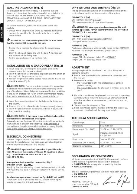
DIP-SWITCHES AND JUMPERS (Fig. 3)<br />
The dip-switches and jumpers on the electronic circuits of the<br />
photocells are used to set the operation of the system.<br />
DIP-SWITCH 1 (RX)<br />
ON - normal operation (DEFAULT)<br />
OFF - slower operation (for use when it snows)<br />
m ATTENTION: slow operation is not compatible with<br />
synchro operation. NEVER set DIP-SWITCH 1 to OFF when<br />
DIP-SWITCH 2 is set to ON<br />
DIP-SWITCH 2 (RX)<br />
OFF - NON synchronized operation (DEFAULT)<br />
ON - synchronized operation<br />
JUMPER J2 (RX)<br />
Position A - relay output with normally closed contact (DEFAULT)<br />
Position B - relay output with normally open contact<br />
JUMPER J1 (TX)<br />
Jumper OFF - for distances below 15 m (DEFAULT)<br />
Jumper ON - for distances above 15 m<br />
INSTALLATION ON A GARDO PILLAR (Fig. 2)<br />
1. Install the pillars, following the instructions given in the<br />
relevant instruction manual enclosed.<br />
2. Insert the photocell (or photocells, <strong>de</strong>pending on the length of<br />
the strip) into the grooves in the strip.<br />
3. Position the photocell at the <strong>de</strong>sired height and fix it using the<br />
special V screws (Fig.2).<br />
m PLEASE NOTE: Current regulations require the recognition<br />
of obstacles with different minimum heights <strong>de</strong>pending on the<br />
type of installation: 30 cm (height recommen<strong>de</strong>d for the installation<br />
of the 20 cm photocell) or 70 cm (50 cm recommen<strong>de</strong>d height).<br />
Refer to the regulations specific for the type of installation.<br />
4. Insert the connection cables into the hole on the bottom of<br />
the column.<br />
5. Connect the photocells and make the necessary adjustments.<br />
6. Insert the plastic front of the column and sli<strong>de</strong> it down and<br />
then insert the top plug<br />
m PLEASE NOTE: If the signal is not sufficient, check that<br />
the transmitter and receiver are aligned.<br />
Optionally, remove the cover B from the photocell inserted in the<br />
pillar and held in place by the upper cap. If the photocell is<br />
inserted insi<strong>de</strong> the pillar on which there is an accessory fitted in<br />
place of the upper cap, DO NOT remove the cover.<br />
ELECTRICAL CONNECTIONS<br />
The new range of <strong>de</strong>vices is equipped with a synchronism circuit<br />
allowing the installation of two pairs, even very close together,<br />
without them interfering with one another.<br />
m WARNING: synchronized operation is possible only<br />
with AC power: the supply of TX and RX must be in phase<br />
(e.g. TX earth with RX earth and 24 V AC TX<br />
with 24 V AC RX).<br />
Non-synchronised operation - connect as Fig. 5<br />
(DIP2 set to OFF - DEFAULT)<br />
Supply by direct or alternating current the two pairs of photocells<br />
and install the two pairs in the reverse or<strong>de</strong>r with respect to one<br />
another.<br />
Synchronised operation - connect as Fig. 4 (DIP2 set to ON)<br />
Supply both pairs of photocells with AC current, inverting the<br />
polarity between the first and second pairs.<br />
ADJUSTMENT<br />
Having completed the installation, check that the system is<br />
operating correctly:<br />
1. Ensure there are no obstacles between the transmitter and<br />
the receiver.<br />
2. Power-up the system:<br />
- The receiver LED is off: The photocell is not centred;<br />
perform centring.<br />
- The receiver LED is on: the photocell is centred, move on to<br />
part 3.<br />
3. Place the cover B over the photocell and ensure it is operating<br />
correctly without removing the adhesive attenuation filter C<br />
(the filter simulates adverse weather conditions such as rain,<br />
fog etc.)<br />
4. Then remove the attenuation filter.<br />
5. Break the infrared beam a number of times: the receiver LED<br />
must switch itself off and the relay must switch.<br />
TECHNICAL SPECIFICATIONS<br />
Optical range<br />
Dimensions<br />
Power supply (VIN - GND)<br />
Signal<br />
DECLARATION OF CONFORMITY<br />
<strong>V2</strong> S.p.A. hereby <strong>de</strong>clare that SENSIVA-XS equipment conforms<br />
to the essential requirements established in directives:<br />
• 2004/108/EC electromagnetic compatibility directive<br />
• RoHS2 2011/65/EC<br />
and that the following technical standards have been applied<br />
• EN 61000-6-2<br />
• EN 61000-6-3<br />
Racconigi, 14/06/2012<br />
Legal representative, <strong>V2</strong> S.p.A.<br />
Cosimo De Falco<br />
25 m<br />
84x29x24 mm<br />
12÷24 Vac / 12÷36 Vdc<br />
modulated infrared 2 KHz<br />
l = 940 nm<br />
Relay contact<br />
1A max 30 VDC<br />
Absorption (VIN = 24Vdc) TX 15 mA RX 20 mA<br />
Operating temperature -20° + 60° C