"VARIO" Paraleverstrebe / Paralever Torque Arm / Bras ... - Wunderlich
"VARIO" Paraleverstrebe / Paralever Torque Arm / Bras ... - Wunderlich
"VARIO" Paraleverstrebe / Paralever Torque Arm / Bras ... - Wunderlich

You also want an ePaper? Increase the reach of your titles
YUMPU automatically turns print PDFs into web optimized ePapers that Google loves.
Vielen Dank für Ihr Vertrauen zu<br />
unserem Produkt.<br />
Zunächst muß das Fahrzeug auf den Hauptständer<br />
gestellt werden oder so aufgebockt werden,<br />
daß das Hinterrad komplett entlastet werden<br />
kann. Zum entgültigen festziehen der <strong>Paralever</strong>schrauben<br />
wird eine zweite Person benötigt.<br />
1. Demontieren Sie zunächst das Hinterrad,<br />
die Bremsleitungsabdeckung und die hintere<br />
Befestigungsschraube (Bild A1). Durch leichtes<br />
auf und ab bewegen des Kardangehäuses<br />
lässt sich die Schraube, nach entfernen<br />
der Mutter, leichter herausziehen.<br />
2. Nun können Sie die vordere Befestigungsschraube<br />
(Bild A2) demontieren und die<br />
alte <strong><strong>Paralever</strong>strebe</strong> entfernen. Befestigen<br />
Sie jetzt die neue <strong><strong>Paralever</strong>strebe</strong> mit der<br />
Original-Schraube vorne lose (nur handfest!!)<br />
am Fahrzeug (B2).<br />
3. Heben Sie das Kardangehäuse soweit an,<br />
daß die Bohrung des Einstellexzenters mit<br />
der Kardanaufnahme fluchtet, setzen Sie die<br />
neue Befestigungsschraube, U-Scheibe und<br />
Mutter ein und ziehen sie handfest an (B1).<br />
4. Montieren Sie die Bremsschlauchabdeckung<br />
mit den Originalschrauben oder ggf. mit den<br />
mitgelieferten Schrauben M5 an die Strebe.<br />
Montieren Sie das Hinterrad wieder an.<br />
Hinterradschrauben über Kreuz mit 60 Nm<br />
anziehen.<br />
5. Stellen Sie den Exzenter nach ihren Wünschen<br />
ein und drehen Sie die Klemmschrauben<br />
mit 10 Nm und Schraubensicherung fest<br />
(Bild C + D). Hinweis: Die aufgedruckte Skala<br />
zeigt, um wieviel mm die Strebe gekürzt/<br />
verlängert wird.<br />
In der Mittelposition („0“, Bild C2) ist die<br />
Strebe in der Originalposition.<br />
Im Uhrzeigersinn drehen (max. position „7“,<br />
Bild C1): Strebe länger = Fahrzeug höher.<br />
Gegen Uhrzeigersinn drehen (max. position<br />
„7“, Bild C3): Strebe verkürzt = Fahrzeug<br />
niedriger.<br />
6. Nehmen Sie das Fahrzeug vom Hauptständer<br />
und lösen Sie die hintere Befestigungsschraube<br />
(Bild B1).<br />
7. Belasten Sie das Fahrzeug mit ca. 80 Kg<br />
(Die zweite Person sitzt auf Beifahrerbank).<br />
Drehen Sie so die Befestigungsschraube (D1)<br />
mit 16 Nm und Schraube (B2) mit 43 Nm fest.<br />
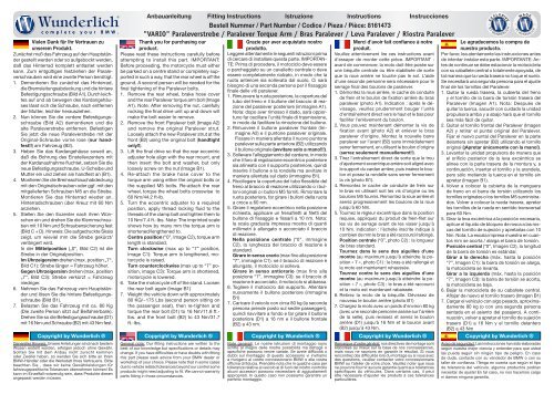
Anbauanleitung Fitting Instructions Istruzione Instructions Instrucciones<br />
Bestell Nummer / Part Number / Codice / Pieza / Pièce: 8161473<br />
"VARIO" <strong><strong>Paralever</strong>strebe</strong> / <strong>Paralever</strong> <strong>Torque</strong> <strong>Arm</strong> / <strong>Bras</strong> <strong>Paralever</strong> / Leva <strong>Paralever</strong> / Riostra <strong>Paralever</strong><br />
Grazie per aver acquistato nostro<br />
Merci d’avoir fait confiance à notre<br />
prodotto.<br />
produit.<br />
Leggere attentamente le seguenti istruzioni prima Veuillez attentivement lire ces instructions avant<br />
di cercare di installare questa parte. IMPORTAN- d’essayer de monter cette pièce. IMPORTANT :<br />
TE: Prima di procedere, il motociclo deve essere avant de commencer, la moto doit être posée sur<br />
o parcheggiato su un cavalletto centrale o deve une béquille centrale ou être stabilisée de sorte<br />
essere completamente rialzato, in modo che la que la roue arrière ne touche pas le sol. L’aide<br />
ruota anteriore sia sollevata dal suolo. Ci sarà d’une seconde personne sera nécessaire pour le<br />
bisogno di una seconda persona per il fissaggio serrage final des boulons de paralever.<br />
finale delle viti paralever.<br />
1. Démontez la roue arrière, le cache de conduite<br />
1. Rimuovere la ruota posteriore, la copertura del de frein et le boulon de fixation arrière du bras<br />
tubo del freno e il bullone del braccio di reazione<br />
del paralever posteriore (immagine A1).<br />
paralever (photo A1). Indication : après le dévissage,<br />
veuillez prudemment bouger l’unité<br />
Nota: dopo aver rimosso il dado, sarà opportuno<br />
far oscillare l’unità finale di trasmissione,<br />
d’entraînement direct vers le haut et le bas pour<br />
faciliter l’enlèvement du boulon.<br />
in modo da facilitare la rimozione del bullone.<br />
2. Vous pouvez maintenant démonter la vis de<br />
2. Rimuovere il bullone paralever frontale (Immagine<br />
A2) e il puntone paralever originale.<br />
fixation avant (photo A2) et enlever le bras<br />
paralever d’origine. Montez la nouvelle barre<br />
Fissare in maniera allentata il nuovo puntone<br />
paralever sulla parte anteriore (B2) utilizzando<br />
paralever sur l’avant (B2) sans immédiatement<br />
serrer fermement, en utilisant le boulon d’origine<br />
il bullone originale (avvitare solo a mano!!!).<br />
3. Sollevare l’alloggiamento del cardano, in modo<br />
(serrez seulement manuellement!!).<br />
che il foro di regolazione eccentrico posteriore<br />
3. Tirez l’entraînement direct de sorte que le trou<br />
sia allineato con il supporto posteriore, quindi d’ajustement excentrique arrière soit aligné avec<br />
inserire il bullone e la rondella ma avvitare in le support du cardan arrière, puis insérez le boulon<br />
et posez la rondelle sans serrer fermement<br />
maniera allentata sul dado (immagine B1).<br />
4. Ricollegare la copertura del tubo flessibile del la vis (photo B1).<br />
freno al braccio di reazione utilizzando o i bulloni<br />
4. Remontez le cache de conduite de frein sur<br />
originali o i bulloni M5 forniti. Rimontare la le bras en utilisant soit les vis d’origine ou les<br />
ruota posteriore, far girare i bulloni della ruota boulons M5 fournis. Remontez la roue arrière et<br />
a croce a 60 nm.<br />
serrez progressivement les boulons de la roue<br />
5. Girare il regolatore eccentrico nella posizione jusqu’à 60 Nm.<br />
richiesta, applicare un frenafiletti ai filetti del 5. Tournez le régleur excentrique dans la position<br />
bullone di fissaggio e fissarli a 10 nm. Nota: requise, appliquez du produit de frein-filet sur<br />
la scala graduata impressa mostra di quanti les vis de serrage avant de les visser jusqu’à<br />
millimetri è allungato o accorciato il braccio 10 Nm. Indication : l’échelle inscrite indique à<br />
di reazione.<br />
combien de mm le bras a été raccourci/rallongé.<br />
Nella posizione centrale (“0”, immagine Position centrale (“0”, photo C2) : la longueur<br />
C2), la lunghezza del braccio di reazione è de bras standard.<br />
standard.<br />
Tournez dans le sens des aiguilles d’une<br />
Girare in senso orario (max fino alla posizione montre (au maximum jusqu’à atteindre la position<br />
« 7 », photo C1) : le bras a été rallongé et<br />
“7”, immagine C1): se il braccio di reazione è<br />
allungato, il motociclo si solleva.<br />
la moto est maintenant rehaussée.<br />
Girare in senso antiorario (max fino alla<br />
Tournez contre le sens des aiguilles d’une<br />
posizione “7”, immagine C3): se il braccio di<br />
montre (au maximum jusqu’à atteindre la position<br />
« 7 », photo C3) : le bras a été raccourci<br />
reazione è accorciato, il motociclo si abbassa.<br />
6. Togliere il motociclo dal supporto. Allentare<br />
et la moto est maintenant rabaissée.<br />
nuovamente il bullone posteriore (immagine<br />
6. Retirez la moto de la béquille. Dévissez de<br />
B1)<br />
nouveau le boulon arrière (photo B1)<br />
7. Caricare il veicolo con circa 80 kg (la seconda<br />
7. Chargez la moto avec un poids d’environ 80 kg<br />
persona prende posto sul sedile passeggeri),<br />
quindi riavvitare a fondo e far girare il bullone<br />
(avec une seconde personne assise sur l’arrière<br />
posteriore (D1) a 16 nm e il bullone frontale<br />
de la selle), puis revissez et serrez le boulon<br />
(B2) a 43 nm.<br />
arrière (D1) jusqu’à 16 Nm et le boulon avant<br />
(B2) jusqu’à 43 Nm.<br />
Thank you for purchasing our<br />
product.<br />
Please read these instructions carefully before<br />
attempting to install this part. IMPORTANT:<br />
Before proceeding, the motorcycle must either<br />
be parked on a centre stand or completely supported<br />
in such a way, that the rear wheel is off the<br />
ground. A second person will be needed for the<br />
final tightening of the <strong>Paralever</strong> bolts.<br />
1. Remove the rear wheel, brake hose cover<br />
and the rear <strong>Paralever</strong> torque arm bolt (Image<br />
A1). Note: After removing the nut, carefully<br />
rocking the final drive unit up and down will<br />
make the bolt easier to remove.<br />
2. Remove the front <strong>Paralever</strong> bolt (Image A2)<br />
and remove the original <strong>Paralever</strong> strut.<br />
Loosely attach the new <strong>Paralever</strong> strut at the<br />
front (B2) using the original bolt (handtight<br />
only!!).<br />
3. Lift the final drive so that the rear eccentric<br />
adjuster hole align with the rear mount, and<br />
then insert the bolt and washer, but only<br />
loosely screw on the nut (Image B1).<br />
4. Re-attach the brake hose cover to the<br />
torque arm using either the original bolts or<br />
the supplied M5 bolts. Re-attach the rear<br />
wheel, torque the wheel bolts crosswise to<br />
60 Nm/44.2 ft-lb.<br />
5. Turn the eccentric adjuster to a required<br />
position, apply thread locking fluid to the<br />
threads of the clamp bolt and tighten them to<br />
10 Nm/7.4 ft.-lbs. Note: The imprinted scale<br />
shows how by many mm the torque arm is<br />
shortened/lengthened to.<br />
Centre position (“0”, Image C2), torque arm<br />
length is standard.<br />
Turn clockwise (max up to “7” position,<br />
image C1): <strong>Torque</strong> arm is lengthened, motorcycle<br />
is raised.<br />
Turn counterclockwise (max up to “7” position,<br />
image C3): <strong>Torque</strong> arm is shortened,<br />
motorcycle is lowered.<br />
6. Take the motorcycle off of the stand. Loosen<br />
the rear bolt again (Image B1)<br />
7. Weight the vehicle down with approximately<br />
80 KG/~175 Lbs (second person sitting on<br />
the passenger seat), then re-tighten and<br />
torque the rear bolt (D1) to 16 Nm/11.8 ft.-<br />
lbs. and the front bolt (B2) to 43 Nm/31.7<br />
ft.-lbs.<br />
B Y<br />
I C H<br />
W U N D E R L<br />
Le agradecemos la compra de<br />
nuestro producto.<br />
Por favor, lea atentamente las instrucciones antes<br />
de intentar instalar esta parte. IMPORTANTE: Antes<br />
de continuar se debe estacionar la motocicleta<br />
con su caballete central o totalmente apoyada, de<br />
tal manera que la rueda trasera no toque el suelo.<br />
Se necesitará una segunda persona para el ajuste<br />
final de los tornillos del <strong>Paralever</strong>.<br />
1. Quitar la rueda trasera, la cubierta del freno<br />
y el tornillo de la barra de torsión trasera del<br />
<strong>Paralever</strong> (Imagen A1). Nota: Después de<br />
quitar la tuerca, sacudir con cuidado la unidad<br />
propulsora arriba y a abajo hará que el tornillo<br />
sea más fácil de quitar.<br />
2. Quitar el tornillo frontal del <strong>Paralever</strong> (Imagen<br />
A2) y retirar el puntal original del <strong>Paralever</strong>.<br />
Fijar el nuevo puntal del <strong>Paralever</strong> en la parte<br />
delantera sin apretar (B2) utilizando el tornillo<br />
original (¡Apretar únicamente con la mano!).<br />
3. Levantar la unidad propulsora de manera que<br />
el orificio posterior de la leva excéntrica se<br />
alinee con la parte trasera de la montura y, a<br />
continuación, insertar el tornillo y la arandela,<br />
pero sólo metiendo la tuerca en el tornillo sin<br />
apretar (Imagen B1).<br />
4. Volver a colocar la cubierta de la manguera<br />
de freno en el barra de torsión utilizando los<br />
tornillos originales o los tornillos M5 suministrados.<br />
Volver a colocar la rueda trasera, apretar<br />
los tornillos de la rueda en sentido transversal<br />
para 60 Nm.<br />
5. Girar la leva excéntrica a la posición necesaria,<br />
aplicar el líquido de bloqueo de rosca a las roscas<br />
del tornillo de sujeción y apretarlas con 10<br />
Nm. Nota: La escala impresa muestra en cuantos<br />
mm se acorta / alarga el barra de torsión.<br />
Posición central (“0”, Imagen C2), la longitud<br />
de la barra de torsión es estándar.<br />
Girar a la derecha (máx. hasta la posición<br />
“7”, Imagen C1): la barra de torsión se alarga,<br />
la motocicleta se levanta.<br />
Girar a la izquierda (máx. hasta la posición<br />
“7”, Imagen C3): la barra de torsión se acorta,<br />
la motocicleta se baja.<br />
6. Bajar la motocicleta de su caballete central.<br />
Aflojar de nuevo el tornillo trasero (Imagen B1)<br />
7. Cargar el vehículo con algo pesado, aproximadamente<br />
80 kg (o con una segunda persona<br />
sentada en el asiento del pasajero). A continuación,<br />
volver a apretar el tornillo de sujeción<br />
trasero (D1) a 16 Nm y el tornillo delantero<br />
(B2) a 43 Nm<br />
Copyright by <strong>Wunderlich</strong> ® Copyright by <strong>Wunderlich</strong> ® Copyright by <strong>Wunderlich</strong> ® Copyright by <strong>Wunderlich</strong> ® Copyright by <strong>Wunderlich</strong> ®<br />
Genereller Hinweis: Unsere Anleitungen sind nach bestem<br />
Wissen erstellt worden, erfolgen jedoch ohne Gewähr.<br />
Sollten Sie mit dem Anbau nicht zurecht kommen<br />
oder Zweifel haben, so wenden Sie sich bitte an Ihren<br />
BMW-Händler oder die Werkstatt Ihres Vertrauens. Bitte<br />
beachten Sie , dass wir keine Gewährleistungen für<br />
fahrzeugspezifische Toleranzen übernehmen können! Es<br />
kann im Einzelfall notwendig sein, dass Produkte diesen<br />
angepasst werden müssen.<br />
General note: Our fitting instructions are written to the<br />
best of our knowledge but specifications or details may<br />
change. If you have difficulties or have doubts with fitting<br />
this part please seek advice from your BMW dealer or<br />
workshop of your choice. Please note that in some cases<br />
due to vehicle related tolerances beyond our control some<br />
products might need adjusting to fit. We cannot warranty<br />
parts fitting in those circumstances.<br />
Note generali: Le nostre istruzioni di montaggio sono<br />
scritte al meglio delle nostre possibilità ma dettagli o<br />
specifiche possono venire variate. Se avete difficoltà o<br />
dubbi sul montaggio di questo accessorio vi invitiamo<br />
a rivolgervi al vostro concessionario BMW o alla vostra<br />
officina di fiducia. Prendete nota che in qualche caso per<br />
tolleranze relative al veicolo al di fuori del nostro controllo<br />
alcuni accessori possono necessitare di aggiustamenti<br />
appropriati. In questo caso non possiamo garantire un<br />
perfetto montaggio.<br />
Remarque d’ordre général: nos directives de montage sont<br />
élaborées au mieux sur la base de nos connaissances,<br />
mais nous ne saurions en garantir le résultat. Si vous<br />
rencontrez des difficultés lors du montage ou si vous avez<br />
des questions, veuillez contacter votre concessionnaire<br />
BMW ou l’atelier de votre choix. Veuillez noter que nous<br />
ne pouvons fournir aucune garantie quant aux tolérances<br />
spécifiques du véhicules. Dans certains cas, il peut<br />
être nécessaire d’ajuster les produits à ces tolérances<br />
particulières.<br />
Aviso de seguridad: Las instrucciones han sido elaboradas<br />
según nuestra mejor ciencia y entender para que usted<br />
las pueda seguir sin ningún tipo de peligro. En caso<br />
de duda, contacte con su vendedor de BMW o con su<br />
taller de confianza. !Tenga en cuenta que según el tipo<br />
de tolerancia del vehículo, algunos productos podrían<br />
necesitar de ajuste! En tal caso, no nos hacemos cargo<br />
ni damos ninguna garantía.
S<br />
A<br />
2<br />
B<br />
C1<br />
1<br />
1<br />
2<br />
D<br />
43 Nm/31.7 ft.-lbs.<br />
C2<br />
!<br />
10 Nm/7.4 ft.-lbs.<br />
C3<br />
1<br />
16 Nm/11.8 ft.-lbs.<br />
Copyright by <strong>Wunderlich</strong> ® Copyright by <strong>Wunderlich</strong> ® Copyright by <strong>Wunderlich</strong> ® Copyright by <strong>Wunderlich</strong> ® Copyright by <strong>Wunderlich</strong> ®<br />
News, Shop, Downloads + Informationen:<br />
www.wunderlich.de<br />
Kataloganforderung + Downloads:<br />
www.wunderlich.de/katalog<br />
Anleitung download (in Farbe):<br />
www.wunderlich.de/manuals<br />
Catalogue download (English):<br />
www.wunderlich.de/update<br />
General information, dealers and news:<br />
www.wunderlich.de/International<br />
Fitting instructions download (in full colour):<br />
www.wunderlich.de/manuals<br />
Download catalogo (italiano):<br />
www.wunderlich.de/update<br />
Informazioni generali, dealer e Novità:<br />
http://www.wunderlich.it<br />
Download istruzioni di montaggio (colore)<br />
www.wunderlich.de/manuals<br />
Télécharger les catalogues (francais):<br />
www.wunderlich.de/update<br />
Informations générales et distributeurs:<br />
www.wunderlich.fr<br />
Télécharger les instructions de montage (en couleurs)<br />
www.wunderlich.de/manuals<br />
Descargar los catálogos (español):<br />
www.wunderlich.de/update<br />
Informaciones generales, tiendas y noticias:<br />
www.wunderlich.de/International<br />
Descargar las instrucciones de montaje (color):<br />
www.wunderlich.de/manuals<br />
<strong>Wunderlich</strong> GmbH • Kranzweiherweg 12 • 53489 Sinzig•Gewerbepark • Germany • Tel. +49-(0)2642-97980 • Fax +49-(0)2642-9798 33 • e-mail wunderlich@wunderlich.de • web: www.wunderlich.de<br />
Geschäftsführer/Managing Directors: Erich <strong>Wunderlich</strong>, Alexander de la Motte • Amtsgericht Andernach • HRB 12314 • USTID-Nr./VAT-No. 01 DE 149 271 221