41533 Man off IS2500-5501 - Mase Generators of North America
41533 Man off IS2500-5501 - Mase Generators of North America
41533 Man off IS2500-5501 - Mase Generators of North America

Create successful ePaper yourself
Turn your PDF publications into a flip-book with our unique Google optimized e-Paper software.
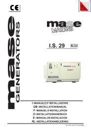
IS 2500<br />
IS 3500/3501<br />
IS 4500/4501<br />
IS 5500/<strong>5501</strong><br />
MANUALE DI SERVIZIO<br />
SERVICE MANUAL<br />
M.OFF.<strong>IS2500</strong><br />
22/10/01<br />
1
INDICE<br />
1 CARATTERISTI CHE TECNICHE 1 TECHNICAL FEATURES<br />
1.1 Motore<br />
Alternatore<br />
Dimensioni<br />
1.2 Identificazione del generatore<br />
Numero matricola del generatore<br />
numero matricola del motore<br />
1.3 Identificazione dei componenti<br />
1.4 Cruscotto comandi<br />
2 Motore<br />
3 Principio di funzionamento<br />
4 Controlli<br />
4.1 Avvolgimento di eccitazione<br />
4.2 Avvolgimento di potenza<br />
4.3 Avvolgimento di carica batteria<br />
4.4 Fusibile carica batteria<br />
4.5 Interruttore termico<br />
4.6 Avvolgimento di rotore<br />
4.7 Diodi di rotore<br />
4.8 Condensatore<br />
4.9 Scheda rele'<br />
4.9.1 Fusibile<br />
4.9.2 Rele'<br />
4.9.3 Diodi 1000V 1A<br />
4.9.4 Diodi 600V 6A<br />
4.9.5 Circuito stampato<br />
4.9.6 Scambiatore di calore<br />
4.9.7 Anodo di zinco<br />
4.9.8 Elettrovalvola<br />
4.9.9 Pompa gasolio<br />
4.9.10 Termostato acqua<br />
4.9.11 Pressostato olio<br />
4.9.12 Sonda A.T.T.<br />
4.9.13 Motorino avviamento<br />
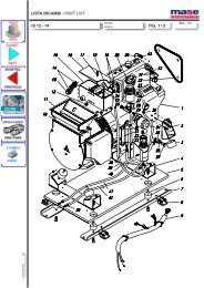
4.9.14Cinghia pompa acqua<br />
4.9.15 Pompa acqua<br />
4.9.16Regolazione dei giri<br />
5 Tabella guasti<br />
6 Schema elettrico<br />
1.1 Engine<br />
Alternator<br />
Dimensions<br />
1.2 Identification <strong>of</strong> generator<br />
Generator serial number<br />
Engine serial number<br />
1.3 Identification <strong>of</strong> components<br />
1.4 Control panel<br />
2 Engine<br />
3 Principle <strong>of</strong> power generation<br />
4 Service<br />
4.1 Excitation winding<br />
4.2 Power excitation<br />
4.3 Battery charger winding<br />
4.4 Battery charger fuse<br />
4.5 Alternator thermostat<br />
4.6 Rotor winding<br />
4.7 Rotor diode<br />
4.8 Capacitor<br />
4.9 Printed circuit relay<br />
4.9.1 Fuse<br />
4.9.2 Relay<br />
4.9.3 Diode 1000V 1A<br />
4.9.4 Diode 600V 6A<br />
4.9.5 Printed circuit<br />
4.9.6 Heat exchanger<br />
4.9.7 Zinc anodes<br />
4.9.8 Stop solenoid<br />
4.9.9 Diesel pump<br />
4.9.10 Water temperature switch<br />
4.9.11 Oil pressure switch<br />
4.9.12 A.T.T. Device<br />
4.9.13 Starter<br />
4.9.14Belt <strong>of</strong> the water pump<br />
4.9.15 Water pump<br />
4.9.16Engine speed adjustment<br />
5 Trouble shooting table<br />
6 Wiring diagram<br />
3
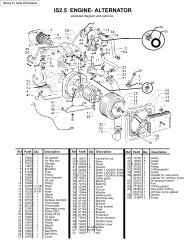
1)CARATTERISTICHE TECNICHE - TECHNICAL FEATURES<br />
1.1)MOTORE - ALTERNATORE - DIMENSIONI<br />
ENGINE - ALTERNATOR - DIMENSION<br />
MOTORE<br />
Modello<br />
Monocilindrico a scoppio 4 tempi<br />
diesel raffreddato ad aria<br />
Cilindrata<br />
Giri/minuto<br />
Alesaggio per corsa<br />
Potenza Hp<br />
Consumo g./Hp.h<br />
Alimentazione<br />
Sistema di avviamento<br />
Capacita' olio<br />
Inclinazione massima<br />
ALTERNATORE<br />
Sincrono , mon<strong>of</strong>ase, autoeccitato,<br />
due poli,senza spazzole<br />
Potenza continua<br />
Fattore di potenza<br />
Classe isolamento<br />
Frequenza Hz<br />
ENGINE<br />
Model<br />
1cylinder,4 stroke,internal<br />
combustion air-cooled diesel<br />
Displacement<br />
R.P.M.<br />
Bore for stroke<br />
Power Hp<br />
Fuel consumption g./Hp.h<br />
Fuel<br />
Starting system<br />
Oil capacity<br />
Max inclination<br />
ENGINE Yanmar Yanmar Yanmar<br />
L48 AE L70AE L100AE<br />
211cc. 296 cc. 406 cc.<br />
3000 3600 3000 3600 3000 3600<br />
70 X 55 78 X 62 86 X 70<br />
3,8/4,2 4,2/4,7 5,5/6,1 6,0/6,7 7,7/8,8 9/10<br />
220 230 220 230 220 230<br />
DIESEL DIESEL DIESEL<br />
ELETTRICO ELETTRICO ELETTRICO<br />
0,8 lt. 1,1 lt. 1,1 lt.<br />
20° 20° 20°<br />
ALTERNATOR<br />
Synchronous, self-excited,<br />
single phase, 2 poles,brushless<br />
Continuous output<br />
1700W 1900W 2700W 2900W 4000W 4800W<br />
Power factor<br />
Insulation class<br />
1<br />
F<br />
1<br />
F<br />
1<br />
F<br />
Frequecy Hz<br />
50 60 50 60 50 60<br />
DIMENSIONI<br />
Lunghezza<br />
Larghezza<br />
Altezza<br />
Peso<br />
DIMENSION<br />
Lenght<br />
Width<br />
Height<br />
Weight<br />
509mm 660mm 720mm<br />
406mm 460mm 490mm<br />
445mm 545mm 565mm<br />
65Kg 78Kg 110Kg<br />
4
1.2) IDENTIFICAZIONE DEL GENERATORE - IDENTIFICATION OF GENSET<br />
Il numero di matricola del generatore e'<br />
riportato su di un targhetta metallica<br />
rivettata sulla parte inferiore della cassa<br />
(Fig.A).<br />
Qualora non sia possibile identificare il<br />
generatore da questo numero, si faccia<br />
riferimento al numero di matricola del motore,<br />
punzonato sul basamento (Fig.B).<br />
Each generator has an identification<br />
number impressed on a small metallic plate<br />
and rivetted to the lower front side <strong>of</strong> the<br />
sound shield (Fig.A).<br />
In case identifying by this number becomes<br />
impossible, please note the engine number,<br />
die stamped on the crankcase (Fig.B)<br />
Fig.A<br />
Fig.B<br />
5
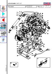
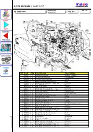
1.3) IDENTIFICAZIONE DEI COMPONENTI - IDENTIFICATION OF COMPONENTS<br />
Elementi della macchina (Fig.5)<br />
1) MOTORE<br />
2) ALTERNATORE<br />
3) CRUSCOTTO ALTERNATORE<br />
4) ELETTROVALVOLA DI ARRESTO<br />
5) POMPA ACQUA<br />
6) RITORNO COMBUSTIBILE<br />
7) LEVA ARRESTO MANUALE<br />
8) ASTA LIVELLO OLIO<br />
9) POMPA COMBUSTIBILE<br />
10) INGRESSO COMBUSTIBILE<br />
11) INGRESSO TUBAZIONE ACQUA<br />
12) PRESA ARIA<br />
13) INGRESSO CAVI ELETTRICI<br />
14) INGRESSO ACQUA<br />
15) TAPPO CARICO OLIO<br />
16) SCAMBIATORE DI CALORE<br />
17) TERMOSTATO ACQUA<br />
18) PRESSOSTATO OLIO<br />
Generator components (Fig.5)<br />
1) ENGINE<br />
2) ALTERNATOR<br />
3) ALTERNATOR CONTROL PANEL<br />
4) FUEL SOLENOID<br />
5) WATER PUMP<br />
6) FUEL RETURN<br />
7) STOP LEVEL<br />
8) DEEP STICK OIL<br />
9) FUEL PUMP<br />
10) FUEL FEED<br />
11) INPUT WATER CONNECTIONS<br />
12) AIR INLET<br />
13) INLET ELETTRIC CONNECTIONS<br />
14) INLET WATER<br />
15) OIL FILLING WP<br />
16) HEAT EXCHANGER<br />
17) WATER TEMPERATURE SWITCH<br />
18) OIL PRESSURE SWITCH<br />
6
1.4)CRUSCOTTO COMANDI<br />
1) CONTAORE<br />
2) PULSANTE OFF<br />
3) PULSANTE START<br />
4) PULSANTE ON<br />
5) LED PANNELLO ON (VERDE)<br />
6) LED USCITA GENERATORE (VERDE)<br />
7) LED PRESSIONE OLIO (ROSSO)<br />
8) LED TEMPERATURA MOTORE (ROSSO)<br />
9) LED TEMPERATURA GENERATORE (ROSSO)<br />
1.4) CONTROL PANEL<br />
1) HOURSMETER<br />
2) OFF BUTTON<br />
3) START BUTTON<br />
4) BUTTON ON<br />
5) PANEL ON LED (GREEN)<br />
6) GENERATOR OUTPUT LED (GREEN)<br />
7) OIL PRESSURE LED (RED)<br />
8) ENGINE TEMPERATURE LED (RED)<br />
9) GENERATOR TEMPERATURE LED (RED)<br />
7
2) MANUTENZIONE<br />
Per la durata e il corretto funzionamento del<br />
generatore è necessario rispettare il programma<br />
di controlli e manutenzione indicati nella tabella<br />
seguente.<br />
L'esecuzione di queste operazioni è descritta,<br />
per la parte relativa al motore, sul libretto uso e<br />
manutenzione o sul manuale d'<strong><strong>of</strong>f</strong>icina del<br />
costruttore del motore.<br />
Si ricorda inoltre che durante le normali operazioni<br />
di manutenzione (Montaggio/smontaggio)<br />
è necessario rispettare alcune regole generali,<br />
quindi:<br />
- rispettare le coppie di serraggio.<br />
- utilizzare grassi, olii, frenafiletti appropriati.<br />
- non lavare avvolgimenti o parti elettriche con<br />
acidi o sostanze corrosive.<br />
- spruzzare disossidanti sui contatti elettrici<br />
- rispettare la<br />
numerazione<br />
dei cavi.<br />
Se necessario<br />
annotarne la<br />
numerazione e<br />
la posizione.<br />
2) MAINTENANCE<br />
For the longevity and correct performance <strong>of</strong><br />
the generator, it is necessary to respect the<br />
check and maintenance program detailed out in<br />
the following tables.<br />
As regarding the engine, the maintenance operations<br />
are described in the use and maintenance<br />
manual and the workshop manual prepared<br />
by the engine manufacturer.<br />
Please note further that while involved in normal<br />
maintenance work <strong>of</strong> the generator (Dismounting/mounting)<br />
certain general rules must<br />
be adhered to:<br />
- respect the torque specifications.<br />
- use appropriate oil, grease and bonding agents.<br />
- do not clean windings or electrical parts with<br />
acid or other corroding substances.<br />
- spray deoxidizer on the electrical contact<br />
points<br />
- respect the<br />
numerical order<br />
<strong>of</strong> wires<br />
If necessary,<br />
note their numeration<br />
and<br />
position.<br />
8
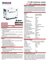
1) PRINCIPIO DI FUNZIONAMENTO<br />
3) PRINCIPLE OF POWER<br />
GENERATION<br />
1<br />
2<br />
I generatori della serie IS 2500 sono dotati di<br />
alternatori senza spazzole, sincroni, a due poli,<br />
autoregolati, autoeccitati, con condensatore<br />
(Fig. 1 Rif. 5) collegato con l'avvolgimento<br />
ausiliario di statore (Fig. 1 Rif. 3). Gli alternatori<br />
generano una tensione alternata, disponibile<br />
ai morsetti dell'avvolgimento principale (Fig.<br />
1 Rif. 4) a una frequenza di 50/60 Hz. (Corrispondenti<br />
ad una velocità del motore primo di<br />
3000/3600 giri) secondo il principio di seguito<br />
descritto.<br />
All'avviamento il magnetismo di rotore (magnetismo<br />
residuo del nucleo) induce nell'avvolgimento<br />
ausiliario di eccitazione (Fig. 1 Rif. 3)<br />
una tensione.<br />
Questa tensione è applicata al condensatore<br />
(Fig. 1 Rif. 5) e fa circolare nel circuito chiuso,<br />
costituito dal condensatore e dall'avvolgimento<br />
ausiliario, una corrente capacitiva.<br />
Questa corrente produce un campo magnetico<br />
che rafforza il magnetismo di rotore, generando<br />
in esso una tensione che, raddrizzata dai diodi,<br />
(Fig. 1 Rif. 2) fa circolare una corrente continua<br />
negli avvolgimenti induttori (Fig. 1 Rif. 1).<br />
Il campo magnetico rotante dovuto alla circolazione<br />
di questa corrente genera a sua volta<br />
nell'avvolgimento principale (Fig. 1 Rif. 4) la<br />
tensione nominale ai morsetti del generatore.<br />
I valori (intesi come percentuale dei valori<br />
nominali) di tensione e corrente disponibili ai<br />
morsetti hanno l'andamento riportato nel diagramma<br />
(Fig. 2). Come si può notare è possibile<br />
prelevare corrente fino al valore nominale a<br />
tensione praticamente costante (+/- 5%). Ed<br />
inoltre l'alternatore, ad una tensione non inferiore<br />
al 70-75% del valore nominale, è ancora in<br />
grado di fornire una corrente di picco pari a<br />
circa 3 volte il valore nominale.<br />
Questa caratteristica, tipica di questo alternatore<br />
è particolarmente utile nella fase di avviamento<br />
dei motori elettrici asincroni.<br />
IS 2500 generators are equipped with two pole<br />
synchronous brushless alternators. These alternators<br />
are also self-regulating and self-exciting<br />
with capacitor (Fig. 1 Ref. 5) connected to the<br />
auxiliary winding <strong>of</strong> the stator (Fig. 1 Ref. 3).<br />
The alternators generate an alternating voltage<br />
at the terminals <strong>of</strong> the main winding (Fig. 1Ref.<br />
4) having a frequency <strong>of</strong> 50 or 60 Hz. (Depending<br />
on whether the engine runs at 3000 or 3600<br />
R.P.M.).<br />
The generation <strong>of</strong> current is in accordance with<br />
the principle described here below:<br />
On starting the unit, the magnetic force <strong>of</strong> the<br />
rotor (residual magnetism <strong>of</strong> the nucleus) induces<br />
a voltage in the auxiliary winding <strong>of</strong><br />
excitation (Fig. 1 Ref. 3). This voltage is fed to<br />
the capacitor (Fig. 1 Ref. 5) which creates a<br />
capacitive current circulating in the closed circuit<br />
constituted <strong>of</strong> the capacitor and the auxiliary<br />
winding.<br />
This capacitive current, creates a magnetic field<br />
reinforcing the magnetism <strong>of</strong> the rotor, thus<br />
creating in it a voltage which rectified by the<br />
diodes (Fig. 1 Ref. 2) makes a D.C. current<br />
circulate in the induction windings (Fig. 1 Ref.<br />
1). As a result <strong>of</strong> which a rotating magnetic field<br />
is created which generates the rated output in<br />
the principal winding (Fig. 1 Ref. 4) and which<br />
can be tapped at the terminals.<br />
The voltage and current values (denoted in<br />
percentage terms <strong>of</strong> rated values are as shown in<br />
the diagram (Fig. 2).<br />
As you will note, it is possible to get energy up<br />
to the nominal value. With voltage practically<br />
constant (+/- 5%). Moreover, the alternator at<br />
a voltage not inferior to 70-75% <strong>of</strong> the rated<br />
voltage, is able to furnish, as initial power rush,<br />
up to 3 times the rated amperage.<br />
As we know, this initial rush, typical <strong>of</strong> this<br />
alternator is extremely important to start asynchronous<br />
motors.<br />
9
4) CONTROLLI<br />
Tutte le misure di resistenza si intendono eseguite<br />
ad alternatore freddo, temperatura ambiente<br />
10 - 30 °C e con strumentazione tale da<br />
permettere la lettura dei valori indicati.<br />
La tolleranza rispetto ai valori riportati è indicativamente<br />
± 10%.<br />
letture approssimative, eseguite con strumenti<br />
di portata non adeguata, possono unicamente<br />
indicare la continuità dell'avvolgimento ma non<br />
danno indicazioni su eventuali corto circuiti.<br />
N.B.<br />
Oltre alle possibilità di guasto che<br />
sono indicate in seguito si può<br />
presentare il caso di uno o più<br />
avvolgimenti a massa. Si consiglia<br />
quindi di controllare questa<br />
eventualità verificando con un<br />
tester che non ci sia continuità fra<br />
le estremità dei vari avvolgimenti<br />
(identificati nei paragrafi<br />
successivi) e massa.<br />
4) SERVICE<br />
All the resistances must be measured when the<br />
alternator is cold, ambient temperature between<br />
10 - 30 °C and with an instrument that allows<br />
reading <strong>of</strong> given values.<br />
The tolerance against the reported values is<br />
around ± 10%.<br />
Readings taken with simpler instruments can<br />
only indicate the continuity <strong>of</strong> the winding but<br />
cannot indicate the presence <strong>of</strong> short circuits.<br />
N.B.<br />
Apart from the possibilities<br />
suggested here-by, one or more<br />
windings could also be grounded<br />
causing a failure.<br />
We suggest therefore to check by<br />
means <strong>of</strong> a tester that there is no<br />
continuity between the extremities<br />
<strong>of</strong> the windings and ground.<br />
4.1)Excitation winding<br />
4.1)Avvolgimento di eccitazione<br />
Caratteristiche - Characteristics:<br />
IS 2500<br />
50 Hz 4.30 Ohm<br />
60 Hz 3.80 Ohm<br />
IS 3500/1 50 Hz 2.37 Ohm<br />
60 Hz 1.86 Ohm<br />
IS 4500/1 50 Hz 1.06 Ohm<br />
IS 5500/1 60 Hz 0.75 Ohm<br />
Fig. 3<br />
Metodo di controllo<br />
- Scollegare dal condensatore i due cavi (BLU)<br />
provenienti dallo statore (Fig. 3).<br />
- Verificare che la resistenza fra le estremità dei<br />
due cavi rientri nei valori indicati in tabella.<br />
RIMEDIO: Sostituire lo statore.<br />
Testing method:<br />
-Disconnect from the capacitor the two wires<br />
(color: BLUE) coming from the stator (Fig. 3).<br />
-Verify that the resistance values between these<br />
two wire terminals are within the limits as<br />
reported in the table above.<br />
REMEDY: Replace the stator.<br />
10
4.2)Avvolgimento di potenza<br />
4.2) Power winding<br />
Caratteristiche - Characteristic:<br />
IS 2500<br />
50 Hz 1.00 Ohm<br />
60 Hz 0.90 Ohm<br />
IS 3500/1 50 Hz 0.52 Ohm<br />
60 Hz 0.44 Ohm<br />
IS 4500/1 50 Hz 0.20 Ohm<br />
IS 5500/1 60 Hz 0.18 Ohm<br />
Fig. 4<br />
Metodo di controllo:<br />
-Scollegare dalla morsettiera i cavi di potenza<br />
contrassegnati dalle lettere P 1<br />
F 1<br />
P 2<br />
F 2<br />
(Fig. 4).<br />
-Verificare che la resistenza fra le estremità di<br />
entrambe le coppie di cavi P 1<br />
F 1<br />
e P 2<br />
F 2<br />
rientri nei<br />
valori indicati in tabella.<br />
N.B. La resistenza totale dell'avvolgimento (nel<br />
collegamento 220 V o 240 V) si misura<br />
ponticellando F 1<br />
e P 2<br />
. La misura effettuata fra i<br />
punti P 1<br />
e F 2<br />
sarà il doppio del valore indicato in<br />
tabella.<br />
RIMEDIO: Sostituire lo statore<br />
4.3)Avvolgimento di carica batteria<br />
Caratteristiche - Characteristic:<br />
IS 2500<br />
50 Hz 0.15 Ohm 13 V<br />
60 Hz 0.10 Ohm 13 V<br />
IS 3500/1 50 Hz 0.18 Ohm 13 V<br />
60 Hz 0.10 Ohm 13 V<br />
IS 4500/1 50 Hz 0.10 Ohm 13 V<br />
IS 5500/1 60 Hz 0.10 Ohm 13 V<br />
Testing method:<br />
- Disconnect from the terminal board, the wires<br />
coming from the stator, marked by the letters P 1<br />
F 1<br />
P 2<br />
F 2<br />
(Fig. 4).<br />
- Verify that the resistance values between the<br />
two pairs <strong>of</strong> wire terminals P 1<br />
F 1<br />
and P 2<br />
F 2<br />
are<br />
within the limits as reported in the table above.<br />
N.B. The total resistance value for power winding<br />
(220 V 240 V) is measured connecting F 1<br />
and P 2<br />
. the resistance value measured between<br />
P 1<br />
and F 2<br />
is double <strong>of</strong> that indicated in the table<br />
above.<br />
REMEDY: Replace the stator.<br />
4.3)Battery charger winding (stator)<br />
Fig. 5<br />
Metodo di controllo:<br />
-Scollegare i cavi dal regolatore (Fig. 5) e<br />
verificare che la resistenza fra i cavi verdi rientri<br />
nei valori indicati in tabella.<br />
IN ALTERNATIVA:<br />
-Verificare che fra i cavi verdi la tensione alternata<br />
rientri nei valori indicati in tabella.<br />
Testing method:<br />
Disconnect the wires coming from the regulator<br />
(Fig. 5) and verify that the resistance values<br />
between the green wires are within the limits<br />
indicated in the table above.<br />
AS AN ALTERNATIVE:<br />
-Verify that the voltage between the GREEN<br />
wires is as reported above.<br />
11
N.B.: Eseguire questa misura senza carichi<br />
applicati al generatore, con batteria d'avviamento<br />
inserita e dopo aver atteso qualche minuto<br />
dall'avviamento.<br />
RIMEDIO: Sostituire lo statore.<br />
IMPORTANTE<br />
Il circuito del carica batteria è<br />
dotato di un regolatore elettronico<br />
di carica in grado di erogare max.<br />
15 A a 12 V; in caso di anomalia<br />
nella ricarica della batteria dopo<br />
aver controllato la resistenza<br />
dell'avvolgimento ed il fusibile, di<br />
consiglia di sostituire il regolatore.<br />
N.B.: The above measurements must be done<br />
after few minutes from the starting, without any<br />
load applied to the generator and with the<br />
starting battery connected.<br />
REMEDY: Replace the stator.<br />
WARNING<br />
The battery charger circuit,<br />
equipped with an electronic charger<br />
regulator, has a max. output <strong>of</strong> 15<br />
A at 12 V. If the defect on the<br />
battery charger circuit results not<br />
to depend on the fuse or on the<br />
stator windings, it's advisable to<br />
replace the regulator<br />
4.4) Fusibile carica batteria<br />
Caratteristiche - Characteristics:<br />
4.4) Battery charger fuse<br />
Fig. 6<br />
IS 2500<br />
50 Hz 20 Amp<br />
60 Hz 20 Amp<br />
IS 3500/1 50 Hz 30 Amp<br />
60 Hz 30 Amp<br />
IS 4500/1 50 Hz 30 Amp<br />
IS 5500/1 60 Hz 30 Amp<br />
Metodo di controllo:<br />
-Verificare la continuità alle estremità del fusibile<br />
(Fig. 6 Rif.1).<br />
RIMEIDO: Sostituire il fusibile.<br />
Testing method:<br />
-Verify the continuity at its terminals (Fig. 6<br />
Ref.1).<br />
REMEDY: Replace the fuse.<br />
4.5) Interruttore termico (statore)<br />
Caratteristiche :<br />
Normalmente chiuso. Temperatura d'intervento<br />
160 °C.<br />
4.5) Thermal switch (stator)<br />
Characteristics:<br />
Normally closed. Trips at a temperature <strong>of</strong> 160 °C<br />
Fig. 7<br />
12
Metodo di controllo:<br />
-Scollegare dalla morsettiera i due cavi (NERI)<br />
provenienti dallo statore ai morsetti N. 17 e N.<br />
18 (Fig. 7).<br />
-Verificare la continuità fra le due estremità dei<br />
cavi.<br />
RIMEDIO: Sostituire lo statore<br />
N.B.: L'interruttore termico può intervenire per<br />
sovraccarico o per sovratemperatura.<br />
Verificare quindi, se è necessario, i carichi applicati<br />
e la temperatura d'esercizio del generatore,<br />
con particolare attenzione alla sua installazione.<br />
Testing method:<br />
-Disconnect from the terminal board, the two<br />
wires (colour: Black), connecting terminals No.<br />
17 and 18 (Fig. 7) to the stator.<br />
-Check that there is continuity between the two<br />
ends <strong>of</strong> the two wires.<br />
REMEDY: Replace the stator.<br />
N.B.: The thermal switch can trip because <strong>of</strong><br />
overload or overheat. It's hence important to<br />
verify the loads connected and the running<br />
temperature <strong>of</strong> the generator with an eye on<br />
installation to verify if it may have contributed<br />
to the problem.<br />
4.6) Avvolgimento di rotore (n°2)<br />
4.6) Rotor winding (no. 2)<br />
Caratteristiche - Caracteristics:<br />
IS 2500<br />
50 Hz 0.50 Ohm<br />
60 Hz 0.50 Ohm<br />
IS 3500/1 50 Hz 0.57 Ohm<br />
60 Hz 0.57 Ohm<br />
IS 4500/1 50 Hz 0.74 Ohm<br />
IS 5500/1 60 Hz 0.74 Ohm<br />
Fig. 8<br />
Metodo di controllo:<br />
-Scollegare le estremità dell'avvolgimento di<br />
rotore.<br />
-Verificare che la resistenza fra le due estremità<br />
rientri nei valori indicati. (Fig. 8).<br />
RIMEDIO: Sostituire lo statore<br />
IMPORTANTE<br />
La mancanza di tensione in uscita<br />
può essere causata<br />
eccezionalmente dalla mancanza o<br />
insufficienza di magnetismo<br />
residuo del rotore.<br />
Come primo intervento si consiglia,<br />
con il generatore in moto, di<br />
collegare per un attimo una batteria<br />
12 V ai terminali del condensatore<br />
o, all'uscita di potenza.<br />
In questo modo il rotore viene<br />
istantaneamente magnetizzato.<br />
Testing method:<br />
-Disconnect the wires <strong>of</strong> the rotor winding.<br />
-Verify that the resistance value between the<br />
wire terminals is as reported in the table above<br />
(Fig. 8).<br />
REMEDY: Replace the rotor.<br />
WARNING<br />
If there is still no power it could<br />
depend very rarely on the<br />
dissipation <strong>of</strong> the residual<br />
magnetism <strong>of</strong> the rotor.<br />
So as to solve the problem it is<br />
advisable to connect a 12 V battery<br />
to the capacitor terminals or to the<br />
power terminals, for a few instants,<br />
while the generator is running. The<br />
rotor will get magnetized<br />
immediately.<br />
13
4.7) Diodi di rotore<br />
Caratteristiche : 21 A 800 V<br />
Direzione normale<br />
0.66 Ohm<br />
Direzione inversa<br />
<strong>Man</strong>canza di cont.<br />
4.7) Rotor diodes<br />
Caracteristics: 21 A 800 V<br />
Normal direction<br />
0.66 Ohm<br />
Reverse direction<br />
No continuity.<br />
Fig. 9<br />
Metodo di controllo:<br />
-Scollegare il cavo dal diodo.<br />
-Verificare che la resistenza fra (+) e massa<br />
rientri nei valori indicati. (Fig. 9).<br />
-Verificare che invertendo i puntali del tester<br />
non ci sia continuità.<br />
RIMEDIO: Sostituire il diodo.<br />
N.B.: In caso di diodo difettoso è necessario<br />
sostituire anche il varistore (Fig. 9 Rif. 1) anche<br />
se apparentemente integro.<br />
4.8) Condensatore<br />
Testing method:<br />
-Disconnect the wire from the diode.<br />
-Verify that the resistance value between (+)<br />
and ground is as reported in the table above.<br />
(Fig. 9).<br />
-Invert the tester terminals and verify that there<br />
is no continuity in the reverse direction.<br />
REMEDY: Replace the diode.<br />
N.B.: If the diode is defective it is necessary to<br />
replace the varistor too, (Fig. 9 Ref. 1), even if<br />
it appears intact.<br />
4.8) Capacitor<br />
Caratteristiche - Characteristics:<br />
IS 2500<br />
12.5 micr<strong>of</strong>arad 500 V<br />
IS 3500/1 20 micr<strong>of</strong>arad 500 V<br />
IS 4500/1 35 micr<strong>of</strong>arad 500 V<br />
IS 5500/1 35 micr<strong>of</strong>arad 500 V<br />
Fig. 10<br />
Metodo di controllo:<br />
-Scollegare i cavi (BLU) dal condensatore.<br />
-Posizionare il tester sul valore più alto della<br />
scala ohmica (x1000), la lancetta dovrà oscillare<br />
velocemente avanti e indietro nel momento in<br />
cui i puntali del tester toccheranno i terminali<br />
del condensatore (Fig. 10).<br />
Testing method:<br />
-Disconnect the wires (colour: BLUE) <strong>of</strong> the<br />
capacitor.<br />
-With the tester set to (x1000) connect it with<br />
the capacitor terminals. The needle must swing<br />
sharply away an back the moment the tester<br />
prods touch the capacitor terminals (Fig. 10).<br />
14
N.B.: Con questa prova si verifica che il condensatore<br />
non sia in cortocircuito o interrotto.<br />
Una diminuzione di capacità, che ha come effetto<br />
una diminuzione della tensione a vuoto, è<br />
difficilmente valutabile.<br />
In questo caso, verificate le altre possibili cause,<br />
si consiglia di sostituire il condensatore.<br />
RIMEDIO: Sostituire il condensatore<br />
N.B.: With this test, the capacitor is checked for<br />
short circuits/interruptions. If however the capacity<br />
is diminished, resulting in a voltage drop<br />
under no load condition, this test cannot diagnose<br />
the problem. In this case we suggest that<br />
the capacitor be replaced after having checked<br />
for other possible faults.<br />
REMEDY: Replace the capacitor.<br />
4.9) Scheda relè 4.9) Relay p.c. board<br />
1) Fusibile 1 A / Fuse 1 A<br />
2) Relè elettrovalvola e pompa nafta /<br />
Fuel solenoid and fuel pump relay<br />
3) Relè avviamento / Start relay<br />
4) Diodi / Diodes<br />
Fig. 11<br />
4.9.1) Fusibile<br />
Caratteristiche: 1 A<br />
4.9.1) Fuse<br />
Caracteristics: 1 A<br />
Fig. 12<br />
Metodo di controllo:<br />
-Verificare la continuità alle estremità del fusibile<br />
(Fig. 12 Rif.1).<br />
RIMEDIO: Sostituire il fusibile<br />
Testing method:<br />
-Verify the continuity at its terminals (Fig. 12<br />
Ref.1).<br />
REMEDY: Replace the fuse<br />
15
4.9.2) Relè<br />
4.9.2) Relay<br />
Caratteristiche-Characteristic: 12 V<br />
30A<br />
30 - 87 Contatto normalmente APERTO<br />
30 - 87 Contact normally OPEN<br />
30 - 87b Contatto normalmente CHIUSO<br />
30 - 87b Contact normally CLOSED<br />
Fig. 13<br />
Metodo di controllo:<br />
-Disinserire il relè.<br />
-Verificare che fra i punti 85 -86 vi sia continuità<br />
(Fig. 13).<br />
-Verificare che eccitando la bobina (12 v ai<br />
morsetti 85 - 86), il contatto 30 - 87 CHIUDE,<br />
mentre il contatto 30 - 87b APRE.<br />
RIMEDIO: Sostituire il relè<br />
Testing method:<br />
-Remove the relay.<br />
-Verify that there is continuity between 85 and<br />
86 (Fig. 13).<br />
-Verify that exciting the coil (apply 12 V to<br />
terminals 85 and 86) makes terminals 30 and 87<br />
CLOSE and terminal 30 and 87b OPEN.<br />
REMEDY: Replace the relay.<br />
4.9.3) Diodi<br />
Caratteristiche: 1 A 1000 V<br />
4.9.3) Diodes<br />
Caracteristics: 1 A 1000 V<br />
Direzione normale<br />
Direzione inversa<br />
0.850 Ohm<br />
<strong>Man</strong>canza di cont.<br />
Normal direction<br />
Reverse direction<br />
0.850 Ohm<br />
No continuity<br />
Fig. 14<br />
Metodo di controllo:<br />
-Smontare i relè.<br />
-Scollegare i cavi dalla morsettiera (Fig. 14).<br />
-Verificare che la resistenza fra le due estremità<br />
rientri nei valori indicati.<br />
-Verificare che invertendo i puntali del tester<br />
non ci sia più continuità.<br />
RIMEDIO: Sostituire il diodo<br />
Testing method:<br />
-Remove the relays<br />
-Disconnect the wires from the terminal board.<br />
-Verify that the resistance value between the<br />
diode's terminal is as reported above.<br />
-Invert the tester prods and verify that there is<br />
no continuity in.<br />
REMEDY: Replace the diode.<br />
16
4.9.3)Diodi<br />
4.9.3)Diodes<br />
Caratteristiche: 6A 600V<br />
Characteristics: 6A 600V<br />
Direzione normale<br />
0.75 Ohm<br />
Direzione inversa <strong>Man</strong>canza di cont.<br />
Normal direction<br />
Reverse direction<br />
0.75 Ohm<br />
No continuity<br />
Metodo di controllo:<br />
-Verificare che la resistenza fra le due estremita'<br />
rientri nei valori indicati(Fig.15)<br />
-Verificare che invertendo i puntali del<br />
tester non ci sia piu' continuita'.<br />
RIMEDIO: Sostituire il diodo<br />
Testing method:<br />
-Verify that the resistance value between it's<br />
terminals is as reported above(Fig.15)<br />
-Invert the tester terminals and verify that there<br />
is no continuity in the reverse<br />
REMEDY:Replace the diode<br />
Fig.15<br />
17
4.9.5) Circuito stampato 4.9.5) Printed circuit<br />
Metodo di controllo:<br />
-Verificare tutte le funzioni del generatore (avviamento,<br />
arresto, dispositivi di sicurezza).<br />
-Verificare le possibili cause di mancato<br />
funzionamento(batteria, motorino, avviamento,<br />
pressostato, termostato, interruttore termico<br />
fusibile, scheda rele')<br />
RIMEDIO: Sostituire il circuito stampato<br />
(Fig.16 Rif.1)<br />
Testing method:<br />
-Verify all generator's functions (start, stop,<br />
safety devices).<br />
-Verify all the possible causes <strong>of</strong> not proper<br />
running (battery,starter, oil pressure switch,<br />
water temperature switch, alternator thermostat,<br />
relay board fuse)<br />
REMEDY: Replace the printed circuit .(Fig.16<br />
Ref.1)<br />
Fig. 16<br />
Quando il gruppo si arresta, per l'intervento<br />
di una protezione, sul display del pannello<br />
comandi scompare l'indicazione delle ore di<br />
funzionamento e compare un codice ad indicare<br />
la causa dell'arresto del gruppo<br />
elettrogeno.<br />
Nella tabella sono riportati tutti i codici e il<br />
loro significato<br />
When the unit stops because <strong>of</strong> an alarm<br />
intervention, the operating time indication<br />
disappears from the control panel display and<br />
a code appears to indicate the cause <strong>of</strong> the<br />
generator stop.<br />
In the table below all the codes and their<br />
meaning are listed.<br />
TABELLA CODICI DI ALLARME<br />
TABLE OF ALARM CODES<br />
CODICE<br />
CAUSA INTERVENTO PROTEZIONE<br />
CODE<br />
REASON FOR ALARM<br />
E - 80<br />
E - 81<br />
E - 82<br />
E - 83<br />
E - 85<br />
E - 87<br />
batt<br />
<strong>Man</strong>canza tensione gruppo<br />
Bassa pressione olio<br />
Alta temperatura motore<br />
Alta temperatura alternatore<br />
Sovraccarico gruppo elettrogeno<br />
A 30 sec. dall'avvio il gruppo non<br />
raggiunge 80% della tensione nominale<br />
Bassa tensione di batteria<br />
E - 80<br />
E - 81<br />
E - 82<br />
E - 83<br />
E - 85<br />
E - 87<br />
batt<br />
No power to genset<br />
Oil pressure low<br />
Motor temperature high<br />
Alternator temperature high<br />
Generator set overloaded<br />
After 30 s. from start-up, the genset<br />
has not reached 80% <strong>of</strong> rated voltage<br />
Battery voltage low<br />
18
Cod. . E - 80 Tale codice indica che il gruppo si<br />
è arrestato per mancanza completa di tensione<br />
= 0 V. La comparsa di tale codice sta ad indicare:<br />
- che il pannello di comando non è in grado di<br />
leggere la tensione del l'alternatore per l'interruzione<br />
di una connessione elettrica;<br />
- che l'alternatore è danneggiato.<br />
Cod. . E - 81 Tale codice indica che il gruppo si<br />
è arrestato per pressione dell'impianto di<br />
lubrificazione del motore è insufficiente.<br />
Cod. . E - 82 Tale codice indica che il gruppo si<br />
è arrestato perché il motore ha raggiunto temperature<br />
troppo elevate.<br />
Cod. . E - 83 Tale codice indica che il gruppo si<br />
è arrestato perché l'alternatore ha raggiunto<br />
temperature troppo elevate.<br />
Cod. . E - 85 Tale codice indica che il gruppo si<br />
è arrestato perché la tensione è scesa sotto il<br />
70 % del valore nominale per un tempo superiore<br />
a 15 s.<br />
Cod. . E - 87 Tale codice indica che il gruppo si<br />
è arrestato perché la tensione del gruppo<br />
elettrogeno, dopo 30 s. dall'avviamento non ha<br />
raggiunto 80% del valore nominale. Tale inconveniente<br />
può essere causato da un numero di<br />
giri del motore insufficiente o un guasto all'alternatore.<br />
Cod. . batt.<br />
Tale codice indica che la tensione<br />
di batteria è insufficiente. La comparsa di questo<br />
codice non arresta il gruppo elettrogeno.<br />
Code E-80 This code indicates that the group<br />
has stopped due to a complete lack <strong>of</strong> voltage =<br />
0 V. Display <strong>of</strong> this code means that:<br />
- the control panel is not able to read the<br />
voltage in the alternator due to a break in an<br />
electrical connection;<br />
- the alternator is damaged.<br />
Code E-81 This code indicates that the group<br />
has stopped because the pressure in the motor<br />
lubrication system is insufficient.<br />
Code E-82 This code indicates that the group<br />
has stopped because the motor is too hot.<br />
Code E-83 This code indicates that the group<br />
has stopped because the alternator is too hot.<br />
Code E-85 This code indicates that the group<br />
has stopped because the voltage has dropped to<br />
under 70% <strong>of</strong> the rated value for over 15<br />
seconds.<br />
Code E-87This code indicates that the group<br />
has stopped because, 30’ after start-up, the<br />
voltage in the generator group has not reached<br />
80% <strong>of</strong> the rated voltage. This may be because<br />
the engine revs are too low or because the<br />
alternator is broken.<br />
Code batt. This code indicates that the battery<br />
voltage is too low. When this code appears the<br />
generator group is not stopped.<br />
19
4.9.6)Scambiatore di calore(aria /acqua)<br />
Caratteristiche: Libero da incrostazioni<br />
4.9.6)Heat exchanger (air / water)<br />
Characteristics: Fouling free<br />
Metodo di controllo:<br />
-Distaccare i tubi acqua(Fig.17 Rif.1/2)<br />
-Togliere le viti (Fig.17 Rif.3) e rimuovere lo<br />
scambiatore.<br />
-Verificare visivamente<br />
Testing method:<br />
-Disconnect the water hoses (Fig.12 Ref.1/2).<br />
-Remove the screws (fig.17 Ref.3) and the heat<br />
exchanger.<br />
-Verify visually.<br />
RIMEDIO: Immergere lo scambiatore in una<br />
soluzione di acqua(90%) e acido cloridico(10%)<br />
alla temperatura di 10 'C.Sostituire se necessario<br />
Fig. 17<br />
REMEDY: Wash exchanger immerging it in a<br />
water (90%) and hydrochloric acid (10%)<br />
solution at 50'C temperature.<br />
Replace it if necessary.<br />
20
4.9.7)Anodo di Zinco<br />
4.9.7)Zinc anode<br />
Caratteristiche: Consumo regolare<br />
Metodo di controllo:<br />
-Controllare visivamente.<br />
-Svitare e togliere il tappo(Fig.18 Rif.1).<br />
RIMEDIO: Sostituire lo Zinco.<br />
Characteristics: Regular consumption<br />
Testing method:<br />
-Check visually.<br />
-Unscrew and remove the complete plugs (fig.18,<br />
Ref.1).<br />
REMEDY: Replace the Zinc.<br />
Fig. 18<br />
4.9.8)Elettrovalvola<br />
4.9.8)Stop solenoid<br />
Caratteristiche:12V, normalmente chiusa,<br />
resistenza bobina 18.3 ohm<br />
Metodo di controllo:<br />
-Scollegare il fast-on (Fig.19 Rif1).<br />
-Verificare che la resistenza dell'avvolgimento<br />
fra il fast-on e massa abbia il valore indicato.<br />
RIMEDIO: Sostituire l'elettrovalvola<br />
Characteristics:12V, normally closed,<br />
coil resistance 18.3 ohm<br />
Testing method:<br />
-Disconnect the fast-on terminal (Fig.19 Ref.1).<br />
Verify that the resistance value between the<br />
fast-on terminal and ground is as reported above.<br />
REMEDY: Replace the fuel solenoid<br />
Fig. 19<br />
21
4.9.9) Pompa Gasolio 4.9.9) Diesel pump<br />
Caratteristiche:12V<br />
Metodo di controllo:<br />
-Scollegare i cavi<br />
-Verificare il funzionamento con una batteria<br />
12V collegando il (+) della batteria al (+) della<br />
pompa ed il (-) della batteria al (-) della<br />
pompa(Fig.20)<br />
Caracteristics:12V<br />
Testing method:<br />
-Disconnect the wires<br />
-Connect a 12V battery (+)pole to the(+) <strong>of</strong> the<br />
pump and (-) pole to the (-) <strong>of</strong> the pump and<br />
verify if it's running well (Fig.20)<br />
ATTENZIONE:<br />
Il raffreddamento della pompa<br />
viene garantito dal passaggio del<br />
gasolio. Per evitare di<br />
danneggiarla non farla girare a<br />
secco.<br />
ATTENTION:<br />
The pump is cooled directly by the<br />
passage <strong>of</strong> DIESEL. Take care<br />
therefore that the pump doesn't run<br />
in dry condition (without petrol).<br />
Fig.20<br />
REMEDY: Replace the pump<br />
RIMEDIO: Sostituire la pompa.<br />
N.B. Sul circuito del gasolio prima della pompa<br />
e' installato un filtro del tipo a cartuccia. Per un<br />
corretto funzionamento della pompa stessa provvedere<br />
alla sostituzione della cartuccia ogni 300<br />
h.<br />
N.B. On the diesel circuit is installed a filter<br />
cartridge type before the pump. For a correct<br />
functioning <strong>of</strong> the pump itself, replace the<br />
cartridge every 300 hours.<br />
22
4.9.10)Termostato acqua<br />
4.9.10)Water temperature switch<br />
Caratteristiche:<br />
Contatto normalmente aperto.<br />
Contatto chiuso T > 70°C ± 3°C<br />
Metodo di controllo:<br />
-Verificare che non ci sia continuita' fra il positivo<br />
e massa(Fig.21)<br />
-Immergere il termostato in acqua a 70°C e<br />
verificare che chiuda il contatto.<br />
RIMEDIO: Sostituire il termostato<br />
Characteristics:<br />
The contact is normally open.<br />
The contact is closed at T > 70°C ±3°C<br />
Testing method:<br />
-Verify that there is no continuity between (+)<br />
and ground(Fig.21).<br />
-Put the termostat in water at 70°C and check if<br />
the contact closes.<br />
REMEDY: Replace the thermostat<br />
4.9.11)Oil pressure switch<br />
Characteristics:<br />
Contact normally CLOSED<br />
Contact OPEN P=1ATM<br />
4.9.11)Pressostato olio<br />
Fig. 21<br />
Caratteristiche:<br />
Contatto normalmente CHIUSO<br />
Contatto normalmente APERTO P=1ATM<br />
Metodo di controllo:<br />
-Verificare che a motore spento ci sia continuita'<br />
fra il positivo e massa (Fig.22).<br />
-Verificare che accendendo il motore con l'olio<br />
a livello si interrompa la continuita' fra il positivo<br />
e massa.<br />
Testing method:<br />
-Check if there is continuity between (+) and<br />
ground when the engine is not running (Fig.22).<br />
-Check if there is no continuity between (+) and<br />
ground when the engine is running and the oil is<br />
at the right level.<br />
REMEDY: Repalce the pressure switch<br />
WARNING:<br />
The pressure switch doesn't provide<br />
exact indication about the oil level.<br />
A periodic check (8h) <strong>of</strong> the oil<br />
level is indispensable to prevent<br />
the engine from blowing up.<br />
RIMEDIO: Sostituire il pressostato<br />
IMPORTANTE:<br />
Il pressostato olio non da<br />
un'indicazione esatta del livello<br />
olio. E' indinspensabile quindi un<br />
controllo periodico (8h) per evitare<br />
danni al motore.<br />
Fig. 22<br />
23
4.9.12) Sonda A.T.T.<br />
(Alta Temperatura Testa)<br />
Caratteristiche:<br />
Contatto normalmente aperto<br />
Contatto chiuso a 115°C ± 3°C<br />
Metodo di controllo:<br />
-Verificare che non ci sia continuita' fra il positivo<br />
e massa (Fig.23).<br />
RIMEDIO: Sostituire il termostato<br />
4.9.12) E.H.T. Device<br />
(Engine high temperature)<br />
Characteristics:<br />
The contact is normally open<br />
The contact is closed at 115°C ± 3°C<br />
Testing method:<br />
-Verify that there is no continuity between (+)<br />
and ground (Fig.23).<br />
REMEDY: Replace the thermostat<br />
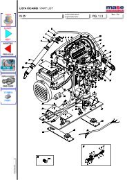
4.9.13) Starter<br />
4.9.13)Motorino avviamento<br />
Caratteristiche:12V 0,8 KW<br />
Fig. 23<br />
Characteristics:12V 0,8 KW<br />
Testing method:<br />
-Disconnect the wires.<br />
-Connect a 12V battery (+)pole with the screw<br />
clamp and (-) pole to the body <strong>of</strong> the starter<br />
(Fig.24).<br />
-Connect the screw clamp and the adiacent faston<br />
and verify if the starter is running well<br />
(Fig.24 Ref.1).<br />
Metodo di controllo:<br />
-Scollegare i cavi.<br />
-Utilizzare una batteria 12V collegando il (+)<br />
della batteria con il morsetto a vite ed il (-) a<br />
massa (carcassa del motorino)(Fig.24).<br />
-Verificare che il motorino giri facendo un<br />
ponte fra il morsetto a vite (+ motorino avviamento)<br />
ed il fast-on adiacente(Fig.24 Rif.1).<br />
1<br />
Fig.24<br />
24
4.91.4) Cinghia pompa acqua<br />
4.9.14) Water pump belt<br />
Caratteristiche - Characteristics:<br />
IS 2500 50 Hz Z21½ - 10x545<br />
60 Hz Z22<br />
- 10x560<br />
IS 3500/1 50 Hz Z23<br />
- 10x585<br />
60 Hz Z24<br />
- 10x610<br />
IS 4500/1 50 Hz Z24<br />
- 10x610<br />
IS 5500/1 60 Hz Z25<br />
- 10x635<br />
Metodo di controllo:<br />
-Premere con circa 10Kg sulla cinghia, verificare<br />
che la flessione non superi 0,5cm (Fig.25).<br />
RIMEDIO: Tendere la cinghia, allentare i bulloni<br />
di fissaggio pompa acqua (Fig.26 Rif1).<br />
Agire sulla vite di regolazione (Fig.26 Rif.2) e<br />
serrare i bulloni di fissaggio (Fig.26 Rif1).<br />
Testing method:<br />
-Press the belt with about 10Kg and be sure that<br />
bending is not superior to 0,5 cm (Fig.25).<br />
REMEDY: Stretch the belt. Slacken the fixing<br />
bolts <strong>of</strong> the water pump (Fig.26 Ref.1).<br />
Adjust the screw (Fig.26 Rif.2) and tighten the<br />
fixing bolts (Fig.26 Rif1).<br />
N.B. For a correct functioning <strong>of</strong> the water<br />
pump repete these operations every 200<br />
hours'period.<br />
N.B.per un corretto funzionamento della pompa<br />
acqua eseguire queste operazioni ogni 200<br />
ore.<br />
Fig.26<br />
Fig.25<br />
25
4.9.15) Pompa acqua<br />
4.9.15) Water pump<br />
Caratteristiche:diametro 40mm<br />
altezza 20mm<br />
type Johnson (F35 B/8)<br />
Metodo di controllo:<br />
-Visivo<br />
-Togliere le viti Fig.27 Rif.1 e rimuovere il<br />
coperchio pompa Fig.27 Rif.2.<br />
-Rimuovere la girante (Fig.27 Rif.3).<br />
RIMEDIO: Sostituire la girante<br />
N.B.Per un corretto funzionamento del gruppo<br />
e' necessario eseguire questa verifica ogni 300<br />
ore oppure dopo un anno.<br />
Characteristics: diameter 40mm<br />
height 20mm<br />
type Johnson (F35 B/8)<br />
Testing method:<br />
-Visual<br />
-Remove the screws (Fig.27 Ref1) and pump<br />
cover (Fig.27 Ref.2).<br />
-Remove the impeller (Fig.27 Ref.3).<br />
REMEDY: Remove the impeller<br />
N.B. For a correct functioning <strong>of</strong> the generator<br />
repete these operations every 300 hours' period<br />
or after a year's time <strong>of</strong> use.<br />
Fig.27<br />
26
4.9.16)Regolazione dei giri<br />
Caratteristiche:<br />
4.9.16)Engine speed adjustment<br />
Characteristics:<br />
50Hz<br />
vuoto<br />
52/52.5 Hz 225/230V-110/115V<br />
50Hz<br />
no load<br />
52/52.5 Hz 225/230V-110/115V<br />
carico<br />
50/51 Hz 215/220V-105/110V<br />
full load 50/51 Hz 215/220V-105/110V<br />
60Hz<br />
vuoto<br />
62/62.5 Hz 245/250V-120/125V<br />
60Hz<br />
no load<br />
62/62.5 Hz 245/250V-120/125V<br />
carico<br />
60/56 Hz 235/240V-115/120V<br />
full load<br />
60/56 Hz 235/240V-115/120V<br />
Poiche' gli alternatori MASE sono del tipo a due<br />
poli vale la corrispondenza 1Hz-> 60 giri/<br />
min.(3000 giri/min.->50Hz 3600 giri/min.-<br />
>60Hz).<br />
Metodo di controllo:<br />
-Verificare la frequenza all'uscita dei morsetti di<br />
potenza con uno strumento idoneo (frequenzimetro<br />
a lamelle o digitale).<br />
Per una lettura corretta dei valori<br />
di tensione ed amperaggio<br />
utilizzare solo strumenti a vero<br />
valore efficace<br />
(R.S.M.)<br />
RIMEDIO: Allentare la vite (Fig.28 Rif 1/2).<br />
-Ruotare le staffe sino al raggiungimento del n°<br />
dei giri quindi bloccare le viti.<br />
N.B.Poiche' la tensione generata dal gruppo e'<br />
proporzionale alla frequenza,verificare il numero<br />
dei giri del motore quale possibile causa di<br />
anomalie di tensione.<br />
IMPORTANTE:<br />
Poiche' la taratura del numero di<br />
giri del motore viene eseguita e<br />
quindi bloccata in sede di collaudo<br />
si consiglia in generale di<br />
intervenire sulla stessa.<br />
La indicazioni date qui sono riferite<br />
ad interventi di prima necessità a<br />
cui dovrà far seguito un controllo<br />
del motore. A titolo indicativo fra<br />
le possibili cause di basso<br />
rendimento del motore si consiglia<br />
di verificare l'eventualita' di filtro<br />
aria o filtro nafta intasati, iniettori<br />
difettoso od otturato.<br />
Since the alternator is a two pole type, 1Hz->60<br />
R.P.M. (3000 R.P.M. ->50Hz 3600 R.P.M. -><br />
60Hz).<br />
Testing method:<br />
-Verify the frequency at power terminals using<br />
a suitable instrument (vibrating-reed or digital<br />
frequency-meter).<br />
Correct readings <strong>of</strong> voltage and<br />
amperage are abtained only by<br />
employing instruments with true<br />
effective value<br />
REMEDY: Slack the screw (Fig.28 Rif 1/2).<br />
-Rotate the levers up to reach RPM then block<br />
the screws.<br />
N.B.Since voltage is proportional to the<br />
frequency, if and when there is voltage anomalies<br />
check the RPM.<br />
IMPORTANTE:<br />
Since RPM is adjusted and blocked<br />
during the testing phase,it's<br />
advisable not to modify it.The<br />
above instruction should be<br />
followed by a check-up <strong>of</strong> the<br />
engine. For your informations when<br />
looking for causes leading to low<br />
efficency, it is advisable to verify<br />
air filter, fuel filter choking,<br />
defective holed injection.<br />
Fig.28<br />
27
5)TABELLA GUASTI<br />
5)TROUBLE SHOOTING<br />
COMPLAINT<br />
PROBABLE REASON<br />
DOES NOT<br />
START<br />
START AND<br />
STOP<br />
UNSTABLE<br />
RUNNING<br />
WHITE SMOCKE<br />
BLACK SMOCKE<br />
Defective starting buttons<br />
l<br />
Defective fuel solenoid l l<br />
Defective battery Battery<br />
cable section<br />
l<br />
Defective starting motor<br />
l<br />
Piping fuel filter choked l l<br />
12V circuit fuse<br />
l<br />
Avv./Ev.relay<br />
l<br />
Too much oil in crankcase l l<br />
Safety device intervention l l<br />
Overload<br />
l<br />
Defective governor linkage<br />
l<br />
Worm valve guides<br />
l<br />
Blocked valves<br />
l<br />
Worm cylinder and position rings<br />
l<br />
Defective injector l l<br />
Defective injector pump l l l l<br />
Defective feeding pump<br />
l l<br />
28
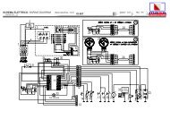
6)SCHEMA ELETTRICO<br />
6)WIRING DIAGRAM<br />
6<br />
DESCRIZIONE<br />
1 ROTORE<br />
2 STATORE<br />
3 DIODO 3A<br />
4 VARISTORE<br />
5 SCHEDA RELAY<br />
6 MORSETTIERA DI POTENZA<br />
7 MORSETTIERA CIRCUITO RELAY<br />
8 MOSETTIERA PANNELLO COMANDI<br />
9 FUSIBILE 1A<br />
10 CONDENSATORE<br />
11 REGOLATORE CARICA BATTERIA<br />
12 FUSIBILE<br />
13 MOTORINO AVVIAMENTO<br />
14 BATTERIA<br />
15 POMPA COMBUSTIBILE<br />
16 ELETTROVALVOLA STOP<br />
17 PRESSOSTATO OLIO<br />
18 TERMOSTATO TESTATA MOTORE<br />
19 TERMOSTATO ACQUA<br />
20 TERMOSTATO ALTERNATORE<br />
DESCRIPTION<br />
1 ROTOR<br />
2 STATOR<br />
3 DIODE 3A<br />
4 VARISTOR<br />
5 PRINTED CIRCUIT RELAY<br />
6 POWER TERMINAL BOARD<br />
7 RELAY CIRCUIT TERMINAL BOARD<br />
8 CONTROL PANEL TERMINAL BOARD<br />
9 FUSE 1A<br />
10 CAPACITOR<br />
11 BATTERY CHARGER REGULATOR<br />
12 FUSE<br />
13 STARTER<br />
14 BATTERY<br />
15 FUEL PUMP<br />
16 FUEL SOLENOID<br />
17 OIL PRESSURE SWITCH<br />
18 OVERHEAD ENGINE THERMOSTAT<br />
19 WATER TERMOSTAT<br />
20 ALTERNATOR THERMOSTAT<br />
29