Vitosolic 100 SD1 Installation905 KB - Viessmann
Vitosolic 100 SD1 Installation905 KB - Viessmann
Vitosolic 100 SD1 Installation905 KB - Viessmann

You also want an ePaper? Increase the reach of your titles
YUMPU automatically turns print PDFs into web optimized ePapers that Google loves.
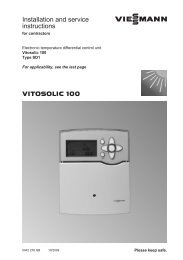
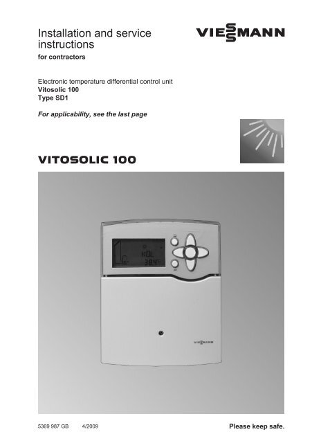
Installation and service<br />
instructions<br />
for contractors<br />
VIESMANN<br />
Electronic temperature differential control unit<br />
<strong>Vitosolic</strong> <strong>100</strong><br />
Type <strong>SD1</strong><br />
For applicability, see the last page<br />
VITOSOLIC <strong>100</strong><br />
5369 987 GB 4/2009 Please keep safe.
Safety instructions<br />
Safety instructions<br />
Please follow these safety instructions closely to prevent accidents and material<br />
losses.<br />
Safety instructions explained<br />
Danger<br />
This symbol warns against the<br />
risk of injury.<br />
!<br />
Please note<br />
This symbol warns against the<br />
risk of material losses and environmental<br />
pollution.<br />
Note<br />
Details identified by the word "Note" contain<br />
additional information.<br />
Target group<br />
These instructions are exclusively<br />
designed for qualified personnel.<br />
■ Work on electrical equipment must<br />
only be carried out by a qualified electrician.<br />
■ The system must be commissioned by<br />
the system installer or a qualified person<br />
authorised by the installer.<br />
Regulations<br />
Working on the system<br />
■ Isolate the system from the power supply<br />
and check that it is no longer 'live',<br />
e.g. by removing a separate fuse or by<br />
means of a main isolator.<br />
■ Safeguard the system against unauthorised<br />
reconnection.<br />
Please note<br />
! Electronic modules can be damaged<br />
by electrostatic discharges.<br />
Touch earthed objects, such as<br />
heating or water pipes, to discharge<br />
static loads.<br />
Repair work<br />
!<br />
Please note<br />
Repairing components that fulfil a<br />
safety function can compromise<br />
the safe operation of your heating<br />
system.<br />
Replace faulty components only<br />
with original <strong>Viessmann</strong> spare<br />
parts.<br />
Observe the following when working on<br />
this system<br />
■ all legal instructions regarding the prevention<br />
of accidents,<br />
■ all legal instructions regarding environmental<br />
protection,<br />
■ the Code of Practice of relevant trade<br />
associations.<br />
■ all current safety regulations as<br />
defined by DIN, EN, DVGW, VDE and<br />
all locally applicable standards<br />
5369 987 GB<br />
2
Safety instructions<br />
Safety instructions (cont.)<br />
Ancillary components, spare and<br />
wearing parts<br />
Please note<br />
! Spare and wearing parts that<br />
have not been tested together<br />
with the heating system can compromise<br />
its function. Installing<br />
non-authorised components and<br />
non-approved modifications or<br />
conversions can compromise<br />
safety and may invalidate our<br />
warranty.<br />
For replacements, use only original<br />
spare parts supplied or<br />
approved by <strong>Viessmann</strong>.<br />
5369 987 GB<br />
3
Index<br />
Installation instructions<br />
Preparing for installation<br />
Installation information......................................................................................... 6<br />
System example 1................................................................................................ 6<br />
System example 2................................................................................................ 11<br />
System example 3................................................................................................ 18<br />
System example 4................................................................................................ 24<br />
Installation sequence<br />
Fitting the solar control unit.................................................................................. 35<br />
Overview of electrical connections....................................................................... 36<br />
Solar circuit pump................................................................................................. 36<br />
Pump/valve at output R2...................................................................................... 38<br />
High limit safety cut-out........................................................................................ 39<br />
Collector temperature sensor............................................................................... 40<br />
Cylinder temperature sensor................................................................................ 41<br />
Temperature sensor............................................................................................. 41<br />
Power supply........................................................................................................ 42<br />
Service instructions<br />
Commissioning<br />
Switching the power ON....................................................................................... 44<br />
Navigation through the menu............................................................................... 44<br />
Selecting the system scheme............................................................................... 44<br />
Setting system parameters................................................................................... 45<br />
Resetting system parameters............................................................................... 45<br />
Carrying out a relay test....................................................................................... 45<br />
Service scans<br />
Scanning temperatures and operating conditions................................................ 46<br />
Troubleshooting<br />
Fault messages.................................................................................................... 47<br />
Checking sensors................................................................................................. 47<br />
Changing the fuse................................................................................................ 48<br />
Function description<br />
Parameter overview............................................................................................. 49<br />
System scheme.................................................................................................... 51<br />
Collector limit temperature................................................................................... 62<br />
Collector cooling function..................................................................................... 62<br />
Minimum collector temperature limit..................................................................... 62<br />
4<br />
Index<br />
5369 987 GB
Index<br />
Index (cont.)<br />
Frost protection function....................................................................................... 63<br />
Reverse cooling function...................................................................................... 63<br />
Interval function.................................................................................................... 63<br />
Heat statement..................................................................................................... 64<br />
Speed control....................................................................................................... 64<br />
Parts list.............................................................................................................. 66<br />
Specification....................................................................................................... 67<br />
Appendix............................................................................................................. 68<br />
Certificates<br />
Declaration of conformity...................................................................................... 69<br />
Keyword index.................................................................................................... 70<br />
5369 987 GB<br />
5
Preparing for installation<br />
Installation information<br />
Danger<br />
Subject to system configuration,<br />
DHW temperatures above 60 °C<br />
can occur. DHW with temperatures<br />
in excess of 60 °C can result<br />
in scalding.<br />
To limit the temperature to 60 °C,<br />
install mixing equipment, e.g. a<br />
thermostatically controlled mixing<br />
valve (accessory). Install a<br />
mixer tap as anti-scalding device<br />
at the draw-off point.<br />
System example 1<br />
DHW heating with dual-mode DHW cylinder<br />
Main components<br />
■ <strong>Viessmann</strong> solar collectors<br />
■ DHW cylinders Vitocell <strong>100</strong>-B or<br />
Vitocell 300-B<br />
■ <strong>Vitosolic</strong> <strong>100</strong>, type <strong>SD1</strong><br />
■ Solar-Divicon<br />
■ Wall mounted oil/gas boiler or oil/gas<br />
boiler<br />
Function description<br />
DHW heating with solar energy<br />
Solar circuit pump R1 eE starts and<br />
DHW cylinder qP is heated up if the temperature<br />
differential between collector<br />
temperature sensor S1 eQ and cylinder<br />
temperature sensor S2 qQ exceeds the<br />
starting temperature differential DT E.<br />
Solar circuit pump R1 eE is stopped in<br />
accordance with the following criteria:<br />
■ The actual temperature falls below the<br />
shutdown temperature differential<br />
DT A.<br />
■ Exceeding the electronic temperature<br />
limit (max. 90°C) of control unit eZ<br />
■ Reaching the temperature selected at<br />
high limit safety cut-out qW (if installed)<br />
Auxiliary function for DHW heating<br />
The requirements for the auxiliary function<br />
are achieved through circulation<br />
pump R2 qT.<br />
Suppression of DHW cylinder reheating<br />
by the boiler<br />
Coding address "67" in boiler control unit<br />
2 defaults a third set DHW temperature<br />
(setting range 10 to 95 °C). This value<br />
must be below the first set DHW temperature.<br />
DHW cylinder qP will only be<br />
heated by boiler 1 (solar circuit<br />
pump R1 eE runs) if this set value cannot<br />
be achieved by the solar thermal system.<br />
DHW heating without solar energy<br />
The upper section of DHW cylinder qP is<br />
heated by boiler 1. The cylinder thermostat<br />
with cylinder temperature sensor<br />
3 of boiler control unit 2 regulates<br />
cylinder heating.<br />
5369 987 GB<br />
6
Preparing for installation<br />
System example 1 (cont.)<br />
Required settings on the solar control unit<br />
Param Delivered Description<br />
Setting<br />
eters condition<br />
ANL 1 Without auxiliary function for DHW heating 1<br />
With auxiliary function for DHW heating (see<br />
4<br />
page 56)<br />
DT E 8 K Start temperature differential for solar circuit pump<br />
at R1<br />
DT A 4 K Stop temperature differential for solar circuit pump<br />
at R1<br />
S SL 60 °C Set cylinder temperature (see page 53)<br />
For further functions, see chapter "Functions" from page 49.<br />
Note<br />
"DT E" can be set at least 0.5 K higher<br />
than "DT A".<br />
"DT A" can be set up to 0.5 K below<br />
"DT E".<br />
Information regarding speed control<br />
of the solar circuit pump<br />
Observe chapter "Speed control" (see<br />
page 64).<br />
5369 987 GB<br />
Installation<br />
7
Preparing for installation<br />
System example 1 (cont.)<br />
Hydraulic installation diagram<br />
5369 987 GB<br />
eQ<br />
eW<br />
eE<br />
N<br />
eP<br />
qR<br />
qT<br />
eZ<br />
qW<br />
qP<br />
qE<br />
3<br />
qQ<br />
2<br />
1<br />
4<br />
2<br />
1<br />
M<br />
8
Preparing for installation<br />
System example 1 (cont.)<br />
Equipment required<br />
Pos. Description<br />
1 Oil/gas boiler or wall mounted oil/gas boiler<br />
with<br />
2 Boiler and heating circuit control unit<br />
3 Cylinder temperature sensor<br />
4 Circulation pump for cylinder heating<br />
(integrated for wall mounted oil/gas boiler)<br />
qP Dual-mode DHW cylinder<br />
qQ Cylinder temperature sensor S2<br />
qW High limit safety cut-out (accessory)<br />
qE DHW circulation pump (on site)<br />
(internal/external extension may be required for connecting a wall mounted<br />
oil/gas boiler)<br />
qR Thermostatic mixing valve (accessory)<br />
qT Circulation pump R2 (anti-stratification) (on site)<br />
eP Solar collectors<br />
eQ Collector temperature sensor S1<br />
eW Solar-Divicon (accessory)<br />
with<br />
eE Solar circuit pump R1<br />
eZ <strong>Vitosolic</strong> <strong>100</strong>, type <strong>SD1</strong><br />
eU Junction box (on site)<br />
eI ON/OFF switch (on site)<br />
5369 987 GB<br />
Installation<br />
9
Preparing for installation<br />
System example 1 (cont.)<br />
Electrical installation diagram<br />
eZ<br />
eI<br />
230 V / 50 Hz<br />
<br />
21<br />
20<br />
15<br />
19<br />
18<br />
14<br />
eU<br />
230 V / 50 Hz<br />
M<br />
1~ R1<br />
eE<br />
High limit qW safety cut-out<br />
17<br />
16<br />
13<br />
M<br />
1~<br />
R2<br />
qT<br />
145<br />
12<br />
11<br />
KM BUS 2<br />
Low voltage<br />
10<br />
9<br />
6<br />
5<br />
4<br />
3<br />
SOL<br />
qQ<br />
2<br />
1<br />
KOL<br />
eQ<br />
5369 987 GB<br />
10
Preparing for installation<br />
System example 2<br />
Vitodens – DHW heating and central heating backup with a multimode<br />
heating water buffer cylinder<br />
5369 987 GB<br />
Main components<br />
■ <strong>Viessmann</strong> solar collectors<br />
■ Vitocell 340-M or Vitocell 360-M multimode<br />
heating water buffer cylinder<br />
with integral DHW heating, with or<br />
without stratification system<br />
■ <strong>Vitosolic</strong> <strong>100</strong>, type <strong>SD1</strong><br />
■ Solar-Divicon<br />
■ Wall mounted gas boiler from the year<br />
of manufacture 2008<br />
– Vitodens 200-W, type WB2B<br />
– Vitodens 300-W, type WB3C<br />
Function description<br />
DHW heating with solar energy<br />
Solar circuit pump R1 eE starts and<br />
heating water buffer cylinder qP is<br />
heated up if the temperature differential<br />
between collector temperature sensor<br />
S1 eQ and cylinder temperature sensor<br />
S2 qQ exceeds the starting temperature<br />
differential DT E.<br />
Solar circuit pump R1 eE is stopped in<br />
accordance with the following criteria:<br />
■ The actual temperature falls below the<br />
shutdown temperature differential<br />
DT A.<br />
■ Exceeding the electronic temperature<br />
limit (max. 90°C) of control unit eZ<br />
■ Reaching the temperature selected at<br />
high limit safety cut-out qW (if installed)<br />
Entire heating water buffer cylinder qP is<br />
heated by the solar thermal system if the<br />
insolation is adequate.<br />
The upper part of heating water buffer<br />
cylinder qP will only be reheated by<br />
boiler 1 if the actual water temperature<br />
falls below the set temperature selected<br />
at boiler control unit 2.<br />
If the solar energy is inadequate to cover<br />
the entire heating demand, the DHW in<br />
the lower part of heating water buffer cylinder<br />
qP will be preheated by solar<br />
energy. The DHW in the upper part of the<br />
cylinder is heated to the required temperature<br />
by boiler 1.<br />
The burner is started and three-way<br />
diverter valve rZ is switched to position<br />
"AB-A" via cylinder temperature sensor<br />
qZ of the boiler control unit. When<br />
the set DHW temperature has been<br />
reached, the burner is stopped and<br />
three-way diverter valve rZ is switched<br />
to position "AB-B".<br />
Suppression of DHW cylinder reheating<br />
by the boiler<br />
Coding address "67" in boiler control<br />
unit 2 defaults a third set DHW temperature<br />
(setting range 10 to 95 °C). This<br />
value must be below the first set DHW<br />
temperature. Heating water buffer cylinder<br />
qP is only heated by boiler 1 (solar<br />
circuit pump R1 eE runs) if this set value<br />
cannot be achieved by the solar thermal<br />
system.<br />
11<br />
Installation
Preparing for installation<br />
System example 2 (cont.)<br />
DHW heating without solar energy<br />
The upper area of heating water buffer<br />
cylinderqP is heated by boiler 1. The<br />
integral instantaneous water heater/<br />
standby section is heated by the surrounding<br />
buffer cylinder water.<br />
The cylinder thermostat with cylinder<br />
temperature sensor qZ of boiler control<br />
unit 2 controls<br />
three-way diverter valve rZ.<br />
Central heating with solar energy<br />
Central heating without solar energy<br />
If the temperature at sensor qT is inadequate,<br />
the burner and circulation pump<br />
in the Vitodens are started. The area<br />
between HV2/HR1 and HR2 in heating<br />
water buffer cylinder qP is heated up to<br />
the set temperature for the heating circuits<br />
in weather-compensated mode.<br />
When this set temperature is exceeded,<br />
the burner and, after a delay, the circulation<br />
pump in the Vitodens are stopped.<br />
The system provides central heating if<br />
the temperature at sensor qT is adequate.<br />
Required settings on the solar control unit<br />
Param Delivered Description<br />
Setting<br />
eters condition<br />
ANL 1 Without auxiliary function for DHW heating 1<br />
DT E 8 K Start temperature differential for solar circuit pump<br />
at R1<br />
DT A 4 K Stop temperature differential for solar circuit pump<br />
at R1<br />
S SL 60 °C Set cylinder temperature (see page 53)<br />
For further functions, see chapter "Functions" from page 49.<br />
Note<br />
"DT E" can be set at least 0.5 K higher<br />
than "DT A".<br />
"DT A" can be set up to 0.5 K below<br />
"DT E".<br />
Information regarding speed control<br />
of the solar circuit pump<br />
Observe chapter "Speed control" (see<br />
page 64).<br />
5369 987 GB<br />
12
Preparing for installation<br />
System example 2 (cont.)<br />
Codes required at the boiler and heating circuit control unit<br />
Code<br />
Function<br />
51:1 The internal circulation pump is only switched on when the burner<br />
has been started (time delay off)<br />
53:3 System without DHW circulation pump:<br />
Three-way diverter valve rZ is connected to output sK of internal<br />
extension H1 or H2<br />
5b:1 Internal diverter valve without function<br />
(DHW cylinder connected downstream of the low loss header)<br />
5369 987 GB<br />
Installation<br />
13
Preparing for installation<br />
System example 2 (cont.)<br />
Hydraulic installation diagram<br />
5369 987 GB<br />
eQ<br />
eW<br />
eE<br />
N<br />
eP<br />
qW<br />
qZ<br />
qT<br />
qQ<br />
eZ<br />
qP<br />
qR<br />
HV1<br />
wW<br />
HV2/HR1<br />
HR2<br />
HR3<br />
qE<br />
5/28<br />
2<br />
M<br />
rZ<br />
5/21<br />
1<br />
M<br />
14
Preparing for installation<br />
System example 2 (cont.)<br />
Equipment required<br />
Pos. Description<br />
1 Wall mounted gas boiler<br />
with<br />
2 Boiler and heating circuit control unit<br />
3 Internal extension H1 (standard delivery for the Vitodens 300-W)<br />
or<br />
4 Internal extension H2 (accessory)<br />
or<br />
System with DHW circulation pump:<br />
5 External extension H1 (accessory)<br />
6 KM BUS distributor (accessory)<br />
qP Heating water buffer cylinder<br />
with<br />
wW Threaded DHW circulation pump (accessory)<br />
qT Temperature sensor (flow temperature sensor for low loss header; in this<br />
scheme with heating water buffer cylinder) (accessory)<br />
qZ Cylinder temperature sensor (accessory)<br />
qQ Cylinder temperature sensor S2<br />
qW High limit safety cut-out (accessory)<br />
qE DHW circulation pump (on site)<br />
qR Thermostatic mixing valve (accessory)<br />
eP Solar collectors<br />
eQ Collector temperature sensor S1<br />
eW Solar-Divicon (accessory)<br />
with<br />
eE Solar circuit pump R1<br />
eZ <strong>Vitosolic</strong> <strong>100</strong>, type <strong>SD1</strong><br />
eU Junction box (on site)<br />
eI ON/OFF switch (on site)<br />
rZ Three-way diverter valve (accessory)<br />
5369 987 GB<br />
Installation<br />
15
Preparing for installation<br />
System example 2 (cont.)<br />
Electrical installation diagram<br />
eZ<br />
eI<br />
230 V / 50 Hz<br />
<br />
21<br />
20<br />
15<br />
19<br />
18<br />
14<br />
17<br />
16<br />
13<br />
eU<br />
230 V / 50 Hz<br />
M<br />
1~ R1<br />
eE<br />
High limit qW safety cut-out<br />
145<br />
12<br />
11<br />
A<br />
Low voltage<br />
10<br />
9<br />
6<br />
5<br />
4<br />
3<br />
SOL<br />
qQ<br />
2<br />
1<br />
KOL<br />
eQ<br />
5369 987 GB<br />
16
Preparing for installation<br />
System example 2 (cont.)<br />
2<br />
fÖ<br />
L<br />
<br />
230 V / 50 Hz<br />
3 4<br />
lH lH<br />
5<br />
230 V / 50 Hz<br />
lH<br />
<br />
1<br />
gD<br />
sK<br />
<br />
aBJ<br />
sK <br />
<br />
fÖ<br />
sÖ<br />
sA <br />
sK <br />
gÖ<br />
<br />
M<br />
1~<br />
rZ<br />
M<br />
1~ ZP qE<br />
Installation<br />
aVG 2 1<br />
Low voltage<br />
% STS qZ<br />
4<br />
5<br />
6<br />
7<br />
6<br />
qT<br />
aVG<br />
2<br />
1 2<br />
aVG<br />
aVG<br />
1<br />
2<br />
1<br />
2<br />
A<br />
5369 987 GB<br />
17
Preparing for installation<br />
System example 3<br />
Vitodens – DHW heating with freshwater module and central<br />
heating backup with heating water buffer cylinder<br />
Main components<br />
■ <strong>Viessmann</strong> solar collectors<br />
■ Freshwater module<br />
■ Heating water buffer cylinder<br />
Vitocell140-E or Vitocell 160-E<br />
■ <strong>Vitosolic</strong> <strong>100</strong>, type <strong>SD1</strong><br />
■ Solar-Divicon<br />
■ Wall mounted gas boiler from the year<br />
of manufacture 2008<br />
– Vitodens 200-W, type WB2B<br />
– Vitodens 300-W, type WB3C<br />
Function description<br />
Freshwater module qP heats DHW<br />
when hot water is drawn. The energy<br />
supply to freshwater module qP is provided<br />
via heating water buffer cylinder<br />
rP.<br />
DHW heating with solar energy<br />
Solar circuit pump R1 eE starts and<br />
heating water buffer cylinder rP is<br />
heated up if the temperature differential<br />
between collector temperature sensor<br />
S1 eQ and cylinder temperature sensor<br />
S2 rQ exceeds the start temperature differential<br />
DT E.<br />
Solar circuit pump R1 eE is stopped in<br />
accordance with the following criteria:<br />
■ The actual temperature falls below the<br />
shutdown temperature differential<br />
DT A.<br />
■ Exceeding the electronic temperature<br />
limit (max. 90°C) of control unit eZ<br />
■ Reaching the temperature selected at<br />
high limit safety cut-out rR (if installed)<br />
Entire heating water buffer cylinder rP is<br />
heated by the solar thermal system if the<br />
insolation is adequate.<br />
The upper part of heating water buffer<br />
cylinder rP will only be reheated by<br />
boiler 1 if the actual water temperature<br />
falls below the set temperature selected<br />
at boiler control unit 2.<br />
The burner is started and three-way<br />
diverter valve rZ is switched to position<br />
"AB-A" via cylinder temperature sensor<br />
rW of the boiler control unit. When<br />
the set DHW temperature has been<br />
reached, the burner is stopped and<br />
three-way diverter valve rZ is switched<br />
to position "AB-B".<br />
Suppression of DHW cylinder reheating<br />
by the boiler<br />
Coding address "67" in boiler control<br />
unit 2 defaults a third set DHW temperature<br />
(setting range 10 to 95 °C). This<br />
value must be below the first set DHW<br />
temperature. Heating water buffer cylinder<br />
rP is only heated by the boiler (solar<br />
circuit pump R1 eE runs) if this set value<br />
cannot be achieved by the solar thermal<br />
system.<br />
DHW heating without solar energy<br />
The upper area of heating water buffer<br />
cylinder rP is heated by boiler 1.<br />
The cylinder thermostat with cylinder<br />
temperature sensor rW of boiler control<br />
unit 2 controls<br />
three-way diverter valve rZ.<br />
5369 987 GB<br />
18
Preparing for installation<br />
System example 3 (cont.)<br />
Central heating with solar energy<br />
Central heating without solar energy<br />
Central heating is provided via heating<br />
water buffer cylinder rP if the temperature<br />
at sensor rE is adequate.<br />
Required settings on the solar control unit<br />
If the temperature at sensor rE is inadequate,<br />
the burner and circulation pump<br />
in the Vitodens are started. The area<br />
between HV3/HR1 and HR3 in heating<br />
water buffer cylinder rP is heated up to<br />
the set temperature for the heating circuits<br />
in weather-compensated mode.<br />
When this set temperature is exceeded,<br />
the burner and, after a delay, the circulation<br />
pump in the Vitodens are stopped.<br />
Installation<br />
Param Delivered Description<br />
Setting<br />
eters condition<br />
ANL 1 Without auxiliary function for DHW heating 1<br />
DT E 8 K Start temperature differential for solar circuit pump<br />
at R1<br />
DT A 4 K Stop temperature differential for solar circuit pump<br />
at R1<br />
S SL 60 °C Set cylinder temperature (see page 53)<br />
For further functions, see chapter "Functions" from page 49.<br />
Note<br />
"DT E" can be set at least 0.5 K higher<br />
than "DT A".<br />
"DT A" can be set up to 0.5 K below<br />
"DT E".<br />
Information regarding speed control<br />
of the solar circuit pump<br />
Observe chapter "Speed control" (see<br />
page 64).<br />
5369 987 GB<br />
Codes required at the boiler and heating circuit control unit<br />
Code<br />
Function<br />
51:1 The internal circulation pump is only switched on when the<br />
burner has been started (time delay off)<br />
53:3 System without DHW circulation pump:<br />
Three-way diverter valve rZ is connected to output sK of internal<br />
extension H1 or H2<br />
5b:1 Internal diverter valve without function<br />
(DHW cylinder connected downstream of the low loss header)<br />
19
Preparing for installation<br />
System example 3 (cont.)<br />
Hydraulic installation diagram<br />
5369 987 GB<br />
eQ<br />
eW<br />
eE<br />
rR<br />
rW<br />
rE<br />
rQ<br />
qE<br />
N<br />
eP<br />
rP<br />
eZ<br />
HV1<br />
HV2<br />
HV3/HR1<br />
HR2<br />
HR3<br />
HR4<br />
qQ<br />
M<br />
qW<br />
qP<br />
rZ<br />
M<br />
M<br />
2<br />
1<br />
20
Preparing for installation<br />
System example 3 (cont.)<br />
Equipment required<br />
Pos. Description<br />
1 Wall mounted gas boiler<br />
with<br />
2 Boiler and heating circuit control unit<br />
rW Cylinder temperature sensor STS<br />
3 Internal extension H1 (standard delivery for the Vitodens 300-W)<br />
or<br />
4 Internal extension H2 (accessory)<br />
qP Freshwater module<br />
with<br />
qQ Three-way diverter valve R3<br />
and<br />
qW Temperature sensor S4<br />
and<br />
qE Temperature sensor S3<br />
qR ON/OFF switch (on site)<br />
rP Heating water buffer cylinder<br />
rQ Cylinder temperature sensor S2<br />
rR High limit safety cut-out (accessory)<br />
eP Solar collectors<br />
eQ Collector temperature sensor S1<br />
eW Solar-Divicon (accessory)<br />
with<br />
eE Solar circuit pump R1<br />
eZ <strong>Vitosolic</strong> <strong>100</strong>, type <strong>SD1</strong><br />
eU Junction box (on site)<br />
eI ON/OFF switch (on site)<br />
rE Temperature sensor (flow temperature sensor for low loss header) (accessory)<br />
rZ Three-way diverter valve (accessory)<br />
5369 987 GB<br />
Installation<br />
21
Preparing for installation<br />
System example 3 (cont.)<br />
Electrical installation diagram<br />
eZ<br />
eI<br />
230 V / 50 Hz<br />
<br />
21<br />
20<br />
15<br />
19<br />
18<br />
14<br />
17<br />
16<br />
13<br />
eU<br />
230 V / 50 Hz<br />
M<br />
1~ R1<br />
eE<br />
High limit rR safety cut-out<br />
145<br />
12<br />
11<br />
A<br />
Low voltage<br />
10<br />
9<br />
6<br />
5<br />
4<br />
3<br />
SOL<br />
rQ<br />
2<br />
1<br />
KOL<br />
eQ<br />
5369 987 GB<br />
22
Preparing for installation<br />
System example 3 (cont.)<br />
2<br />
fÖ<br />
L<br />
<br />
230 V / 50 Hz<br />
3 4<br />
lH<br />
lH<br />
230 V / 50 Hz<br />
lH<br />
<br />
1<br />
gD<br />
sK<br />
<br />
aBJ<br />
sK<br />
<br />
M<br />
1~<br />
rZ<br />
Installation<br />
Low voltage<br />
% STS rW<br />
4<br />
5<br />
6<br />
7<br />
A<br />
rE<br />
5369 987 GB<br />
23
Preparing for installation<br />
System example 3 (cont.)<br />
Control unit, freshwater module<br />
qP<br />
qR<br />
230 V / 50 Hz<br />
<br />
<br />
230 V / 50 Hz<br />
M<br />
1~ R3<br />
qQ<br />
Low voltage<br />
S4<br />
S3<br />
qW<br />
qE<br />
System example 4<br />
DHW heating with solar retrofit system<br />
There are two control versions for this<br />
system example:<br />
■ Anti-stratification with sensor S3 in<br />
DHW cylinder 2 (existing)<br />
■ Anti-stratification with sensor S3 in<br />
DHW cylinder 1 (retrofit)<br />
Anti-stratification with sensor S3 in DHW cylinder 2 (existing)<br />
Main components<br />
■ <strong>Viessmann</strong> solar collectors<br />
■ Mono-mode DHW cylinder (existing)<br />
■ Solar retrofit system with the following<br />
components:<br />
– Solar-Divicon<br />
– <strong>Vitosolic</strong> <strong>100</strong>, type <strong>SD1</strong><br />
– DHW cylinder Vitocell <strong>100</strong>-W, type<br />
CUG<br />
■ Wall mounted oil/gas boiler or oil/gas<br />
boiler (existing)<br />
5369 987 GB<br />
24
Preparing for installation<br />
System example 4 (cont.)<br />
Function description<br />
DHW heating with solar energy<br />
Solar circuit pump R1 qP starts and<br />
DHW cylinder qP is heated up if the temperature<br />
differential between collector<br />
temperature sensor S1 eE and cylinder<br />
temperature sensor S2 qQ exceeds the<br />
start temperature differential DT E.<br />
Solar circuit pump R1 eE is stopped in<br />
accordance with the following criteria:<br />
■ The actual temperature falls below the<br />
shutdown temperature differential<br />
DT A.<br />
■ Exceeding the electronic temperature<br />
limit (max. 90°C) of control unit eZ<br />
■ Reaching the temperature selected at<br />
high limit safety cut-out qW (if installed)<br />
Anti-stratification pump R2 qT starts if<br />
the temperature differential between<br />
sensor S2 qQ and sensor S3 qU<br />
exceeds the start temperature differential<br />
DT 3E. The water heated in DHW<br />
cylinder qP is transferred to DHW cylinder<br />
2 qI.<br />
The anti-stratification pump R2 will also<br />
start if there is a demand for DHW heating<br />
issued by the auxiliary function.<br />
Anti-stratification pump R2 qT stops in<br />
accordance with the following criteria:<br />
■ The actual temperature falls below the<br />
shutdown temperature differential<br />
DT 3A<br />
■ When the auxiliary function for DHW<br />
heating ends<br />
DHW circulation pump qE (if installed)<br />
for DHW cylinder 2 qI is controlled by<br />
boiler control unit 2.<br />
Suppression of DHW cylinder reheating<br />
by the boiler<br />
Coding address "67" in boiler control unit<br />
2 defaults a third set DHW temperature<br />
(setting range 10 to 95 °C). This value<br />
must be below the first set DHW temperature.<br />
DHW cylinder 2 qI will only be<br />
heated by boiler 1 (solar circuit<br />
pump R1 eE runs) if this set value cannot<br />
be achieved by the solar thermal system.<br />
DHW heating without solar energy<br />
DHW cylinder 2 qI is heated by boiler<br />
1. The cylinder thermostat with cylinder<br />
temperature sensor 3 of boiler control<br />
unit 2 regulates cylinder heating.<br />
Installation<br />
5369 987 GB<br />
Required settings on the solar control unit<br />
Param<br />
eters<br />
Delivered<br />
condition<br />
Description<br />
ANL 1 With auxiliary function for DHW heating (see<br />
page 56)<br />
DT E 8 K Start temperature differential for solar circuit pump<br />
at R1<br />
DT A 4 K Stop temperature differential for solar circuit pump<br />
at R1<br />
Setting<br />
8<br />
25
Preparing for installation<br />
System example 4 (cont.)<br />
Param<br />
eters<br />
Delivered<br />
condition<br />
Description<br />
DT 3E 8 K Start temperature differential for anti-stratification<br />
pump at R2<br />
DT 3A 4 K Stop temperature differential for anti-stratification<br />
pump at R2<br />
S SL 60 °C Set cylinder temperature (see page 53)<br />
For further functions, see chapter "Functions" from page 49.<br />
Setting<br />
Note<br />
"DT E/DT 3E" can be set to<br />
at least 0.5 K above "DT A/DT 3A".<br />
"DT A/DT 3A" can be set up to 0.5 K<br />
below "DT E/DT 3E".<br />
Information regarding speed control<br />
of the solar circuit pump<br />
Observe chapter "Speed control" (see<br />
page 64).<br />
5369 987 GB<br />
26
Preparing for installation<br />
System example 4 (cont.)<br />
Hydraulic installation diagram<br />
5369 987 GB<br />
eZ<br />
eQ<br />
eP<br />
eW<br />
P<br />
qE<br />
2<br />
eE<br />
qR<br />
1<br />
qT<br />
qW 2<br />
4<br />
qU<br />
1<br />
3<br />
2<br />
qQ<br />
qP<br />
qI<br />
Installation<br />
1<br />
M<br />
27
Preparing for installation<br />
System example 4 (cont.)<br />
Equipment required<br />
Pos. Description<br />
1 Oil/gas boiler or wall mounted oil/gas boiler<br />
with<br />
2 Boiler and heating circuit control unit<br />
3 Cylinder temperature sensor<br />
4 Circulation pump for cylinder heating<br />
(integrated for wall mounted oil/gas boiler)<br />
qI DHW cylinder 2, mono-mode (existing)<br />
qP DHW cylinder 1, mono-mode (solar retrofit system)<br />
qQ Cylinder temperature sensor S2<br />
qW High limit safety cut-out (accessory)<br />
qE DHW circulation pump (on site)<br />
(internal/external extension may be required for connecting a wall mounted<br />
oil/gas boiler)<br />
qR Thermostatic mixing valve (accessory)<br />
eP Solar collectors<br />
eQ Collector temperature sensor S1<br />
eW Solar-Divicon (solar retrofit system)<br />
with<br />
eE Solar circuit pump R1<br />
and<br />
eZ <strong>Vitosolic</strong> <strong>100</strong>, type <strong>SD1</strong><br />
eU Junction box (on site)<br />
eI ON/OFF switch (on site)<br />
DHW circulation diversion<br />
qT Circulation pump R2 (anti-stratification) (accessory)<br />
qU Temperature sensor S3 (DHW cylinder 2) (accessory)<br />
5369 987 GB<br />
28
Preparing for installation<br />
System example 4 (cont.)<br />
Electrical installation diagram<br />
eZ<br />
eI<br />
230 V / 50 Hz<br />
<br />
21<br />
20<br />
15<br />
19<br />
18<br />
14<br />
17<br />
16<br />
13<br />
eU<br />
230 V / 50 Hz<br />
M<br />
1~ R1<br />
M<br />
1~<br />
eE<br />
High limit qW safety cut-out<br />
R2<br />
qT<br />
Installation<br />
145<br />
12<br />
11<br />
KM BUS 2<br />
Low voltage<br />
10<br />
9<br />
6<br />
5<br />
4<br />
qU<br />
3<br />
SOL<br />
qQ<br />
2<br />
1<br />
KOL<br />
eQ<br />
Anti-stratification with sensor S3 in DHW cylinder 1 (retrofit)<br />
5369 987 GB<br />
Main components<br />
■ <strong>Viessmann</strong> solar collectors<br />
■ Mono-mode DHW cylinder (existing)<br />
■ Solar retrofit system with the following<br />
components:<br />
29
Preparing for installation<br />
System example 4 (cont.)<br />
– Solar-Divicon<br />
– <strong>Vitosolic</strong> <strong>100</strong>, type <strong>SD1</strong><br />
– DHW cylinder Vitocell <strong>100</strong>-W, type<br />
CUG<br />
■ Wall mounted oil/gas boiler or oil/gas<br />
boiler (existing)<br />
Function description<br />
DHW heating with solar energy<br />
Solar circuit pump R1eE starts and DHW<br />
cylinder qP is heated up if the temperature<br />
differential between collector temperature<br />
sensor S1 eQ and cylinder temperature<br />
sensor S2 qQ exceeds the start<br />
temperature differential DT E.<br />
Solar circuit pump R1 eE is stopped in<br />
accordance with the following criteria:<br />
■ The actual temperature falls below the<br />
shutdown temperature differential<br />
DT A.<br />
■ Exceeding the electronic temperature<br />
limit (max. 90°C) of control unit eZ<br />
■ Reaching the temperature selected at<br />
high limit safety cut-out qW (if installed)<br />
Anti-stratification pump R2 qT starts if<br />
the temperature at sensor S3 qU<br />
exceeds the start temperature NH E.<br />
The water heated in DHW cylinder qP is<br />
transferred to DHW cylinder 2 qI.<br />
The anti-stratification pump R2 will also<br />
start if there is a demand for DHW heating<br />
issued by the auxiliary function.<br />
Anti-stratification pump R2 qT stops in<br />
accordance with the following criteria:<br />
■ The actual temperature falls below the<br />
stop temperature N HA<br />
■ When the auxiliary function for DHW<br />
heating ends<br />
DHW circulation pump qE (if installed)<br />
for DHW cylinder 2 qI is controlled by<br />
boiler control unit 2.<br />
Suppression of DHW cylinder reheating<br />
by the boiler<br />
Coding address "67" in boiler control unit<br />
2 defaults a third set DHW temperature<br />
(setting range 10 to 95 °C). This value<br />
must be below the first set DHW temperature.<br />
DHW cylinder 2 qI will only be<br />
heated by boiler 1 (solar circuit<br />
pump R1 eE runs) if this set value cannot<br />
be achieved by the solar thermal system.<br />
DHW heating without solar energy<br />
DHW cylinder 2 qI is heated by boiler<br />
1. The cylinder thermostat with cylinder<br />
temperature sensor 3 of boiler control<br />
unit 2 regulates cylinder heating.<br />
5369 987 GB<br />
30
Preparing for installation<br />
System example 4 (cont.)<br />
Required settings on the solar control unit<br />
Param<br />
eters<br />
Delivered<br />
condition<br />
Description<br />
ANL 1 With auxiliary function for DHW heating (see<br />
page 56)<br />
DT E 8 K Start temperature differential for solar circuit<br />
pump at R1<br />
DT A 4 K Stop temperature differential for solar circuit<br />
pump at R1<br />
N HE 40° C Start temperature for anti-stratification pump at<br />
R2<br />
N HA 45 °C Stop temperature for anti-stratification pump at<br />
R2<br />
S Sl 60 °C Set cylinder temperature (see page 53)<br />
For further functions, see chapter "Functions" from page 49.<br />
Setting<br />
9<br />
WW set + 4 K<br />
WW set + 2 K<br />
Installation<br />
Note<br />
■ "DT E" can be set at least 0.5 K higher<br />
than "DT A".<br />
■ "DT A" can be set up to 0.5 K below<br />
"DT E".<br />
■ WW set is the set DHW temperature of<br />
the DHW cylinder 2 (existing). Scan<br />
this value at the boiler control unit.<br />
When adjusting "N HE" observe the<br />
set cylinder temperature "S SL". If<br />
necessary, adjust the set DHW temperature<br />
of DHW cylinder 2 a little<br />
lower at the boiler control unit.<br />
Information regarding speed control<br />
of the solar circuit pump<br />
Observe chapter "Speed control" (see<br />
page 64).<br />
Installation and service instructions<br />
of the boiler control unit<br />
5369 987 GB<br />
31
Preparing for installation<br />
System example 4 (cont.)<br />
Hydraulic installation diagram<br />
5369 987 GB<br />
eZ<br />
eQ<br />
eW<br />
eE<br />
qU<br />
qW<br />
1<br />
qP<br />
qQ<br />
N<br />
eP<br />
qT<br />
qR<br />
qE<br />
2<br />
qI<br />
3<br />
2<br />
1<br />
4<br />
2<br />
1<br />
M<br />
32
Preparing for installation<br />
System example 4 (cont.)<br />
Equipment required<br />
Pos. Description<br />
1 Oil/gas boiler or wall mounted oil/gas boiler<br />
with<br />
2 Boiler and heating circuit control unit<br />
3 Cylinder temperature sensor<br />
4 Circulation pump for cylinder heating<br />
(integrated for wall mounted oil/gas boiler)<br />
qI DHW cylinder 2, mono-mode (existing)<br />
qP DHW cylinder 1, mono-mode (solar retrofit system)<br />
qQ Cylinder temperature sensor S2<br />
qW High limit safety cut-out (accessory)<br />
qE DHW circulation pump (on site)<br />
(internal/external extension may be required for connecting a wall mounted<br />
oil/gas boiler)<br />
qR Thermostatic mixing valve (accessory)<br />
eP Solar collectors<br />
eQ Collector temperature sensor S1<br />
eW Solar-Divicon (solar retrofit system)<br />
with<br />
eE Solar circuit pump R1<br />
and<br />
eZ <strong>Vitosolic</strong> <strong>100</strong>, type <strong>SD1</strong><br />
eU Junction box (on site)<br />
eI ON/OFF switch (on site)<br />
DHW circulation diversion<br />
qT Circulation pump R2 (anti-stratification) (accessory)<br />
qU Temperature sensor S3 (DHW cylinder 1) (accessory)<br />
5369 987 GB<br />
Installation<br />
33
Preparing for installation<br />
System example 4 (cont.)<br />
Electrical installation diagram<br />
eZ<br />
eI<br />
230 V / 50 Hz<br />
<br />
21<br />
20<br />
15<br />
19<br />
18<br />
14<br />
eU<br />
230 V / 50 Hz<br />
M<br />
1~ R1<br />
eE<br />
High limit qW safety cut-out<br />
17<br />
16<br />
13<br />
M<br />
1~<br />
R2<br />
qT<br />
145<br />
12<br />
11<br />
KM BUS 2<br />
Low voltage<br />
10<br />
9<br />
6<br />
5<br />
4<br />
qU<br />
3<br />
SOL<br />
qQ<br />
2<br />
1<br />
KOL<br />
eQ<br />
5369 987 GB<br />
34
Installation sequence<br />
Fitting the solar control unit<br />
Select an installation location near the<br />
DHW cylinder, considering the electrical<br />
connections and their cable lengths.<br />
3.<br />
4.<br />
2x<br />
5.<br />
155<br />
Installation<br />
6.<br />
2.<br />
150<br />
1.<br />
Before closing the solar control unit,<br />
make all electrical connections and<br />
apply a strain relief to all cables/leads.<br />
5369 987 GB<br />
35
Installation sequence<br />
Overview of electrical connections<br />
T 4 A<br />
250 V<br />
E<br />
A<br />
R1<br />
R2<br />
P = 2 VA<br />
AC 250 V 0,8 A<br />
AC 250 V 4(2) A<br />
IP 20, l, T40 230 V<br />
50 Hz<br />
S1<br />
1 2<br />
S2<br />
3 4<br />
S3<br />
5 6<br />
PWM<br />
GND +<br />
9 10<br />
145<br />
11 12<br />
N R2 N R1 N L<br />
13 14 15 16 17 18 19 20 21<br />
B C D<br />
A Wiring chamber of the solar control<br />
unit<br />
B Sensor inputs<br />
C PWM signal for the solar circuit<br />
pump<br />
D KM BUS<br />
E Fuse, 4.0 A (slow)<br />
R1 Semiconductor relay (suitable for<br />
speed control)<br />
R2 Electromechanical relay<br />
Solar circuit pump<br />
Possible pumps<br />
Standard solar circuit pumps<br />
Without individual<br />
speed control<br />
(with integral auxiliary<br />
capacitor)<br />
With individual<br />
speed control<br />
High efficiency<br />
pumps<br />
Pumps with PWM<br />
input<br />
Note<br />
Use only solar<br />
pumps, not heating<br />
circuit pumps.<br />
"RPM" = 1 "RPM" = 0 "RPM" = 0 ■ WILO pumps:<br />
"RPM" = 2<br />
■ GRUNDFOS<br />
pumps:<br />
"RPM" = 3<br />
5369 987 GB<br />
36
Installation sequence<br />
Solar circuit pump (cont.)<br />
Installation<br />
The circulation pump with connecting<br />
cable is part of the Solar-Divicon pump<br />
station.<br />
Alternative pumps must be type-tested<br />
and installed in accordance with the<br />
manufacturer's details.<br />
Separate installation and service<br />
instructions<br />
Connection<br />
3-core cable with a cross-section of<br />
0.75 mm 2 .<br />
Rated current: 0.8 A<br />
Standard pump<br />
Note<br />
Pumps that draw more than 190 W must<br />
be connected via an additional relay<br />
(coupler relay). Disable the speed control<br />
for this pump (see chapter "Speed<br />
control").<br />
Installation<br />
A<br />
M<br />
1~<br />
A Wiring chamber of the solar control<br />
unit<br />
R1 Solar circuit pump<br />
5369 987 GB<br />
37
Installation sequence<br />
Solar circuit pump (cont.)<br />
Pump with PWM input<br />
A<br />
M<br />
1~<br />
A<br />
Wiring chamber of the solar<br />
control unit<br />
R1/PWM Solar circuit pump<br />
Pump/valve at output R2<br />
Installation<br />
Pump and valve must be type-tested and<br />
installed in accordance with manufacturer's<br />
details.<br />
Connection<br />
3-core cable with a cross-section of<br />
0.75 mm 2 .<br />
Rated current: max. 4(2) A<br />
5369 987 GB<br />
38
Installation sequence<br />
Pump/valve at output R2 (cont.)<br />
A<br />
M<br />
1~<br />
B<br />
A Wiring chamber of the solar control<br />
unit<br />
High limit safety cut-out<br />
A high limit safety cut-out in the consumer<br />
is required when less than<br />
40 litres cylinder volume is available per<br />
m 2 absorber area. This installation safely<br />
prevents temperatures in excess of<br />
90 °C in the consumer.<br />
Installation<br />
Install the sensor of the high limit safety<br />
cut-out inside the cylinder cap (Vitocell<br />
300 accessory).<br />
Connection<br />
3-core cable with a cross-section of<br />
1.5 mm 2 .<br />
B Pump or valve<br />
Note<br />
For the Vitocell <strong>100</strong>, observe the max.<br />
collector area that can be connected.<br />
Cylinder cap installation instructions<br />
5369 987 GB<br />
Installation<br />
39
Installation sequence<br />
High limit safety cut-out (cont.)<br />
A<br />
C Solar circuit pump<br />
D Junction box (on site)<br />
D<br />
M<br />
1~<br />
C<br />
B<br />
A Wiring chamber of the solar control<br />
unit<br />
B High limit safety cut-out<br />
Temperature setting<br />
Delivered condition: 120 °C<br />
Requires adjustment to 95 °C<br />
High limit safety cut-out installation<br />
instructions<br />
Collector temperature sensor<br />
Installation<br />
Collector installation instructions<br />
Connection<br />
Connect the sensor to S1 (terminals 1<br />
and 2).<br />
Extension of the connecting lead:<br />
2-core cable with a cross-section of<br />
1.5 mm 2 .<br />
Note<br />
Never route this lead immediately next to<br />
230/400 V cables.<br />
5369 987 GB<br />
40
Installation sequence<br />
Cylinder temperature sensor<br />
Installation<br />
With the threaded elbow.<br />
DHW cylinder installation instructions<br />
Connection<br />
Connect the sensor to S2 (terminals 3<br />
and 4).<br />
Extension of the connecting lead:<br />
2-core cable with a cross-section of<br />
1.5 mm 2 .<br />
Temperature sensor<br />
Installation<br />
Note<br />
Never route this lead immediately next to<br />
230/400 V cables.<br />
Installation<br />
1.<br />
2.<br />
4.<br />
3.<br />
5369 987 GB<br />
41
Installation sequence<br />
Temperature sensor (cont.)<br />
Note<br />
Never wrap insulating tape around the<br />
sensor.<br />
Seal in the sensor well.<br />
Connection<br />
Connect the sensor to S3 (terminals 5<br />
and 6).<br />
Extension of the connecting lead:<br />
2-core cable with a cross-section of<br />
1.5 mm 2 .<br />
Note<br />
Never route this lead immediately next to<br />
230/400 V cables.<br />
Power supply<br />
Regulations<br />
Carry out the power supply connection<br />
and all earthing measures (i.e. RCD circuit)<br />
in accordance with IEC 364, the<br />
requirements of your local power supply<br />
utility, VDE or national regulations.<br />
Protect the power cable to the control<br />
unit with an appropriate fuse/MCB.<br />
5369 987 GB<br />
42
Installation sequence<br />
Power supply (cont.)<br />
A<br />
Provide the power supply connection<br />
(230 V~) via a two-pole mains isolator<br />
(on-site).<br />
Disconnect the system by means of a<br />
device which simultaneously separates<br />
all non-earthed conductors with at least<br />
3 mm contact separation.<br />
<br />
N<br />
C<br />
L<br />
B<br />
Danger<br />
Incorrect core termination can<br />
cause severe injuries and damage<br />
to the equipment.<br />
Never interchange cores "L" and<br />
"N":<br />
L Terminal 21<br />
N Terminal 20<br />
Installation<br />
A Solar control unit wiring chamber<br />
B ON/OFF switch (on site)<br />
C Mains voltage 230 V/50 Hz<br />
5369 987 GB<br />
43
Commissioning<br />
Switching the power ON<br />
1. Check whether all electrical connections<br />
have been correctly made.<br />
2. Check that the high limit safety cutout<br />
(if required) is connected.<br />
4. Check the type of solar circuit pump<br />
that is connected and set parameter<br />
"RPM" accordingly (see pages 36<br />
and 45).<br />
3. Switch ON the power; the solar control<br />
unit then implements an initiation<br />
phase.<br />
The solar control unit is now in automatic<br />
mode.<br />
Navigation through the menu<br />
■ The display shows the collector temperature<br />
and the system scheme.<br />
■ Key<br />
Calling up the menu for setting the system<br />
parameters<br />
The symbol line on the display shows<br />
which keys to use to make adjustments<br />
and scans.<br />
■ Flashing "SET"<br />
Values can be changed<br />
■ Key<br />
Terminating an adjustment already<br />
begun in the menu (the value reverts<br />
to its previous setting)<br />
■ OK key<br />
Confirmation of the selection or value<br />
change made in the menu<br />
Note<br />
After approx. 4 min, the display changes<br />
to show the collector temperature, if no<br />
further adjustments are made.<br />
Selecting the system scheme<br />
Press the following keys:<br />
1. "ANL 1" and the display will<br />
show the respective scheme.<br />
44<br />
2. OK "SET" flashes.<br />
3. for the required scheme.<br />
4. OK to confirm.<br />
5369 987 GB
Commissioning<br />
Selecting the system scheme (cont.)<br />
System schemes, see from page 51.<br />
Setting system parameters<br />
Press the following keys:<br />
1. "ANL" and the display will<br />
show the respective scheme.<br />
2. until the required parameter is<br />
shown (see table on<br />
page 49).<br />
3. OK "SET" flashes.<br />
4. / for the selected value.<br />
5. OK to confirm.<br />
Resetting system parameters<br />
If a different system scheme is selected,<br />
all parameters are returned to their original<br />
state.<br />
Carrying out a relay test<br />
Press the following keys:<br />
1. "ANL" and the display will<br />
show the respective scheme.<br />
2. Select "HND 1" or "HND 2".<br />
HND 1 Relay 1<br />
HND 2 Relay 2<br />
3. OK "SET" flashes.<br />
4. / for the required setting.<br />
Auto Control mode<br />
On in (<strong>100</strong>%)<br />
"Æ" and "Â" or "Ã" are<br />
displayed and "¨"<br />
flashes.<br />
OFF OFF<br />
"Æ" is shown and "¨"<br />
flashes.<br />
5. OK to confirm.<br />
Service<br />
5369 987 GB<br />
6. After the relay test has been completed,<br />
select "Auto".<br />
45
Service scans<br />
Scanning temperatures and operating conditions<br />
Subject to system configuration and settings<br />
made, the following values can be<br />
scanned with keys / :<br />
Display Description<br />
KOL °C Collector temperature<br />
TSPU °C DHW temperature<br />
S3 °C Temperature at a sensor S3 that may be<br />
connected<br />
n1 % Relative speed of the solar circuit pump<br />
n2 Status of relay R2:<br />
OFF: Relay off<br />
On: Relay on<br />
hP1 h Hours run of the device at output relay R1<br />
(solar circuit pump)<br />
hP2 h Hours run of the device at output relay<br />
R2<br />
kWh<br />
MWh<br />
Amount of heat if a heat meter is enabled<br />
Note<br />
Add the values for MWh and kWh<br />
together.<br />
Resetting the hours run and the<br />
energy volume<br />
2. OK to confirm.<br />
Whilst this value is displayed, press the<br />
following keys:<br />
1. OK "SET" flashes; value 0 is displayed.<br />
5369 987 GB<br />
46
Troubleshooting<br />
Fault messages<br />
Sensor faults:<br />
■ Display background light flashes<br />
■ The sensor symbol in the system<br />
scheme flashes quickly<br />
■ ¨ flashes<br />
Example - collector temperature sensor<br />
short circuit<br />
Possible displays:<br />
–88.8 Sensor short circuit<br />
888.8 Sensor break<br />
Note<br />
Further scans can be carried out with<br />
keys / .<br />
KOL<br />
°C<br />
Checking sensors<br />
<strong>100</strong>0<br />
<strong>100</strong><br />
10<br />
Resistance in kΩ<br />
1<br />
B<br />
A<br />
0.1<br />
-20 0 20 25 40 60 80 <strong>100</strong> 120 140<br />
Temperature in °C<br />
Service<br />
A Resistor 20 kΩ (sensor S1, collector<br />
temperature sensor)<br />
B Resistor 10 kΩ (sensors S2 and<br />
S3)<br />
5369 987 GB<br />
1. Disconnect the respective sensor<br />
and measure its resistance.<br />
47
Troubleshooting<br />
Checking sensors (cont.)<br />
2. Compare the measurement with the<br />
actual temperature (for scanning see<br />
page 46). Check the installation and,<br />
in case of severe deviation, replace<br />
the sensor.<br />
Specification<br />
Sensor NTC 10 kΩ at 25 °C 20 kΩ at 25 °C<br />
Protection IP 53 IP 53<br />
Permissible ambient<br />
temperature<br />
■ during operation −20 to + 90 °C −20 to + 200 °C<br />
■ during storage and<br />
transport<br />
−20 to + 70 °C −20 to + 70 °C<br />
Changing the fuse<br />
A<br />
B<br />
A Solar control unit wiring chamber<br />
B Fuse, 4 A (slow)<br />
Open the solar control unit wiring chamber.<br />
A spare fuse is included in the fuse<br />
holder.<br />
5369 987 GB<br />
48
Function description<br />
Parameter overview<br />
5369 987 GB<br />
The following parameters can be set subject to the actual system configuration:<br />
Display Parameters Delivered<br />
condition<br />
Setting range System<br />
scheme<br />
ANL System scheme 1 1–10 —<br />
DT E Start temperature differential<br />
8 K 1.5 – 20 K<br />
for solar circuit<br />
pump R1<br />
DT A Stop temperature differential<br />
for solar circuit<br />
4 K 1.0 – 19.5 K<br />
1 to 9<br />
pump R1<br />
S SL Set cylinder temperature 60 °C 4 – 90 °C<br />
(see page 53)<br />
DT 1E Start temperature differential<br />
8 K 1.5 – 20 K<br />
for solar circuit pump R1<br />
(consumer 1)<br />
DT 1A Stop temperature differential<br />
4 K 1.0 – 19.5 K<br />
for solar circuit pump R1<br />
(consumer 1)<br />
S 1SL Set cylinder temperature 60 °C 4 – 90 °C<br />
(consumer 1)<br />
(see page 53)<br />
DT 2E Start temperature differential<br />
8 K 1.5 – 20 K<br />
10<br />
for solar circuit pump R1<br />
and valve R2 (consumer 2)<br />
DT 2A Stop temperature differential<br />
4 K 1.0 – 19.5 K<br />
for solar circuit pump R1<br />
and valve R2 (consumer 2)<br />
S 2SL Set cylinder temperature 60 °C 4 – 90 °C<br />
(consumer 2)<br />
(see page 53)<br />
NOT Collector limit temperature 130 °C 110 – 200 °C<br />
(see page 62)<br />
OKX Collector cooling function OFF OFF/ON<br />
KMX (maximum collector temperature<br />
110 °C 90 – 190 °C<br />
limit)<br />
(see page 62)<br />
1 to 10<br />
OKN Minimum collector temperature<br />
OFF OFF/ON<br />
KMN<br />
limit<br />
10 °C 10 – 90 °C<br />
(see page 62)<br />
OKF Frost protection<br />
OFF OFF/ON<br />
KFR (see page 63)<br />
4 °C −10 – +10 °C<br />
Service<br />
49
Function description<br />
Parameter overview (cont.)<br />
Display Parameters Delivered<br />
condition<br />
Setting range System<br />
scheme<br />
PRIO Sequence in which the consumers<br />
are heated up<br />
1 0 – 2<br />
tSP Pump run break duration, 2 min 1 – 30 min<br />
10<br />
cycle pause time<br />
tUMW Break intervals 15 min 1 – 30 min<br />
ORUE Return cooling function<br />
OFF OFF/ON<br />
(see page 63)<br />
ORK Interval function<br />
OFF OFF/ON<br />
1 to 10<br />
(see page 63)<br />
DT 3E Start temperature differential<br />
8 K 0 – 20 K<br />
for anti-stratification<br />
pump R2<br />
DT 3A Stop temperature differential<br />
4 K 0.5 – 19.5 K<br />
for anti-stratification<br />
pump R2<br />
7<br />
MX3E Maximum limit S3 on 58 °C 0 – 94.5 °C<br />
MX3A Maximum limit S3 off 60 °C 0.5 – 95 °C<br />
MN3E Minimum limit S3 on 10 °C 0.5 – 90 °C<br />
MN3A Minimum limit S3 off 5 °C 0 – 89.5 °C<br />
NH E Starting temperature for the 40 °C 0 – 89.5 °C 3, 5, 9<br />
thermostat function<br />
NH A Switch-off temperature for 45 °C 0.5 – 90 °C 3, 5, 9<br />
the thermostat function<br />
OWMZ Heat statement<br />
OFF OFF/ON<br />
VMAX (see page 64)<br />
5.0 l/min 0.1 – 20 l/min<br />
at <strong>100</strong>%<br />
pump<br />
speed<br />
MEDT 3 0 – 3 1 to 10<br />
MED% 40 20 – 70<br />
RPM Speed control<br />
0 0 – 3<br />
(see page 64)<br />
n1MN *1 Minimum speed<br />
(see page 64)<br />
30 % 30/20 – <strong>100</strong> %<br />
*1<br />
Only adjustable with setting RPM > 0.<br />
5369 987 GB<br />
50
Function description<br />
Parameter overview (cont.)<br />
Display Parameters Delivered<br />
condition<br />
Setting range System<br />
scheme<br />
DT S *1 Differential temperature for<br />
the start of the speed regulation<br />
(see page 64)<br />
10 K 0.5 – 30 K<br />
1 to 9<br />
ANS *1 Rise<br />
2 K 1 – 20 K<br />
(see page 64)<br />
DT 1S *1 Differential temperature for 10 K 0.5 – 30 K<br />
the start of speed regulation<br />
(consumer 1)<br />
(see page 64)<br />
ANS1 *1 Rise (consumer 1)<br />
2 K 1 – 20 K<br />
(see page 64)<br />
DT 2S *1 Differential temperature for 10 K 0.5 – 30K<br />
10<br />
the start of speed regulation<br />
(consumer 2)<br />
(see page 64)<br />
ANS2 *1 Rise (consumer 2)<br />
2 K 1 – 20 K<br />
(see page 64)<br />
HND1 Manual mode relay 1<br />
AUTO OFF/ON<br />
(see page 45)<br />
HND2 Manual mode relay 2<br />
AUTO OFF/ON<br />
1 to 10<br />
(see page 45)<br />
PROG Software version of the solar — — —<br />
control unit<br />
VERS Hardware version — — —<br />
System scheme<br />
10 system schemes can be achieved<br />
with the solar control unit. Selection via<br />
parameter "ANL" (see page 44). All system<br />
schemes include the "ANL 1" functions<br />
(system scheme 1):<br />
■ Dual-mode DHW heating<br />
■ Suppression of reheating by the boiler<br />
in conjunction with control units with<br />
KM BUS<br />
■ Maximum DHW cylinder temperature<br />
limit<br />
Service<br />
5369 987 GB<br />
*1<br />
Only adjustable with setting RPM > 0.<br />
51
Function description<br />
System scheme (cont.)<br />
Auxiliary functions can be enabled for<br />
every system scheme.<br />
■ Collector limit temperature (see<br />
page 62)<br />
■ Collector cooling function (see<br />
page 62)<br />
■ Collector minimum temperature limit<br />
(see page 62)<br />
■ Frost protection function (see<br />
page 63)<br />
■ Reverse cooling function (see<br />
page 63)<br />
■ Interval function (see page 63)<br />
■ Heat statement (see page 64)<br />
■ Speed control (see page 64)<br />
5369 987 GB<br />
52
Function description<br />
System scheme (cont.)<br />
"ANL" = 1— Standard scheme<br />
Dual-mode DHW heating with suppression of reheating by the boiler in conjunction<br />
with control units with KM BUS<br />
Display<br />
Temperature differential control<br />
Determination of the temperature differential between collector<br />
temperature sensor S1 and cylinder temperature<br />
sensor S2.<br />
■ Solar circuit pump R1 on:<br />
Exceeding "DT E"<br />
■ Solar circuit pump R1 off:<br />
The actual temperature falls below the switch-off temperature<br />
differential "DT A"<br />
Cylinder temperature limit<br />
Solar circuit pump R1 off:<br />
When reaching the set cylinder temperature "S SL".<br />
Symbol "È" is shown.<br />
Suppression of reheating by the boiler in conjunction<br />
with control units with KM BUS<br />
■ Function enabled:<br />
– The DHW cylinder is heated by the solar thermal system.<br />
– Connection of the KM BUS to terminals 11 and 12 in<br />
the solar control unit.<br />
■ In the boiler control unit, coding address "67" defaults a<br />
third set DHW temperature.<br />
(This value must be below the first set DHW temperature).<br />
See the installation and service instructions of the boiler<br />
control unit.<br />
■ The DHW cylinder will only be heated by the boiler, if this<br />
set value cannot be achieved by the solar thermal system.<br />
Service<br />
Note<br />
In some boiler control units, the PCB must be replaced (see<br />
page 68).<br />
5369 987 GB<br />
53
Function description<br />
System scheme (cont.)<br />
"ANL" = 2<br />
Dual-mode DHW heating with suppression of reheating by the boiler in conjunction<br />
with control units without KM BUS and/or control of the secondary<br />
pump of an external heat exchanger<br />
Display<br />
Suppression of reheating by the boiler in conjunction<br />
with control units without KM BUS<br />
■ Function enabled:<br />
– The DHW cylinder is heated by the solar thermal system.<br />
– A resistor simulates an actual DHW temperature that<br />
is 10 K higher (for connections, see the following<br />
table).<br />
■ The DHW cylinder will only be heated by the boiler, if the<br />
set DHW temperature cannot be achieved by the solar<br />
thermal system.<br />
System with an external heat exchanger<br />
S1<br />
R1<br />
S2<br />
R2<br />
The secondary pump R2 is started in parallel with the solar<br />
circuit pump.<br />
5369 987 GB<br />
54
Function description<br />
System scheme (cont.)<br />
Cylinder temperature sensor as PTC<br />
A<br />
IP 20, l, T40 230 V<br />
50 Hz<br />
N R2 N R1 N L<br />
13 14 15 16 17 18 19 20 21<br />
Cylinder temperature sensor as NTC<br />
A<br />
IP 20, l, T40 230 V<br />
50 Hz<br />
N R2 N R1 N L<br />
13 14 15 16 17 18 19 20 21<br />
B<br />
B<br />
C<br />
C<br />
D<br />
E<br />
D<br />
E<br />
C Resistor 20 Ω, 0.25 W (on-site) C Resistor 10 kΩ, 0.25 W (on-site)<br />
A Solar control unit wiring chamber<br />
B Contactor relay<br />
E To the boiler control unit; connection for cylinder temperature sensor<br />
D Cylinder temperature sensor of the boiler control unit<br />
5369 987 GB<br />
Service<br />
55
Function description<br />
System scheme (cont.)<br />
"ANL" = 3<br />
Dual-mode DHW heating and thermostat function<br />
Display<br />
Thermostat function<br />
Output R2 is used for this function.<br />
Relay R2 switches subject to the temperature at S3 (see<br />
the following table).<br />
Different effects can be achieved by determining the start and stop temperatures:<br />
"NH E" < "NH A" "NH E" > "NH A"<br />
e.g. for reheating<br />
e.g. for utilising excess heat<br />
Thoff<br />
Thon<br />
R2on<br />
R2off<br />
Thon<br />
Thoff<br />
R2on<br />
R2off<br />
"ANL" = 4<br />
Dual-mode DHW heating and auxiliary function<br />
Display<br />
Auxiliary function for DHW heating<br />
■ Connection of the anti-stratification pump at R2.<br />
■ Signal for starting the anti-stratification pump R2 via the<br />
KM BUS of the boiler control unit. This also heats the<br />
lower area of the DHW cylinder to the required temperature.<br />
56<br />
Note<br />
In some boiler control units, the PCB must be replaced (see<br />
page 68).<br />
5369 987 GB
Function description<br />
System scheme (cont.)<br />
1. Connect the KM BUS at terminals 11<br />
and 12 in the solar control unit.<br />
2. Program the second set DHW temperature<br />
at the boiler control unit.<br />
Installation and service<br />
instructions; boiler control<br />
unit<br />
3. Adjust the fourth DHW phase at the<br />
boiler control unit.<br />
Danger<br />
DHW with temperatures in<br />
excess of 60 °C can cause scalding.<br />
To limit the temperature to 60 °C,<br />
install mixing equipment, e.g. a<br />
thermostatically controlled mixing<br />
valve (accessory). Install a<br />
mixer tap as anti-scalding device<br />
at the draw-off point.<br />
"ANL" = 5<br />
Operating instructions, boiler<br />
control unit<br />
Dual-mode DHW heating, thermostat function and auxiliary function<br />
Display Output R2 enables the thermostat function (see page 56)<br />
and the auxiliary function (see page 56) to be achieved.<br />
5369 987 GB<br />
Service<br />
57
Function description<br />
System scheme (cont.)<br />
"ANL" = 6<br />
Dual-mode DHW heating and maximum cylinder temperature control<br />
Display<br />
■ When exceeding the set cylinder temperature<br />
"S SL" (see page 53) the anti-stratification pump R2 will<br />
start.<br />
■ Excess heat is transferred, e.g. to the pre-heating stage.<br />
"ANL" = 7<br />
Dual-mode DHW heating and anti-stratification<br />
Display<br />
Determination of the temperature differential between collector<br />
temperature sensor S2 and cylinder temperature<br />
sensor S3.<br />
■ Anti-stratification pump R2 on:<br />
Exceeding "DT 3E"<br />
■ Anti-stratification pump R2 off:<br />
The actual temperature falls below the stop temperature<br />
differential "DT 3A"<br />
"ANL" = 8<br />
Dual-mode DHW heating, auxiliary function and anti-stratification with sensor<br />
S3 in DHW cylinder 2 (existing)<br />
Display<br />
The anti-stratification pump R2 circulates the heating water<br />
to prevent stratification (see page 58) and implements the<br />
auxiliary function (see page 56).<br />
5369 987 GB<br />
58
Function description<br />
System scheme (cont.)<br />
"ANL" = 9<br />
Dual-mode DHW heating, auxiliary function and anti-stratification with sensor<br />
S3 in DHW cylinder 1 (retrofit)<br />
Display<br />
The anti-stratification pump R2 circulates the heating water<br />
to prevent stratification (see page 58) and implements the<br />
auxiliary function (see page 56).<br />
5369 987 GB<br />
Service<br />
59
Function description<br />
System scheme (cont.)<br />
"ANL" = 10<br />
Dual-mode DHW heating, heating of consumer 2 via the three-way diverter<br />
valve<br />
Display<br />
Temperature differential control<br />
Determination of the temperature differential between collector<br />
temperature sensor S1 and cylinder temperature<br />
sensor S2.<br />
■ Solar circuit pump R1 on:<br />
Exceeding "DT 1E"<br />
Consumer 1 is being heated.<br />
■ Solar circuit pump R1 off:<br />
The actual temperature falls below the stop temperature<br />
differential "DT 1A"<br />
Determination of the temperature differential between collector<br />
temperature sensor S1 and cylinder temperature<br />
sensor S3.<br />
■ Solar circuit pump R1 and three-way diverter valve R2<br />
on:<br />
Exceeding "DT 2E"<br />
Consumer 2 is being heated.<br />
■ Solar circuit pump R1 and three-way diverter valve R2<br />
off:<br />
The actual temperature falls below the stop temperature<br />
differential "DT 2A"<br />
Cyclical heating<br />
■ If the DHW cylinder cannot be heated with priority<br />
("PRIO" 1), the next consumer in line will be heated for<br />
an adjustable cycle time "tUMW".<br />
■ After expiry of this time, the solar control unit checks the<br />
temperature rise at the collector during the cycle pause<br />
time "tSP".<br />
■ As soon as the start conditions for the consumer with<br />
priority ("PRIO" 1) have been met, that consumer will be<br />
heated again. Otherwise, the consumer with lower ranking<br />
will continue to be heated.<br />
■ Once the consumer with priority has reached its set temperature<br />
"S SL", no cyclical heating will be implemented.<br />
5369 987 GB<br />
60
Function description<br />
System scheme (cont.)<br />
Consumer 1<br />
Parameters Delivered condition Setting range<br />
DT 1E 8.0 K 1.5 – 20.0 K<br />
DT 1A 4.0 K 1.0 – 19.5 K<br />
S1 SL 60 °C 4 – 90 °C<br />
Note<br />
"DT 1E" can be set at least 0.5 K higher<br />
than "DT 1A".<br />
"DT 1A/" can be set at least 0.5 K lower<br />
than "DT 1E".<br />
Consumer 2<br />
Parameters Delivered condition Setting range<br />
DT 2E 8.0 K 1.5 – 20.0 K<br />
DT 2A 4.0 K 1.0 – 19.5 K<br />
S2 SL 60 °C 4 – 90 °C<br />
Note<br />
"DT 2E" can be set at least 0.5 K higher<br />
than "DT 2A".<br />
"DT 2A" can be set at least 0.5 K lower<br />
than "DT 2E".<br />
Parameters Delivered condition Setting range<br />
PRIO 1 0 – 2<br />
tSP 2 min 1 – 30 min<br />
tUMW 15 1 – 30 min<br />
0 Priority consumer 1, no cyclical heating<br />
1 Priority consumer 1, with cyclical<br />
heating<br />
2 Priority consumer 2, with cyclical<br />
heating<br />
5369 987 GB<br />
Service<br />
61
Function description<br />
Collector limit temperature<br />
The solar circuit pump is switched OFF<br />
to protect the system components if the<br />
"NOT" temperature has been exceeded;<br />
the symbol "¨" flashes.<br />
Set value for "NOT" (see page 45).<br />
Setting parameters Delivered condition Setting range<br />
NOT 130 °C 110 – 200 °C<br />
Note<br />
This function is disabled at setting<br />
200 °C.<br />
Collector cooling function<br />
The solar circuit pump will be switched<br />
off when the set cylinder temperature<br />
"S SL" is reached.<br />
If the collector temperature rises to the<br />
set maximum collector temperature<br />
"KMX", the pump will be switched ON<br />
long enough to enable this temperature<br />
to fall 5 K lower (the symbol "È" flashes).<br />
The cylinder temperature can then rise<br />
again, but only up to 90 °C; at that point,<br />
the solar circuit pump is switched off (the<br />
symbol "¨" flashes).<br />
1. Set "OKX" to "ON" (see page 45).<br />
2. Select the "KMX" value.<br />
Setting parameters Delivered condition Setting range<br />
KMX 110 °C 90 – 190 °C<br />
Minimum collector temperature limit<br />
Minimum starting temperature "KMN"<br />
that must be exceeded before the solar<br />
circuit pump can start.<br />
This prevents the pump starting too frequently<br />
(cycling).<br />
The pump is switched OFF, if the actual<br />
temperature falls 5 K below this temperature;<br />
symbol "e" flashes.<br />
1. Set "OKN" to "ON" (see page 45).<br />
2. Select the "KMN" value.<br />
5369 987 GB<br />
62
Function description<br />
Minimum collector temperature limit (cont.)<br />
Setting parameters Delivered condition Setting range<br />
KMN 10 °C 10 – 90 °C<br />
Frost protection function<br />
Enable this function only when using<br />
water as heat transfer medium.<br />
The solar circuit pump will be switched<br />
ON to avoid collector damage, if the collector<br />
temperature falls below the<br />
"KFR" value.<br />
The symbol "e" is displayed if this function<br />
is enabled and flashes if the solar<br />
circuit pump is running.<br />
1. Set "OKF" to "ON" (see page 45).<br />
2. Select the "KFR" value.<br />
Setting parameters Delivered condition Setting range<br />
KFR 4 °C −10 – +10 °C<br />
Reverse cooling function<br />
Enable only in systems with flat-plate<br />
collectors.<br />
The "ORUE" function only makes sense<br />
if the collector cooling function has been<br />
enabled (see page 62).<br />
The collector cooling function enables<br />
the heating of the DHW cylinder to a<br />
higher temperature than "S SL" (see<br />
page 53).<br />
In the evening, the pump will continue to<br />
run (symbol "È" flashes) until the DHW<br />
cylinder has been cooled down via the<br />
collector and the pipework to the set cylinder<br />
temperature "S SL".<br />
Set "ORUE" to "ON" (see page 45).<br />
Service<br />
Interval function<br />
5369 987 GB<br />
Activate the interval function in systems<br />
where the collector temperature sensor<br />
is not in an ideal location to prevent a<br />
time delay in capturing the collector temperature.<br />
For this, the solar circuit pump is started<br />
for 30 s when the collector temperature<br />
rises by 2 K.<br />
Set "ORK" to "ON" (see page 45).<br />
63
Function description<br />
Heat statement<br />
The heat statement is calculated from<br />
the temperature differential between the<br />
collector and cylinder temperature as<br />
well as the selected throughput (see<br />
service instructions "Vitosol").<br />
1. Set "OWMZ" to "ON" (see<br />
page 45).<br />
3. Adjusting the frost protection of the<br />
heat transfer medium "MEDT".<br />
4. If necessary, adjust the mixing ratio<br />
of the heat transfer medium "MED<br />
%".<br />
2. Check the throughput at the flow<br />
meter of the Solar-Divicon at <strong>100</strong> %<br />
speed and set that value as<br />
"VMAX".<br />
MEDT setting Heat transfer medium<br />
0 Water<br />
1 Propylene glycol<br />
2 Ethylene glycol<br />
3 <strong>Viessmann</strong> heat transfer medium<br />
Setting parameters Delivered condition Setting range<br />
VMAX 5.0 l/min 0.1 – 20 l/min<br />
MEDT 3 0 – 3<br />
MED % 40 % 20 – 70 %<br />
Speed control<br />
Speed control is disabled at the factory<br />
("RPM" set to 0, see page 45). It can<br />
only be enabled for relay output R1<br />
(solar circuit pump).<br />
The solar circuit pump should not have<br />
its own speed control. Set multi-stage<br />
pumps to the required stage.<br />
Note<br />
When using pumps with their own variable<br />
speed control, set "RPM" to 0.<br />
The solar circuit pump will be switched<br />
ON, if "DT E" has been exceeded.<br />
If the temperature differential rises to<br />
"DT S" (differential temperature for the<br />
start of the speed control), then the<br />
speed is increased by 10% with every<br />
rise by the value selected in "ANS"<br />
(rise).<br />
5369 987 GB<br />
64
Function description<br />
Speed control (cont.)<br />
Setting parameters Delivered condition Setting range<br />
n1MN 30 % 30 – <strong>100</strong> %<br />
DT S 10 K 0.5 – 30 K<br />
ANS 2 K 1 – 20 K<br />
Example<br />
Speed in %<br />
60 DT E =8 K<br />
50<br />
DT S =10 K<br />
40<br />
ANS =2 K<br />
30<br />
20<br />
10<br />
0<br />
0 2 4 6 8 10 12 14<br />
Temperature differential in K<br />
Enabling speed control<br />
Set the required value for "RPM" (see<br />
page 45).<br />
1 Standard solar circuit pumps (with<br />
integral auxiliary capacitor)<br />
2 WILO pump with PWM input<br />
3 GRUNDFOS pump with PWM input<br />
5369 987 GB<br />
Service<br />
65
Parts list<br />
Parts list<br />
When ordering spare parts<br />
Quote the part and serial no. (see type<br />
plate) and the position no. of the required<br />
part (as per this parts list).<br />
Obtain standard parts from your local<br />
supplier.<br />
030 Strain relief pack, capacitor and<br />
fuse<br />
040 Fuse, 4 A (slow)<br />
050 Installation and service instructions<br />
060 Operating instructions<br />
Parts<br />
010 Collector temperature sensor<br />
020 Cylinder temperature sensor<br />
5369 987 GB<br />
66
Specification<br />
Specification<br />
204<br />
170 47<br />
Rated voltage 230 V~<br />
Rated frequency<br />
50 Hz<br />
Rated current<br />
4 A∼<br />
Power consumption<br />
2 W<br />
(in standby mode 0.7 W)<br />
Protection class<br />
II<br />
Protection<br />
IP 20 D to EN 60529, ensure through design/installation<br />
Function Type 1 B to EN 60730-1<br />
Permiss. ambient temperature<br />
■ during operation 0 to +40 °C<br />
Installation in living spaces or boiler rooms (standard<br />
ambient conditions)<br />
■ during storage and transport -20 to +65 °C<br />
Rated breaking capacity of the relay<br />
outputs at 230 V~:<br />
■ R1<br />
0.8 A∼<br />
■ R2<br />
4 (2) A ∼<br />
5369 987 GB<br />
Service<br />
67
Appendix<br />
Appendix<br />
Replace the PCB in the stated boiler<br />
control units in conjunction with the following<br />
functions:<br />
■ Suppression of reheating by the boiler<br />
■ Auxiliary function for DHW heating,<br />
achieved by the solar control unit<br />
Control unit<br />
Vitotronic 200, type KW1,<br />
part no. 7450 351, 7450 740<br />
Vitotronic 200, type KW2,<br />
part no. 7450 352, 7450 750<br />
Vitotronic 300, type KW3,<br />
part no. 7450 353, 7450 760<br />
Vitotronic 200, type GW1,<br />
part no. 7143 006<br />
Vitotronic 300, type GW2,<br />
Part no. 7143 156<br />
Vitotronic 333, type MW1,<br />
Part no. 7143 421<br />
Electronics PCB<br />
Part no. 7828 192<br />
part no. 7828 193<br />
Part no. 7824 030<br />
5369 987 GB<br />
68
Certificates<br />
Declaration of conformity<br />
We, <strong>Viessmann</strong> Werke GmbH & Co KG, D-35107 Allendorf, confirm as sole responsible<br />
body that the product <strong>Vitosolic</strong> <strong>100</strong> complies with the following standards:<br />
EN 55 014-1<br />
EN 60 730<br />
This product is designated _ in accordance with the following Directives:<br />
2004/108/EC<br />
2006/95/EC<br />
Allendorf, 1 April 2009<br />
<strong>Viessmann</strong> Werke GmbH&Co KG<br />
pp. Manfred Sommer<br />
5369 987 GB<br />
Service<br />
69
Keyword index<br />
Keyword index<br />
A<br />
Anti-scalding protection..................6, 57<br />
Anti-stratification................................58<br />
Applicability........................................72<br />
Automatic mode...........................44, 45<br />
Auxiliary function for DHW heating....56<br />
C<br />
Changing settings..............................45<br />
Changing the fuse..............................48<br />
Changing values................................45<br />
Checking sensors..............................47<br />
Collector cooling function...................62<br />
Collector limit temperature.................62<br />
Collector temperature sensor.............40<br />
Commissioning..................................44<br />
Cyclical heating..................................60<br />
Cylinder temperature limit..................53<br />
Cylinder temperature sensor..............41<br />
D<br />
Declaration of conformity...................69<br />
E<br />
External heat exchanger....................54<br />
F<br />
Fault messages..................................47<br />
Fitting the solar control unit................35<br />
Frost protection function....................63<br />
H<br />
Hardware version...............................51<br />
Heat statement...................................64<br />
High limit safety cut-out......................39<br />
I<br />
Interval function..................................63<br />
M<br />
Manual mode.....................................45<br />
Manual operation...............................45<br />
Maximum collector temperature limit. 62<br />
Maximum cylinder temperature<br />
control................................................58<br />
Minimum collector temperature limit..62<br />
N<br />
Navigation through the menu.............44<br />
O<br />
Operating steps..................................44<br />
Overview of electrical connections.....36<br />
P<br />
Parts list.............................................66<br />
Power supply.....................................42<br />
Pump at R2........................................38<br />
Pumps................................................36<br />
R<br />
Relay test...........................................45<br />
Restoring the delivered condition.......45<br />
Reverse cooling function....................63<br />
S<br />
Scanning temperatures......................46<br />
Selecting the system scheme............44<br />
Setting system parameters................45<br />
Software version of the solar control<br />
unit.....................................................51<br />
Solar circuit pump..............................36<br />
Spare fuse..........................................48<br />
Speed control.....................................64<br />
Starting the solar control unit.............44<br />
Suppressing reheating<br />
■ Control units with KM BUS.............53<br />
■ Control units without KM BUS........54<br />
Switching the power ON....................44<br />
T<br />
Temperature differential control...53, 60<br />
Temperature sensor...........................41<br />
Thermostat function...........................56<br />
5369 987 GB<br />
70
Keyword index<br />
Keyword index (cont.)<br />
V<br />
Valve at R2........................................38<br />
5369 987 GB<br />
71
Printed on environmentally friendly,<br />
chlorine-free bleached paper<br />
Applicability<br />
Applicable for the <strong>Vitosolic</strong> <strong>100</strong>, type <strong>SD1</strong><br />
Part no. 7418 199<br />
72<br />
<strong>Viessmann</strong> Werke GmbH&Co KG<br />
D-35107 Allendorf<br />
Telephone: +49 6452 70-0<br />
Fax: +49 6452 70-2780<br />
www.viessmann.com<br />
<strong>Viessmann</strong> Limited<br />
Hortonwood 30, Telford<br />
Shropshire, TF1 7YP, GB<br />
Telephone: +44 1952 675000<br />
Fax: +44 1952 675040<br />
E-mail: info-uk@viessmann.com<br />
5369 987 GB Subject to technical modifications.