Mode d'emploi - WIKA Argentina SA
Mode d'emploi - WIKA Argentina SA
Mode d'emploi - WIKA Argentina SA

Create successful ePaper yourself
Turn your PDF publications into a flip-book with our unique Google optimized e-Paper software.
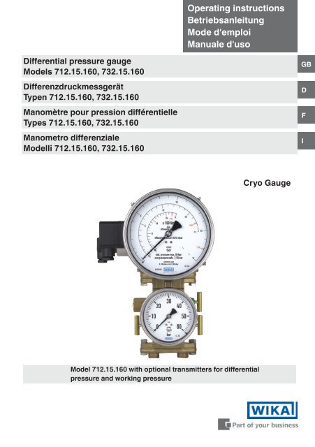
Operating instructions<br />
Betriebsanleitung<br />
<strong>Mode</strong> <strong>d'emploi</strong><br />
Manuale d'uso<br />
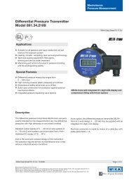
Differential pressure gauge<br />
<strong>Mode</strong>ls 712.15.160, 732.15.160<br />
Differenzdruckmessgerät<br />
Typen 712.15.160, 732.15.160<br />
Manomètre pour pression différentielle<br />
Types 712.15.160, 732.15.160<br />
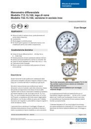
Manometro differenziale<br />
<strong>Mode</strong>lli 712.15.160, 732.15.160<br />
GB<br />
D<br />
F<br />
I<br />
Cryo Gauge<br />
<strong>Mode</strong>l 712.15.160 with optional transmitters for differential<br />
pressure and working pressure
GB<br />
Operating instructions for differential pressure gauges<br />
<strong>Mode</strong>ls 712.15.160, 732.15.160 Page 3-19<br />
D<br />
F<br />
I<br />
Betriebsanleitung für Differenzdruckmessgeräte<br />
Typen 712.15.160, 732.15.160 Seite 21-37<br />
<strong>Mode</strong> d’emploi pour manomètres pour pression différentielle<br />
Types 712.15.160, 732.15.160 Page 39-52<br />
Manuale d‘uso per manometri differenziali<br />
<strong>Mode</strong>lli 712.15.160, 732.15.160 Pagine 53-66<br />
© 2010 <strong>WIKA</strong> Alexander Wiegand SE & Co. KG<br />
All rights reserved. / Alle Rechte vorbehalten.<br />
<strong>WIKA</strong> ® is a registered trademark in various countries.<br />
<strong>WIKA</strong> ® ist eine geschützte Marke in verschiedenen Ländern.<br />
2<br />
Prior to starting any work, read the operating instructions!<br />
Keep for later use!<br />
Vor Beginn aller Arbeiten Betriebsanleitung lesen!<br />
Zum späteren Gebrauch aufbewahren!<br />
Lire le mode <strong>d'emploi</strong> avant de commencer toute opération !<br />
A conserver pour une utilisation ultérieure !<br />
Prima di iniziare ad utilizzare lo strumento, leggere il manuale d‘uso!<br />
Conservare per future consultazioni!<br />
<strong>WIKA</strong> operating instructions differential pressure gauge models 712.15.160, 732.15.160<br />
11265191.07 12/2012 GB/D/F/I
Contents<br />
Contents<br />
GB<br />
1. Safety 4<br />
2. General information 4<br />
3. Installation 4<br />
4. Differential pressure gauge 6<br />
5. Valve manifold with working pressure gauge (optional) 8<br />
6. Application note 9<br />
7. Adapter for process connection (optional) 9<br />
8. Transmitter for level measurement (optional) 9<br />
9. Transmitter for working pressure indication (optional) 13<br />
10. Switch contacts (optional) 14<br />
11. Maintenance 16<br />
12. Disposal 16<br />
Enclosure 1: EC-type examination certificate (Ex approval)<br />
for turning angle transmitter type 892.44 17<br />
Information<br />
This symbol provides you with information, notes and<br />
tips.<br />
11265191.07 12/2012 GB/D/F/I<br />
Warning!<br />
This symbol warns you against actions that can cause<br />
injury to people or damage to the instrument.<br />
<strong>WIKA</strong> operating instructions differential pressure gauge models 712.15.160, 732.15.160 3
1. Safety ... 3. Installation<br />
1. Safety<br />
GB<br />
WARNING!<br />
Before installation, commissioning and operation, ensure that the<br />
appropriate differential pressure gauge has been selected in terms of<br />
measuring range, design and specific measuring conditions.<br />
2. General information<br />
Only work on the gauge with the voltage disconnected.<br />
Non-observance can result in serious injury and/or damage to equipment.<br />
Only appropriately qualified skilled personnel should work on these<br />
instruments.<br />
These operating instructions are based upon the following:<br />
• EN 837-2: Selection and installation recommendations for pressure gauges<br />
• Data sheet PM 07.30: Differential pressure gauges models 712.15.160, 732.15.160<br />
• Data sheet PM 02.01, PM 02.02, PM 02.04: Bourdon tube pressure gauges<br />
3. Installation<br />
The installation of the differential pressure gauge should be carried out in accordance with the<br />
installation recommendations for pressure gauges per EN 837-2 /7.<br />
• Prior to the installation of the pressure gauge, the pipes should be thoroughly cleaned<br />
• The pressure gauge should be installed and operated such as to avoid exposure to<br />
vibration.<br />
Mounting by means of<br />
- rigid tailpipe and/or<br />
- 4 M8 threaded mounting holes incorporated in the body<br />
• The pressure gauges should be protected against contamination and high temperature<br />
fluctuations<br />
• The maximum permissible media/ambient temperature must not be exceeded<br />
Fitting of the pressure connections as per the j and i symbols<br />
j higher pressure ⇒ bottom pressure (p B ),<br />
i lower pressure ⇒ working pressure/overriding pressure (p D )<br />
p B = p FL + p D<br />
(with p FL = hydrostatic pressure of liquid = r • g • h)<br />
4<br />
<strong>WIKA</strong> operating instructions differential pressure gauge models 712.15.160, 732.15.160<br />
11265191.07 12/2012 GB/D/F/I
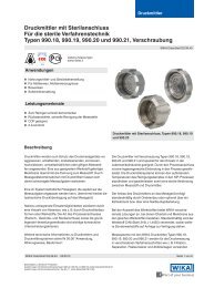
3. Installation<br />
Types of installation for level measurement<br />
Standard in cryogenic equipment<br />
(liquid gases)<br />
2 examples with condensate formation<br />
GB<br />
Filling hole<br />
Filling<br />
hole<br />
Condensate<br />
⇔<br />
Filling<br />
hole<br />
p D<br />
p D<br />
Constant<br />
level<br />
vessel<br />
p D<br />
Dp h<br />
Dp h<br />
Dp<br />
h<br />
p D p B<br />
Drain pipe Drain pipe<br />
pD<br />
p B<br />
i j<br />
i j<br />
i j<br />
Drain pipe<br />
Condensate<br />
Wall mounting<br />
Installation/fastening to the 4 mounting holes M8 / 2 fixing holes Ø 8.5<br />
Pressure connections G 1/4<br />
M8<br />
mounting holes<br />
11236396.02a<br />
Pressure connections<br />
G 1/4<br />
11265191.07 12/2012 GB/D/F/I<br />
Pressure<br />
equalising valve<br />
Isolating valve<br />
j<br />
Ø 8.5 fixing holes<br />
Test<br />
connection<br />
Isolating<br />
valve<br />
i<br />
<strong>WIKA</strong> operating instructions differential pressure gauge models 712.15.160, 732.15.160 5
3. Installation / 4. Differential pressure gauge<br />
Option<br />
GB<br />
Panel mounting<br />
Panel cut-out<br />
11248832.02<br />
Panel<br />
4. Differential pressure gauge<br />
The measuring range of the differential pressure gauge can, depending on the particular<br />
measurement system used, be adjusted within the limits given in the previous specifications<br />
table). Ideally, this adjustment should be made on a test bench, though it can also be carried<br />
out at the measuring point using a hand test pump.<br />
Measuring range limits<br />
Measuring cell Adjustable measuring ranges<br />
from<br />
to<br />
140 mbar 0 ... 40 mbar - 0 ... 140 mbar<br />
280 mbar 0 ... 80 mbar - 0 ... 280 mbar<br />
560 mbar 0 ... 160 mbar - 0 ... 560 mbar<br />
1130 mbar 0 ... 320 mbar - 0 ... 1130 mbar<br />
2300 mbar 0 ... 650 mbar - 0 ... 2300 mbar<br />
4000 mbar 0 ... 1150 mbar - 0 ... 4000 mbar<br />
Cover cap for adjustable<br />
measuring span<br />
Adjustable measuring span<br />
6<br />
Adjustable measuring span<br />
Allen key<br />
(included in delivery)<br />
Turn clockwise: reduce measuring range<br />
Turn anticlockwise: expand measuring range<br />
<strong>WIKA</strong> operating instructions differential pressure gauge models 712.15.160, 732.15.160<br />
11265191.07 12/2012 GB/D/F/I
4. Differential pressure gauge<br />
1. The span adjustment, situated at the ‚4 o‘clock‘ point on the instrument case, is accessible<br />
through the case by removing the cover cap.<br />
2. Charge the instrument to the desired nominal pressure.<br />
GB<br />
3. To set the pointer to the span value, using an allen key (size 3 mm) inserted into the funnel,<br />
turn it either clockwise (reduce the measuring range) or anticlockwise (expand the measuring<br />
range). The gauge will then be fully adjusted to the required measuring range.<br />
4. If the gauge is equipped with a transmitter <strong>Mode</strong>l 89x.44, then this procedure will also<br />
adjust the output signal to the new measuring range.<br />
5. After completing the adjustment the equipment should be resealed with the cover cap.<br />
Interchangeable scales (optional)<br />
1. Loosen the clamp clip on the case of the<br />
differential pressure gauge and remove the<br />
cover ring complete with the lens.<br />
<br />
<br />
<br />
2. Loosen and remove the knurled screw.<br />
3. Remove all three scales, place the desired<br />
scale on top and put them back in place.<br />
4. Reinsert the knurled screw and tighten it.<br />
Mount the cover ring and lens and fasten<br />
the clamp clips again.<br />
Additional pressure connections<br />
<br />
Legend<br />
Clamp clip<br />
Cover ring<br />
Knurled screw<br />
Scales<br />
G 1/4 pressure connections<br />
• Three additional G ¼ female threads are<br />
available on the minus measurement chamber<br />
(the right measuring cell flange when viewed<br />
from the back) e.g. for connecting a pressure<br />
switch, safety valve or A-10 Cryo or IS-20<br />
transmitters<br />
11224380.02BA<br />
11265191.07 12/2012 GB/D/F/I<br />
• Two G ¼ female threads are available on<br />
the plus measurement chamber (the left cell<br />
flange when viewed from the back) e.g. for<br />
recalibration<br />
Mounting holes M8<br />
G 1/4 pressure connections<br />
<strong>WIKA</strong> operating instructions differential pressure gauge models 712.15.160, 732.15.160 7
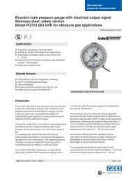
5. Valve manifold with working pressure gauge (optional)<br />
5. Valve manifold with working pressure gauge (optional)<br />
The compact optional flanged valve manifold for an NG 100 working pressure gauge allows<br />
GB the central measurement of level and working pressure in a single device.<br />
• To isolate line pressures without interrupting<br />
the process, enabling gauge<br />
removal/examination and protecting the<br />
gauge against overpressure of n-times<br />
rated pressure which may occur during<br />
plant pressure testing.<br />
• To protect the gauge against pressure<br />
surges/pressure spikes, and thus against<br />
unspecified operating conditions<br />
Test connection<br />
M20 x 1.5<br />
Isolating valve<br />
i<br />
8<br />
Working<br />
pressure gauge<br />
NS 100<br />
Pressure equalising<br />
valve<br />
Isolating valve<br />
j<br />
11236396.01BA<br />
• For gauge shut-downs, if no measurements<br />
are required for long operating<br />
periods, i.e. if only occasional measurements<br />
are necessary (to increase service<br />
life of those differential and working pressure<br />
gauges with a high frequency of pressure<br />
fluctuations).<br />
• Recalibration of differential pressure<br />
gauges (tank volume display)<br />
a) Open pressure equalising valve<br />
b) Close the plus and minus shut-off valves,<br />
and then close the pressure equalising<br />
valve again<br />
c) Connect the pressure standard and test pump using the additional G ¼ female port in<br />
the plus chamber of the measuring system<br />
d) Remove the test connection screw from the minus side valve manifold<br />
e) The plus side can then be pressurised<br />
f) After adjustment:<br />
- Close the air bleed screw<br />
- Disconnect the pressure standard and test pump and close the connection<br />
- Open the integrated pressure equalising valve<br />
- Slowly open first the plus and then the minus shut-off valve<br />
- Close the pressure equalising valve<br />
• Test connection M20 x 1.5 for checking the working pressure gauge<br />
The pressure equalising valve allows a zero point control during operation (with open valve).<br />
• While the media is flowing from the higher pressure side to the other side, the differential<br />
pressure at the pressure gauge drops to zero (the differential pressure display must be at<br />
zero, i.e. within the zero tolerance range which shows that the gauge is working correctly).<br />
• A zero adjustment can be made using the standard integrated,<br />
adjustable pointer (remove snap fit bezel incl. window and<br />
sealing ring beforehand). Twisting the slotted screw on the<br />
adjustable pointer you can adjust the zero point.<br />
After completing the zero adjustment, the snap fit bezel,<br />
incl. window and ‚o‘-ring seal, must be correctly re-fitted<br />
and the pressure equalising valve must then be closed again.<br />
• Subsequently the zero point of versions with integrated<br />
transmitter (see page 9) should be checked.<br />
Slotted<br />
screw<br />
<strong>WIKA</strong> operating instructions differential pressure gauge models 712.15.160, 732.15.160<br />
11265191.07 12/2012 GB/D/F/I
6. Application note ... 8. Transmitter for level measurement<br />
6. Application note<br />
For dangerous media such as, for example, oxygen, acetylene,<br />
combustible or acidic media, as well as for pressure vessels,<br />
the general directives, and also the prevailing directives/guidelines<br />
must also be adhered to.<br />
GB<br />
7. Adapter for process connection (optional)<br />
The adapters can be flange-connected either directly to<br />
the differential pressure gauge or to the valve manifold.<br />
5 different process connections are available:<br />
• 2 x G 1/4, female, connection distance 31 mm or 54 mm<br />
• 2 x 1/4 NPT, female, connection distance 31 mm, 37 mm or 54 mm<br />
With a single order, all parts necessary for fitting to the differential pressure gauge or to the<br />
valve manifold are included in the scope of supply:<br />
2 x hexagon screw M8 x 16, 2 x hexagon screw M8 x 28, 2 x nut M8 and 2 x O-Ring seal<br />
8. Transmitter for level measurement (optional)<br />
• Standard version model 891.44<br />
• Ex version model 892.44<br />
<strong>WIKA</strong> differential pressure gauges with an integrated <strong>Mode</strong>l 89x.44 transmitter combines all<br />
the advantages of an on-site mechanical display with the demands modern industry makes<br />
for electrical signal transmission for the acquisition of measured values.<br />
The transmitter is integrated into the housing of the level display. The measurement span<br />
(electrical output signal) is set automatically by the mechanical display, i.e. the scale over a<br />
swept angle of 270 degrees corresponds to 4 …20 mA (see section 4. Differential pressure<br />
gauge).<br />
With multiple scales or interchangeable<br />
dials (optional) the output signal of<br />
4 ... 20 mA corresponding to each,<br />
can be stored in a microprocessor.<br />
11265191.07 12/2012 GB/D/F/I<br />
The output signal can be changed over<br />
to the desired fluid type by rotating the<br />
optional BCD switch (accessible through<br />
a cover cap on the left side of the case)<br />
using a screwdriver.<br />
Electrical zero point (with option BCD switch)<br />
BCD switch (scale selection switch) and<br />
zero point button (cover cap removed)<br />
If a zero point compensation is required (e.g. after mechanical zero point correction), press<br />
the zero point button for approx. 1 sec. within 30 sec. with the voltage disconnected (remove<br />
plug) and with the pressure compensation valve open.<br />
<strong>WIKA</strong> operating instructions differential pressure gauge models 712.15.160, 732.15.160 9
8. Transmitter for level measurement<br />
Electrical zero point (without option BCD switch)<br />
GB<br />
If the mechanical zero point is changed by means of the<br />
adjustable pointer, the electrical zero point must be reset to<br />
the mechanical zero point.<br />
First depressurise the pressure gauge.<br />
Loosen the complete cable hood on the right-hand side of<br />
the pressure gauge by completely unscrewing the screw <br />
on the top of the cable hood cover using an appropriate<br />
screwdriver (0.6 x 3.5 mm).<br />
Extract the screw. Remove the cable hood with the<br />
socket insert from the cable socket base and thus<br />
separate the pressure gauge from the power supply.<br />
Remove the cable hood cover from the cable hood <br />
and push the socket insert out downwards through the<br />
entire cable hood .<br />
Use a short stranded wire with bare points at both ends<br />
(max. permissible resistance 30 Ω) to bridge contacts 5 and<br />
6 on the socket insert.<br />
Reassemble the plug in reverse order. Place the plug, with<br />
the attached piece of stranded wire, onto the pin insert ,<br />
and thus reestablish the power supply.<br />
<br />
<br />
<br />
<br />
<br />
Within a max. 30 seconds the new zero point will be stored<br />
within the electronics. During this period, the current in the<br />
loop will increase to 9.5 mA.<br />
<br />
The new zero point also remains stored in the case of a<br />
power failure.<br />
Loosen the plug again in the same sequence as described<br />
above and remove the piece of stranded wire. After<br />
reassembling the plug, the electrical output signal will once<br />
more correspond to the indication of the mechanical pointer.<br />
10<br />
Ensure the seals are properly and<br />
securely reinstalled to maintain the<br />
protection class.<br />
<strong>WIKA</strong> operating instructions differential pressure gauge models 712.15.160, 732.15.160<br />
<br />
Screw<br />
Cable hood cover<br />
Cable hood<br />
Socket insert<br />
Cable socket base<br />
Seals<br />
11265191.07 12/2012 GB/D/F/I
8. Transmitter for level measurement<br />
11265191.07 12/2012 GB/D/F/I<br />
Specifications<br />
<strong>Mode</strong>ls 891.44 and 892.44 (Ex Version)<br />
Power supply UB<br />
for Non-Ex version DC 12 V < UB ≤ 30 V<br />
for Ex version<br />
see the section ‚Ex protection‘!<br />
Permissible residual ripple % of span/10 V ≤ 0.1<br />
Supply voltage effect % ss ≤ 10<br />
Output signal<br />
4 … 20 mA, 2-wire system<br />
Permissible max. load RA for Non-Ex versions, <strong>Mode</strong>l 891.44:<br />
RA ≤ (UB - 12 V) / 0.02 A with RA in Ω and UB in Volt<br />
for Ex versions, <strong>Mode</strong>l 892.44:<br />
RA ≤ (UB - 14 V) / 0.02 A with RA in Ω and UB in Volt<br />
Effect of load % of span ≤ 0.1<br />
Output signal adjustment<br />
Zero point, electrical Adjustment of zero point through brief bridging of terminals 5 and 6,<br />
or using the „scale selection switch“ option, selectable via button 1)<br />
Scale selection<br />
4 scales selectable via BCD switch<br />
Linearity % of span ≤ 1.0 (limit point calibration)<br />
Permissible<br />
ambient temperatures °C -40 … +80, -40 … +60 with oxygen<br />
Compensated temp. range °C -40 … +80<br />
Temperature coefficients in<br />
compensated temp. range<br />
Mean TK of zero % of span/10 K ≤ 0.3<br />
Mean TK of span % of span/10 K ≤ 0.3<br />
Ex protection<br />
according to EC-Type Examination Certificate<br />
BSV 08 ATEX E 018 X for <strong>Mode</strong>l 892.44<br />
Ex certification<br />
EEx II 2G EEx ia IIC T6<br />
Conformity specifications<br />
Power supply Ui DC 14 … 30 V<br />
Short circuit rating Ii mA max. 100<br />
Rating Pi W max. 1<br />
Internal capacitance Ci nF 12<br />
Internal inductance Li mH negligible<br />
Medium temperature °C -40 … +80, -40 … +60 with oxygen<br />
Ambient temperature °C -40 … +60 (T6)<br />
CE-Conformity interference emission and immunity per EN 61326<br />
Wiring<br />
L-connector (screw terminals up to 2.5 mm²)<br />
Wiring protection<br />
protected against reverse polarity and overvoltage<br />
Ingress protection IP 65 per EN 60529 / IEC 529<br />
Wiring details,<br />
2-wire<br />
1) Only possible within 30 seconds of connecting the supply voltage<br />
Earth, connected<br />
to case 2)<br />
UB+/Sig+<br />
0V/Sig-<br />
Terminals 3, 4, 5 and 6: only for internal<br />
application<br />
2) This connection must not be used<br />
for equipotential bonding. The<br />
instrument must be incorporated in<br />
the equipotential bonding via the<br />
process connection.<br />
<strong>WIKA</strong> operating instructions differential pressure gauge models 712.15.160, 732.15.160 11<br />
GB
8. Transmitter for level measurement<br />
Trouble shooting<br />
GB<br />
Defect Possible reason Remedy<br />
No signal output Failure of power supply Check power supply and wiring<br />
Wiring interrupted (or broken) replace defective components<br />
Transmitter incorrectly wired Check wiring;<br />
if necessary rectify it<br />
No pressure<br />
Check tailpipes<br />
Open press. compensation valve Close pressure compensation valve<br />
Electronic defect e.g. through Return pressure gauge to<br />
incorrect supply voltage manufacturer for repair<br />
or stray voltage spikes<br />
Steady signal Pressure entry blocked Check tailpipes and pressure entry<br />
despite pressure<br />
bore, if necessary clean it carefully<br />
variation Open press. compensation valve Close pressure compensation valve<br />
Electronic defect e.g. through Return pressure gauge to<br />
incorrect supply voltage manufacturer for repair<br />
or stray voltage spikes<br />
Ferngeber defekt nach<br />
Return pressure gauge to<br />
mechanischer Überbelastung manufacturer for repair<br />
Steady and too high Electronic defect through Return pressure gauge to<br />
signal despite of incorrect supply voltage manufacturer for repair<br />
pressure variation or stray voltage spikes<br />
Full span reading too low Supply voltage too low<br />
Adjust supply voltage<br />
Load impedance too high Consider permissible max. load<br />
Wrong scale selected<br />
Check position of scale selection<br />
switch<br />
Zero signal too low Wrong zero compensation Readjust zero point<br />
Zero signal too high Wrong zero compensation Readjust zero point<br />
Transmitter over-pressured Return pressure gauge to<br />
manufacturer for repair<br />
12<br />
<strong>WIKA</strong> operating instructions differential pressure gauge models 712.15.160, 732.15.160<br />
11265191.07 12/2012 GB/D/F/I
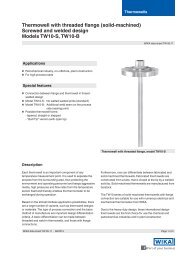
9. Transmitter for working pressure indication<br />
9. Transmitter for working pressure indication (optional)<br />
Standard version model A-10<br />
or Ex version model IS-20<br />
The transmitters for the working pressure<br />
are screwed in sideways, on the left side of<br />
the minus measurement chamber and can,<br />
if necessary, be retrofitted on-site.<br />
Pressure connection for Transmitter: G 1/4<br />
(male)<br />
GB<br />
Transmitter for working<br />
pressure indication<br />
Specifications A-10 IS-20<br />
Data sheet PE 81.60 PE 81.50<br />
Design standard intrinsically safe<br />
Pressure ranges bar 0 ... 6 to 0 ... 60 0 ... 6 to 0 ... 60<br />
Outputs mA 4 ... 20 4 ... 20 (line transformer)<br />
Medium temperature °C -30 ... +100 -20 ... +80<br />
Ambient temperature °C -30 ... +100 -20 ... +80<br />
Wetted parts stainless steel stainless steel<br />
Power supply UB DC 8 V < UB ≤ 30 V 10 V < UB ≤ 30 V<br />
Maximum load RA Ohm RA ≤ (UB - 8 V) / 0.02 A RA ≤ (UB - 10 V) / 0.02 A<br />
Accuracy<br />
BFSL % of span ≤ 0.5 ≤ 0.25<br />
Compensated temperature<br />
range<br />
°C 0 ... +80 °C 0 ... +80 °C<br />
Wiring details,<br />
2-wire<br />
Non hazardous<br />
area<br />
Hazardous<br />
(classified) area<br />
11265191.07 12/2012 GB/D/F/I<br />
The corresponding operating instructions are included in the delivery<br />
of each differential pressure gauge with integrated transmitter for<br />
working pressure indication.<br />
<strong>WIKA</strong> operating instructions differential pressure gauge models 712.15.160, 732.15.160 13
10. Switch contacts<br />
GB<br />
10. Switch contacts (optional)<br />
These switch contacts are fitted into the case of a pressure gauge and intended to make or<br />
break an electric control circuit triggered by the position of the instrument‘s pointer.<br />
Versions<br />
Single and double magnetic snap-action contacts or single and double inductive alarm<br />
sensors. Please refer to data sheet AC 08.01 for technical data.<br />
The modular switch contact is a self-contained unit, which can be built onto the pressure<br />
gauge within a few minutes.<br />
The switch contacts provide IP65 ingress protection even for oil-filled gauges. The connection<br />
to the instrument pointer is made by means of a special fork so that a carrying pin at<br />
the pointer itself is not necessary. By means of this simple mounting, the instrument can be<br />
converted into a contact measuring instrument quickly and inexpensively.<br />
The switch contacts mainly comprise:<br />
• the pre-wired switch contact, which is provided with a special foot and a fork coupling<br />
• a transparent hood (polycarbonate) with dovetail lead into which the alarm contact is<br />
pushed and which is fastened by means of a recessed head screw<br />
• a 4-pin plug socket, injection-moulded or welded to the transparent cover<br />
• an adjustable lock, mounted in the middle of the transparent cover.<br />
The set pointers of the built-in<br />
switch contact are adjusted, to<br />
the value at which the contact<br />
should switch, from the outside<br />
via the adjustable lock using a<br />
separate or a rigidly mounted<br />
key.<br />
The switch contacts are<br />
designed to allow the instrument<br />
pointer to move beyond<br />
the adjusted set pointer after<br />
contact actuation takes place,<br />
with the contact remaining<br />
actuated.<br />
The design therefore guarantees<br />
a stable switching condition,<br />
which corresponds to<br />
the position of the instrument<br />
pointer, even if the power fails.<br />
14<br />
Plug screw<br />
Plug with cable<br />
Plug seal<br />
Plug socket<br />
Type plate screws<br />
Type plate<br />
Front plate<br />
Connection<br />
Transparent hood<br />
Special foot<br />
with dovetail lead<br />
Spiral spring Coupling fork<br />
Ruby bearing<br />
Spanner<br />
Adjustable lock<br />
Metal flag<br />
Adjustable pin<br />
Carrying arm<br />
Contact pin<br />
Magnet carrying<br />
plate<br />
Screw-in magnet<br />
Desired value<br />
indicator, red<br />
Contact arm with<br />
plate spring<br />
Carrying pin of coupling fork<br />
Bayonet rim<br />
<strong>WIKA</strong> operating instructions differential pressure gauge models 712.15.160, 732.15.160<br />
11265191.07 12/2012 GB/D/F/I
10. Switch contacts<br />
Mounting of switch contacts<br />
<br />
<br />
GB<br />
<br />
<br />
11265191.07 12/2012 GB/D/F/I<br />
Legend<br />
Self-contained unit with switch contact for level measurement<br />
Self-contained unit with switch contact for working pressure<br />
<br />
Connector plug<br />
First the snap fit style bezel with sealing ring, and the gauge window, must be removed. Prior<br />
to attaching the transparent hood to the measuring instrument, the contacts must be adjusted<br />
in accordance with their operating range.<br />
Using the magnetic snap-action contact, the magnetic retention force must be adapted to the<br />
instrument-specific conditions by adjusting (twisting) the screw-in magnet. The magnet must<br />
then be protected against unintentional adjustment by using an appropriate locking varnish.<br />
The small plate spring at the flexible contact arm must be angled accordingly.<br />
The fully-adjusted unit must now be fitted to the gauge, together with the snap-fit bezel, and<br />
aligned to the extent that the fork coupling guiding the flexible contact arms grips over the<br />
gauge pointer without touching the dial. Should this occur, the carrying fork must be shortened<br />
using a suitable cutting tool.<br />
The contacts are best adjusted when they are factory-fitted.<br />
By snapping the bezel onto the case, the whole contact unit will be fixed to the pressure<br />
gauge.<br />
Connector plug<br />
As counterpart to the connector base welded<br />
onto the transparent hood<br />
• Material: PA 6 - GF 30<br />
• Colour: grey<br />
• Connection: stripped and tinned wires<br />
• Ingress protection: IP 65 per EN 60529 / IEC 529<br />
Gasket<br />
For magnetic snap-action contacts:<br />
• Connector plug 3 poles + l (250 V max.)<br />
with 2 m cable 4 x 1.0 mm 2<br />
For inductive alarm sensors:<br />
Low voltage execution without protective earth conductor<br />
• Connector plug 4 poles (50 V max.)<br />
with 2 m cable 4 x 0.75 mm 2<br />
Extent of delivery: 1 plug with cable,<br />
1 central screw M3 x 20 and 1 gasket<br />
<strong>WIKA</strong> operating instructions differential pressure gauge models 712.15.160, 732.15.160 15
10. Switch contacts ... 12. Disposal<br />
Terminal configuration<br />
GB<br />
Magnetic snap-action<br />
contacts:<br />
• Single contact,<br />
NS 100<br />
green/yellow<br />
blue<br />
brown<br />
green/yellow<br />
1st contact<br />
common<br />
• Double contact,<br />
NS 100<br />
green/yellow<br />
blue<br />
brown<br />
black<br />
green/yellow<br />
1st contact<br />
common<br />
2nd contact<br />
• Single contact,<br />
NS 160<br />
green/yellow<br />
brown<br />
black<br />
green/yellow<br />
common<br />
2nd contact<br />
• Double contact,<br />
NS 160<br />
green/yellow<br />
blue<br />
brown<br />
black<br />
green/yellow<br />
1st contact<br />
common<br />
2nd contact<br />
Inductive alarm sensors:<br />
• Single contact,<br />
NS 100 and 160<br />
yellow<br />
white<br />
1st contact +<br />
1st contact -<br />
• Double contact,<br />
NS 100 and 160<br />
violet<br />
yellow<br />
black<br />
white<br />
1st contact +<br />
1st contact -<br />
2nd contact -<br />
2nd contact +<br />
11. Maintenance<br />
<strong>WIKA</strong> differential pressure gauges require no maintenance or servicing and will give very long<br />
service when handled and operated properly.<br />
12. Disposal<br />
Incorrect disposal can put the environment at risk.<br />
Dispose of instrument components and packaging materials in an environmentally compatible<br />
way and in accordance with the country-specific waste disposal regulations.<br />
16<br />
<strong>WIKA</strong> operating instructions differential pressure gauge models 712.15.160, 732.15.160<br />
11265191.07 12/2012 GB/D/F/I
Enclosure 1<br />
GB<br />
11265191.07 12/2012 GB/D/F/I<br />
<strong>WIKA</strong> operating instructions differential pressure gauge models 712.15.160, 732.15.160 17
Enclosure 1<br />
GB<br />
18<br />
<strong>WIKA</strong> operating instructions differential pressure gauge models 712.15.160, 732.15.160<br />
11265191.07 12/2012 GB/D/F/I
Enclosure 1<br />
GB<br />
11265191.07 12/2012 GB/D/F/I<br />
<strong>WIKA</strong> operating instructions differential pressure gauge models 712.15.160, 732.15.160 19
GB<br />
20<br />
<strong>WIKA</strong> operating instructions differential pressure gauge models 712.15.160, 732.15.160<br />
11265191.07 12/2012 GB/D/F/I
Inhalt<br />
Inhalt<br />
1. Sicherheit 22<br />
2. Allgemeines 22<br />
3. Montage 22<br />
4. Differenzdruckanzeige 24<br />
5. Ventilblock mit Betriebsdruckanzeige (Option) 26<br />
6. Applikationshinweis 27<br />
7. Adapter für Prozessanschluss (Option) 27<br />
8. Transmitter für Füllstandanzeige (Option) 27<br />
9. Transmitter für Betriebsdruckanzeige (Option) 31<br />
10. Schaltkontakte (Option) 32<br />
11. Wartung 34<br />
12. Entsorgung 34<br />
Anlage 1: EG-Baumusterprüfbescheinigung<br />
(Ex-Zulassung) für Drehwinkelgeber Typ 892.44 35<br />
D<br />
Information<br />
Dieses Zeichen gibt Ihnen Informationen, Hinweise<br />
oder Tipps.<br />
11265191.07 12/2012 GB/D/F/I<br />
Warnung!<br />
Dieses Symbol warnt Sie vor Handlungen, die Schäden<br />
an Personen oder am Gerät verursachen können.<br />
<strong>WIKA</strong> Betriebsanleitung Differenzdruckmessgerät Typen 712.15.160, 732.15.160<br />
21
1. Sicherheit ... 3. Montage<br />
1. Sicherheit<br />
D<br />
WARNUNG!<br />
Vor Montage, Inbetriebnahme und Betrieb sicherstellen, dass das richtige<br />
Differenzdruckmessgerät hinsichtlich Messbereich, Ausführung und spezifischen<br />
Messbedingungen ausgewählt wurde.<br />
Alle Arbeiten dürfen nur im spannungslosen Zustand erfolgen.<br />
2. Allgemeines<br />
Bei Nichtbeachten können schwere Körperverletzungen und/oder<br />
Sachschäden auftreten.<br />
Nur entsprechend qualifiziertes Fachersonal darf an diesen Geräten<br />
arbeiten.<br />
Vorliegende Betriebsanleitung baut auf folgende Informationen auf:<br />
• EN 837-2: Auswahl- und Einbauempfehlungen für Druckmessgeräte<br />
• Datenblatt PM 07.30: Differenzdruckmessgeräte Typen 712.15.160, 732.15.160<br />
• Datenblatt PM 02.01, PM 02.02, PM 02.04: Druckmessgeräte mit Rohrfeder<br />
3. Montage<br />
Die Montage des Differenzdruckmessgerätes erfolgt in Anlehnung an die Einbauempfehlungen<br />
für Druckmessgeräte nach EN 837-2 /7.<br />
• Messleitungen vor der Gerätemontage gründlich durch Abklopfen und Ausblasen<br />
oder Durchspülen reinigen<br />
• Messgeräte sollen erschütterungsfrei montiert und betrieben werden<br />
Befestigung über: - starre Messleitungen und/oder<br />
- 4 Montagebohrungen M8 im Messflansch<br />
• Messgeräte sollen vor Verschmutzung und starken Temperaturschwankungen<br />
geschützt sein<br />
• Maximal zulässige Messstoff-/Umgebungstemperatur darf nicht überschritten werden<br />
Montage des Druckanschlusses nach angebrachten Symbolen j und i<br />
j hoher Druck ⇒ Bodendruck (p B )<br />
i niedriger Druck ⇒ Betriebsdruck/Überlagerungsdruck (p D )<br />
p B = p FL + p D<br />
(wobei p FL = hydrostatischer Druck der Flüssigkeit = r • g • h)<br />
22<br />
<strong>WIKA</strong> Betriebsanleitung Differenzdruckmessgerät Typen 712.15.160, 732.15.160<br />
11265191.07 12/2012 GB/D/F/I
3. Montage<br />
Montagearten zur Füllstandsmessung<br />
Standard bei Tiefkälteanlagen<br />
(verflüssigte Gase)<br />
2 Beispiele mit Kondensatanfall<br />
Zufuhr<br />
Zufuhr<br />
Kondensat<br />
⇔<br />
Zufuhr<br />
D<br />
pD<br />
p D<br />
Niveaugefäß<br />
p D<br />
Dp h<br />
Dp h<br />
Dp<br />
h<br />
p D p B<br />
Entnahme Entnahme<br />
pD<br />
p B<br />
i j<br />
i j<br />
i j<br />
Entnahme<br />
Kondensat<br />
Montage an Wand<br />
Anbringung/Befestigung an den 4 Montagebohrungen M8 / 2 Befestigungsbohrungen Ø 8,5<br />
Druckanschlüsse G 1/4<br />
Montagebohrungen<br />
M8<br />
11236396.02a<br />
Druckanschlüsse<br />
G 1/4<br />
11265191.07 12/2012 GB/D/F/I<br />
Druckausgleichsventil<br />
Absperrventil<br />
j<br />
Befestigungsbohrungen<br />
Ø 8,5<br />
<strong>WIKA</strong> Betriebsanleitung Differenzdruckmessgerät Typen 712.15.160, 732.15.160<br />
Prüfanschluss<br />
Absperrventil<br />
i<br />
23
3. Montage / 4. Differenzdruckanzeige<br />
Option<br />
Schalttafeleinbau<br />
Schalttafelausschnitt<br />
D<br />
11248832.02<br />
Schalttafel<br />
4. Differenzdruckanzeige<br />
Die Messspanne des Differenzdruckmessgerätes kann je nach Messzelle auf die in der Tabelle<br />
angegebenen Messbereichsgrenzen eingestellt werden. Die Einstellung sollte zweckmäßig<br />
auf dem Prüfstand erfolgen, kann jedoch auch direkt an der Messstelle mittels Handprüfpumpe<br />
vorgenommen werden.<br />
Messbereichsgrenzen<br />
Messzelle Einstellbare Messbereiche<br />
von<br />
bis<br />
140 mbar 0 ... 40 mbar - 0 ... 140 mbar<br />
280 mbar 0 ... 80 mbar - 0 ... 280 mbar<br />
560 mbar 0 ... 160 mbar - 0 ... 560 mbar<br />
1130 mbar 0 ... 320 mbar - 0 ... 1130 mbar<br />
2300 mbar 0 ... 650 mbar - 0 ... 2300 mbar<br />
4000 mbar 0 ... 1150 mbar - 0 ... 4000 mbar<br />
Verschlusskappe<br />
zur Spanneverstellung<br />
Spanneverstellung<br />
24<br />
Spanneverstellung<br />
Rechtsdrehen: kleinerer Messbereich<br />
Linksdrehen: größerer Messbereich<br />
Inbus-Schraubendreher<br />
(im Lieferumfang enthalten)<br />
<strong>WIKA</strong> Betriebsanleitung Differenzdruckmessgerät Typen 712.15.160, 732.15.160<br />
11265191.07 12/2012 GB/D/F/I
4. Differenzdruckanzeige<br />
1. Die Spanneverstellung ist am Gehäuseumfang bei 4 Uhr durch Abnehmen der<br />
Verschlusskappe zugänglich.<br />
2. Das Gerät mit dem gewünschten Nenndruck beaufschlagen.<br />
3. Mittels Inbus-Schraubendreher (SW 3 mm) in die Trichterführung eintauchen und durch<br />
Rechts- (kleinerer Messbereich) oder Linksdrehen (größerer Messbereich) den Zeiger auf<br />
Endwert verstellen. Danach ist das Messgerät bereits auf den gewünschten Messbereich<br />
eingestellt.<br />
D<br />
4. Ist das Messgerät mit einem Ferngeber Typ 89x.44 ausgerüstet (siehe Seite 23), so ist<br />
mit dieser Prozedur auch das Ausgangssignal auf den neuen Messbereich eingestellt.<br />
5. Nach Beendigung der Einstellung ist das Gerät wieder mit der Verschlusskappe zu<br />
verschließen.<br />
Wechselbare Skalen (Option)<br />
<br />
<br />
<br />
1. Spannbügel am Gehäuse des Differenzdruck-Messgerätes<br />
lösen und Überring<br />
mit Sichtscheibe entfernen<br />
2. Rändelschraube lösen und ganz herausnehmen<br />
3. Alle drei Skalen entnehmen, gewünschte<br />
Skale oben auf legen und wieder einlegen<br />
4. Rändelschraube aufsetzen und festziehen,<br />
Überring mit Sichtscheibe montieren und<br />
die Spannbügel wieder einschnappen<br />
<br />
Legende<br />
Spannbügel<br />
Überring<br />
Rändelschraube<br />
Skalen<br />
Druckanschlüsse G 1/4<br />
Zusätzliche Druckanschlüsse<br />
• Drei zusätzliche G ¼ Innengewinde an Minusmessstoffkammer<br />
(rechter Messzellenflansch<br />
bei Ansicht des Gerätes von hinten) z. B. zum<br />
Anschluss eines Druckschalters, Sicherheitsventiles<br />
oder Messumformers Typ A-10 Cryo<br />
bzw. IS-20<br />
11224380.02BA<br />
11265191.07 12/2012 GB/D/F/I<br />
• Zwei G ¼ Innengewinde an Plusmessstoffkammer<br />
(linker Messzellenflansch bei<br />
Ansicht des Gerätes von hinten) z. B.<br />
zur Rekalibrierung<br />
Montagebohrungen M8<br />
Druckanschlüsse G 1/4<br />
<strong>WIKA</strong> Betriebsanleitung Differenzdruckmessgerät Typen 712.15.160, 732.15.160<br />
25
5. Ventilblock mit Betriebsdruckanzeige (Option)<br />
5. Ventilblock mit Betriebsdruckanzeige (Option)<br />
Der optional anflanschbare kompakte Ventilblock mit Betriebsdruck-Messgerät NG 100<br />
ermöglicht die zentrale Messung von Füllstand und Betriebsdruck in einem Gerät.<br />
• Absperrung der Messleitungsdrücke ohne<br />
Störung des Betriebsablaufes<br />
D<br />
- zur Gerätedemontage/-prüfung<br />
- zum Schutz des Gerätes gegen unzulässige<br />
Überdruckbelastung bei n-facher<br />
Prüfdruckbelastung von Anlagen<br />
• Schutz des Gerätes gegen Druckstöße/<br />
-schläge und damit undefinierten<br />
Betriebsverhältnissen<br />
Prüfanschluss<br />
M20 x 1,5<br />
Absperrventil<br />
i<br />
26<br />
Betriebsdruck-<br />
Messgerät<br />
NG 100<br />
Druckausgleichsventil<br />
Absperrventil<br />
j<br />
11236396.01BA<br />
• Gerätestilllegung, wenn über längere Betriebszeiten<br />
keine Messung erforderlich,<br />
d.h. nur sporadische Messungen (zur<br />
Erhöhung der Lebensdauer von Differenzund<br />
Betriebsdruck-Messgeräten mit hoher<br />
Frequenz der Druckwechsel)<br />
• Rekalibrierung des Differenzdruckmessgerätes<br />
(Tankinhaltsanzeige)<br />
a) Druckausgleichsventil öffnen<br />
b) Plus- und Minusabsperrhahn schließen<br />
und anschl. Druckausgleichsventil wieder<br />
schließen<br />
c) Über zusätzliches G ¼ Innengewinde in der Pluskammer des Messsystems wird<br />
Drucknormal und Druckerzeuger angeschlossen<br />
d) Im Ventilblock auf der Minusseite Prüfanschluss-Schraube entfernen<br />
e) Plusseite kann jetzt mit Druck beaufschlagt werden<br />
f) Nach erfolgter Justage:<br />
- Prüfanschlussschraube wieder schließen<br />
- Drucknormal und Druckerzeuger wieder entfernen und Anschluss verschließen<br />
- Druckausgleichsventil öffnen<br />
- zuerst Plus-, dann Minusabsperrhahn langsam öffnen<br />
- Druckausgleichsventil wieder schließen<br />
• Prüfanschluss M20 x 1,5 für die Überprüfung des Betriebsdruck-Messgerätes<br />
Mit dem Druckausgleichsventil wird eine Nullpunktkontrolle im laufenden Betriebsprozess<br />
(bei geöffnetem Ventil) ermöglicht.<br />
• Der Messstoff strömt von der Seite höheren Druckes nach der Gegenseite, Differenz-druck<br />
am Messgerät fällt auf Null (Differenzdruckanzeige muss auf Null, d.h. in den Bereich des<br />
Nullpunkt-Toleranzbandes gehen, Gerätefunktion ist damit in Ordnung).<br />
• Bei Abweichung kann eine Nullpunktkorrektur über den<br />
standardmäßig eingebauten Verstellzeiger erfolgen (vorher die<br />
Spannbügel lösen und Sichtscheibe und Dichtung entfernen).<br />
Die Nullpunkt-Verstellung wird durch Verdrehen der Schlitzschraube<br />
am Verstellzeiger erreicht. Nach erfolgter Nullpunktkorrektur<br />
Schnappring incl. Sichtscheibe und Dichtung<br />
wieder befestigen und Druckausgleichsventil schließen.<br />
• Anschließend ist bei Ausführungen mit integriertem Transmitter<br />
auch dessen Nullpunkt zu kontrollieren (siehe Seite 27).<br />
Schlitzschraube<br />
<strong>WIKA</strong> Betriebsanleitung Differenzdruckmessgerät Typen 712.15.160, 732.15.160<br />
11265191.07 12/2012 GB/D/F/I
6. Applikationshinweis ... 8. Transmitter für Füllstandanzeige<br />
6. Applikationshinweis<br />
Bei gefährlichen Messstoffen, wie z. B. Sauerstoff, Acetylen, brennbaren<br />
oder giftigen Stoffen, sowie bei Druckbehältern etc., sind über die allgemeinen<br />
Regeln hinaus die bestehenden Vorschriften/Richtlinien zu beachten.<br />
7. Adapter für Prozessanschluss (Option)<br />
D<br />
11265191.07 12/2012 GB/D/F/I<br />
Die Adapter können entweder direkt an das Differenzdruckmessgerät<br />
oder an den Ventilblock angeflanscht werden.<br />
5 verschiedene Prozessanschlüsse stehen zur Auswahl:<br />
• 2 x G 1/4, Innengewinde, Achsabstand 31 mm oder 54 mm<br />
• 2 x 1/4 NPT, Innengewinde, Achsabstand 31 mm, 37 mm oder 54 mm<br />
Bei Einzelbestellung sind alle für die Montage am Differenzdruckmessgerät oder am Ventilblock<br />
erforderlichen Teile im Lieferumfang enthalten:<br />
2 x Sechskantschrauben M8 x 16, 2 x Sechskantschrauben M8 x 28, 2 x Mutter M8 und<br />
2 x O-Ring Dichtung<br />
8. Transmitter für Füllstandanzeige (Option)<br />
• Standardausführung Typ 891.44<br />
• Ex-Ausführung Typ 892.44<br />
<strong>WIKA</strong> Differenzdruckmessgeräte mit integriertem Transmitter Typ 89x.44 verbinden alle<br />
Vorteile einer mechanischen Anzeige vor Ort mit den Forderungen nach einer elektrischen<br />
Signalübertragung für eine moderne Messwerterfassung in der Industrie.<br />
Der Transmitter ist im Gehäuse der Füllstandanzeige integriert. Die Messspanne (elektrisches<br />
Ausgangssignal) wird automatisch mit der mechanischen Anzeige eingestellt, d.h. die<br />
Skale über 270 Winkelgrade entspricht 4 … 20 mA (siehe Punkt 4. Differenzdruckanzeige).<br />
Bei Mehrfachskalen oder wechselbaren<br />
Steckskalen (Option) kann das darauf<br />
abgestimmte Ausgangssignal von<br />
4 ... 20 mA in einem Mikroprozessor<br />
abgelegt werden.<br />
Durch Verdrehen des optionalen BCD-<br />
Schalters (erreichbar durch Abnehmen einer<br />
Verschlusskappe links seitlich am Gehäuse)<br />
mittels Schraubendreher lässt sich das Ausgangssignal<br />
auf die gewünschte Gasart umstellen.<br />
Elektrischer Nullpunkt (mit Option BCD-Schalter)<br />
<strong>WIKA</strong> Betriebsanleitung Differenzdruckmessgerät Typen 712.15.160, 732.15.160<br />
BCD-Schalter (Skalenauswahlschalter) und<br />
Nullpunkt-Taster (Verschlusskappe entfernt)<br />
Sollte ein Nullpunktabgleich notwendig werden (z. B. nach erfolgter mechanischer<br />
Nullpunktkorrektur), so ist im spannungslosen Zustand (Stecker abziehen) und bei geöffnetem<br />
Druckausgleichsventil innerhalb von 30 Sek. der Nullpunkt-Taster für ca. 1 Sek. zu drücken.<br />
27
8. Transmitter für Füllstandanzeige<br />
Elektrischer Nullpunkt (ohne Option BCD-Schalter)<br />
D<br />
Wird der mechanische Nullpunkt über den Verstellzeiger<br />
verändert, sollte der elektrische Nullpunkt wieder dem<br />
mechanischen angepasst werden.<br />
Bringen Sie hierzu das Manometer zuerst in den drucklosen<br />
Zustand.<br />
Lösen Sie die ganze Kabelhaube an der rechten Manometerseite,<br />
in dem Sie mit einem Schlitzschraubendreher<br />
(0,6 x 3,5 mm) die Schraube an der Oberseite des<br />
Kabelhaubendeckels vollständig lösen. Nehmen Sie<br />
die Schraube heraus. Ziehen Sie die Kabelhaube samt<br />
Buchseneinsatz vom Kabeldosenunterteil ab und<br />
trennen somit das Manometer von der Spannungsversorgung.<br />
Entfernen Sie den Kabelhaubendeckel von der Kabelhaube<br />
und drücken Sie den Buchseneinsatz ganz<br />
durch die Kabelhaube nach unten heraus.<br />
Überbrücken Sie die Kontakte 5 und 6 an dem Buchseneinsatz<br />
mit einem kurzen, an beiden Enden abisolierten Stück<br />
Litze (max. zulässiger Widerstand 30 Ω).<br />
Montieren Sie den Stecker wieder in umgekehrter Reihenfolge.<br />
Stecken Sie den Stecker mit montiertem Stück<br />
Litzendraht auf den Stifteinsatz und stellen Sie somit die<br />
Versorgungsspannung wieder her.<br />
<br />
<br />
<br />
<br />
<br />
Innerhalb von max. 30 Sekunden wird der neue Nullpunkt in<br />
der Elektronik gespeichert. Während dieser Zeit steigt der<br />
Strom in der Schleife auf 9,5 mA.<br />
<br />
Der neue Nullpunkt bleibt auch bei Spannungsausfall auf<br />
Dauer gespeichert.<br />
Lösen Sie wieder den Stecker in der oben beschriebenen<br />
Reihenfolge und entfernen das Stück Litzendraht. Nach<br />
erneutem Montieren des Steckers ist das elektrische<br />
Ausgangssignal wieder deckungsgleich mit der Anzeige<br />
des mechanischen Zeigers.<br />
28<br />
Damit die Schutzart erhalten bleibt,<br />
unbedingt die Dichtungen wieder<br />
montieren.<br />
<strong>WIKA</strong> Betriebsanleitung Differenzdruckmessgerät Typen 712.15.160, 732.15.160<br />
<br />
Schraube<br />
Kabelhaubendeckel<br />
Kabelhaube<br />
Buchseneinsatz<br />
Kabeldosenunterteil<br />
Dichtungen<br />
11265191.07 12/2012 GB/D/F/I
8. Transmitter für Füllstandanzeige<br />
11265191.07 12/2012 GB/D/F/I<br />
Technische Daten<br />
Typen 891.44 und 892.44 (Ex-Ausführung)<br />
Hilfsenergie UB<br />
für Nicht-Ex-Ausführungen DC 12 V < UB ≤ 30 V<br />
für Ex-Ausführungen<br />
siehe im Abschnitt Ex-Schutz!<br />
Einfluss der Hilfsenergie % v. EW/10 V ≤ 0,1<br />
Zulässige Restwelligkeit % ss ≤ 10<br />
Ausgangssignal<br />
4 … 20 mA, Zweileiter<br />
Zulässige max. Bürde RA für Nicht-Ex-Ausführungen, Typ 891.44:<br />
RA ≤ (UB - 12 V) / 0,02 A mit RA in Ω und UB in Volt<br />
für Ex-Ausführungen, Typ 892.44:<br />
RA ≤ (UB - 14 V) / 0,02 A mit RA in Ω und UB in Volt<br />
Bürdeneinfluss % vom EW ≤ 0,1<br />
Einstellbarkeit<br />
Nullpunkt, elektrisch Nullung durch kurzzeitiges Überbrücken der Klemmen 5 und 6<br />
oder bei Option "Skalenauswahlschalter" einstellbar über Taster 1)<br />
Skalenauswahl<br />
4 Skalen über BCD-Schalter einstellbar<br />
Kennlinienabweichung % d. Spanne ≤ 1,0 (Grenzpunkteinstellung)<br />
Zulässige<br />
Umgebungstemperaturen °C -40 … +80, -40 … +60 bei Sauerstoff<br />
Kompensierter Temp.-bereich °C -40 … +80<br />
Temperaturkoeffizienten im<br />
kompensierten Temp.-bereich<br />
Mittlerer TK Nullpunkt % d. Spanne/10 K ≤ 0,3<br />
Mittlerer TK Spanne % d. Spanne/10 K ≤ 0,3<br />
Ex-Schutz<br />
nach EG-Baumusterprüfbescheinigung<br />
BSV 08 ATEX E 018 X für Typ 892.44<br />
Zündschutzart<br />
EEx II 2G EEx ia IIC T6<br />
Sicherheitstechn. Höchstwerte<br />
Hilfsenergie Ui DC 14 … 30 V<br />
Kurzschlussstrom Ii mA max. 100<br />
Leistung Pi W max. 1<br />
innere Kapazität Ci nF 12<br />
innere Induktivität Li mH vernachlässigbar<br />
Messstofftemperatur °C -40 … +80, -40 … +60 bei Sauerstoff<br />
Umgebungstemperatur °C -40 … +60 (T6)<br />
CE-Kennzeichen Störemission und Störfestigkeit nach EN 61326<br />
Elektrischer Anschluss<br />
Winkelsteckverbinder (Schraubklemmen bis 2,5 mm²)<br />
Elektrische Schutzarten<br />
Verpolungs- und Überspannungsschutz<br />
Schutzart IP 65 nach EN 60529 / IEC 529<br />
Belegung der Anschlussklemmen,<br />
2-Leiter<br />
Erde, verbunden<br />
mit Gehäuse 2)<br />
UB+/Sig+<br />
0V/Sig-<br />
1) Nur innerhalb von 30 Sekunden nach Anlegen der Versorgungsspannung möglich<br />
<strong>WIKA</strong> Betriebsanleitung Differenzdruckmessgerät Typen 712.15.160, 732.15.160<br />
Klemmen 3, 4, 5 und 6: nur für internen<br />
Verbrauch<br />
2) Dieser Anschluss darf nicht für<br />
den Potentialausgleich verwendet<br />
werden. Das Gerät muss über<br />
den Prozessanschluss in den<br />
Potentialausgleich einbezogen<br />
werden.<br />
29<br />
D
8. Transmitter für Füllstandanzeige<br />
D<br />
Maßnahmen bei Störungen<br />
Störung Mögliche Ursache Maßnahme<br />
Kein Ausgangssignal keine Versorgungsspannung Spannungsversorgung und Leitungen<br />
Leitungsbruch<br />
überprüfen; ggf. defekte Teile<br />
austauschen<br />
Ferngeber falsch<br />
Anschlüsse überprüfen;<br />
angeschlossen<br />
Anschlüsse ggf. korrigieren<br />
kein Eingangsdruck<br />
Druckzuführung überprüfen<br />
Druckausgleichsventil offen Druckausgleichsventil schließen<br />
Elektronik defekt z. B. durch zu Messgerät zur Instandsetzung<br />
hohe Versorgungsspannung an Hersteller<br />
oder durch Fremdspannung<br />
Gleichbleibendes Eingangskanal verstopft Eingangskanal bzw. Drosselschraube<br />
Ausgangssignal<br />
reinigen<br />
bei Druckänderung Druckausgleichsventil offen Druckausgleichsventil schließen<br />
Elektronik defekt z. B. durch zu Messgerät zur Instandsetzung<br />
hohe Versorgungsspannung an Hersteller<br />
oder durch Fremdspannung<br />
Ferngeber defekt nach<br />
Messgerät zur Instandsetzung<br />
mechanischer Überbelastung an Hersteller<br />
Zu hohes, bei Druckän- Elektronik defekt durch zu Messgerät zur Instandsetzung<br />
derung gleichbleibendes hohe Versorgungsspannung an Hersteller<br />
Ausgangssignal<br />
oder durch Fremdspannung<br />
Signalspanne zu klein Versorgungsspannung zu niedrig Versorgungsspannung korrigieren<br />
Bürde zu hoch<br />
max. zulässige Bürde beachten<br />
falsche Skala gewählt<br />
Stellung des Skalenauswahlschalters<br />
überprüfen<br />
Nullpunktsignal zu klein fehlerhafter Nullpunktabgleich Nullpunkt neu einstellen<br />
Nullpunktsignal zu groß fehlerhafter Nullpunktabgleich Nullpunkt neu einstellen<br />
mechanische Überlastung Ferngeber neu justieren, ggf. Messgerät<br />
zur Instandsetzung an Hersteller<br />
30<br />
<strong>WIKA</strong> Betriebsanleitung Differenzdruckmessgerät Typen 712.15.160, 732.15.160<br />
11265191.07 12/2012 GB/D/F/I
9. Transmitter für Betriebsdruckanzeige<br />
9. Transmitter für Betriebsdruckanzeige (Option)<br />
Standardausführung Typ A-10<br />
oder Ex-Ausführung Typ IS-20<br />
Die Transmitter für den Betriebsdruck<br />
werden links, seitlich in die Minus-<br />
Messstoffkammer eingeschraubt und<br />
können bei Bedarf auch vor Ort angebaut<br />
werden.<br />
Druckanschluss des Transmitters:<br />
Außengewinde G 1/4<br />
D<br />
Transmitter für<br />
Betriebsdruckanzeige<br />
Technische Daten A-10 IS-20<br />
Datenblatt PE 81.60 PE 81.50<br />
Bauform standard eigensicher<br />
Messbereiche bar 0 ... 6 bis 0 ... 60 0 ... 6 bis 0 ... 60<br />
Ausgänge mA 4 ... 20 4 ... 20 (Speisetrenner)<br />
Messstofftemperatur °C -30 ... +100 -20 ... +80<br />
Umgebungstemperatur °C -30 ... +100 -20 ... +80<br />
Messstoffberührte Teile CrNi-Stahl CrNi-Stahl<br />
Hilfsenergie UB DC 8 V < UB ≤ 30 V 10 V < UB ≤ 30 V<br />
Zulässige max. Bürde RA Ohm RA ≤ (UB - 8 V) / 0,02 A RA ≤ (UB - 10 V) / 0,02 A<br />
Genauigkeit<br />
Toleranzbandeinstellung, BFSL % d. Spanne ≤ 0,5 ≤ 0,25<br />
Kompensierter Temperaturbereich<br />
°C 0 ... +80 °C 0 ... +80 °C<br />
Belegung der Anschlussklemmen,<br />
2-Leiter<br />
Nicht Ex-Bereich<br />
Ex-Bereich<br />
11265191.07 12/2012 GB/D/F/I<br />
Bei jedem Differenzdruckmessgerät mit angebautem Transmitter<br />
für Betriebsdruckanzeige wird bei Auslieferung die entsprechende<br />
Betriebsanleitung beigelegt.<br />
<strong>WIKA</strong> Betriebsanleitung Differenzdruckmessgerät Typen 712.15.160, 732.15.160<br />
31
10. Schaltkontakte<br />
D<br />
10. Schaltkontakte (Option)<br />
Elektrische Schaltkontakte für Füllstandsanzeiger und/oder Betriebsdruck öffnen Stromkreise<br />
in Abhänigigkeit von der Zeigerstellung der anzeigenden Messgeräte.<br />
Ausführungen<br />
1- und 2-fach Magnetspringkontakte oder 1- und 2-fach Induktiv-Kontakte<br />
Technische Daten gemäß Datenblatt AC 08.01<br />
Beim Schaltkontakt im Baukastensystem handelt es sich um eine Aufbaueinheit, die in<br />
wenigen Minuten auf das Druckmessgerät aufgebaut werden kann.<br />
Die Schaltkontakte sind in Schutzart IP 65 ausgeführt.<br />
Die Ankopplung an den lstwertzeiger erfolgt über eine Spezialgabel, so dass am Zeiger selbst<br />
kein Mitnehmerstift benötigt wird. Durch diese einfache Montage kann äußerst schnell und<br />
preiswert in ein Kontakt-Messgerät umgebaut werden.<br />
Die Schaltkontakte bestehen im wesentlichen aus:<br />
• dem bereits verdrahteten Schaltkontakt, der mit einem Spezialfuß und einer Gabelkupplung<br />
ausgerüstet ist,<br />
• einer Klarsichthaube (Material Polycarbonat) mit Schwalbenschwanzführung, in die der<br />
Grenzsignalgeber mit dem Spezialfuß eingeschoben und mittels einer Kreuzschlitzschraube<br />
befestigt ist,<br />
• einem der Klarsichthaube angespritzten bzw. verschweißten Steckerunterteil (4-polig),<br />
• einem in der Mitte der Klarsichthaube montierten Verstellschloss.<br />
Durch das Verstellschloss<br />
mit separatem oder fest<br />
montiertem Schlüssel werden<br />
die Sollwertzeiger des eingebauten<br />
Schaltkontaktes von<br />
außen auf den Wert eingestellt,<br />
bei dem der Schaltvorgang<br />
erfolgen soll.<br />
Die Schaltkontakte sind so<br />
konstruiert, dass der Istwertzeiger<br />
nach erfolgter Kontaktgabe<br />
über den eingestellten<br />
Sollwertzeiger hinaus weiterlaufen<br />
kann; die einmal erfolgte<br />
Kontaktgabe bleibt jedoch<br />
erhalten.<br />
Die Konstruktion garantiert<br />
daher auch bei Stromausfall<br />
einen stabilen, der Stellung des<br />
Istwertzeigers entsprechenden<br />
Schaltzustand.<br />
32<br />
Steckerschraube<br />
Anschlussstecker<br />
mit Kabel<br />
Steckerdichtung<br />
Steckerunterteil<br />
Typenschildschrauben<br />
Typenschild<br />
Frontplatte<br />
Anschluss<br />
Klarsichthaube<br />
Spezialfuß mit<br />
Schwalbenschwanzführung<br />
Verstellschlüssel<br />
Verstellschloss<br />
Schlossfahne<br />
Verstellstift<br />
Trägerarm<br />
Kontaktstift<br />
Magnethalteblech<br />
Einschraubmagnet<br />
roter Sollwertzeiger<br />
Spiralfeder Kupplungsgabel<br />
Rubin-Lagersteine<br />
Kontaktarm mit<br />
Blattfeder<br />
Mitnehmerstift der Kupplungsgabel<br />
Bajonettrand<br />
<strong>WIKA</strong> Betriebsanleitung Differenzdruckmessgerät Typen 712.15.160, 732.15.160<br />
11265191.07 12/2012 GB/D/F/I
10. Schaltkontakte<br />
Montage der Schaltkontakte<br />
<br />
<br />
<br />
D<br />
11265191.07 12/2012 GB/D/F/I<br />
Legende<br />
Aufbaueinheit mit Schaltkontakt für Füllstandsanzeige<br />
Aufbaueinheit mit Schaltkontakt für Betriebsdruckanzeige<br />
<br />
Anschlussstecker<br />
Zuerst ist der Schnappring mit Dichtung und Sichtscheibe des Messgerätes zu entfernen.<br />
Vor dem Aufsetzen der Klarsichthaube auf das Messgerät sind die Kontakte entsprechend<br />
dem Anwendungsbereich einzustellen.<br />
Beim Magnetspringkontakt ist die magnetische Haltekraft durch Einstellen (Verdrehen) des<br />
Einschraubmagneten den gerätespezifischen Gegebenheiten anzupassen und anschließend<br />
mit einem geeigneten Sicherungslack gegen unbeabsichtigtes Verstellen zu sichern.<br />
Die kleine Blattfeder am beweglichen Kontaktarm ist entsprechend abzuwinkeln.<br />
Die fertig justierte Einheit wird nun mit dem Schnappring so auf das Messgerät aufgesetzt<br />
und ausgerichtet, dass die Gabelkupplung, die die beweglichen Kontaktarme führt,<br />
über den Istwertzeiger des Messgerätes greift, ohne das darunterliegende Zifferblatt<br />
zu berühren. Sollte dieses doch der Fall sein, so ist die Mitnehmergabel mit einem entsprechenden<br />
Schneidwerkzeug nach Bedarf zu kürzen.<br />
Bei werkseitigem Anbau sind die Kontakte optimal justiert.<br />
Durch das Anschnappen des Ringes an das Gehäuse wird die gesamte Kontakteinheit mit<br />
dem Messgerät befestigt.<br />
Anschlussstecker<br />
Als Gegenstück zu dem auf der Klarsichthaube<br />
verschweißten Steckerunterteil<br />
• Material: Isolierteile PA 6 - GF 30<br />
• Gehäusefarbe: grau<br />
• Anschlussart: Leitungsenden abisoliert und verzinnt<br />
• Schutzart: IP 65 nach EN 60529 / IEC 529<br />
Dichtung<br />
Für Magnetspringkontakte:<br />
• Anschlussstecker 3-polig + l (bis 250 V)<br />
mit 2 m Kabel 4 x 1,0 mm 2<br />
Für Induktiv-Kontakte:<br />
Niederspannungsausführung ohne Schutzleiter<br />
• Anschlussstecker 4-polig (bis 50 V)<br />
mit 2 m Kabel 4 x 0.75 mm 2<br />
Lieferumfang: 1 Anschlussstecker am Anschlusskabel<br />
angespritzt, 1 Zentralschraube M3 x 20 und 1 Dichtung<br />
<strong>WIKA</strong> Betriebsanleitung Differenzdruckmessgerät Typen 712.15.160, 732.15.160<br />
<br />
33
10. Schaltkontakte ... 12. Entsorgung<br />
Anschlussbelegung<br />
Magnetspringkontakte:<br />
• Einfachkontakt,<br />
NG 100<br />
grün/gelb<br />
blau<br />
braun<br />
grün/gelb<br />
1. Kontakt<br />
Gemeinsamer<br />
D<br />
• Zweifachkontakt,<br />
NG 100<br />
grün/gelb<br />
blau<br />
braun<br />
schwarz<br />
grün/gelb<br />
1. Kontakt<br />
Gemeinsamer<br />
2. Kontakt<br />
• Einfachkontakt,<br />
NG 160<br />
grün/gelb<br />
braun<br />
schwarz<br />
grün/gelb<br />
Gemeinsamer<br />
2. Kontakt<br />
• Zweifachkontakt,<br />
NG 160<br />
grün/gelb<br />
blau<br />
braun<br />
schwarz<br />
grün/gelb<br />
1. Kontakt<br />
Gemeinsamer<br />
2. Kontakt<br />
Induktiv-Kontakte:<br />
• Einfachkontakt,<br />
NG 100 und 160<br />
gelb<br />
weiß<br />
1. Kontakt +<br />
1. Kontakt -<br />
• Zweifachkontakt,<br />
NG 100 und 160<br />
violett<br />
gelb<br />
schwarz<br />
weiß<br />
1. Kontakt +<br />
1. Kontakt -<br />
2. Kontakt -<br />
2. Kontakt +<br />
11. Wartung<br />
<strong>WIKA</strong>-Differenzdruckmessgeräte sind wartungsfrei und zeichnen sich bei sachgemäßer<br />
Behandlung/Bedienung durch hohe Lebensdauer aus.<br />
12. Entsorgung<br />
Durch falsche Entsorgung können Gefahren für die Umwelt entstehen.<br />
Gerätekomponenten und Verpackungsmaterialien entsprechend den landesspezifischen<br />
Abfallbehandlungs- und Entsorgungsvorschriften umweltgerecht entsorgen.<br />
34<br />
<strong>WIKA</strong> Betriebsanleitung Differenzdruckmessgerät Typen 712.15.160, 732.15.160<br />
11265191.07 12/2012 GB/D/F/I
Anlage 1<br />
D<br />
11265191.07 12/2012 GB/D/F/I<br />
<strong>WIKA</strong> Betriebsanleitung Differenzdruckmessgerät Typen 712.15.160, 732.15.160<br />
35
Anlage 1<br />
D<br />
36<br />
<strong>WIKA</strong> Betriebsanleitung Differenzdruckmessgerät Typen 712.15.160, 732.15.160<br />
11265191.07 12/2012 GB/D/F/I
Anlage 1<br />
D<br />
11265191.07 12/2012 GB/D/F/I<br />
<strong>WIKA</strong> Betriebsanleitung Differenzdruckmessgerät Typen 712.15.160, 732.15.160<br />
37
D<br />
38<br />
<strong>WIKA</strong> Betriebsanleitung Differenzdruckmessgerät Typen 712.15.160, 732.15.160<br />
11265191.07 12/2012 GB/D/F/I
Sommaire<br />
Sommaire<br />
1. Sécurité 40<br />
2. Généralités 40<br />
3. Installation 40<br />
4. Manomètre pour pression différentielle 42<br />
5. Manifold avec indication de la pression de travail (option) 44<br />
6. Conseils d‘utilisation 45<br />
7. Adaptateurs pour raccordement process (option) 45<br />
8. Transmetteur pour indication du niveau (option) 45<br />
9. Transmetteur pour indication de la pression de travail (option) 49<br />
10. Commutateurs (option) 50<br />
11. Entretien 52<br />
12. Mise au rebut 52<br />
Attestation d‘examen CE (homologation Ex) pour<br />
capteur rotatif des types 892.44<br />
anglais<br />
allemand<br />
17-19<br />
35-37<br />
F<br />
Informations<br />
Ce signe vous donne des informations, des remarques<br />
ou des conseils.<br />
11265191.07 12/2012 GB/D/F/I<br />
Avertissement !<br />
Ce symbole vous avertit d'actions qui sont susceptibles<br />
d'entraîner des dommages physiques ou matériels.<br />
<strong>WIKA</strong> mode d‘emploi manomètre pour pression différentielle types 712.15.160, 732.15.160 39
1. Sécurité ... 3. Installation<br />
1. Sécurité<br />
AVERTISSEMENT !<br />
Avant le montage, la mise en service et le fonctionnement, s‘assurer que<br />
l‘appareil a été choisi de façon adéquate, en ce qui concerne la plage de<br />
mesure, la version et les conditions de mesure spécifiques.<br />
Toutes les interventions doivent être effectuées hors tension.<br />
F<br />
Un non respect de cette consigne peut entraîner des blessures corporelles<br />
graves et/ou des dégâts matériels.<br />
Seul le personnel habilité et qualifié est autorisé à manipuler les<br />
instruments.<br />
2. Généralités<br />
Le présent mode d‘emploi repose sur les informations suivantes:<br />
• EN 837-2: Recommandations pour le choix et l‘installation de manomètres<br />
• Fiche technique PM 07.30: Manomètre pour pression différentielle types 712.15.160,<br />
732.15.1605<br />
• Fiche technique PM 02.01, PM 02.02, PM 02.04: Manomètre à tube manométrique<br />
3. Installation<br />
Le montage du manomètre pour pression différentielle s‘effectue conformément aux recommandations<br />
de montage pour manomètres suivant EN 837-2/7.<br />
• Avant de monter l‘appareil, bien nettoyer les raccords de l‘appareil de mesure.<br />
• Lors du montage ou de l‘utilisation, éviter toute exposition des appareils aux<br />
vibrations et chocs.<br />
Fixation des appareils: - Conduites rigides et/ou<br />
- 4 trous de montage M8 dans le corps de l‘appareil<br />
• Protéger les appareils de la saleté et des fortes variations de température<br />
• Les températures max. admissibles pour le fluide et la température ambiante ne doivent<br />
pas être dépassées.<br />
Montage du raccord de pression conformément aux symboles apposés j et i<br />
j haute pression ⇒ Pression de contact (p B ),<br />
i basse pression ⇒ Pression de service / Pression de recouvrement (p D )<br />
p B = p FL + p D<br />
(p FL = Pression hydrostatique du liquide = r • g • h)<br />
40 <strong>WIKA</strong> mode <strong>d'emploi</strong> manomètre pour pression différentielle types 712.15.160, 732.15.160<br />
11265191.07 12/2012 GB/D/F/I
3. Installation<br />
Types de montage pour mesure de niveau<br />
Standard avec installations cryogéniques<br />
(Gaz liquides)<br />
2 exemples avec formation de condensat<br />
Arrivée<br />
Arrivée<br />
Condensat<br />
⇔<br />
Arrivée<br />
pD<br />
p D<br />
Bac à<br />
niveau<br />
p D<br />
F<br />
Dp h<br />
Dp h<br />
Dp<br />
h<br />
p D p B<br />
Prise Prise<br />
pD<br />
p B<br />
i j<br />
i j<br />
i j<br />
Prise<br />
Condensat<br />
Montage mural<br />
Pose/fixation sur les 2 trous de montage M8 / 2 trous de montage Ø 8,5<br />
Raccords de pression G 1/4<br />
Trous de montage<br />
M8<br />
11236396.02a<br />
Raccords de<br />
pression G 1/4<br />
11265191.07 12/2012 GB/D/F/I<br />
Vanne<br />
d’équilibrage<br />
de la pression<br />
Vanne d’arrêt<br />
j<br />
Trous de montage<br />
Ø 8,5<br />
Raccord<br />
test<br />
Vanne<br />
d’arrêt<br />
i<br />
<strong>WIKA</strong> mode d‘emploi manomètre pour pression différentielle types 712.15.160, 732.15.160 41
3. Installation / 4. Manomètre pour pression différentielle<br />
Option<br />
Encastrement<br />
Découpe du panneau<br />
F<br />
Panneau<br />
11248832.02<br />
4. Manomètre pour pression différentielle<br />
L‘étendue de mesure du manomètre pour pression différentielle peut en fonction de la cellule<br />
de mesure être réglée selon les limites indiquées dans le tableau suivant. Idéalement, le<br />
réglage doit être effectué sur un banc de test mais il peut également être fait au point de<br />
mesure à l‘aide d‘une pompe manuelle.<br />
Limites de l‘étendue de mesure<br />
Celulle de mesure Etendues de mesure possibles<br />
de<br />
à<br />
140 mbar 0 ... 40 mbar - 0 ... 140 mbar<br />
280 mbar 0 ... 80 mbar - 0 ... 280 mbar<br />
560 mbar 0 ... 160 mbar - 0 ... 560 mbar<br />
1130 mbar 0 ... 320 mbar - 0 ... 1130 mbar<br />
2300 mbar 0 ... 650 mbar - 0 ... 2300 mbar<br />
4000 mbar 0 ... 1150 mbar - 0 ... 4000 mbar<br />
Capuchon pour le<br />
réglage de l‘étendue<br />
Réglage de l‘étendue<br />
Réglage de l‘étendue<br />
Six pans creux<br />
(compris dans la livraison)<br />
Vers la droite: étendue de mesure plus faible<br />
vers la gauche: étendue de mesure plus grande<br />
42 <strong>WIKA</strong> mode <strong>d'emploi</strong> manomètre pour pression différentielle types 712.15.160, 732.15.160<br />
11265191.07 12/2012 GB/D/F/I
4. Manomètre pour pression différentielle<br />
1. Le réglage de l‘étendue est accessible sur le pourtour du boîtier (au niveau de 4 heures)<br />
en enlevant le capuchon.<br />
2. Régler la pression nominale souhaitée sur l‘appareil.<br />
3. Introduire un tournevis pour vis à six pans creux (3 mm) dans l‘ouverture (entonnoir) et<br />
régler l‘aiguille sur la valeur finale en tournant vers la droite (étendue de mesure plus<br />
faible) ou vers la gauche (étendue de mesure plus grande). Après celà le manomètre est<br />
alors déjà réglé sur l‘étendue de mesure souhaitée.<br />
4. Si l‘appareil de mesure est équipé d‘un transmetteur de type 89x.44 (voir page 37), le<br />
signal de sortie est réglé également sur la nouvelle étendue de mesure grâce à cette<br />
procédure.<br />
F<br />
5. A la fin du réglage, refermer l‘appareil avec le capuchon.<br />
Graduations amovibles (option)<br />
<br />
<br />
<br />
1. Desserrer la bride de fixation sur le boîtier<br />
du manomètre pour pression différentielle<br />
et enlever la lunette avec son voyant<br />
2. Desserrer la vis moletée et l’enlever<br />
entièrement<br />
3. Enlever les trois graduations, placer la<br />
graduation souhaitée sur le dessus et<br />
remettre en place<br />
4. Poser la vis moletée et la serrer à fond, remonter la lunette<br />
avec son voyant et remettre les clips de fixation<br />
Raccords de pression supplémentaires<br />
<br />
Légende<br />
Bride de serrage<br />
Anneau supérieur<br />
Vis moletée<br />
Graduations<br />
Raccords de pression G 1/4<br />
• Trois taraudages supplémentaires G ¼ sur la<br />
chambre de mesure Moins (bride droite de la<br />
cellule de mesure, si l‘on regarde l‘appareil de<br />
derrière), par ex. pour le raccordement d‘un<br />
pressostat, d‘une soupape de sûreté ou d‘un<br />
transmetteur de pression de type A-10 Cryo ou<br />
IS-20<br />
11224380.02BA<br />
11265191.07 12/2012 GB/D/F/I<br />
• Deux taraudages G ¼ sur la chambre de<br />
mesure Plus (bride gauche de la cellule de<br />
mesure si l‘on regarde l‘appareil de derrière)<br />
par ex. pour le réétalonnage<br />
Trous de montage M8<br />
Raccords de pression G 1/4<br />
<strong>WIKA</strong> mode d‘emploi manomètre pour pression différentielle types 712.15.160, 732.15.160 43
5. Manifold avec indication de la pression de travail (option)<br />
F<br />
5. Manifold avec indication de la pression de travail (option)<br />
En option, le manifold compact couplé avec un instrument de mesure de pression de travail<br />
diamètre 100 mm rend possible la mesure centralisée de niveau et de pression de travail<br />
dans un seul appareil.<br />
• Pour isoler les conduites de la pression<br />
sans interrompre le fonctionnement du process<br />
- en cas de démontage/contrôle de l‘appareil<br />
- pour la protection de l‘appareil contre les<br />
surpressions non admissibles, en cas de sollicitation<br />
multipliée des installations lors d‘essais<br />
de pression.<br />
• Pour la protection de l‘appareil contre les<br />
coups de bélier et, en conséquence, contre des<br />
conditions d‘exploitation non définies.<br />
Raccord test<br />
M20 x 1,5<br />
Vanne d’arrêt<br />
i<br />
11236396.01BA<br />
Manomètre de<br />
travail<br />
63 mm<br />
Vanne<br />
d’équilibrage<br />
de la pression<br />
Vanne d’arrêt<br />
j<br />
• En cas de mise hors service de l‘appareil<br />
dans le cas où des mesures ne sont pas nécessaires<br />
pendant un laps de temps relativement<br />
long, c‘est-à-dire en cas de mesures sporadiques<br />
seulement (afin d‘augmenter la durée de<br />
vie des appareils pour pression différentielle et<br />
de service avec fréquence élevée de changements<br />
de pression).<br />
• En cas de réétalonnage du manomètre<br />
pour pression différentielle (affichage du contenu<br />
du réservoir)<br />
a) Ouvrir la vanne d‘équilibrage de la pression intégrée dans le système de mesure<br />
b) Fermer les robinet plus et moins et refermer ensuite la vanne d‘équilibrage de la pression<br />
c) Connecter la pression normale et raccorder le générateur de pression au moyen du<br />
raccord taraudé G ¼ femelle dans la chambre plus du système de mesure<br />
d) Retirer la vis du raccord test dans le bloc vannes sur le côté moins<br />
e) Le côté plus peut à présent être mis sous pression<br />
f) Une fois l‘ajustement effectué: - Refermer la vis de vidange - Déconnecter à<br />
nouveau la pression normale et la génération de pression puis refermer le raccord<br />
- Ouvrir la vanne d‘équilibrage de pression intégrée<br />
- Ouvrir lentement tout d‘abord le robinet plus, puis le robinet moins<br />
- Refermer la vanne d‘équilibrage de pression<br />
• Raccord test M20 x 1,5 pour le contrôle de l‘instrument de mesure de la pression de<br />
travail<br />
La vanne d’équilibrage de pression (quand elle est ouverte) rend possible un contrôle du<br />
point zéro en cours de fonctionnement du process.<br />
• Le fluide s‘écoule du côté où la pression est la plus élevée vers le côté opposé. La pression<br />
différentielle tombe à zéro (Si l‘affichage de la pression différentielle tombe à zéro, c‘est-àdire<br />
dans la plage de tolérance du point zéro, l‘appareil fonctionne alors correctement).<br />
• Une correction du point zéro peut être effectuée en réglant<br />
l‘aiguille de réglage intégrée (auparavant retirer la lunette avec<br />
clips de fixation, ainsi que le voyant et le joint). La correction du<br />
point zéro s‘effectue en tournant la vis à fente sur l‘aiguille de<br />
réglage. Une fois la correction du point zéro effectuée, remonter<br />
la lunette avec clips de fixation (attention à la mise en place du<br />
Vis à fente<br />
voyant et du joint) et fermer la vanne d‘équilibrage de la pression.<br />
• Pour les versions munies d’un transmetteur intégré, le point zéro<br />
doit être ensuite contrôlé (voir page 45).<br />
44 <strong>WIKA</strong> mode <strong>d'emploi</strong> manomètre pour pression différentielle types 712.15.160, 732.15.160<br />
11265191.07 12/2012 GB/D/F/I
6. Conseils d‘utilisation ... 8. Transmetteur pour indication du niveau<br />
6. Conseils d‘utilisation<br />
Les milieux de mesure dangereux, comme l‘oxygène, l‘acétylène, les<br />
substances inflammables et toxiques, ainsi que les réservoirs sous pression<br />
etc, .. sont assujettis à des règles générales d‘utilisation. En dehors de<br />
ces règles, il est également indispensable de respecter les prescriptions<br />
et directives en vigueur.<br />
7. Adaptateurs pour raccordement process (option)<br />
Les adaptateurs peuvent être bridés directement sur le<br />
manomètre pour pression différentielle ou sur le manifold.<br />
5 raccords process différents sont disponibles:<br />
• 2 x G 1/4, taraudage, entraxe 31 mm ou 54 mm<br />
• 2 x 1/4 NPT, taraudage, entraxe 31 mm, 37 mm ou 54 mm<br />
F<br />
11265191.07 12/2012 GB/D/F/I<br />
En cas de commande individuelle,toutes les pièces requises pour le montage sur le manomètre<br />
pour pression différentielle ou sur le manifold sont contenues dans le volume de livraison :<br />
2 x vis à tête hexagonale M8 x 16, 2 x vis à tête hexagonale M8 x 28,<br />
2 x écrous M8 et 2 x joints toriques<br />
8. Transmetteur pour indication du niveau (option)<br />
• Version standard type 891.44<br />
• Version Ex type 892.44<br />
Les manomètres pour pression différentielle <strong>WIKA</strong> avec transmetteur intégré de type 89x.44<br />
allie tous les avantages d‘un affichage mécanique sur place et l‘exigence d‘une transmission<br />
électrique du signal permettant une saisie moderne des valeurs de mesure dans l‘industrie.<br />
Le transmetteur est intégré dans le boîtier de l’indicateur de niveau. L’étendue de mesure<br />
(signal de sortie électrique) est réglé automatiquement avec l’affichage mécanique, ce qui<br />
signifie que la graduation sur 270 degrés correspond à 4 … 20 mA (voir chapitre 4. Manomètre<br />
pour pression différentielle).<br />
Pour les graduations multiples ou<br />
graduations enfichables amovibles<br />
(option), le signal de sortie de 4 ... 20 mA<br />
peut être enregistré dans un microprocesseur.<br />
Le signal de sortie peut être adapté au<br />
type de gaz souhaité avec un tournevis en<br />
tournant le commutateur BCD optionnel<br />
(accessible en enlevant un capuchon situé<br />
sur le côté gauche du boîtier).<br />
Zéro électrique (avec option commutateur BCD)<br />
Commutateur BCD (sélecteur de graduations)<br />
et bouton point zéro (capuchon enlevé))<br />
Si un ajustage du point zéro est nécessaire,<br />
(par ex. après une correction mécanique du point zéro), appuyer sur le bouton-poussoir du<br />
point zéro pendant env. 1 sec. en l‘espace de 30 sec. avec l‘appareil hors tension (retirer le<br />
connecteur) et avec la vanne d‘équlibrage de la pression ouverte.<br />
<strong>WIKA</strong> mode d‘emploi manomètre pour pression différentielle types 712.15.160, 732.15.160 45
8. Transmetteur pour indication du niveau<br />
Zéro électrique (sans option commutateur BCD)<br />
F<br />
Si le zéro mécanique est modifié au moyen de l‘indicateur<br />
de réglage, le zéro électrique doit être réadapté au zéro<br />
mécanique.<br />
A cet effet, ramenez d‘abord le manomètre en pression<br />
atmosphérique.<br />
Dégagez l‘ensemble du capot de jonction sur le côté droit<br />
du manomètre en dévissant complètement la vis sur<br />
le dessus du couvercle du capot de jonction avec un<br />
tournevis droit (0,6 x 3,5 mm).<br />
Sortez la vis. Retirez le capot de jonction avec l‘insert<br />
femelle du support de la boîte de jonction et séparez<br />
ainsi le manomètre de l‘alimentation en tension.<br />
Retirez le couvercle du capot de jonction du capot de<br />
jonction et faites sortir l‘insert femelle entièrement au<br />
travers du capot de jonction vers le bas.<br />
Pontez les contacts 5 et 6 sur l‘insert femelle avec un court<br />
morceau de tresse isolée aux deux bouts (résistance<br />
maximale admissible 30 Ω).<br />
Remontez le connecteur dans l‘ordre inverse. Raccordez<br />
le connecteur avec un morceau monté de fil de tresse sur<br />
l‘insert mâle et rétablissez ainsi la tension d‘alimentation.<br />
<br />
<br />
<br />
<br />
<br />
En 30 secondes au maximum, le nouveau zéro est enregistré<br />
dans l‘électronique. Pendant ce laps de temps, le courant<br />
monte dans la boucle à 9,5 mA.<br />
<br />
Le nouveau zéro reste enregistré durablement, même en<br />
cas de panne de tension.<br />
Dégagez de nouveau le connecteur dans l‘ordre désigné<br />
ci-dessus et supprimez le morceau de fil tressé. Après<br />
avoir de nouveau monté le connecteur, le signal de sortie<br />
électrique est de nouveau identique à l‘affichage de<br />
l‘indicateur mécanique.<br />
Afin que le type de protection reste le<br />
même, il faut impérativement remonter<br />
les joints .<br />
46 <strong>WIKA</strong> mode <strong>d'emploi</strong> manomètre pour pression différentielle types 712.15.160, 732.15.160<br />
<br />
Vis<br />
Couvercle du capot<br />
de jonction<br />
Capot de jonction<br />
Sortir l‘insert femelle<br />
Boîte de jonction<br />
Joints<br />
11265191.07 12/2012 GB/D/F/I
8. Transmetteur pour indication du niveau<br />
11265191.07 12/2012 GB/D/F/I<br />
Données techniques<br />
Types 891.44 et 892.44 (modèle Ex)<br />
Alimentation UB<br />
pour modèle non Ex DC 12 V < UB ≤ 30 V<br />
pour modèle Ex voir au paragraphe Protection Ex !<br />
Influence de l‘énergie auxil. % du gain/10 V ≤ 0,1<br />
Ondulation résiduelle admiss. % ss ≤ 10<br />
Signal de sortie<br />
4 … 20 mA, 2-fils<br />
Résist. charge max autorisée RA pour modèle non Ex, Type 891.44:<br />
RA ≤ (UB - 12 V) / 0,02 A avec RA en Ω et UB en Volt<br />
pour modèle Ex, Type 892.44:<br />
RA ≤ (UB - 14 V) / 0,02 A avec RA en Ω et UB en Volt<br />
Influence d. l. résistance charge % du gain ≤ 0,1<br />
Réglage du signal de sortie<br />
Point neutre, électr.<br />
Remise à zéro en pontant temporairement les bornes 5 et 6 ou pour l‘option<br />
„commutateur de sélection d‘échelle“ réglable par bouton-poussoir 1)<br />
Sélection de l‘échelle<br />
4 graduations réglables via commutateur BCD<br />
Linéarité % du gain ≤ 1,0 (réglage du point de coupure)<br />
Température<br />
Températ. ambiante admiss. °C -40 … +80, -40 … +60 pour oxygène<br />
Plage de temp. compensée °C -40 … +80<br />
Coeff. thermique sur<br />
plage compensée<br />
TK moyen du point neutre % du gain/10 K ≤ 0,3<br />
TK moyen du gain % du gain/10 K ≤ 0,3<br />
Protection Ex<br />
selon certificat de conformité<br />
BSV 08 ATEX E 018 X pour Type 892.44<br />
Homologation<br />
EEx II 2G EEx ia IIC T6<br />
Valeurs maximales de sécurité<br />
Alimentation Ui DC 14 … 30 V<br />
Courant de court-circuit Ii mA max. 100<br />
Puissance Pi W max. 1<br />
Capacité interne Ci nF 12<br />
Inductance interne Li mH négligeable<br />
Température du fluide °C -40 … +80, -40 … +60 pour oxygène<br />
Température ambiante °C -40 … +60 (T6)<br />
Conformité-CE Emission de perturbations et résistance aux perturbations selon EN 61326<br />
Branchement électrique<br />
Prise câblée (Bornes à vis jusqu‘à 2,5 mm²)<br />
Protection électrique<br />
La protection court-circuits et fausse polarité<br />
Degré de protection IP 65 suivant EN 60529 / IEC 529<br />
Branchement éléctrique,<br />
2-fils<br />
Terre, reliée au<br />
boîtier 2)<br />
UB+/Sig+<br />
Bornes 3, 4, 5 et 6: uniquement pour<br />
l‘utilisation interne<br />
2) Ce raccord ne doit pas être utilisé<br />
pour une liaison équipotentielle.<br />
L‘instrument doit être intégré dans la<br />
liaison équipotentielle via le raccord<br />
process.<br />
<strong>WIKA</strong> mode d‘emploi manomètre pour pression différentielle types 712.15.160, 732.15.160 47<br />
F
8. Transmetteur pour indication du niveau<br />
F<br />
Mesures à prendre en cas de pannes<br />
Panne Cause possible Mesure à prendre<br />
Aucun signal de sortie Aucune tension d‘alimentation Contrôler l‘alimentat. en courant et les<br />
Rupture de fils<br />
fils; le cas échéant changer les<br />
pièces défectueuses<br />
Transducteur mal branché<br />
Contrôler les branchements; le cas<br />
échéant, corriger les branchements<br />
Aucune pression d‘entrée<br />
Contrôler l‘arrivée de pression<br />
Vanne d’équil. pression ouverte Fermer vanne d’équil. pression<br />
Electronique défectueuse, conséquence Envoyer le transducteur au fabricant<br />
d‘une tension d‘alimentation trop élevée pour réparation<br />
ou d‘une tension d‘origine étrangère<br />
Signal de sortie Canal d‘entrée bouché Nettoyer le canal d‘entrée et/ou<br />
constant malgré une<br />
la vis d‘étranglement<br />
variation de pression Vanne d’équil. pression ouverte Fermer vanne d’équil. pression<br />
Electronique défectueuse, conséquence Envoyer le transducteur au fabricant<br />
d‘une tension d‘alimentation trop élevée pour réparation<br />
ou d‘une tension d‘origine étrangère<br />
Transducteur défectueux à la Envoyer le transducteur au fabricant<br />
suite d‘une surpression<br />
pour réparation<br />
Signal de sortie trop Electronique défectueuse, conséquence Envoyer le transducteur au fabricant<br />
élevé et constant sous d‘une tension d‘alimentation trop élevée pour réparation<br />
variation de pression ou d‘une tension d‘origine étrangère<br />
Plage de signalisation Tension d‘alimentation trop faible Corriger la tension d‘alimentation<br />
trop faible Charge ohmique trop élevée Respecter la charge ohmique max. admise<br />
Mauvaise graduation sélectionnée Vérifier position sélecteur<br />
graduations<br />
Point neutre trop faible Mauvais ajustage point zéro Régler à nouveau point zéro<br />
Point neutre trop élevé Mauvais ajustage point zéro Régler à nouveau point zéro<br />
Surpression du transducteur Réajuster le transducteur, le cas échéant le<br />
renvoyer au fabricant pour réparation<br />
48 <strong>WIKA</strong> mode <strong>d'emploi</strong> manomètre pour pression différentielle types 712.15.160, 732.15.160<br />
11265191.07 12/2012 GB/D/F/I
9. Transmetteur pour affichage de la pression de travail<br />
9. Transmetteur pour affichage de la pression de travail (option)<br />
Standard type A-10<br />
ou modèle Ex type IS-20<br />
Les transmetteurs utilisés pour la pression<br />
de travail sont vissés à gauche, sur le côté<br />
de la chambre Plus et peuvent être montés<br />
également sur le site, en cas de besoin.<br />
Raccord process du transmetteur :<br />
taraudage G 1/4<br />
F<br />
Transmetteur pour<br />
affichage de la pression<br />
de travail<br />
Données techniques A-10 IS-20<br />
Fiche technique PE 81.60 PE 81.50<br />
Forme de construction standard sécurité intrinsèque<br />
Etendue de mesure bar 0 ... 6 à 0 ... 60 0 ... 6 à 0 ... 60<br />
Signal de sortie mA 4 ... 20 4 ... 20 (barrière zener)<br />
Température du fluide °C -30 ... +100 -20 ... +80<br />
Température ambiante °C -30 ... +100 -20 ... +80<br />
Parties en contact avec le fluide acier inox acier inox<br />
Alimentation UB DC 8 V < UB ≤ 30 V 10 V < UB ≤ 30 V<br />
Résistance charge max autoriséee RA Ohm RA ≤ (UB - 8 V) / 0,02 A RA ≤ (UB - 10 V) / 0,02 A<br />
Précision<br />
Réglage de la plage de tolérance, BFSL % du gain ≤ 0,5 ≤ 0,25<br />
Plage de température<br />
compensée<br />
°C 0 ... +80 °C 0 ... +80 °C<br />
Branchement éléctrique,<br />
2-fils<br />
Zone non Ex<br />
Zone Ex<br />
11265191.07 12/2012 GB/D/F/I<br />
Le mode d’emploi correspondant est joint à la livraison de chaque<br />
manomètre pour pression différentielle avec transmetteur intégré<br />
servant à l’affichage de la pression de travail.<br />
<strong>WIKA</strong> mode d‘emploi manomètre pour pression différentielle types 712.15.160, 732.15.160 49
10. Commutateurs<br />
F<br />
10. Commutateurs (option)<br />
Des commutateurs ouvrent ou ferment un ou plusieurs circuits électriques en fonction de la<br />
position de l‘aiguille de l‘instrument de mesure.<br />
Modèles<br />
Commutateurs sec magnétiques simple ou double ou contacts inductifs simple ou<br />
double. Caractéristiques techniques: voir fiche technique AC 08.01<br />
Le commutateur en système modulaire est une cellule pouvant être montée en quelques<br />
minutes sur le manomètre. Les contacts électriques offrent un degré de protection de IP 65,<br />
même pour les appareils remplis d‘huile.<br />
La connexion à l‘aiguille d’indication s‘effectue via une fourche spéciale si bien qu‘un<br />
toc n‘est pas nécessaire sur l‘aiguille elle-même. Grâce à ce simple montage, l‘appareil<br />
peut être transformé très rapidement et à prix modique en un manomètre à contact.<br />
Les commutateurs se composent principalement:<br />
• du commutateur précâblé et équipé d‘un pied spécial et d‘un accouplement à fourche,<br />
• d‘un capuchon transparent (en polycarbonate) avec guidage en queue d‘aronde dans<br />
lequel le pied du contact électrique peut être inséré et qui est fixé au moyen d‘une vis<br />
cruciforme.<br />
• d‘une embase de connecteur (4 broches) qui est moulée ou soudée sur le capuchon<br />
transparent,<br />
• et d‘une serrure de réglage qui est montée au centre du capuchon transparent.<br />
A l‘aide de cette serrure de réglage<br />
et d‘une clé correspon-dante<br />
séparée ou montée de façon fixe,<br />
il est possible, après montage<br />
du commutateur sur le manomètre,<br />
de régler de l‘extérieur les<br />
aiguilles indiquant la valeur de<br />
consigne en les positionnant sur<br />
la valeur où doit s‘effectuer la<br />
commutation.<br />
Les commutateurs sont<br />
construits de façon telle qu‘après<br />
contact, l‘aiguille indicatrice de<br />
la valeur réelle peut continuer<br />
à se déplacer au-delà de la<br />
valeur de consigne prédéfinie; le<br />
contact effectué restant toutefois<br />
conservé.<br />
Cette construction garantit donc<br />
un état de commutation stable<br />
en concordance avec la position<br />
de l‘aiguille de la valeur réelle,<br />
même en cas de panne de<br />
courant.<br />
Vis pour connecteur<br />
Connecteur avec<br />
câble<br />
Joint du connecteur<br />
Embase du connecteur<br />
Vis de la plaque<br />
signalétique<br />
Plaque signalétique<br />
Plaque frontale<br />
Raccord<br />
Capuchon transparent<br />
Pied spécial<br />
avec guidage en<br />
queue d‘aronde<br />
Fourche<br />
Rubis<br />
d‘accouplement<br />
à spiral<br />
Clé de réglage<br />
Serrure de réglage<br />
Ailette de serrure<br />
Goupille de réglage<br />
Bras support<br />
Pointe de contact<br />
Tôle de support de<br />
l‘aimant<br />
Aimant à visser<br />
Aiguille rouge de la<br />
valeur de consigne<br />
Bras de contact<br />
avec ressort à lames<br />
Toc de la fourche<br />
d‘accouplement<br />
Bord de l‘anneau<br />
à baïonnette<br />
50 <strong>WIKA</strong> mode <strong>d'emploi</strong> manomètre pour pression différentielle types 712.15.160, 732.15.160<br />
11265191.07 12/2012 GB/D/F/I
10. Commutateurs<br />
Montage des commutateurs<br />
<br />
<br />
<br />
<br />
F<br />
11265191.07 12/2012 GB/D/F/I<br />
<br />
Légende<br />
Unité de montage avec commutateur pour affichage du niveau<br />
Unité de montage avec commutateur pour affichage de la press. travail<br />
Connecteur<br />
Il faut tout d‘abord retirer la lunette avec clips de fixation, le joint et le voyant de l‘instrument.<br />
Avant de poser le capuchon transparent sur l‘appareil de mesure, il faut régler les contacts en<br />
fonction du domaine d‘application.<br />
Si on utilise un contact électrique sec magnétique, il faut adapter la force de maintien magnétique<br />
aux données spécifiques de l‘appareil en réglant (tournant) l‘aimant permanent puis<br />
protéger le réglage contre un déréglage involontaire en appliquant un sceau(laque) de protection<br />
approprié.<br />
Le petit ressort à lames sur le bras de contact mobile doit être plié en conséquence.<br />
Ensuite, on monte l‘unité ajustée avec le mousqueton sur l‘instrument de mesure et on le<br />
centre de façon à ce que l‘accouplement à fourche qui entraîne les bras mobiles passe<br />
au-dessus de l‘aiguille indicatrice de la valeur réelle sans toucher le cadran sous-jacent. S‘il<br />
touche le cadran, il faut alors raccourcir la fourche du toc avec un outil de coupe approprié.<br />
Les contacts montés à l‘usine sont ajustés de façon optimale.<br />
La prise la lunette avec clips de fixation sur le boîtier permet de fixer l‘ensemble de l‘unité de<br />
contact sur l‘appareil de mesure.<br />
Connecteur<br />
Servant de pendant à la partie inférieure du connecteur<br />
soudée sur protection transparente<br />
• Matériau : pièces isolées PA 6 - GF 30<br />
• Couleur de boîtier : gris<br />
• Type de connexion: extrémités des lignes dénudées et étamées<br />
• Indice de protection : IP 65 selon EN 60529 / IEC 529<br />
Pour contacts par ressort magnétique :<br />
Joint<br />
• Connecteur 3 pôles + l (jusqu’à 250 V)<br />
avec 2 m de câble 4 x 1,0 mm 2<br />
Pour contacts inductifs :<br />
Version basse tension sans conducteur de protection<br />
• Connecteur 4 pôles (jusqu’à 50 V)<br />
avec 2 m de câble 4 x 0.75 mm 2<br />
Volume de livraison : 1 connecteur moulé sur<br />
câble de connexion, 1 vis centrale M3 x 20 et 1 joint<br />
<strong>WIKA</strong> mode d‘emploi manomètre pour pression différentielle types 712.15.160, 732.15.160 51
10. Commutateurs ... 12. Mise au rebut<br />
Affectation des<br />
connecteurs<br />
Contacts électriques sec à<br />
aimant :<br />
• Simple contact,<br />
DN 100<br />
vert-jaune<br />
bleu<br />
braun<br />
vert-jaune<br />
1er contact<br />
commun<br />
vert-jaune<br />
vert-jaune<br />
F<br />
• Double contact,<br />
DN 100<br />
bleu<br />
brun<br />
noir<br />
1er contact<br />
commun<br />
2ème contact<br />
vert-jaune<br />
vert-jaune<br />
• Simple contact,<br />
DN 160<br />
brun<br />
noir<br />
commun<br />
2ème contact<br />
vert-jaune<br />
vert-jaune<br />
• Double contact,<br />
DN 160<br />
bleu<br />
brun<br />
noir<br />
1er contact<br />
commun<br />
2ème contact<br />
Contacts inductifs :<br />
• Simple contact,<br />
DN 100 et 160<br />
jaune<br />
blanc<br />
1er contact +<br />
1er contact -<br />
violett<br />
1er contact +<br />
• Double contact,<br />
DN 100 et 160<br />
jaune<br />
noir<br />
blanc<br />
1er contact -<br />
2ème contact -<br />
2ème contact +<br />
11. Maintenance<br />
Les manomètres pour pression différentielle de <strong>WIKA</strong> ne requièrent aucune maintenance et<br />
sont, sous réserve de leur utilisation et manipulation correctes, caractérisés par une durée de<br />
vie élevée.<br />
12. Mise au rebut<br />
Une mise au rebut inadéquate peut entraîner des dangers pour l‘environnement.<br />
Éliminer les composants des appareils et les matériaux d‘emballage conformément aux<br />
prescriptions nationales pour le traitement et l‘élimination des déchets et aux lois de<br />
protection de l‘environnement en vigueur.<br />
52 <strong>WIKA</strong> mode <strong>d'emploi</strong> manomètre pour pression différentielle types 712.15.160, 732.15.160<br />
11265191.07 12/2012 GB/D/F/I
Contenuti<br />
Contenuti<br />
1. Norme di sicurezza 54<br />
2. Informazioni generali 54<br />
3. Montaggio 54<br />
4. Manometro differenziale 56<br />
5.<br />
Blocco valvole con manometro per pressione statica<br />
(opzionale)<br />
58<br />
6. Avvertenza 59<br />
7. Adattatore per l'attacco al processo (opzionale) 59<br />
8. Trasmettitore per misura di livello (opzionale) 59<br />
9.<br />
Trasmettitore per l'indicazione della pressione statica<br />
(opzionale)<br />
63<br />
10. Contatti elettrici (opzionale) 64<br />
11. Manutenzione 66<br />
12. Smaltimento 66<br />
Certificato di esame CE di tipo (omologazione Ex)<br />
per il trasmettitore ad angolo di rotazione modello 892.44<br />
inglese<br />
tedesco<br />
17-19<br />
35-37<br />
I<br />
Informazione<br />
Questo simbolo fornisce informazioni, annotazioni e<br />
consigli.<br />
11265191.07 12/2012 GB/D/F/I<br />
Attenzione!<br />
Questo simbolo avvisa di azioni che possono<br />
comportare lesioni alle persone o danni allo strumento.<br />
<strong>WIKA</strong> manuale d‘uso manometro differenziale modelli 712.15.160, 732.15.160 53
1. Sicurezza ... 3. Montaggio<br />
1. Norme di sicurezza<br />
ATTENZIONE!<br />
Prima dell‘installazione, messa in servizio e funzionamento, assicurarsi che<br />
sia stato selezionato il manometro differenziale adatto per quanto riguarda<br />
il campo di misura, l'esecuzione e le condizioni specifiche della misura.<br />
I lavori sul manometro vanno eseguiti solo a corrente disattivata.<br />
La non osservanza può condurre a ferite gravi o danni alle apparecchiature.<br />
I<br />
Su questi strumenti deve operare solo personale adeguatamente<br />
qualificato.<br />
2. Informazioni generali<br />
Il presente manuale d'uso si basa sulle seguenti informazioni:<br />
• EN 837-2: Raccomandazioni per la selezione e l'installazione dei manometri<br />
• Scheda tecnica PM 07.30: Manometri differenziali, modelli 712.15.160, 732.15.160<br />
• Schede tecnica PM 02.01, PM 02.02, PM 02.04: Manometri a molla tubolare<br />
3. Montaggio<br />
Il manometro differenziale deve essere installato rispettando le raccomandazioni di<br />
installazione per manometri in conformità a EN 837-2 /7.<br />
• Pulire bene le tubazioni prima di installare il manometro.<br />
• Il manometro deve essere installato e utilizzato in modo che non sia soggetto a vibrazioni.<br />
Montaggio mediante - circuito di misura rigido e/o<br />
- 4 fori di montaggio filettati M8 incorporati nel corpo<br />
• I manometri devono essere protetti da contaminazione e alte variazioni della temperatura<br />
• La temperatura massima consentita per il fluido/l'ambiente non deve essere superata<br />
Collegamento degli attacchi di pressione secondo i simboli applicati j e i<br />
j pressione superiore ⇒ pressione inferiore (p B ),<br />
i pressione bassa ⇒ pressione di lavoro/pressione di sovraccarico (p D )<br />
p B = p FL + p D<br />
(con p FL = pressione idrostatica del fluido = r • g • h)<br />
54 <strong>WIKA</strong> manuale d‘uso manometro differenziale modelli 712.15.160, 732.15.160<br />
11265191.07 12/2012 GB/D/F/I
3. Montaggio<br />
Tipi di installazione per la misura di livello<br />
Standard in attrezzature criogeniche 2 esempi con formazione di condensato<br />
(gas liquidi)<br />
Foro di<br />
riempimento<br />
Foro di<br />
riempimento<br />
Condensato<br />
⇔<br />
Foro di<br />
riempimento<br />
pD<br />
p D<br />
Serbatoio<br />
a livello<br />
costante<br />
p D<br />
Dp h<br />
Dp h<br />
Dp<br />
h<br />
I<br />
p D p B<br />
Tubo di<br />
pD<br />
p B<br />
i j<br />
scarico<br />
i j<br />
Tubo di<br />
scarico<br />
i j<br />
Tubo di<br />
scarico<br />
Condensato<br />
Versione per montaggio a parete<br />
Fissaggio tramite i 4 fori di montaggio M8 / 2 fori di fissaggio Ø 8,5<br />
Attacchi di pressione G 1/4<br />
Fori di montaggio<br />
M8<br />
11236396.02a<br />
Attacchi di pressione<br />
G 1/4<br />
11265191.07 12/2012 GB/D/F/I<br />
Valvola di<br />
equalizzazione<br />
della pressione<br />
Valvola di<br />
chiusura j<br />
Fori di fissaggio<br />
Ø 8,5<br />
Presa di<br />
controllo<br />
Valvola di<br />
chiusura<br />
i<br />
<strong>WIKA</strong> manuale d‘uso manometro differenziale modelli 712.15.160, 732.15.160 55
3. Montaggio / 4. Manometro differenziale<br />
Opzione<br />
Versione per montaggio a pannello<br />
Foratura del pannello<br />
11248832,02<br />
Pannello<br />
I<br />
4. Manometro differenziale<br />
Il campo di misura del manometro differenziale può essere regolato sui limiti elencati nella<br />
tabella a seconda del sistema di misura utilizzato. Si consiglia di effettuare la regolazione<br />
sul banco prova ma è anche possibile farlo direttamente sul punto di misura utilizzando una<br />
pompa di prova manuale.<br />
Limiti del campo di misura<br />
Cella di misura Campi di misura regolabili<br />
da<br />
a<br />
140 mbar 0 ... 40 mbar - 0 ... 140 mbar<br />
280 mbar 0 ... 80 mbar - 0 ... 280 mbar<br />
560 mbar 0 ... 160 mbar - 0 ... 560 mbar<br />
1130 mbar 0 ... 320 mbar - 0 ... 1130 mbar<br />
2300 mbar 0 ... 650 mbar - 0 ... 2300 mbar<br />
4000 mbar 0 ... 1150 mbar - 0 ... 4000 mbar<br />
Coperchio per il fondo<br />
scala regolabile<br />
Fondo scala regolabile<br />
Fondo scala regolabile<br />
Chiave Allen<br />
(inclusa nella fornitura)<br />
Senso orario: diminuzione del campo di misura<br />
Senso antiorario: aumento del campo di misura<br />
56 <strong>WIKA</strong> manuale d‘uso manometro differenziale modelli 712.15.160, 732.15.160<br />
11265191.07 12/2012 GB/D/F/I
4. Manometro differenziale<br />
1. La regolazione del fondo scala, posizionata a 'ore 4' della cassa dello strumento, è<br />
accessibile smontando il coperchio.<br />
2. Caricare lo strumento con la pressione nominale desiderata.<br />
3. Per regolare l'indice al valore di fondo scala, introdurre una chiave Allen (misura 3 mm)<br />
nell'imbuto e ruotarla in senso orario (per diminuire il campo di misura) o in senso<br />
antiorario (per aumentare il campo di misura). Il manometro sarà poi tarato al fondo scala<br />
richiesto.<br />
4. Se il manometro è dotato di un trasmettitore modello 89x.44, questa procedura regola<br />
anche il segnale in uscita sul nuovo campo di misura.<br />
5. Chiudere il coperchio dopo aver concluso la regolazione.<br />
I<br />
Scale intercambiabili (opzionale)<br />
<br />
<br />
<br />
1. Aprire il fermaglio sulla cassa del<br />
manometro differenziale e smontare<br />
l'anello con il vetro.<br />
2. Allentare e smontare la vite con testa<br />
zigrinata.<br />
3. Smontare tutte e tre le scale, posizionare<br />
la scala desiderata sopra le altre e<br />
rimontare tutto.<br />
4. Inserire e stringere di nuovo la vite a testa<br />
zigrinata. Montare l’anello e fissare di nuovo<br />
il fermaglio.<br />
<br />
Legenda<br />
Fermaglio<br />
Anello<br />
Vite a testa zigrinata<br />
Scale<br />
Attacchi di pressione G 1/4<br />
11265191.07 12/2012 GB/D/F/I<br />
Attacchi di pressione supplementari<br />
• Tre filettature femmina G ¼ supplementari sono<br />
disponibili nella camera di misura negativa<br />
(flangia della cella di misura a destra visto<br />
dal lato posteriore) ad es. per collegare un<br />
pressostato, una valvola di sicurezza o un<br />
trasmettitore A-10 Cryo o IS-20<br />
• Due filettature femmina G ¼ sono nella camera<br />
di misura positiva (flangia della cella di misura<br />
a sinistra visto dal lato posteriore) ad es. per la<br />
ricalibratura<br />
Fori di montaggio M8<br />
Attacchi di pressione G 1/4<br />
<strong>WIKA</strong> manuale d‘uso manometro differenziale modelli 712.15.160, 732.15.160 57<br />
11224380.02BA
5. Blocco valvole con manometro per pressione statica (opzionale)<br />
5. Blocco valvole con manometro per pressione statica (opzionale)<br />
L’opzionale blocco valvole compatto e flangiato per un manometro per la pressione statica<br />
DN 100 permette di misurare il livello e la pressione di lavoro in un unico strumento.<br />
• Per isolare le pressioni di sistema senza<br />
interrompere il processo, permettere lo<br />
smontaggio/controllo del manometro e<br />
proteggere il manometro da sovrapressione<br />
nel caso di prove di pressione nell'impianto<br />
con una pressione n-volte superiore.<br />
• Per proteggere il manometro da colpi<br />
d'ariete/picchi di pressione e quindi da<br />
condizioni di impiego non definite<br />
I<br />
• Per esclusione del manometro se le<br />
Manometro per<br />
misurazioni non sono necessarie per lunghi<br />
la pressione di<br />
periodi, cioè se le misurazioni sono necessarie<br />
solo occasionalmente (per aumentare<br />
lavoro<br />
DN 100<br />
la vita media di questi manometri differenziali<br />
e per pressione di lavoro con alta<br />
variazione della pressione).<br />
Presa di controllo<br />
M20 X 1,5<br />
Valvola di<br />
chiusura<br />
i<br />
11236396.01BA<br />
Valvola di<br />
equalizzazione<br />
della pressione<br />
Valvola di chiusura<br />
j<br />
• Ricalibratura dei manometri differenziali<br />
(indicazione del volume del serbatoio)<br />
a) Aprire la valvola di equalizzazione della<br />
pressione<br />
b) Chiudere le valvole positive e negative di esclusione e poi chiudere di nuovo la valvola di<br />
equalizzazione della pressione<br />
c) Collegare il dispositivo di pressione standard e la pompa di calibrazione utilizzando<br />
l'attacco femmina G ¼ supplementare nella camera di misura positiva del sistema di misura<br />
d) Smontare la vite dell'attacco di prova dal lato negativo del blocco valvole<br />
e) Il lato positivo può quindi essere pressurizzato<br />
f) Dopo la regolazione:<br />
- Stringere la vite di scarico dell’aria<br />
- Scollegare il dispositivo di pressione standard e la pompa di calibrazione e chiudere l'attacco<br />
- Aprire la valvola di equalizzazione della pressione<br />
- Aprire lentamente prima la valvola per manometro positiva e poi quella negativa<br />
- Chiudere la valvola di equalizzazione della pressione<br />
• Attacco di prova M20 x 1,5 per controllare il manometro per la pressione statica<br />
La valvola di equalizzazione della pressione permette di controllare il punto zero durante il<br />
funzionamento (a valvola aperta).<br />
• Mentre il fluido scorre dal lato con la pressione alta all'altro lato, la pressione differenziale<br />
nel manometro scende a zero (l'indicazione della pressione differenziale deve essere<br />
su zero, cioè entro il range di tolleranza dello zero che indica che il manometro funziona<br />
correttamente).<br />
• Lo zero può essere regolato utilizzando l'indice regolabile standard<br />
(smontare prima il fermaglio a scatto, il trasparente e l'anello di<br />
fissaggio). Ruotare la vite con testa a intaglio sull'indice regolabile<br />
per regolare il punto zero. Dopo la regolazione del punto zero,<br />
montare di nuovo il fermaglio a scatto, il trasparente e l'anello di<br />
fissaggio e chiudere di nuovo la valvola di equalizzazione della<br />
pressione.<br />
• Successivamente, controllare il punto zero delle versioni con<br />
trasmettitore integrato (vedi pagina 59).<br />
Vite con<br />
testa a<br />
intaglio<br />
58 <strong>WIKA</strong> manuale d‘uso manometro differenziale modelli 712.15.160, 732.15.160<br />
11265191.07 12/2012 GB/D/F/I
6. Avvertenza ... 8. Trasmettitore per misura di livello<br />
6. Avvertenza<br />
Per fluidi pericolosi, come ad es. ossigeno, acetilene, fluidi combustibili o<br />
acidi, e per serbatoi a pressione si devono rispettare le regolamentazioni<br />
generali e le direttive/disposizioni vigenti.<br />
7. Adattatore per l'attacco al processo (opzionale)<br />
Gli adattatori possono essere flangiati o collegati direttamente al manometro<br />
differenziale o al blocco valvole.<br />
Sono disponibili 2 attacchi di pressione:<br />
• 2 filettature femmina G 1/4, interasse degli attacchi 31 mm o 54 mm<br />
• 2 filettature femmina 1/4 NPT, interasse degli attacchi 31 mm, 37 mm o 54 mm<br />
Nell'ordinazione singola, tutti gli elementi necessari per il montaggio al manometro differenziale<br />
o al blocco di valvole sono inclusi nella fornitura:<br />
2 viti a testa esagonale M8 x 16, 2 viti a testa esagonale M8 x 28, 2 dadi M8 e 2 guarnizioni<br />
O-Ring<br />
I<br />
8. Trasmettitore per misura di livello (opzionale)<br />
• Versione standard modello 891.44<br />
• Versione Ex modello 892.44<br />
I manometri differenziali <strong>WIKA</strong> con un trasmettitore integrato modello 89x.44 combinano tutti<br />
i vantaggi di una visualizzazione meccanica in sito alle esigenze di trasmissione del segnale<br />
elettrico per l'acquisizione di valori di misura richieste dall'industria moderna.<br />
Il trasmettitore è integrato nella cassa dello strumento. Il fondo scala (segnale elettrico in<br />
uscita) viene regolato automaticamente dalla indicazione meccanica, cioè la scala con un<br />
angolo di 270 gradi corrisponde a 4 … 20 mA (vedi paragrafo 4. Manometro differenziale).<br />
Nel caso di scale multiple o quadranti intercambiabili (opzionale), il segnale in uscita adattato<br />
di 4 ... 20 mA corrispondente ad ognuna di<br />
esse può essere memorizzato nel<br />
microprocessore.<br />
Il segnale in uscita può essere cambiato<br />
per il tipo di fluido desiderato ruotando<br />
l'interruttore BCD opzionale (accessibile<br />
attraverso il coperchio sulla sinistra della<br />
cassa) mediante un cacciavite.<br />
11265191.07 12/2012 GB/D/F/I<br />
Punto zero elettrico<br />
(con interruttore BCD opzionale)<br />
Se è necessaria la compensazione del punto zero<br />
(ad es. dopo la correzione meccanica del punto zero),<br />
premere il tasto del punto zero per ca. 1 secondo fino a<br />
Interruttore BCD (interruttore per la selezione<br />
della scala) e<br />
e tasto per il punto zero (coperchio smontato)<br />
30 secondi a corrente staccata (staccare la spina) e valvola di equalizzazione della pressione<br />
aperta.<br />
<strong>WIKA</strong> manuale d‘uso manometro differenziale modelli 712.15.160, 732.15.160 59
8. Trasmettitore per misura di livello<br />
Punto zero elettrico (senza interruttore BCD opzionale)<br />
I<br />
Se il punto zero meccanico è modificato sull'indice<br />
regolabile, il punto zero elettrico deve essere resettato al<br />
punto zero meccanico.<br />
Come prima cosa, togliere pressione al manometro.<br />
Allentare completamente il coperchio della morsettiera<br />
sul lato destro del manometro svitando completamente la<br />
vite in centro al coperchio utilizzando un cacciavite<br />
appropriato (0,6 x 3,5 mm).<br />
Estrarre la vite. Rimuovere la scatola della morsettiera<br />
con l'inserto dalla base e quindi separare il<br />
manometro dall'alimentazione.<br />
Rimuovere il coperchio della morsettiera e spingere<br />
l'inserto in fuori attraverso la scatola verso il basso.<br />
Collegare con un ponticello i contatti 5 e 6 sull'inserto<br />
utilizzando un cavo flessibile corto con le due estremità<br />
denudate (max. resistenza consentita di 30 Ω).<br />
Rimontare la presa nel senso inverso. Inserire il connettore,<br />
con il pezzo di filo denudato, nell'inserto e ristabilire<br />
l'alimentazione.<br />
<br />
<br />
<br />
<br />
<br />
Il nuovo punto zero verrà memorizzato nel sistema<br />
elettronico entro max. 30 secondi. Durante questo periodo,<br />
la corrente nell'anello aumenterà a 9,5 mA.<br />
<br />
Il nuovo punto zero rimane memorizzato in caso di guasto<br />
all'alimentazione.<br />
Allentare nuovamente la morsettiera nella stessa sequenza<br />
sopra descritta e rimuovere il pezzo di filo denudato.<br />
Dopo aver montato di nuovo la morsettiera, il segnale di<br />
uscita elettrica corrisponderà di nuovo alla visualizzazione<br />
dell'indice meccanico.<br />
Assicurarsi che le guarnizioni siano<br />
montate in modo appropriato e sicuro al fine<br />
di mantenere la classe di protezione.<br />
60 <strong>WIKA</strong> manuale d‘uso manometro differenziale modelli 712.15.160, 732.15.160<br />
<br />
Vite<br />
Coperchio della morsettiera<br />
Scatola della morsettiera<br />
Inserto<br />
Base di supporto<br />
Guarnizioni<br />
11265191.07 12/2012 GB/D/F/I
8. Trasmettitore per misura di livello<br />
11265191.07 12/2012 GB/D/F/I<br />
Specifiche tecniche<br />
<strong>Mode</strong>lli 891.44 e 892.44 (versione Ex)<br />
Alimentazione UB<br />
per versione Non-Ex DC 12 V < UB ≤ 30 V<br />
per versione Ex<br />
vedi paragrafo 'Protezione antideflagrante'!<br />
Ondulazione residua consentita % del fondo scala/10 V ≤ 0,1<br />
Effetto della tensione di alimentazione % ss ≤ 10<br />
Segnale in uscita<br />
4 … 20 mA, sistema a due fili<br />
Carico massimo consentito RA per versioni Non-Ex, modello 891.44:<br />
RA ≤ (UB - 12 V) / 0,02 A con RA in Ω e UB in V<br />
per versioni Ex, modello 892.44:<br />
RA ≤ (UB - 14 V) / 0,02 A con RA in Ω e UB in V<br />
Effetto del carico % del fondo scala ≤ 0,1<br />
Regolazione del segnale in uscita<br />
Punto zero, elettrico Regolazione del punto zero cavallottando brevemente i morsetti 5 e 6,<br />
o utilizzando l'opzione "interruttore per la selezione della scala",<br />
selezionabili tramite il tasto 1)<br />
Selezione della scala<br />
4 scale selezionabile tramite interruttore BCD<br />
Linearità<br />
% del fondo scala ≤ 1,0 (calibrazione del punto limite)<br />
Temperatura ambiente<br />
consentita °C -40 … +80, -40 … +60 con ossigeno<br />
il campo di temperatura compensato °C -40 … +80<br />
Coefficienti di temperatura entro<br />
campo di temperatura compensato<br />
Coefficiente medio per lo zero % del fondo scala/10 K ≤ 0,3<br />
Coefficiente medio per il fondo scala % del fondo scala/10 K ≤ 0,3<br />
Protezione antideflagrante<br />
Conforme al certificato di esame CE di tipo<br />
BSV 08 ATEX E 018 X per modello 892.44<br />
Certificato Ex<br />
EEx II 2G EEx ia IIC T6<br />
Specifiche di conformità<br />
Alimentazione Ui DC 14 … 30 V<br />
Tensione di corto circuito Ii mA max. 100<br />
Portata Pi W max. 1<br />
Capacitanza interna Ci nF 12<br />
Induttanza interna Li mH Trascurabile<br />
Temperatura del fluido °C -40 … +80, -40 … +60 con ossigeno<br />
Temperatura ambiente °C -40 … +60 (T6)<br />
Conformità CE Emissione di interferenza e immunità conforme a EN 61 326-1<br />
Collegamento elettrico<br />
Connettore a L (morsetti a vite fino a 2,5 mm²)<br />
Protezione collegamenti elettrici Protetto contro la polarità inversa e la sovratensione<br />
Grado di protezione IP 65 conforme a EN 60529 / IEC 529<br />
Connessione elettrica,<br />
a due fili<br />
Terra, collegata<br />
alla cassa 2)<br />
UB+/Sig+<br />
Morsetti 3, 4, 5 e 6: solo per<br />
uso interno<br />
2) Questa connessione non può<br />
essere utilizzata per il bonding<br />
equipotenziale. Il strumento deve<br />
essere incorporato nel bonding<br />
equipotenziale attraverso la<br />
connessione al processo.<br />
1) Possibile solo entro 30 secondi dopo il collegamento della tensione di alimentazione<br />
<strong>WIKA</strong> manuale d‘uso manometro differenziale modelli 712.15.160, 732.15.160 61<br />
I
8. Trasmettitore per misura di livello<br />
Ricerca guasti<br />
Difetto Causa possibile Rimedio<br />
Segnale in uscita assente Alimentazione assente Controllare l'alimentazione e il collegamento<br />
Collegamento interrotto (o guasto) Sostituire componenti guasti<br />
Trasmettitore collegato in modo errato<br />
Pressione assente<br />
Controllare il collegamento<br />
e correggerlo, se necessario<br />
Conrollare le tubazioni<br />
I<br />
Valvola di equalizzazione della pressione aperta Chiudere la valvola di equalizzazione della pressione<br />
Sistema elettronico guasto, ad es. per Restituire il manometro al<br />
tensione di alimentazione troppo produttore per la sua riparazione<br />
elevata o per picchi di tensione<br />
Segnale invariato Ingresso di pressione bloccato Controllare le tubazioni e l'ingresso della pressione<br />
nonostante variazione<br />
e pulirlo accuratamente, se necessario<br />
della pressione Valvola di equalizzazione della pressione aperta Chiudere la valvola di equalizzazione della pressione<br />
Sistema elettronico guasto, ad es. Restituire il manometro al<br />
per tensione di alimentazione troppo produttore per la sua riparazione<br />
elevata o per picchi di tensione<br />
Trasmettitore guasto dopo Restituire il manometro al<br />
sovraccarico meccanico produttore per la sua riparazione<br />
Segnale invariato e troppo Sistema elettronico guasto per Restituire il manometro al<br />
elevato nonostante tensione di alimentazione troppo produttore per la sua riparazione<br />
variazione della pressione elevata o per picchi di tensione<br />
Lettura dello span Tensione di alimentazione troppo bassa Regolare la tensione di alimentazione<br />
totale troppo bassa Impedenza del carico troppo elevata Considerare il carico massimo consentito<br />
Selezionato scala errata Controllare posizione dell'interruttore per<br />
la selezione della scala<br />
Segnale zero troppo basso Compensazione zero errata Regolare di nuovo il punto zero<br />
Segnale zero troppo alto Compensazione zero errata Regolare di nuovo il punto zero<br />
Pressione eccessiva sul trasmettitore Restituire il manometro al<br />
produttore per la sua riparazione<br />
62 <strong>WIKA</strong> manuale d‘uso manometro differenziale modelli 712.15.160, 732.15.160<br />
11265191.07 12/2012 GB/D/F/I
9. Trasmettitore per l'indicazione della pressione statica<br />
9. Trasmettitore per l'indicazione della pressione statica (opzionale)<br />
Versione standard modello A-10<br />
o versione Ex modello IS-20<br />
I trasmettitori per la pressione di lavoro<br />
sono avvitati lateralmente sul lato sinistro<br />
della camera di misura negativa e possono<br />
essere montati successivamente in loco, se<br />
necessario.<br />
Attacco di pressione per trasmettitore:<br />
G 1/4 (maschio)<br />
Trasmettitore per l'indicazione<br />
della pressione<br />
di lavoro<br />
I<br />
Specifiche tecniche A-10 IS-20<br />
Scheda Tecnica PE 81.60 PE 81.50<br />
Esecuzione standard a sicurezza intrinseca<br />
Campi di misura bar 0 ... 6 a 0 ... 60 0 ... 6 a 0 ... 60<br />
Uscite mA 4 ... 20 4 ... 20 (Speisetrenner)<br />
Temperatura del fluido °C -30 ... +100 -20 ... +80<br />
Temperatura ambiente °C -30 ... +100 -20 ... +80<br />
Parti bagnate acciaio inox acciaio inox<br />
Alimentazione UB DC 8 V < UB ≤ 30 V 10 V < UB ≤ 30 V<br />
Carico massimo ammissibile RA Ohm RA ≤ (UB - 8 V) / 0,02 A RA ≤ (UB - 10 V) / 0,02 A<br />
Precisione<br />
BFSL % del fondo scala ≤ 0,5 ≤ 0,25<br />
Campo di temperatura<br />
compensato<br />
°C 0 ... +80 °C 0 ... +80 °C<br />
Connessione elettrica,<br />
a due fili<br />
Area non<br />
pericolosa<br />
Area<br />
(classificata)<br />
pericolosa<br />
11265191.07 12/2012 GB/D/F/I<br />
Il manuale d’uso corrispondente è incluso nella fornitura di<br />
ogni manometro differenziale con trasmettitore integrato per<br />
l’indicazione della pressione di lavoro.<br />
<strong>WIKA</strong> manuale d‘uso manometro differenziale modelli 712.15.160, 732.15.160 63
10. Contatti elettrici<br />
I<br />
10. Contatti elettrici (opzionale)<br />
Questi contatti elettrici sono montati nella cassa del manometro e aprono e chiudono un<br />
circuito elettrico di controllo a seconda della posizione dell'indice dello strumento.<br />
Esecuzioni<br />
Contatti a magnetino singoli o doppi o contatti induttivi di allarme singoli o doppi. Per i dati<br />
tecnici vedi la scheda tecnica AC 08.01.<br />
Il contatto elettrico modulare è un'unità completa che può essere montata sul manometro in<br />
pochi minuti.<br />
I contatti elettrici hanno il grado di protezione IP 65 anche per manometri con riempimento di<br />
liquido. Il collegamento all’indice dello strumento avviene mediante una speciale forcella in<br />
modo che non sia necessaria una spina di trascinamento sull'indice. Grazie a questo montaggio<br />
semplice, lo strumento può essere convertito in uno strumento di misura a contatto in<br />
modo rapido ed economico.<br />
I contatti elettrici sono composti da:<br />
• contatto elettrico precablato dotato di una base speciale e una forcella<br />
• una cupola trasparente (policarbonato) con guida a coda di rondine in cui viene inserito il<br />
contatto di allarme e che viene fissata da una vite con intaglio a croce<br />
• presa per il connettore a 4 poli, inserita nella cupola trasparente tramite stampaggio della<br />
plastica a iniezione o saldatura<br />
• un dispositivo di regolazione, montato al centro della cupola trasparente<br />
Le lancette regolabili del<br />
contatto elettrico integrato<br />
vengono regolate al valore a cui<br />
deve intervenire il contatto. La<br />
regolazione avviene dall'esterno<br />
attraverso il dispositivo di<br />
regolazione e utilizzando una<br />
chiave fissa oppure rimovibile.<br />
I contatti elettrici sono progettati<br />
in modo che l'indice dello<br />
strumento possa muoversi al<br />
di là della lancetta regolabile<br />
dopo l'azionamento del contatto<br />
mentre il contato rimane<br />
azionato.<br />
Per questo motivo il design<br />
garantisce uno stato di commutazione<br />
stabile che corrisponde<br />
alla posizione dell'indice dello<br />
strumento anche in caso di<br />
caduta dell'alimentazione.<br />
Tappo a vite<br />
Connettore con<br />
cavo<br />
Guarnizione del connettore<br />
Presa per il connettore<br />
Viti per la targhetta di identificazione<br />
Traghetta di identificazione<br />
Piastra frontale<br />
Attacco<br />
Cupola trasparente<br />
Molla a spirale Forcella<br />
Base speciale<br />
con guida a coda di<br />
Perno di pietra dura<br />
rondine<br />
64 <strong>WIKA</strong> manuale d‘uso manometro differenziale modelli 712.15.160, 732.15.160<br />
Chiave<br />
Dispositivo di regolazione<br />
Bandierina in metallo<br />
Perno per regolare i contatti<br />
Braccio portante<br />
Spina del contatto<br />
Piastra<br />
portamagnete<br />
Magnete avvitato<br />
Indicatore del valore<br />
desiderato, rosso<br />
Braccio del contatto con<br />
molla a lamina<br />
Spina di trascinamento della<br />
forcella<br />
Bordo a baionetta<br />
11265191.07 12/2012 GB/D/F/I
10. Contatti elettrici<br />
Montaggio dei contatti elettrici<br />
<br />
<br />
<br />
<br />
11265191.07 12/2012 GB/D/F/I<br />
Didascalia<br />
Unità completa con contatto elettrico per la misura di livello<br />
Unità completa con contatto elettrico per la pressione di lavoro<br />
<br />
Connettore<br />
Per prima cosa, smontare il fermaglio a scatto con l'anello di fissaggio e il trasparente del<br />
manometro. Prima di inserire la cupola trasparente nello strumento di misura, regolare i<br />
contatti in conformità al loro campo operativo.<br />
Quando si usa il contatto a magnetino, la forza di ritenuta magnetica deve essere adattata<br />
alle condizioni dello strumento regolando (ruotando) il magnete avvitato. Il magnete deve<br />
poi essere protetto contro la regolazione involontaria usando un prodotto sigillante adatto.<br />
La piccola molla a lamina nel braccio flessibile del contatto deve essere angolata in modo<br />
adeguato.<br />
Posizionare e montare ora l'unità completamente regolata e il fermaglio a scatto sul<br />
manometro in modo che la forcella che guida le braccia flessibili del contatto passi al di sopra<br />
dell'indice del manometro senza toccare il quadrante. In caso contrario, usare un utensile da<br />
taglio per accorciare la forcella.<br />
I contatti sono regolati in modo ottimale se regolati in fabbrica.<br />
Chiudendo a scatto il fermaglio, l'inter unità di contatto sarà fissata al manometro.<br />
Connettore<br />
come controparte della presa del connettore saldata sulla cupola<br />
• Materiale: PA 6 - GF 30<br />
• Colore: grigio<br />
• Attacco: cavi scoperti e stagnati<br />
• Grado di protezione: IP 65 conforme a EN 60529 / IEC 529<br />
Per contatti a magnetino:<br />
Guarnizione<br />
• Connettore a 3 poli + l (250 V max.)<br />
con cavo da 2 m 4 x 1,0 mm 2<br />
Per contatti induttivi di allarme:<br />
Esecuzione a bassa tensione con messa a terra<br />
• Connettore a 4 poli (50 V max.)<br />
con cavo da 2 m 4 x 0,75 mm 2<br />
Fornitura: 1 connettore con cavo,<br />
1 vite centrale M3 x 20 e 1 guarnizione<br />
<strong>WIKA</strong> manuale d‘uso manometro differenziale modelli 712.15.160, 732.15.160 65<br />
I
10. Contatti elettrici ... 12. Smaltimento<br />
Collegamenti elettrici<br />
Contatti a magnetino:<br />
• Contatto singolo,<br />
DN 100<br />
verde/giallo<br />
pesto<br />
marrone<br />
verde/giallo<br />
1º contatto<br />
Comune<br />
• Contatto doppio,<br />
DN 100<br />
verde/giallo<br />
pesto<br />
verde/giallo<br />
1º contatto<br />
marrone<br />
Comune<br />
nero<br />
2º contatto<br />
I<br />
• Contatto singolo,<br />
DN 160<br />
verde/giallo<br />
verde/giallo<br />
marrone<br />
nero<br />
Comune<br />
2º contatto<br />
• Contatto doppio,<br />
DN 160<br />
verde/giallo<br />
pesto<br />
verde/giallo<br />
1º contatto<br />
marrone<br />
Comune<br />
nero<br />
2º contatto<br />
Contatti induttivi di allarme:<br />
• Contatto singolo,<br />
DN 100 e 160<br />
giallo<br />
bianco<br />
1º contatto +<br />
1º contatto -<br />
• Contatto doppio,<br />
DN 100 e 160<br />
viola<br />
giallo<br />
nero<br />
bianco<br />
1º contatto +<br />
1º contatto -<br />
2º contatto -<br />
2º contatto +<br />
11. Manutenzione<br />
I manometri differenziali <strong>WIKA</strong> non richiedono manutenzione o assistenza e garantiscono una<br />
lunga durata se utilizzati e fatti funzionare in modo appropriato.<br />
12. Smaltimento<br />
Lo smaltimento inappropriato può provocare rischi per l‘ambiente.<br />
Lo smaltimento dei componenti dello strumento e dei materiali di imballaggio deve essere<br />
effettuato in modo compatibile ed in accordo alle normative nazionali.<br />
66 <strong>WIKA</strong> manuale d‘uso manometro differenziale modelli 712.15.160, 732.15.160<br />
11265191.07 12/2012 GB/D/F/I
<strong>WIKA</strong> global<br />
11265191.07 12/2012 GB/D/F/I<br />
Europe<br />
Austria<br />
<strong>WIKA</strong> Messgerätevertrieb<br />
Ursula Wiegand GmbH & Co. KG<br />
1230 Vienna<br />
Tel. (+43) 1 86916-31<br />
E-Mail: info@wika.at<br />
www.wika.at<br />
Benelux<br />
<strong>WIKA</strong> Benelux<br />
6101 WX Echt<br />
Tel. (+31) 475 535-500<br />
E-Mail: info@wika.nl<br />
www.wika.nl<br />
Belarus<br />
<strong>WIKA</strong> Belarus<br />
Ul. Zaharova 50B, Office 3H<br />
220088 Minsk<br />
Tel. (+375) 17-294 57 11<br />
E-mail: k.martynova@wika.by<br />
Bulgaria<br />
<strong>WIKA</strong> Bulgaria EOOD<br />
Bul. „Al. Stamboliiski“ 205<br />
1309 Sofia<br />
Tel. (+359) 2 82138-10<br />
E-Mail: t.antonov@wika.bg<br />
Croatia<br />
<strong>WIKA</strong> Croatia d.o.o.<br />
Hrastovicka 19<br />
10250 Zagreb-Lucko<br />
Tel. (+385) 1 6531034<br />
E-Mail: info@wika.hr<br />
www.wika.hr<br />
Finland<br />
<strong>WIKA</strong> Finland Oy<br />
00210 Helsinki<br />
Tel. (+358) 9-682 49 20<br />
E-Mail: info@wika.fi<br />
www.wika.fi<br />
France<br />
<strong>WIKA</strong> Instruments s.a.r.l.<br />
95610 Eragny-sur-Oise<br />
Tel. (+33) 1 343084-84<br />
E-Mail: info@wika.fr<br />
www.wika.fr<br />
Germany<br />
<strong>WIKA</strong> Alexander Wiegand SE & Co. KG<br />
63911 Klingenberg<br />
Tel. (+49) 9372 132-0<br />
E-Mail: info@wika.de<br />
www.wika.de<br />
Italy<br />
<strong>WIKA</strong> Italia Srl & C. Sas<br />
20020 Arese (Milano)<br />
Tel. (+39) 02 9386-11<br />
E-Mail: info@wika.it<br />
www.wika.it<br />
Poland<br />
<strong>WIKA</strong> Polska S.A.<br />
87-800 Wloclawek<br />
Tel. (+48) 542 3011-00<br />
E-Mail: info@wikapolska.pl<br />
www.wikapolska.pl<br />
Romania<br />
<strong>WIKA</strong> Instruments Romania S.R.L.<br />
Bucuresti, Sector 5, Calea Rahovei Nr.<br />
266-268, Corp 61, Etaj 1<br />
78202 Bucharest<br />
Tel. (+40) 21 4048327<br />
E-Mail: m.anghel@wika.ro<br />
Russia<br />
ZAO <strong>WIKA</strong> MERA<br />
127015 Moscow<br />
Tel. (+7) 495-648 01 80<br />
E-Mail: info@wika.ru<br />
www.wika.ru<br />
Serbia<br />
<strong>WIKA</strong> Merna Tehnika d.o.o.<br />
Sime Solaje 15<br />
11060 Belgrade<br />
Tel. (+381) 11 2763722<br />
E-Mail: info@wika.co.yu<br />
www.wika.co.yu<br />
Spain<br />
Instrumentos <strong>WIKA</strong>, S.A.<br />
C/Josep Carner, 11-17<br />
08205 Sabadell (Barcelona)<br />
Tel. (+34) 933 938630<br />
E-Mail: info@wika.es<br />
www.wika.es<br />
Switzerland<br />
MANOMETER AG<br />
6285 Hitzkirch<br />
Tel. (+41) 41 91972-72<br />
E-Mail: info@manometer.ch<br />
www.manometer.ch<br />
Turkey<br />
<strong>WIKA</strong> Instruments Istanbul<br />
Basinc ve Sicaklik Ölcme Cihazlari<br />
Bayraktar Bulvari No. 21<br />
34775 Yukari Dudullu - Istanbul<br />
Tel. (+90) 216 41590-66<br />
E-Mail: info@wika.com.tr<br />
www.wika.com.tr<br />
Ukraine<br />
OOO <strong>WIKA</strong> Pribor<br />
Mariny Raskovoj Str. 11<br />
Building A, Office 705 and 708<br />
Kiev, 02660, Business Center „NOVA“<br />
Tel. (+38) 044 496-8380<br />
E-Mail: info@wika.ua<br />
www.wika.ua<br />
United Kingdom<br />
<strong>WIKA</strong> Instruments Ltd<br />
Merstham, Redhill RH13LG<br />
Tel. (+44) 1737 644-008<br />
E-Mail: info@wika.co.uk<br />
www.wika.co.uk<br />
North America<br />
Canada<br />
<strong>WIKA</strong> Instruments Ltd.<br />
Head Office<br />
Edmonton, Alberta, T6N 1C8<br />
Tel. (+1) 780 46370-35<br />
E-Mail: info@wika.ca<br />
www.wika.ca<br />
Mexico<br />
Instrumentos <strong>WIKA</strong> Mexico S.A.<br />
de C.V.<br />
01210 Mexico D.F.<br />
Tel. (+52) 55 55466329<br />
E-Mail: ventas@wika.com<br />
www.wika.com.mx<br />
U<strong>SA</strong><br />
<strong>WIKA</strong> Instrument Corporation<br />
Lawrenceville, GA 30043<br />
Tel. (+1) 770 5138200<br />
E-Mail: info@wika.com<br />
www.wika.com<br />
<strong>WIKA</strong> Instrument Corporation<br />
Houston Facility<br />
950 Hall Court<br />
Deer Park, TX 77536<br />
Tel. (+1) 713-475 0022<br />
E-mail: info@wikahouston.com<br />
www.wika.com<br />
Mensor Corporation<br />
201 Barnes Drive<br />
San Marcos, TX 78666<br />
Tel. (+1) 512 3964200-15<br />
E-Mail: sales@mensor.com<br />
www.mensor.com<br />
South America<br />
<strong>Argentina</strong><br />
<strong>WIKA</strong> <strong>Argentina</strong> S.A.<br />
Buenos Aires<br />
Tel. (+54) 11 47301800<br />
E-Mail: info@wika.com.ar<br />
www.wika.com.ar<br />
Brazil<br />
<strong>WIKA</strong> do Brasil Ind. e Com. Ltda.<br />
CEP 18560-000 Iperó - SP<br />
Tel. (+55) 15 34599700<br />
E-Mail: marketing@wika.com.br<br />
www.wika.com.br<br />
Chile<br />
<strong>WIKA</strong> Chile S.p.A.<br />
Coronel Pereira 72, Oficina 101<br />
Las Condes, Santiago de Chile<br />
Tel. (+56) 2 3651719<br />
E-Mail: info@wika.cl<br />
www.wika.cl<br />
<strong>WIKA</strong> Betriebsanleitung Differenzdruckmessgerät Typen 712.15.160, 732.15.160 67
<strong>WIKA</strong> global<br />
Asia<br />
China<br />
<strong>WIKA</strong> International Trading Co., Ltd.<br />
A2615, NO.100, Zunyi Road<br />
Changning District<br />
Shanghai 200051<br />
Tel. (+86) 21 538525-72<br />
E-Mail: info@wika.cn<br />
www. wika.com.cn<br />
India<br />
<strong>WIKA</strong> Instruments India Pvt. Ltd.<br />
Village Kesnand, Wagholi<br />
Pune - 412 207<br />
Tel. (+91) 20 66293-200<br />
E-Mail: sales@wika.co.in<br />
www.wika.co.in<br />
Japan<br />
<strong>WIKA</strong> Japan K. K.<br />
Tokyo 105-0023<br />
Tel. (+81) 3 543966-73<br />
E-Mail: info@wika.co.jp<br />
Kazakhstan<br />
TOO <strong>WIKA</strong> Kazakhstan<br />
050050 Almaty<br />
Tel. (+7) 727 2330848<br />
E-Mail: info@wika.kz<br />
www.wika.kz<br />
Korea<br />
<strong>WIKA</strong> Korea Ltd.<br />
#569-21 Gasan-dong<br />
Seoul 153-771 Korea<br />
Tel. (+82) 2 869 05 05<br />
E-Mail: info@wika.co.kr<br />
www.wika.co.kr<br />
Malaysia<br />
<strong>WIKA</strong> Instrumentation (M) Sdn. Bhd.<br />
47100 Puchong, Selangor<br />
Tel. (+60) 3 80 63 10 80<br />
E-Mail: info@wika.com.my<br />
www.wika.com.my<br />
Singapore<br />
<strong>WIKA</strong> Instrumentation Pte. Ltd.<br />
569625 Singapore<br />
Tel. (+65) 68 44 55 06<br />
E-Mail: info@wika.com.sg<br />
www.wika.com.sg<br />
Taiwan<br />
<strong>WIKA</strong> Instrumentation Taiwan Ltd.<br />
Pinjen, Taoyuan<br />
Tel. (+886) 3 420 6052<br />
E-Mail: info@wika.com.tw<br />
www.wika.com.tw<br />
Africa / Middle East<br />
Egypt<br />
<strong>WIKA</strong> Near East Ltd.<br />
El-Serag City Towers, -Tower#2 - Office#67-<br />
, Nasr City Cairo<br />
Tel. (+20) 2 22733140<br />
E-Mail: wika.repcairo@wika.de<br />
www.wika.com.eg<br />
Namibia<br />
<strong>WIKA</strong> Instruments Namibia (Pty) Ltd.<br />
P.O. Box 31263<br />
Pionierspark, Windhoek<br />
Tel. (+26) 4 6123 8811<br />
E-Mail: info@wika.com.na<br />
www.wika.com.na<br />
South Africa<br />
<strong>WIKA</strong> Instruments (Pty.) Ltd.<br />
Gardenview,<br />
Johannesburg 2047<br />
Tel. (+27) 11 62100-00<br />
Fax: (+27) 11 62100-59<br />
E-Mail: sales@wika.co.za<br />
www.wika.co.za<br />
United Arab Emirates<br />
<strong>WIKA</strong> Middle East FZE<br />
Jebel Ali, Dubai<br />
Tel. (+971) 4 8839-090<br />
Fax: (+971) 4 8839-198<br />
E-Mail: wikame@emirates.net.ae<br />
Australia<br />
Australia<br />
<strong>WIKA</strong> Australia Pty. Ltd.<br />
Rydalmere, NSW 2116<br />
Tel. (+61) 2 88455222<br />
Fax: (+61) 2 96844767<br />
E-Mail: sales@wika.com.au<br />
www.wika.com.au<br />
New Zealand<br />
<strong>WIKA</strong> Instruments Limited<br />
Unit 7 / 49 Sainsbury Road<br />
St Lukes - Auckland 1025<br />
Tel. (+64) 9 8479020<br />
Fax: (+64) 9 8465964<br />
E-Mail: info@wika.co.nz<br />
www.wika.co.nz<br />
Technical alteration rights reserved.<br />
Technische Änderungen vorbehalten.<br />
Sous réserve de modifications techniques.<br />
Si riservano modificazioni tecniche.<br />
<strong>WIKA</strong> Alexander Wiegand SE & Co. KG<br />
Alexander-Wiegand-Straße 30<br />
63911 Klingenberg • Germany<br />
Phone (+49) 9372/132-0<br />
Fax (+49) 9372/132-406<br />
E-Mail info@wika.de<br />
www.wika.de<br />
68 <strong>WIKA</strong> Betriebsanleitung Differenzdruckmessgerät Typen 712.15.160, 732.15.160<br />
11265191.07 12/2012 GB/D/F/I