Temperature Transmitter T32 - WIKA Argentina SA
Temperature Transmitter T32 - WIKA Argentina SA
Temperature Transmitter T32 - WIKA Argentina SA

You also want an ePaper? Increase the reach of your titles
YUMPU automatically turns print PDFs into web optimized ePapers that Google loves.
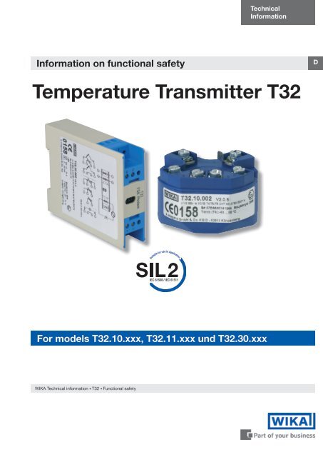
TechnicalInformationInformation on functional safetyD<strong>Temperature</strong> <strong>Transmitter</strong> <strong>T32</strong>For models <strong>T32</strong>.10.xxx, <strong>T32</strong>.11.xxx und <strong>T32</strong>.30.xxx<strong>WIKA</strong> Technical information • <strong>T32</strong> • Functional safety
<strong>Temperature</strong> <strong>Transmitter</strong> <strong>T32</strong>CPC 8000Contents1. General information on this handbook 31.1 Other applicable documentation 31.2 Abbreviations 31.3 Relevant standards 42. General safety information on SIL/SIS 42.1 Definition of Safety Integrity Level (SIL)) 42.2 Determination of Safety Integrity Level (SIL) 52.3 Definition of Safety Integrity System (SIS)) 62.3.1 Safety-related function 62.3.2 Failure possibilities 62.3.3 Proof test (T Proof ) 63. Device-specific safety information 73.1 Intended use 73.2 Device parameters / Write protection 73.3 Inadmissible safety-related use 83.4 Installation 83.5 Commissioning and periodic tests 83.6 Maintenance 93.7 Actions in case of errors 93.8 Safety-related variables 10Appendix – SIL Declaration of Conformity 11Appendix – exida.com, Management summary 12<strong>WIKA</strong> worldwide 1911188546 11/2006 GB<strong>WIKA</strong> Technical information • <strong>T32</strong> • Functional safety
<strong>Temperature</strong> <strong>Transmitter</strong> <strong>T32</strong>1. General information on this handbookThis booklet summarises the <strong>WIKA</strong> temperature transmitters <strong>T32</strong>.10 / <strong>T32</strong>.11 / <strong>T32</strong>.30 with firmwareversion 2.0.5 solely as part of a safety-related system. This documentation is valid with the documentationlisted in chapter 1.1. Please also note the safety instructions listed in the operating manual1.1 Other applicable documentationHeadversionRailversionHazardous AreaClassificationApproval – No. Manual Countries<strong>T32</strong>.1*.**2 <strong>T32</strong>.30.**2 II 1G EEx ia IICT4/T5/T6 DMT 99 ATEX E 007X 2383336 Europe<strong>T32</strong>.1*.**9 <strong>T32</strong>.30.**9 II 1G EEx nL/nA IIC T4/T5/T6 X -------- 2383336 Europe<strong>T32</strong>.1*.**6 <strong>T32</strong>.30.**6 Intrinsically safe C<strong>SA</strong> 1248412 2383336 Canada<strong>T32</strong>.1*.**8 -------- Intrinsically safe FM 3000040 2383336 U<strong>SA</strong><strong>T32</strong>.1*.**2 <strong>T32</strong>.30.**2 II 1G EEx ia IICT4/T5/T6 20003EC02CP028X INMETRO 2383336 Brasil<strong>T32</strong>.1*.**2 <strong>T32</strong>.30.**2 II 1G EEx ia IICT4/T5/T6 GYJ04431X, GYJ04432, NEPSI 2383336 China<strong>T32</strong>.1*.**9 -------- Ex nL/nA IIC T4~T6 GYJ05141U NEPSI 2383336 China1.2 AbbreviationsAcr. Designation DescriptionHFTHardware Fault ToleranceCapability of a functional unit to continue the execution of the demanded function inthe case of faults or anomalies,MTBF Mean Time Between Failures Mean interval between two failuresMTTRPFDPFD avgSILSFFT ProofMean Time To RepairProbability of Failure onDemandAverage Probability ofFailure on DemandSafety Integrity LevelSafe Failure FractionLife testing of the safetyfunctionMean interval between the occurrence of the failure in a device or system and itsrepairLikelihood of dangerous safety function failures occurring on demandAverage likelihood of dangerous safety function failures occurring on demandThe international standard IEC 61508 specifies four discrete safety integrity levels(SIL 1 to SIL 4). Each level corresponds to a specific probability range with respectto the failure of a safety function. The higher the integrity level of the safety-relatedsystem, the lower the likelihood of the demanded safety functions not occurring.Safe Failure Fraction summarises the proportion of failures which lead to a safestate, and the proportion of failures which will be detected by diagnostic measuresand lead to a defined safety action.Time interval between the functional test of the safety function.11188546 11/2006 GBXooY„X out of Y“Voting (e.g. 2oo3)Further relevant abbreviations are listed in the IEC 61508-4 standard.Classification and description of the safety-related system regarding redundancyand the selection procedure used. “Y” indicates how often the safety function iscarried out (redundancy). “X” determines how many channels must work properly.<strong>WIKA</strong> Technical information • <strong>T32</strong> • Functional safety
<strong>Temperature</strong> <strong>Transmitter</strong> <strong>T32</strong>CPC 80001.3 Relevant standardsAcr. English GermanIEC61508,Teil 1 bis 7Functional safety of electrical/electronic/programmable electronicsafety-related systemsTarget group: Manufacturers, Suppliersof DevicesSicherheitstechnische Systeme für die ProzessindustrieZielgruppe: Hersteller und Lieferanten von GerätenIEC61511,Teil 1Safety Instrumented Systems for theprocess industryTarget group: Safety InstrumentedSystems Designers, Integrators andUsersFunktionale Sicherheit sicherheitsbezogener elektrischer/elektronischer/programmierbarer elektronischer SystemeZielgruppe: Planer, Errichter Nutzer2. General safety information on SIL/SIS2.1 Definition of Safety Integrity Level (SIL)IEC 61508 defines four Safety Integrity Levels (SIL). Each SIL-Level corresponds to the statisticalprobability of the failure of a safety-related system. (IEC 61508-4, part .5.6). The higher the SIL ofthe safety-related system, the higher the probability that the safety-related system will work on demandand the higher the risk reduction. Or described differently, the higher the safety integrity level of thesafety-related system, the lower the probability that the safety-related system won’t work.The achievable safety integrity level depends on the following safety-related characteristics:• This value depends on the value of T Proof between the functional test of the safety-related system.• Hardware Fault Tolerance - HFT (Hardware Fault Tolerance - HFT)• Safe Failure Fraction – SFF (Safe Failure Fraction – SFF)The following table shows the interrelation of the safety integrity level (SIL) with the whole safetyrelatedsystem (IEC 61508-1, chapter 7.6.2.9).Safety IntegrityLevel (SILLow demand mode ofoperation (PFD avg)(Average probability of failureto perform its design function ondemand)High demand orcontinuous mode ofoperation (PFD avg)(Probability of a dangerous failureper hour)Risk Reduction Factor4 ≥ 10 -5 to ≥ 10 -4 ≥ 10 -9 to ≥ 10 -8 100000 to 100003 ≥ 10 -4 to ≥ 10 -3 ≥ 10 -8 to ≥ 10 -7 10000 to 10002 ≥ 10 -3 to ≥ 10 -2 ≥ 10 -7 to ≥ 10 -6 1000 to 1001 ≥ 10 -2 to ≥ 10 -1 ≥ 10 -6 to ≥ 10 -5 100 to 1011188546 11/2006 GB<strong>WIKA</strong> Technical information • <strong>T32</strong> • Functional safety
<strong>Temperature</strong> <strong>Transmitter</strong> <strong>T32</strong>CPC 80002.3 Definition of Safety Integrity System (SIS)PFDavg is the average probability of failure on demand of the safety-related protection system, whichis the safety integrity failure measure for safety-related protection systems operating in a low demandmode of operation;Sensor(TempTrans)Logic-System(e.g. PLC)Actuator(e.g. valve)≤ 35 % ≤ 15 % ≤ 50 %2.3.1 Safety-related functionThe analogue signal is transmitted to a series-connected logic unit, e.g. a PLC or an alarm contact,where it is monitored as to whether it exceeds a maximum value or drops below a minimum value.The logic unit controls the process e.g. with a signal to an actuator (e.g. valve).2.3.2 , Failure possibilitiesSafe Failure (λsd und λsu), (IEC 61508-4, part 3.6.8):A safe failure occurs if the measuring system switches into the safe state or the error mode withoutdemand from the process.Dangerous Failure (λdd) + λdu)), (IEC 61508-4, part 3.6.7):A dangerous failure occurs if the measuring system switches into a dangerous or functionallyinoperable condition.Dangerous Undetected Failure (λdu)):A dangerous undetected failure occurs if the measuring system does not switch into a safecondition or into the error mode on a demand from the process.2.3.3 Proof test (T Proof )According to IEC 61508-4, part 3.8.5, T Proof is defined as periodic tests for exposing errors in asafety-related system11188546 11/2006 GB<strong>WIKA</strong> Technical information • <strong>T32</strong> • Functional safety
<strong>Temperature</strong> <strong>Transmitter</strong> <strong>T32</strong>3. Device-specific safety information3.1 Intended useThe instrument is a universal, configurable transmitter for resistance thermometers (RTD), thermocouples(TC) as well as resistance and voltage calibration sources. The temperature transmitterconverts a resistance or voltage value into a proportional current signal between 3.8mA and 20.5mA.The analogue signal is transmitted to a series-connected logic unit, e.g. a PLC or an alarm contact,where it is monitored as to whether it exceeds a maximum value or drops below a minimum value.The temperature transmitter monitors the connected sensor and the internal hardware for errors.If an error is detected, the transmitter generates both a digital error signal via HART®-Protocol andan analogue signal at the defined output current (error current for fail low / fail high).Note: HART® Information must not be used for safety-related operations.The <strong>T32</strong> generates an error current for the following error conditions.• Sensor burn-out• Sensor short-circuit (only for resistance sensor)• Internal hardware error• Sensor measuring range exceeded or below sensor measuring range• Invalid cold-junction compensation temperature (for thermocouples)For the error current, the following conditions are defined by NAMUR NE43:• error current, Fail Low: < 3,6 mA (Downscale)• error current, Fail High: < 21,5 mA (Upscale)If the transmitter delivers the “fail high” or “fail low output current, the user must assume there is afailure in the system.The logic unit must be capable of recognising the Fail-High error current (adjustable from 21...22.5 mA)as well as the Fail-Low error current (3.6 mA). The logic unit must give an appropriate alarm signal.A measured value is to be assumed in the range of the output current of .8 mA < x < 20,5 mA .The transmitter fulfils, in particular, the requirements for:• functional safety according to IEC 61508/IEC 61511-1• explosion protection (depending on the instrument version)• electromagnetic compatibility according to EN 61326 and NAMUR recommendation NE 21• analogue output error-signalling according to NAMUR recommendation NE 43• Sensor burnout signalling according to NAMUR recommendation NE 89.3.2 Device parameters / Write protection11188546 11/2006 GBBecause the process and equipment conditions affect the safety of the whole measuring system, theinstrument parameters have to be set according to the application needs.The specified limits must be followed; the <strong>T32</strong>’s specifications must not be exceeded.To protect against inadvertent and/or unauthorised changes in the configuration, alterable parametersmust be write-protected (password activated).<strong>WIKA</strong> Technical information • <strong>T32</strong> • Functional safety
<strong>Temperature</strong> <strong>Transmitter</strong> <strong>T32</strong>CPC 8000The write protection (password) can be used with the following configuration tools:• <strong>WIKA</strong>_<strong>T32</strong> Configuration-Software• AMS• SIMATIC PDM• DTM (Version: DTM Betaversion V1.0.2 January 2003) in combination with FDT/DTM-Standarduser software, e.g PACTware TM• HART®- Handterminal FC375, FC275• and further tools (this list is regulary enhanced)3.4 Inadmissible safety-related useMeasured value transmission via HART® protocol and the HART® “Multidrop-network” can only beused for setup, calibration, and diagnostic purposes, not during normal safety-related operation.3.5 InstallationFor installation and mounting instructions please refer to the operating instructions.3.6 Commissioning and periodic testsFunction tests are intended to demonstrate the correct function of the whole safety-related system,including all instruments (Sensor, Logic unit, and actuator). Therefore the operability and error currentof the <strong>T32</strong>, as a part of the sensor, must be tested both during commissioning and at reasonableintervals.Both the nature of the tests as well as the chosen intervals are the responsibility of the user. The intervalsare set according to the PFDavg values used. (Please refer to the FMEDA report). Usually T proof isone year or less.The following tests should only be carried out with write-protection activated, in order toprevent accidental configuration changes.Recommended tests:• Simulate a sensor-break and a sensor burnout (sensor burnout only for RTD sensors) andcheck the response of the transmitter (error current according to the chosen configuration).• If the temperature sensors are simulated, the following should apply: The input signal must begenerated for the start, middle and end signal of the configured sensor and measuring range.The corresponding output signal must be monitored (start, middle, span). Recommended tools forsensor simulation are resistance decades or voltage simulators.• The sensor measuring ranges must be tested both over- and under-range(e.g. Pt100: -200 < x < 1000°C) and the response of the transmitter checked (error currentaccording to configuration).• The configuration of the transmitter should be altered using a suitable configuration tool (e.g.<strong>WIKA</strong> Configuration Software) and the response checked. The transmitter must respond with anerror, due to the activated write-protection.In some special cases the transmitter logic unit connection can be tested using the “Simulation“ withinthe transmitter (i.e. without any sensor or sensor simulation connected). The desired output current ofthe transmitter, between 4 mA and 20 mA, can be simulated using the configuration tools described inChapter .. To use this feature, the write-protection must be disabled, which means an additionalrisk. The methods and procedures for these tests must be documented, as must the test results.If the outcome of the function test is negative, the whole system must be shut down. The process mustbe put into a safe condition using appropriate procedures.11188546 11/2006 GB<strong>WIKA</strong> Technical information • <strong>T32</strong> • Functional safety
<strong>Temperature</strong> <strong>Transmitter</strong> <strong>T32</strong>3.7 MaintenanceThe transmitter <strong>T32</strong> is maintenance free. The electrical components of the transmitter are mounted in aplastic case and completely encapsulated. The transmitters therefore have no devices which could bechanged or repaired.3.8 Actions in case of errorsThe cause of malfunctions as well as hints for resolving them are described in the operating instructions.If malfunctions cannot be resolved, the whole measuring system must be shut down. The processmust be put into a safe condition using appropriate procedures.Defective instruments must be marked to prevent inadvertent re-use.Send the faulty instruments back to <strong>WIKA</strong>, along with a description of the cause of the fault. Please usethe Product Return sheet, which can be found at www.wika.de / Service / retoure.<strong>WIKA</strong> Alexander Wiegand GmbH & Co. KGAlexander Wiegand Straße63911 KlingenbergTel: 09372 / 132-0www.wika.de11188546 11/2006 GB<strong>WIKA</strong> Technical information • <strong>T32</strong> • Functional safety
<strong>Temperature</strong> <strong>Transmitter</strong> <strong>T32</strong>CPC 80003.9 Safety-related variablesThe failure rates of the electronics were determined using FMEDA according to IEC61508. The failurerates used in this analysis are the basic failure rates from the Siemens standard SN 29500.The following assumptions have been made:• All modules are operated in the Low Demand Mode of operation.• External power supply failure rates are not included.• The logic unit must be capable of recognising the Fail-High error current (adjustable from21...22.5 mA) as well as the Fail-Low error current (3.6 mA) and must give an appropriate alarmsignal.• The values for SFF und PFD avg obtained from the FMEDA-report have been used.• HART®-protocol is only used for setup, calibration, and diagnostic purposes, not duringsafety-related normal operation.• The mean ambient temperature during the period of operation is 40°C.• The environmental conditions / stress levels are average for an industrial environment• The temperature transmitter is locked against unintentional and unauthorised change/use(password protected).• The repair time after a safe failure is 8 hours.Safety-related figuresExamination for a type B component, with low demand mode and a Hardware Fault Tolerance(HFT) of 0.<strong>T32</strong>.**.***(1)<strong>T32</strong>.**.***with thermocoupleconnected (4)<strong>T32</strong>.**.***with 4-wire RTD connected(4)<strong>T32</strong>.**.***with 2/3-wire RTDconnected (4)(TC)(4-wire)(2-, 3-wire)SFFPFD avgλ sdλ suλ ddλ duSafe FailureFractionAverage Probalilityof dangerousFailure on demandFailure rate λ safefailure detectedFailure rate λ safefailure undetectedFailure rate λdangerous failuredetectedFailure rate λdangerous failureundetected> 63 % > 91,75 % > 90,95 % > 76,21 %9,4-E04 (2) 2,02-E03 (2) 1,02-E03 (2) 2,69-E03 (2)Note (3) 4.929 FIT 2.158 FIT 1.775 FITNote (3) 135 FIT 133 FIT 135 FITNote (3) 60 FIT 60 FIT 60 FITNote (3) 461 FIT 234 FIT 615 FIT((1) Without examination of the reliability sensor data.(2) PFDavg is valid only for the TProof – interval (1 Year), after a recurring function test was carried out(3) Detailed values (depending on the transmitter configuration) are given in the FMEDA-report(4) Examination using generic low stress reliability data for the temperature sensor.11188546 11/2006 GB10<strong>WIKA</strong> Technical information • <strong>T32</strong> • Functional safety
<strong>Temperature</strong> <strong>Transmitter</strong> <strong>T32</strong>Appendix - SIL Delaration of Conformity11188546 11/2006 GB<strong>WIKA</strong> Technical information • <strong>T32</strong> • Functional safety11
<strong>Temperature</strong> <strong>Transmitter</strong> <strong>T32</strong>CPC 8000Appendix - exida.com, Management summaryFailure Modes, Effects and Diagnostic AnalysisProject:Digital <strong>Temperature</strong> <strong>Transmitter</strong> <strong>T32</strong> HARTCustomer:<strong>WIKA</strong> – Alexander Wiegand GmbH & Co. KGKlingenbergGermanyContract No.: <strong>WIKA</strong> 02/3-10Report No.: <strong>WIKA</strong> 02/3-10 R002Version V2, Revision R1.2, February 2005Stephan AschenbrennerThe document was prepared using best effort. The authors make no warranty of any kind and shall not be liable inany event for incidental or consequential damages in connection with the application of the document.© All rights on the format of this technical report reserved.11188546 11/2006 GB12<strong>WIKA</strong> Technical information • <strong>T32</strong> • Functional safety
<strong>Temperature</strong> <strong>Transmitter</strong> <strong>T32</strong>Management summaryThis report summarizes the results of the hardware assessment carried out on the Digital<strong>Temperature</strong> <strong>Transmitter</strong> <strong>T32</strong> HART with firmware version 2.0.4 or 2.0.5. Table 1 gives anoverview of the different types that belong to the considered Digital <strong>Temperature</strong> <strong>Transmitter</strong><strong>T32</strong> HART.The hardware assessment consists of a Failure Modes, Effects and Diagnostics Analysis(FMEDA). A FMEDA is one of the steps taken to achieve functional safety assessment of adevice per IEC 61508. From the FMEDA, failure rates are determined and consequently theSafe Failure Fraction (SFF) is calculated for the device. For full assessment purposes allrequirements of IEC 61508 must be considered.Table 1: Version overview<strong>T32</strong>.10 Digital <strong>Temperature</strong> <strong>Transmitter</strong>, head mounted (standard)<strong>T32</strong>.11 Digital <strong>Temperature</strong> <strong>Transmitter</strong>, head mounted (high ambient temperature stability)<strong>T32</strong>.30 Digital <strong>Temperature</strong> <strong>Transmitter</strong>, rail mounted (standard)For safety applications only the 4..20 mA output was considered.The failure rates used in this analysis are the basic failure rates from the Siemens standardSN 29500.According to table 2 of IEC 61508-1 the average PFD for systems operating in low demandmode has to be ≥10 -2 to < 10 -1 for SIL 1 safety functions and ≥10 -3 to < 10 -2 for SIL 2 safetyfunctions. A generally accepted distribution of PFD AVG values of a SIF over the sensor part, logicsolver part, and final element part assumes that 35% of the total SIF PFD AVG value is caused bythe sensor part.For a SIL 1 application the total PFD AVG value of the SIF should be smaller than 1,00E-01,hence the maximum allowable PFD AVG value for the sensor assembly consisting of <strong>T32</strong> and athermocouple or RTD supplied with <strong>T32</strong> would then be 3,50E-02.For a SIL 2 application the total PFD AVG value of the SIF should be smaller than 1,00E-02,hence the maximum allowable PFD AVG value for the sensor assembly consisting of <strong>T32</strong> and athermocouple or RTD supplied with <strong>T32</strong> would then be 3,50E-03.The Digital <strong>Temperature</strong> <strong>Transmitter</strong> <strong>T32</strong> HART is considered to be a Type B 1 component witha hardware fault tolerance of 0.For Type B components the SFF has to be between 60% and 90% for SIL 1 (sub-) systems andbetween 90% and 99% for SIL 2 (sub-) systems with a hardware fault tolerance of 0 accordingto table 2 of IEC 61508-2.Assuming that a connected logic solver can detect both over-range (fail high) and under-range(fail low), high and low failures can be classified as safe detected failures or dangerous detectedfailures depending on whether the Digital <strong>Temperature</strong> <strong>Transmitter</strong> <strong>T32</strong> HART is used in anapplication for “low level monitoring” (MIN), “high level monitoring” (MAX) or “range monitoring”.For these applications the following tables show how the above stated requirements are fulfilledfor the worst case configuration of the Digital <strong>Temperature</strong> <strong>Transmitter</strong> <strong>T32</strong> HART.11188546 11/2006 GB1 Type B component: “Complex” component (using micro controllers or programmable logic); for details see7.4.3.1.3 of IEC 61508-2.© exida.com GmbH wika 02-3-10 r002 v2 r1.2, February 8, 2005Stephan Aschenbrenner Page 2 of 5<strong>WIKA</strong> Technical information • <strong>T32</strong> • Functional safety13
<strong>Temperature</strong> <strong>Transmitter</strong> <strong>T32</strong>CPC 8000Table 2: Summary for <strong>T32</strong> (worst case configuration) – Failure ratesFailure category (Failure rates in FIT)Fail High (detected by the logic solver)Fail detected (int. diag.) 137Fail high (inherently) 38Fail Low (detected by the logic solver)Fail detected (int. diag.) 137Fail-safe state =“fail high”175Fail low (inherently) 60 60Fail-safe state =“fail low”Fail Dangerous Undetected 215 215No Effect 135 135MTBF = MTTF + MTTR 195 years 195 years38197<strong>Transmitter</strong> configured fail-safe state = “fail high” – Failure rates according to IEC 61508Failure Categories λ sd λ su λ dd λ du SFF DC S2DC D ²λ low = λ sdλ high = λ dd60 FIT 135 FIT 175 FIT 215 FIT 63% 30% 44%λ low = λ ddλ high = λ sd175 FIT 135 FIT 60 FIT 215 FIT 63% 56% 21%λ low = λ sdλ high = λ sd235 FIT 135 FIT 0 FIT 215 FIT 63% 63% 0%<strong>Transmitter</strong> configured fail-safe state = “fail low” – Failure rates according to IEC 61508Failure Categories λ sd λ su λ dd λ du SFF DC S ² DC D ²λ low = λ sdλ high = λ dd197 FIT 135 FIT 38 FIT 215 FIT 63% 59% 15%λ low = λ ddλ high = λ sd38 FIT 135 FIT 197 FIT 215 FIT 63% 21% 47%λ low = λ sdλ high = λ sd235 FIT 135 FIT 0 FIT 215 FIT 63% 63% 0%It is important to realize that the “don’t care” failures are included in the “safe undetected” failurecategory according to IEC 61508. Note that these failures on its own will not affect systemreliability or safety, and should not be included in spurious trip calculations.2 DC means the diagnostic coverage (safe or dangerous) of the safety logic solver for the Digital<strong>Temperature</strong> <strong>Transmitter</strong> <strong>T32</strong> HART.© exida.com GmbH wika 02-3-10 r002 v2 r1.2, February 8, 2005Stephan Aschenbrenner Page 3 of 511188546 11/2006 GB14<strong>WIKA</strong> Technical information • <strong>T32</strong> • Functional safety
<strong>Temperature</strong> <strong>Transmitter</strong> <strong>T32</strong>Table 3: Summary for <strong>T32</strong> (worst case configuration) – PFD AVG valuesT[Proof] = 1 year T[Proof] = 5 years T[Proof] = 10 yearsPFD AVG = 9,41E-04 PFD AVG = 4,69E-03 PFD AVG = 9,36E-03A complete temperature sensor assembly consisting of <strong>T32</strong> and a closely coupledthermocouple or cushioned RTD supplied with <strong>T32</strong> can be modeled by considering a seriessubsystem where a failure occurs if there is a failure in either component. For such a system,failure rates are added.Section 5.5 gives typical failure rates and failure distributions for thermocouples and RTDswhich were the basis for the following tables.Assuming that <strong>T32</strong> is programmed to drive its output high on detected failures of thethermocouple or RTD (λ low = λ dd , λ high = λ sd ), the failure rate contribution or the PFD AVG value forthe thermocouple or RTD in a low stress environment is as follows:Table 4: Summary for the sensor assembly <strong>T32</strong> / thermocouple in low stress environmentT[Proof] = 1 year T[Proof] = 5 years T[Proof] = 10 years SFFPFD AVG = 2,02E-03 PFD AVG = 1,01E-02 PFD AVG = 2,02E-02 > 91%λ sd = 4929 FITλ su = 135 FITλ dd = 60 FITλ du = 461 FITTable 5: Summary for the sensor assembly <strong>T32</strong> / 4-wire RTD in low stress environmentT[Proof] = 1 year T[Proof] = 5 years T[Proof] = 10 years SFFPFD AVG = 1,02E-03 PFD AVG = 5,12E-03 PFD AVG = 1,02E-02 > 90%λ sd = 2158 FITλ su = 133 FITλ dd = 60 FITλ du = 234 FITTable 6: Summary for the sensor assembly <strong>T32</strong> / 2/3-wire RTD in low stress environmentT[Proof] = 1 year T[Proof] = 5 years T[Proof] = 10 years SFFPFD AVG = 2,69E-03 PFD AVG = 1,35E-02 PFD AVG = 2,69E-02 > 76%λ sd = 1775 FITλ su = 135 FITλ dd = 60 FITλ du = 615 FIT11188546 11/2006 GB© exida.com GmbH wika 02-3-10 r002 v2 r1.2, February 8, 2005Stephan Aschenbrenner Page 4 of 5<strong>WIKA</strong> Technical information • <strong>T32</strong> • Functional safety15
<strong>Temperature</strong> <strong>Transmitter</strong> <strong>T32</strong>The boxes marked in yellow ( ) mean that the calculated PFD AVG values are within theallowed range for SIL 2 according to table 2 of IEC 61508-1 but do not fulfill the requirement tonot claim more than 35% of this range, i.e. to be better than or equal to 3,50E-03. The boxesmarked in green ( ) mean that the calculated PFD AVG values are within the allowed range forSIL 2 according to table 2 of IEC 61508-1 and table 3.1 of ANSI/I<strong>SA</strong>–84.01–1996 and do fulfillthe requirement to not claim more than 35% of this range, i.e. to be better than or equal to3,50E-03. The boxes marked in red ( ) mean that the calculated PFD AVG values do not fulfillthe requirement for SIL 2 according to table 2 of IEC 61508-1.Where the Safe Failure Fraction (SFF) is between 60% and 90% the SIL 1 architecturalconstraints requirements of table 3 of IEC 61508-2 for Type B subsystems with a HardwareFault Tolerance (HFT) of 0 are fulfilled.Where the Safe Failure Fraction (SFF) is above 90% the SIL 2 architectural constraintsrequirements of table 3 of IEC 61508-2 for Type B subsystems with a Hardware Fault Tolerance(HFT) of 0 are fulfilled.The hardware assessment has shown that the Digital <strong>Temperature</strong> <strong>Transmitter</strong> <strong>T32</strong> HARTwith 4..20 mA output has a PFD AVG within the allowed range for SIL 1 according to table 2of IEC 61508-1 and table 3.1 of ANSI/I<strong>SA</strong>–84.01–1996 and a Safe Failure Fraction (SFF) ofmore than 63%.A user of the Digital <strong>Temperature</strong> <strong>Transmitter</strong> <strong>T32</strong> HART can utilize these failure rates alongwith the failure rates for the temperature sensing device in a probabilistic model of a safetyinstrumented function (SIF) to determine suitability in part for safety instrumented system (SIS)usage in a particular safety integrity level (SIL). A full table of failure rates for different operatingconditions is presented in section 5.1 to 5.4 along with all assumptions and temperature sensingdevice data.11188546 11/2006 GB© exida.com GmbH wika 02-3-10 r002 v2 r1.2, February 8, 2005Stephan Aschenbrenner Page 5 of 5<strong>WIKA</strong> Technical information • <strong>T32</strong> • Functional safety16
<strong>Temperature</strong> <strong>Transmitter</strong> <strong>T32</strong>CPC 80001 Purpose and ScopeGenerally three options exist when doing an assessment of sensors, interfaces and/or finalelements.Option 1: Hardware assessment according to IEC 61508Option 1 is a hardware assessment by exida.com according to the relevant functional safetystandard(s) like DIN V VDE 0801, IEC 61508 or EN 954-1. The hardware assessment consistsof a FMEDA to determine the fault behavior and the failure rates of the device, which are thenused to calculate the Safe Failure Fraction (SFF) and the average Probability of Failure onDemand (PFD AVG ).This option for pre-existing hardware devices shall provide the safety instrumentation engineerwith the required failure data as per IEC 61508 / IEC 61511 and does not consist of anassessment of the software development processOption 2: Hardware assessment with proven-in-use consideration according to IEC 61508 /IEC 61511Option 2 is an assessment by exida.com according to the relevant functional safety standard(s)like DIN V VDE 0801, IEC 61508 or EN 954-1. The hardware assessment consists of a FMEDAto determine the fault behavior and the failure rates of the device, which are then used tocalculate the Safe Failure Fraction (SFF) and the average Probability of Failure on Demand(PFD AVG ). In addition this option consists of an assessment of the proven-in-use documentationof the device and its software including the modification process.This option for pre-existing programmable electronic devices shall provide the safetyinstrumentation engineer with the required failure data as per IEC 61508 / IEC 61511 and justifythe reduced fault tolerance requirements of IEC 61511 for sensors, final elements and other PEfield devices.Option 3: Full assessment according to IEC 61508Option 3 is a full assessment by exida.com according to the relevant application standard(s)like IEC 61511 or EN 298 and the necessary functional safety standard(s) like DIN V VDE 0801,IEC 61508 or EN 954-1. The full assessment extends option 1 by an assessment of all faultavoidance and fault control measures during hardware and software development.This option is most suitable for newly developed software based field devices andprogrammable controllers to demonstrate full compliance with IEC 61508 to the end-user.This assessment shall be done according to option 1.This document shall describe the results of the assessment carried out on the Digital<strong>Temperature</strong> <strong>Transmitter</strong> <strong>T32</strong> HART with firmware version 2.0.4 or 2.0.5. Table 1 gives anoverview of the series and explains the differences between the different types.It shall be assessed whether the transmitter meets the average Probability of Failure onDemand (PFD AVG ) requirements and the architectural constraints for SIL 1 sub-systemsaccording to IEC 61508. It does not consider any calculations necessary for proving intrinsicsafety.© exida.com GmbH wika 02-3-10 r002 v2 r1.2, February 8, 2005Stephan Aschenbrenner Page 2 of 211188546 11/2006 GB17<strong>WIKA</strong> Technical information • <strong>T32</strong> • Functional safety
<strong>Temperature</strong> <strong>Transmitter</strong> <strong>T32</strong><strong>WIKA</strong> worldwideEuropeAustria<strong>WIKA</strong> MessgerätevertriebUrsula WiegandGmbH & Co. KG1230 WienPhone: (+43) 1-86 91 631Fax: (+43) 1-86 91 634E-mail: info@wika.atwww.wika.atBenelux<strong>WIKA</strong> Benelux6101 WX EchtPhone: (+31) 475-535 500Fax: (+31) 475-535 446E-mail: info@wika.nlwww.wika.nlBulgaria<strong>WIKA</strong> Bulgaria EOOD1309 SofiaPhone: (+359) 2 82138-10Fax: (+359) 2 82138-13E-mail: t.antonov@wika.bgFinland<strong>WIKA</strong> Finland Oy00210 HelsinkiPhone: (+358) 9-682 49 20Fax: (+358) 9-682 49 270E-mail: info@wika.fiwww.wika.fiFrance<strong>WIKA</strong> Instruments s.a.r.l.95610 Eragny-sur-OisePhone: (+33) 1-34 30 84 84Fax: (+33) 1-34 30 84 94E-mail: info@wika.frwww.wika.frGermany<strong>WIKA</strong>Alexander WiegandGmbH & Co. KG63911 KlingenbergPhone: (+49) 93 72-13 20Fax: (+49) 93 72-13 24 06E-mail: info@wika.dewww.wika.deItaly<strong>WIKA</strong> Italiana SRL20020 Arese (Milano)Phone: (+39) 02-93 86 11Fax: (+39) 02-93 86 174E-mail: info@wika.itwww.wika.itPolandKujawska Fabryka Manometrow-KFM S.A.87-800 WloclawekPhone: (+48) 542 30 11 00Fax: (+48) 542 30 11 01E-mail: info@manometry.com.plwww.manometry.com.plRomania<strong>WIKA</strong> Instruments S.R.L.Bucuresti, Sector 5Phone: (+40) 21-456 31 38Fax: (+40) 21-456 31 37E-mail: m.anghel@wika.roRussiaZAO „<strong>WIKA</strong> MERA“127015 MoscowPhone: (+7) 495-786 21 25Fax: (+7) 495-786 21 23E-mail: info@wika.ruwww.wika.ruSerbia<strong>WIKA</strong> Merna Tehnika d.o.o.11060 BeogradPhone: (+381) 11 27 63 722Fax: (+381) 11 75 36 74E-mail: info@wika.co.yuwww.wika.co.yuSpainInstrumentos <strong>WIKA</strong>, S.A.08280 Sabadell (Barcelona)Phone: (+34) 90-290 25 77Fax: (+34) 93-393 86 66E-mail: info@wika.eswww.wika.esSwitzerlandMANOMETER AG6285 HitzkirchPhone: (+41) 41-919 72 72Fax: (+41) 41-919 72 73E-mail: info@manometer.chwww.manometer.chUkraine<strong>WIKA</strong> Pribor GmbH83016 DonetskPhone: (+38) 062 345 34 16Fax: (+38) 062 345 34 16E-mail: info@wika.donetsk.uawww.wika.donetsk.uaUnited Kingdom<strong>WIKA</strong> Instruments LtdMerstham, Redhill RH13LGPhone: (+44) 17 37 64 40 08Fax: (+44) 17 37 64 44 03E-mail: info@wika.co.ukwww.wika.co.ukNorth AmericaCanada<strong>WIKA</strong> Instruments Ltd.Head OfficeEdmonton, Alberta, T6N 1C8Phone: (+1) 780-463 70 35Fax: (+1) 780-462 00 17E-mail: info@wika.cawww.wika.caMexicoInstrumentos <strong>WIKA</strong> Mexico S.A.de C.V.01219 Mexico D.F.Phone: (+52) 555 020 53 00Fax: (+52) 555 020 53 01E-Mail ventas@wika.com.mxwww.wika.com.mxU<strong>SA</strong><strong>WIKA</strong> Instrument CorporationLawrenceville, GA 30043Phone: (+1) 770-513 82 00Fax: (+1) 770-338 51 18E-mail: info@wika.comwww.wika.comSouth America<strong>Argentina</strong><strong>WIKA</strong> <strong>Argentina</strong> S.A.Buenos AiresPhone: (+54-11) 4730 18 00Fax: (+54-11) 4761 00 50E-mail: info@wika.com.arwww.wika.com.arBrazil<strong>WIKA</strong> do Brasil Ind. e Com.Ltda.CEP 18560-000 Iperó - SPPhone: (+55) 15-3266 16 55Fax: (+55) 15-3266 16 50E-mail: marketing@wika.com.brwww.wika.com.brAfrica/Middle EastEgypt<strong>WIKA</strong> Alexander WiegandGmbH & Co. KGMakram EbaidNasr City, CairoPhone: (+20) 2 - 273 31 40Fax: (+20) 2 - 273 31 40E-mail: ahmed.azab@wika.deIran<strong>WIKA</strong> Instrumentation Pars(KFZ) Ltd.Anahita Tower, TehranPhone: (+98-21) 8878 3514-17Fax: (+98-21) 8887 8593E-mail: info@wika.irwww.wika.irSouth Africa<strong>WIKA</strong> Instruments (Pty.) Ltd.Gardenview, Johannesburg2047Phone: (+27) 11-621 00 00Fax: (+27) 11-621 00 59E-mail: sales@wika.co.zawww.wika.co.zaUnited Arab Emirates<strong>WIKA</strong> Middle East FZEJebel Ali, DubaiPhone: (+971) 4 - 883 90 90Fax: (+971) 4 - 883 91 98E-mail: wikame@emirates.net.aeAsiaChina<strong>WIKA</strong> International Trading(Shanghai) Co., Ltd.200001 ShanghaiPhone: (+86) 21 - 53 85 25 73Fax: (+86) 21 - 53 85 25 75E-mail: wikash@online.sh.cnwww.wika.com.cnIndia<strong>WIKA</strong> Instruments India Pvt. Ltd.Village Kesnand, WagholiPune - 412 207Phone: (+91) 20 - 27 05 29 01Fax: (+91) 20 - 27 05 19 25E-mail: sales@wika.co.inwww.wika.co.inJapan<strong>WIKA</strong> Japan K. K.Tokyo 105-0023Phone: (+81) 3-54 39 66 73Fax: (+81) 3-54 39 66 74E-mail: t-shimane@wika.co.jpKazakhstanTOO <strong>WIKA</strong> Kazakhstan050050 AlmatyPhone: (+7) 32 72 33 08 48Fax: (+7) 32 72 78 99 05E-mail:wika-kazakhstan@nursat.kzKorea<strong>WIKA</strong> Korea Ltd.Seoul 153-023Phone: (+82) 2 - 8 69 05 05Fax: (+82) 2 - 8 69 05 25E-mail: info@wika.co.krMalaysia<strong>WIKA</strong> Instrumentation (M)Sdn. Bhd.Selangor Darul EhsanPhone: (+60) 3 - 56 36 88 58Fax: (+60) 3 - 56 36 90 72E-mail: info@wika.com.mywww.wika.com.mySingapore<strong>WIKA</strong> Instrumentation Pte. Ltd.569625 SingaporePhone: (+65) 68 44 55 06Fax: (+65) 68 44 55 07E-mail: info@wika.com.sgwww.wika.com.sgTaiwan<strong>WIKA</strong> Instrumentation TaiwanLtd.Pinjen, TaoyuanPhone: (+886) 034 20 60 52Fax: (+886) 034 90 00 80E-mail: info@wika.com.twwww.wika.com.twAustraliaAustralia<strong>WIKA</strong> Australia Pty. Ltd.Rydalmere, NSW 2116Phone: (+61) 2 - 88 45 52 22Fax: (+61) 2 - 96 84 47 67E-mail: sales@wika.com.auwww.wika.com.au11188546 11/2006 GB<strong>WIKA</strong> Technical information • <strong>T32</strong> • Functional safety18
<strong>WIKA</strong> Alexander Wiegand GmbH & Co. KGAlexander-Wiegand-Straße 3063911 Klingenberg · GermanyPhone (+49) 93 72/132-0Fax (+49) 93 72/132-406E-Mail info@wika.dewww.wika.de