1. analisi dinamica di un sistema di trasmissione in corrente continua
1. analisi dinamica di un sistema di trasmissione in corrente continua
1. analisi dinamica di un sistema di trasmissione in corrente continua

You also want an ePaper? Increase the reach of your titles
YUMPU automatically turns print PDFs into web optimized ePapers that Google loves.
R l +sL l<br />
R l +sL l<br />
2 2 sL s R i<br />
V cosα<br />
or<br />
R r sL s<br />
sC l<br />
V dr<br />
I dr<br />
1<br />
I <strong>di</strong><br />
V <strong>di</strong><br />
V<br />
oi<br />
cosα<br />
i<br />
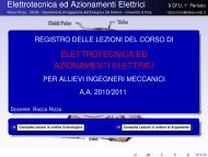
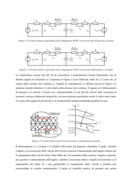
Figura <strong>1.</strong>2 Circuito elettrico equivalente <strong>di</strong> <strong>un</strong> collegamento HVDC con <strong>in</strong>verter f<strong>un</strong>zionante ad α costante<br />
R l +sL l<br />
R l +sL l<br />
2 2 sL s -R i<br />
V cosα<br />
or<br />
R r sL s<br />
sC l<br />
V dr<br />
I dr<br />
1<br />
I <strong>di</strong><br />
V <strong>di</strong><br />
V cosγ<br />
oi<br />
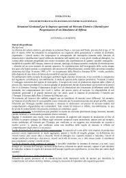
Figura <strong>1.</strong>3 Circuito elettrico equivalente <strong>di</strong> <strong>un</strong> collegamento HVDC con <strong>in</strong>verter f<strong>un</strong>zionante a γ costante<br />
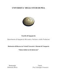
La caratteristica esterna lato DC <strong>di</strong> <strong>un</strong> convertitore a commutazione forzata f<strong>un</strong>zionante con <strong>un</strong><br />
def<strong>in</strong>ito angolo <strong>di</strong> accensione α è riportata <strong>in</strong> Figura <strong>1.</strong>4 per <strong>di</strong>fferenti valori <strong>di</strong> α. È noto che, al<br />
variare della <strong>corrente</strong> lato cont<strong>in</strong>ua I d , l’angolo <strong>di</strong> commutazione u, def<strong>in</strong>ito ancora <strong>in</strong> Figura <strong>1.</strong>4,<br />
aumenta, facendo <strong>di</strong>m<strong>in</strong>uire il valor me<strong>di</strong>o della tensione lato cont<strong>in</strong>ua. Il legame tra l’abbassamento<br />
<strong>di</strong> tensione e la <strong>corrente</strong> è l<strong>in</strong>eare ed è schematizzabile, ai soli f<strong>in</strong>i del calcolo della variazione <strong>di</strong><br />
tensione e non per valutazioni energetiche, con <strong>un</strong>a resistenza equivalente avente il valore sopra citato.<br />
Al variare dell’angolo <strong>di</strong> accensione α, le caratteristiche traslano rimanendo parallele tra loro.<br />
V d<br />
-V i<br />
V cosα<br />
o 1<br />
α<br />
F<strong>un</strong>zionam. da<br />
raddrizzatore<br />
V cosα<br />
o 2<br />
α crescenti<br />
V cosα<br />
o 3<br />
I d<br />
α<br />
F<strong>un</strong>zionam.<br />
da <strong>in</strong>vertitore<br />
u<br />
γ<br />
β<br />
β=π−α<br />
γ=π−(α+u)<br />
V<br />
o<br />
cosα<br />
4<br />
-V o cosγ 2<br />
-V<br />
o<br />
cosγ<br />
1<br />
γ crescenti<br />
Figura <strong>1.</strong>4 Caratteristiche esterne del convertitore a commutazione naturale<br />
Il f<strong>un</strong>zionamento a γ costante è il risultato dell’azione del preposto controllore il quale, variando<br />
l’angolo α i <strong>di</strong> accensione delle valvole dell’<strong>in</strong>verter assicura il mantenimento dell’angolo m<strong>in</strong>imo per<br />
lo spengimento delle valvole stesse. Dato <strong>in</strong>fatti che, all’aumentare della <strong>corrente</strong>, l’angolo u aumenta,<br />
per garantire il mantenimento dell’angolo γ m<strong>in</strong>imo è necessario ridurre l’angolo <strong>di</strong> accensione α. Il<br />
superamento del limite <strong>di</strong> γ non garantirebbe lo spengimento della valvola e pertanto non<br />
assicurerebbe la corretta commutazione. L’anello <strong>di</strong> controllo relativo ha pertanto <strong>un</strong>a azione