PIC Esempi - LED - Dipartimento di Sistemi e Informatica
PIC Esempi - LED - Dipartimento di Sistemi e Informatica
PIC Esempi - LED - Dipartimento di Sistemi e Informatica

You also want an ePaper? Increase the reach of your titles
YUMPU automatically turns print PDFs into web optimized ePapers that Google loves.
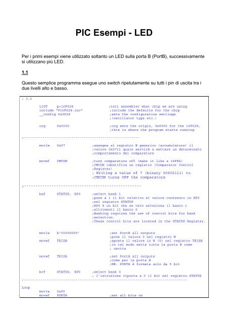
<strong>PIC</strong> <strong>Esempi</strong> - <strong>LED</strong><br />
Per i primi esempi viene utilizzato soltanto un <strong>LED</strong> sulla porta B (PortB), successivamente<br />
si utilizzano più <strong>LED</strong>.<br />
1.1<br />
Questo semplice programma esegue uno switch ripetutamente su tutti i pin <strong>di</strong> uscita tra i<br />
due livelli alto e basso.<br />
; 1.1<br />
LIST p=16F628 ;tell assembler what chip we are using<br />
include "P16F628.inc" ;include the defaults for the chip<br />
__config 0x3D18 ;sets the configuration settings<br />
;(oscillator type etc.)<br />
org 0x0000 ;org sets the origin, 0x0000 for the 16F628,<br />
;this is where the program starts running<br />
;--------------------------------------------------------<br />
movlw 0x07 ;assegna al registro W generico (accumulatore) il<br />
;valore 0x07il quale servirà a settare un determinato<br />
;comportamento del comparatore<br />
movwf CMCON ;turn comparators off (make it like a 16F84)<br />
;CMCON identifica un registro (Comparator Control<br />
;Register)<br />
; Writing a value of 7 (binary 00000111) to<br />
;CMCON turns OFF the comparators<br />
;---------------------------------------------------<br />
bsf STATUS, RP0 ;select bank 1<br />
;pone a 1 il bit relativo al valore contenuto in RP0<br />
;nel registro STATUS<br />
;RP0 è un bit che se vero seleziona il banco 1<br />
;altrimenti il banco 0<br />
;Banking requires the use of control bits for bank<br />
;selection.<br />
;These control bits are located in the STATUS Register.<br />
movlw b'00000000' ;set PortB all outputs<br />
;pone il valore 0 nel registro W<br />
movwf TRISB ;sposta il valore in W (0) nel registro TRISB<br />
;in tal modo setta tutta la porta B come<br />
; uscita<br />
movwf TRISA ;set PortA all outputs<br />
;come per la porta B<br />
;NB. PORTA è formata solo da 5 bit<br />
bcf STATUS, RP0 ;select bank 0<br />
; l’istruzione riporta a 0 il bit nel registro STATUS<br />
;-------------------------------------------------------------------------------<br />
Loop<br />
movlw 0xff<br />
movwf PORTA ;set all bits on
movwf PORTB<br />
nop ;the nop's make up the time taken by the goto<br />
nop ;giving a square wave output<br />
movlw 0x00<br />
movwf PORTA<br />
movwf PORTB ;set all bits off<br />
goto Loop ;go back and do it again<br />
end<br />
Le prime tre righe sono istruzioni per l’assemblatore, non sono parte integrante del<br />
programma, lasciamole come sono in questi esempi senza farci troppe domande sul<br />
perchè ci sono. La __Config setta le varie configurazioni possibili del chip, in questo caso<br />
viene selezionato l’oscillatore interno a 4MHz. La riga successiva “org 0x0000” setta<br />
l’in<strong>di</strong>rizzo iniziale, questo può variare a seconda del <strong>PIC</strong> usato ma i più moderni utilizzano<br />
l’in<strong>di</strong>rizzo più basso (zero).<br />
Le righe 5 e 6:<br />
“movlw 0x07” significa “MOVe the Literal value 7 into the W register”, il registro W è il<br />
registro <strong>di</strong> lavoro principale,<br />
“movwf CMCON” significa “MOV the value in W to File CMCON”, CMCON è un registro<br />
utilizzato per selezionare l’uso del comparatore hardware. Pertanto le due righe settano<br />
CMCON al valore 7, questo <strong>di</strong>sabilita il comparatore, e rende le relative linee <strong>di</strong> I/O<br />
<strong>di</strong>sponibili per uso generale.<br />
Le cinque righe successive settano la <strong>di</strong>rezione delle linee <strong>di</strong> I/O, inizialmente dobbiamo<br />
selezionare il “bank 1”, alcuni registri sono in “bank 0” ed altri in “bank 1”, per selezionare<br />
“bank 1” abbiamo bisogno <strong>di</strong> settare il bit RP0 nello STATUS register a “1” – il comando<br />
“bsf” (Bit Set File) setta un bit a uno. Il “bcf” (Bit Clear File) alla fine delle cinque righe,<br />
setta RP0 <strong>di</strong> nuovo a “0” e ritorna al “bank 0”.<br />
Il “movlw”, come prima, muove un valore nel registro W, questa volta però il valore<br />
passato è un valore binario (anzichè esadecimale 0x00), questo è in<strong>di</strong>cato dalla “b” prima<br />
del valore stesso, in questo caso è semplicemente zero, e questo valore è poi trasferito ai<br />
due registri TRIS (TRIState) A e B. Questo setta la <strong>di</strong>rezione dei pin, un valore “0” setta<br />
un pin come Uscita, mentre un “1” lo setta come Ingresso – pertanto il valore b'00000000'<br />
(otto zero) setta tutti i pin come Uscita, b'10000000' setterà il pin 7 come un ingresso, e<br />
tutti gli altri come uscite – utilizzando un balore binario risulta semplice vedere quale quali<br />
pin soni ingressi (1) e quali uscite (0).<br />
Questo completa il set up del chip, adesso <strong>di</strong>scutiamo la vera parte del programma che<br />
produrrà delle azioni, si inizia con l’etichetta “Loop”, l’ultimo comando “goto Loop' fa si che<br />
il programma ritorni al punto relativo all’etichetta, e esegue un loop infinito.<br />
La prima istruzione <strong>di</strong> questa sezione è “movlw 0xff” questa muove il numero esadecimale<br />
0xff (255 decimale, 11111111 binario) nel registro W, la seconda e la terza in seguito<br />
trasferiscono questo valore alla PortA e alla PortB <strong>di</strong> I/O – questo “prova” a settare tutti i<br />
16 pin (approfon<strong>di</strong>remo in seguito!).
Le due istruzioni seguenti sono “nop” “NO Operation”, questa istruzione richiede 1uS per<br />
essere eseguita e non fa niente, vengono utilizzate solo per mantenere le uscite alte per<br />
un extra time <strong>di</strong> 2uS.<br />
Poi abbiamo “movlw 0x00” la quale muove 0x00 (0 decimale, 00000000 binario) nel<br />
registro W, poi verrà trasferito alle porte come visto prima, questo setta tutti e 16 le uscite<br />
al livello basso. L’ultimo “goto Loop” ritorna all’inizio e permette <strong>di</strong> rieseguire la sezione<br />
all’infinito, continuerà switchando le porte al valore alto e basso.<br />
1.2<br />
Come avete potuto notare nella prima parte (implementando il co<strong>di</strong>ce <strong>di</strong> cui sopra), i <strong>LED</strong>'s<br />
non lampeggiano!. In realtà i <strong>LED</strong> lampeggiano ma lo fanno troppo velocemente<br />
affinchè sia visibile. Il <strong>PIC</strong> esegue ciascuna istruzione a 4MHz, pertanto impiega 1uS per<br />
completare (ad eccezione del “jump”, che impiega 2uS), questo fa si che i <strong>LED</strong><br />
lampeggino migliaia <strong>di</strong> volte al secondo – troppo veloce per i nostri occhi!. Questo è un<br />
problema comune nella programmazione <strong>di</strong> microcontrollori che interagiscono con<br />
ambienti fisici esterni, girano troppo velocemente rispetto al mondo esterno, spesso<br />
abbiamo bisogno <strong>di</strong> rallentare l’esecuzione!.<br />
Anche questo secondo esempio cambia lo stato delle porte <strong>di</strong> uscita da alto a basso e<br />
viceversa, ma questa volta utilizziamo un delay fra i due cambi <strong>di</strong> stato.<br />
; 1.2<br />
LIST p=16F628 ;tell assembler what chip we are using<br />
include "P16F628.inc" ;include the defaults for the chip<br />
__config 0x3D18 ;sets the configuration settings (oscillator type etc.)<br />
cblock 0x20 ;<strong>di</strong>rettiva del compilatore<br />
;start of general purpose registers<br />
count1 ;used in delay routine<br />
counta ;used in delay routine<br />
countb ;used in delay routine<br />
endc ;fine <strong>di</strong>rettiva<br />
org 0x0000 ;org sets the origin, 0x0000 for the 16F628,<br />
;this is where the program starts running<br />
movlw 0x07<br />
movwf CMCON ;turn comparators off (make it like a 16F84)<br />
bsf STATUS, RP0 ;select bank 1<br />
movlw b'00000000'<br />
movwf TRISB ;set PortB all outputs<br />
movwf TRISA ;set PortA all outputs<br />
bcf STATUS, RP0 ;select bank 0<br />
Loop<br />
movlw 0xff<br />
movwf PORTA ;set all bits on<br />
movwf PORTB<br />
nop ;the nop's make up the time taken by the goto<br />
nop ;giving a square wave output<br />
;---------------------------------------------------------------------------------call<br />
Delay ;this waits for a while!<br />
;viene richiamata la routine <strong>di</strong> nome Delay<br />
movlw 0x00<br />
movwf PORTA<br />
movwf PORTB ;set all bits off<br />
call Delay ;ritardo
goto Loop ;go back and do it again<br />
;acceso wait spento wait acceso wait spento wait ...................<br />
;---------------------------------------------------------------------------------<br />
; <strong>di</strong> seguito abbiamo la routine in grado <strong>di</strong> contare 250ms<br />
Delay movlw d'250' ;delay 250 ms (4 MHz clock)<br />
;nel registro W si inserisce il valore 250<br />
movwf count1 ; tale valore (250) viene passato al registro<br />
;countl<br />
d1 movlw 0xC7 ;199 volte<br />
movwf counta ;assegna 199 al registro conta<br />
movlw 0x05 ;5 volte<br />
movwf countb assegna 5 al registo contb<br />
Delay_0<br />
decfsz counta, f ;decrementa il registro conta e se zero passa<br />
;alla riga successiva<br />
goto $+2 ;passa 2 istruzioni in avanti (ne salta una)<br />
decfsz countb, f<br />
goto Delay_0<br />
decfsz count1 ,f<br />
goto d1<br />
retlw 0x00 ;ritorno dalla chiamata <strong>di</strong> subroutine<br />
;inoltre in grado <strong>di</strong> restituire un valore<br />
;nel registro accumulatore (non interessa)<br />
end<br />
Questo non fa altro che introdurre due righe <strong>di</strong> co<strong>di</strong>ce in più nel main, “call Delay”, questa<br />
è una chiamata ad una subroutine, una parte del programma che esegue e poi ritorna<br />
dove è stata chiamata. La routine è richiamata due volte, una dopo che i <strong>LED</strong> sono<br />
<strong>di</strong>ventati accesi, e nuovamente dopo il loro spegnimento. Tutta la routine “Delay” è tempo<br />
perso, cicla continuamente fino a quando non termina.<br />
La parte aggiunta all’inizio del programma (cblock to endc) alloca una coppia <strong>di</strong> variabili<br />
(count1 and count2) a due dei registri “general purpose file registers”, questi iniziano alla<br />
locazione 0x20 – la <strong>di</strong>rettiva cblock alloca la prima variabile a 0x20, e seguenti.<br />
The cblock <strong>di</strong>rective allows you to define several bytes together. For example:<br />
cblock 0x70<br />
temp<br />
x, y<br />
endc<br />
This bit of assembler defines 3 bytes that will be at locations 0x70 (temp), 0x71 (x), and<br />
0x72 (y). Note that if you put multiple items on the same line, you need a comma between<br />
them.<br />
La routine “Delay” realizza un ritardo <strong>di</strong> 250mS, settato nella sua prima riga (movlw d'250')<br />
– la “d” in<strong>di</strong>ca che si tratta <strong>di</strong> un numero decimale, per facilitarne la comprensione –<br />
pertanto si accenono i <strong>LED</strong>, si aspettano 250mS, si spengono i <strong>LED</strong>, si attendono altri<br />
250mS, e poi si ripete. Questo fa si che i <strong>LED</strong> lampeggino 2 volte al secondo, adesso sarà
certamente visibile il lampeggiamento. Alterando il valore d'250' si può mo<strong>di</strong>ficare il flash<br />
rate, comunque poichè al massimo <strong>di</strong>sponiamo <strong>di</strong> 8 bit il valore non potrà essere più <strong>di</strong><br />
d'255' (0xff esadecimale).<br />
Figura 1 – Registri speciali<br />
Figura 2 – Registri Generici<br />
Questa routine introduce un nuovo comando “decfsz” “Decrement File and Skip on Zero”,<br />
questo decrementa il file register specificato (in questo caso count2, o count1) e se il<br />
risultato è uguale a zero passa oltre la riga successiva. Pertanto questa prima sezione<br />
utilizzando il seguente,<br />
d2 decfsz count2 ,f<br />
goto d2<br />
decrementa count2, controlla se è uguale a zero, e altrimenti continua verso il “goto d2”, il<br />
quale risalta in<strong>di</strong>etro e decrementa count2 nuovamente, continua fino a quando count2 è<br />
uguale a zero, poi “goto d2” viene ignorato e count1 viene decrementato nello stesso<br />
modo, questa volta tornando all’inizio del loop count2, e così via. Questo è detto “nested<br />
loop”, il ciclo interno impiega 1mS per eseguire, e quello esterno chiama quello interno un<br />
numero <strong>di</strong> volte specificato in count1 –<br />
così se carichiamo 0x01 in count1 la routine Delay impiegherà 1mS, nell’esempio utilizzato<br />
noi carichiamo d'250' (hex 0xfa) in count1, così impiegherà 250mS (1/4 <strong>di</strong> secondo).<br />
L’altro comando nuovo è “retlw” “RETurn from subroutine with Literal in W”, ritorna dove è<br />
stata chiamata la subroutine, e restituisce un valore opzionale nel registro W (non è però<br />
utilizzato per restituire tale valore in questo esempio, pertanto gli assegnamo 0x00).
Dicevamo che le routine al max possono dare un ritardo massimo <strong>di</strong> 255mS, se volessimo<br />
un tempo maggiore dovremmo introdurre un altro ciclo esterno che richiama la routine<br />
“Delay” in numero <strong>di</strong> volte che ci serve, se vogliamo far lampeggiare i <strong>LED</strong> una volta al<br />
secondo (anziché due) possiamo semplicemente duplicare la riga “call Delay”,<br />
nop ;giving a square wave output<br />
call Delay ;this waits for a while!<br />
call Delay ;second delay call added<br />
movlw 0x00<br />
questo dà un ritardo <strong>di</strong> 500mS, mantenendo il <strong>LED</strong> acceso per 1/2 secondo, aggiungendo<br />
una seconda chiamata “call Delay” al “off time” il <strong>LED</strong> starà spento per 1/2 secon<strong>di</strong>. Non<br />
c’è inoltre bisogno <strong>di</strong> questa simmetria, usando una chiamata “call Delay” per il “on time”,<br />
e tre per il “off time” il <strong>LED</strong> continuerà a lampeggiare una volta al secondo ma sarà acceso<br />
per 1/4 del tempo (25/75) – utilizzerà solo il 50% dell’energia rispetto a un 50/50.<br />
Ci sono interessanti vantaggi nell’usare subroutine, una routine come quella del ritar<strong>di</strong><br />
può essere usata in molte parti del co<strong>di</strong>ce ripetutamente, quin<strong>di</strong> salvandola una volta<br />
si risparmia spazio. Inoltre mo<strong>di</strong>fiche non richiederanno <strong>di</strong> mo<strong>di</strong>ficare in più parti il co<strong>di</strong>ce<br />
ma solo la subroutine, il cambiamento si ripercuoterà a tutte le chiamate alla subroutine.<br />
1.3<br />
I due esempi precedenti accendevano semplicemente i <strong>LED</strong> ponendo i pin alti o bassi,<br />
spesso vogliamo agire su un solo pin, questo è facilmente realizzabile con il comando<br />
“bcf” e “bsf”, “bcf” “Bit Clear File” pone un bit a zero, e “bsf” “Bit Set File” pone un bit a 1, il<br />
range dei bit va da 0 (LSB) a 7 (MSB). Il seguente esempio fa lampeggiare il bit 7 (RB7)<br />
della PortB, mentre gli altri bit resteranno a zero.<br />
; 1.3<br />
LIST p=16F628<br />
;tell assembler what chip we are using<br />
include "P16F628.inc" ;include the defaults for the chip<br />
__config 0x3D18 ;sets the configuration settings (oscillator<br />
type etc.)<br />
Loop<br />
cblock 0x20 ;start of general purpose registers<br />
count1 ;used in delay routine<br />
counta ;used in delay routine<br />
countb ;used in delay routine<br />
endc<br />
org 0x0000 ;org sets the origin, 0x0000 for the 16F628,<br />
;this is where the program starts running<br />
movlw 0x07<br />
movwf CMCON ;turn comparators off (make it like a 16F84)<br />
bsf STATUS, RP0 ;select bank 1<br />
movlw b'00000000' ;set PortB all outputs<br />
movwf TRISB<br />
movwf TRISA ;set PortA all outputs<br />
bcf STATUS, RP0 ;select bank 0<br />
clrf PORTA<br />
clrf PORTB ;set all outputs low<br />
bsf PORTB, 7 ;turn on RB7 only!<br />
call Delay ;this waits for a while!
cf PORTB, 7 ;turn off RB7 only!.<br />
call Delay<br />
goto Loop ;go back and do it again<br />
Delay movlw d'3' ;delay 250 ms (4 MHz clock) 250=FA<br />
movwf count1<br />
d1 movlw 0x17 ;delay 1mS C7=199<br />
movwf counta<br />
movlw 0x01<br />
movwf countb<br />
Delay_0<br />
decfsz counta, f<br />
goto $+2<br />
decfsz countb, f<br />
goto Delay_0<br />
decfsz count1 ,f<br />
goto d1<br />
retlw 0x00<br />
end<br />
Il “movwf PORTA” e il “movwf PORTB” sono state rimpiazzate da una singola riga<br />
“bsf PORTB, 7” (per accendere il <strong>LED</strong>), e “bcf PORTB, 7” (per spegnere il <strong>LED</strong>). Le<br />
righe associate “movlw 0xff” e “movlw 0x00” sono state eliminate, poichè non servono più,<br />
i due “nop” sono stati rimossi, sono superflui – non ci interessa aggiungere 2uS ad una<br />
routine che dura 250mS.<br />
1.4<br />
Se vogliamo utilizzare un pin <strong>di</strong>verso rispetto all’RB7, basterà cambiare il “7” nelle due<br />
righe prima viste. Questo esempio (funzionalmente identico al precedente) assegna due<br />
costanti all’inizio del programma, <strong>LED</strong>, e <strong>LED</strong>PORT – a questi vengono assegnati i valori<br />
“7” e “PORTB”, e questi nomi <strong>di</strong> costanti sono utilizzati in “bsf” e “bcf”. L’uso delle costanti<br />
facilita così eventuali cambiamenti alle assegnazioni dei pin.<br />
; 1.4<br />
LIST p=16F628 ;tell assembler what chip we are using<br />
include "P16F628.inc" ;include the defaults for the chip<br />
__config 0x3D18<br />
type etc.)<br />
;sets the configuration settings (oscillator<br />
cblock 0x20 ;start of general purpose registers<br />
count1 ;used in delay routine<br />
counta ;used in delay routine<br />
countb ;used in delay routine<br />
endc<br />
<strong>LED</strong> Equ 7 ;set constant <strong>LED</strong> = 7 <strong>di</strong>chiara una costante<br />
<strong>LED</strong>PORT Equ PORTB ;set constant <strong>LED</strong>PORT = 'PORTB'<br />
org 0x0000 ;org sets the origin, 0x0000 for the 16F628,<br />
;this is where the program starts running<br />
movlw 0x07<br />
movwf CMCON ;turn comparators off (make it like a 16F84)<br />
bsf STATUS, RP0 ;select bank 1<br />
movlw b'00000000' ;set PortB all outputs<br />
movwf TRISB<br />
movwf TRISA ;set PortA all outputs<br />
bcf STATUS, RP0 ;select bank 0<br />
clrf PORTA
Loop<br />
clrf PORTB ;set all outputs low<br />
bsf <strong>LED</strong>PORT, <strong>LED</strong> ;turn on RB7 only!<br />
call Delay ;this waits for a while!<br />
bcf <strong>LED</strong>PORT, <strong>LED</strong> ;turn off RB7 only!.<br />
call Delay<br />
goto Loop ;go back and do it again<br />
Delay movlw d'250' ;delay 250 ms (4 MHz clock)<br />
movwf count1<br />
d1 movlw 0xC7 ;delay 1mS<br />
movwf counta<br />
movlw 0x01<br />
movwf countb<br />
Delay_0<br />
decfsz counta, f<br />
goto $+2<br />
decfsz countb, f<br />
goto Delay_0<br />
decfsz count1 ,f<br />
goto d1<br />
retlw 0x00<br />
end<br />
Questo lavora esattamente come la versione precedente infatti comparando i relativi file<br />
HEX questi risulteranno identici.<br />
Esercizi<br />
• Alterare il numero delle chiamate della Delay in modo tale da produrre<br />
lampeggiamenti asimmetrici.<br />
• Cambiare l’assegnamento dei pin.<br />
• Far lampeggiare più <strong>di</strong> un <strong>LED</strong> ma meno <strong>di</strong> 8 contemporaneamente - TIP:<br />
aggiungere extra coman<strong>di</strong> del tipo “bsf” e “bcf”. Aggiungere altri <strong>LED</strong> lampeggianti<br />
utilizzando <strong>di</strong>versi rate -TIP: far lampeggiare uno on/off, poi un altro on/off,<br />
aggiungendo <strong>di</strong>verse chiamate a Delay.<br />
Gli esempi successivi usano più <strong>LED</strong> (<strong>LED</strong> board)
1.5<br />
Usando la <strong>LED</strong> board si fa girare un <strong>LED</strong> all’interno della riga.<br />
; 1.5<br />
LIST p=16F628 ;tell assembler what chip we are using<br />
include "P16F628.inc" ;include the defaults for the chip<br />
__config 0x3D18 ;sets the configuration settings (oscillator<br />
; type etc.)<br />
cblock 0x20 ;start of general purpose registers<br />
count1 ;used in delay routine<br />
counta ;used in delay routine<br />
countb ;used in delay routine<br />
endc<br />
<strong>LED</strong>PORT Equ PORTB ;set constant <strong>LED</strong>PORT = 'PORTB'<br />
<strong>LED</strong>TRIS Equ TRISB ;set constant for TRIS register<br />
org 0x0000 ;org sets the origin, 0x0000 for the 16F628,<br />
:------------------- this is where the program starts running<br />
Loop<br />
movlw 0x07 ;il valore 7 al registro del comparatore<br />
;esclude il comparatore hw<br />
movwf CMCON ;turn comparators off (make it like a 16F84)<br />
bsf STATUS, RP0 ;select bank 1<br />
movlw b'00000000' ;set PortB all outputs<br />
movwf <strong>LED</strong>TRIS<br />
bcf STATUS, RP0 ;select bank 0<br />
clrf <strong>LED</strong>PORT ;set all outputs low<br />
movlw b'10000000'<br />
movwf <strong>LED</strong>PORT<br />
call Delay ;this waits for a while!<br />
movlw b'01000000'<br />
movwf <strong>LED</strong>PORT<br />
call Delay ;this waits for a while!<br />
movlw b'00100000'<br />
movwf <strong>LED</strong>PORT<br />
call Delay ;this waits for a while!<br />
movlw b'00010000'<br />
movwf <strong>LED</strong>PORT<br />
call Delay ;this waits for a while!<br />
movlw b'00001000'<br />
movwf <strong>LED</strong>PORT<br />
call Delay ;this waits for a while!<br />
movlw b'00000100'<br />
movwf <strong>LED</strong>PORT<br />
call Delay ;this waits for a while!<br />
movlw b'00000010'<br />
movwf <strong>LED</strong>PORT<br />
call Delay ;this waits for a while!<br />
movlw b'00000001'<br />
movwf <strong>LED</strong>PORT<br />
call Delay ;this waits for a while!<br />
goto Loop ;go back and do it again
Delay movlw d'250' ;delay 250 ms (4 MHz clock)<br />
movwf count1<br />
d1 movlw 0xC7<br />
movwf counta<br />
movlw 0x01<br />
movwf countb<br />
Delay_0<br />
decfsz counta, f<br />
goto $+2<br />
decfsz countb, f<br />
goto Delay_0<br />
1.6<br />
decfsz count1 ,f<br />
goto d1<br />
retlw 0x00<br />
end<br />
Possiamo facilmente mo<strong>di</strong>ficare la routine sopra in modo tale che il <strong>LED</strong> rimbalzi da una<br />
parte all’altre, semplicemente aggiungendo altre “movlw” e “movwf” più la riga “call<br />
Delay”.<br />
; 1.6<br />
LIST p=16F628 ;tell assembler what chip we are using<br />
include "P16F628.inc" ;include the defaults for the chip<br />
__config 0x3D18 ;sets the configuration settings (oscillator<br />
;type etc.)<br />
cblock 0x20 ;start of general purpose registers<br />
count1 ;used in delay routine<br />
counta ;used in delay routine<br />
countb ;used in delay routine<br />
endc<br />
<strong>LED</strong>PORT Equ PORTB ;set constant <strong>LED</strong>PORT = 'PORTB'<br />
<strong>LED</strong>TRIS Equ TRISB ;set constant for TRIS register<br />
org 0x0000 ;org sets the origin, 0x0000 for the 16F628,<br />
;--------------------------- ;this is where the program starts running<br />
Loop<br />
movlw 0x07<br />
movwf CMCON ;turn comparators off (make it like a 16F84)<br />
bsf STATUS, RP0 ;select bank 1<br />
movlw b'00000000' ;set PortB all outputs<br />
movwf <strong>LED</strong>TRIS<br />
bcf STATUS, RP0 ;select bank 0<br />
clrf <strong>LED</strong>PORT ;set all outputs low<br />
movlw b'10000000'<br />
movwf <strong>LED</strong>PORT<br />
call Delay ;this waits for a while!<br />
movlw b'01000000'<br />
movwf <strong>LED</strong>PORT<br />
call Delay ;this waits for a while!<br />
movlw b'00100000'<br />
movwf <strong>LED</strong>PORT<br />
call Delay ;this waits for a while!
movlw b'00010000'<br />
movwf <strong>LED</strong>PORT<br />
call Delay ;this waits for a while!<br />
movlw b'00001000'<br />
movwf <strong>LED</strong>PORT<br />
call Delay ;this waits for a while!<br />
movlw b'00000100'<br />
movwf <strong>LED</strong>PORT<br />
call Delay ;this waits for a while!<br />
movlw b'00000010'<br />
movwf <strong>LED</strong>PORT<br />
call Delay ;this waits for a while!<br />
movlw b'00000001'<br />
movwf <strong>LED</strong>PORT<br />
call Delay ;this waits for a while!<br />
movlw b'00000010'<br />
movwf <strong>LED</strong>PORT<br />
call Delay ;this waits for a while!<br />
movlw b'00000100'<br />
movwf <strong>LED</strong>PORT<br />
call Delay ;this waits for a while!<br />
movlw b'00001000'<br />
movwf <strong>LED</strong>PORT<br />
call Delay ;this waits for a while!<br />
movlw b'00010000'<br />
movwf <strong>LED</strong>PORT<br />
call Delay ;this waits for a while!<br />
movlw b'00100000'<br />
movwf <strong>LED</strong>PORT<br />
call Delay ;this waits for a while!<br />
movlw b'01000000'<br />
movwf <strong>LED</strong>PORT<br />
call Delay ;this waits for a while!<br />
goto Loop ;go back and do it again<br />
Delay movlw d'250' ;delay 250 ms (4 MHz clock)<br />
movwf count1<br />
d1 movlw 0xC7<br />
movwf counta<br />
movlw 0x01<br />
movwf countb<br />
Delay_0<br />
decfsz counta, f<br />
goto $+2<br />
decfsz countb, f<br />
goto Delay_0<br />
1.7<br />
decfsz count1 ,f<br />
goto d1<br />
retlw 0x00<br />
end
Nonostante le due precedenti routine siano funzionanti, sono però ru<strong>di</strong>mentali. .5 usa 24<br />
righe all’interno del loop, utilizzando un altro comando del <strong>PIC</strong> si può ridurre il numero <strong>di</strong><br />
righe <strong>di</strong> co<strong>di</strong>ce.<br />
; 1.7<br />
LIST p=16F628 ;tell assembler what chip we are using<br />
include "P16F628.inc" ;include the defaults for the chip<br />
__config 0x3D18<br />
type etc.)<br />
;sets the configuration settings (oscillator<br />
cblock 0x20 ;start of general purpose registers<br />
count1 ;used in delay routine<br />
counta ;used in delay routine<br />
countb ;used in delay routine<br />
endc<br />
<strong>LED</strong>PORT Equ PORTB ;set constant <strong>LED</strong>PORT = 'PORTB'<br />
<strong>LED</strong>TRIS Equ TRISB ;set constant for TRIS register<br />
org 0x0000 ;org sets the origin, 0x0000 for the 16F628,<br />
;------------------- this is where the program starts running<br />
movlw 0x07<br />
movwf CMCON ;turn comparators off (make it like a 16F84)<br />
bsf STATUS, RP0 ;select bank 1<br />
movlw b'00000000' ;set PortB all outputs<br />
movwf <strong>LED</strong>TRIS<br />
bcf STATUS, RP0 ;select bank 0<br />
clrf <strong>LED</strong>PORT ;set all outputs low<br />
Start movlw b'10000000' ;set first <strong>LED</strong> lit<br />
movwf <strong>LED</strong>PORT<br />
Loop bcf STATUS, C ;clear carry bit<br />
call Delay ;this waits for a while!<br />
rrf <strong>LED</strong>PORT, f ;ruota il contenuto del registro <strong>LED</strong>PORT<br />
;un bit a destra attraverso il riporto<br />
;il valore <strong>di</strong> f è 1 pertanto il<br />
;risultato viene rimesso nel registro<br />
;se fosse 0 il risultato andrebbe in W<br />
btfss STATUS, C ;check if last bit (1 rotated into Carry)<br />
;se il bit del riporto nel registro STATUS<br />
;è 0 allora esegue l’istruzione successiva,<br />
;altrimenti la salta e sostituisce con NOP<br />
goto Loop ;go back and do it again<br />
goto Start<br />
Delay movlw d'250' ;delay 250 ms (4 MHz clock)<br />
movwf count1<br />
d1 movlw 0xC7<br />
movwf counta<br />
movlw 0x01<br />
movwf countb<br />
Delay_0<br />
decfsz counta, f<br />
goto $+2<br />
decfsz countb, f<br />
goto Delay_0<br />
decfsz count1 ,f<br />
goto d1<br />
retlw 0x00<br />
end
Questo esempio introduce il comando 'rrf” “Rotate Right File”, ruota il contenuto del file<br />
register verso destra (<strong>di</strong>vide il valore per 2). Poichè il comando “rrf” ruota passando dal<br />
“carry” bit occorre essere sicuri questo sia svuotato con il comando “bcf STATUS, C”. Per<br />
verificare il raggiungimento della fine utilizziamo la riga “btfss STATUS, C” per verificare<br />
quando il CARRY bit è settato, questo restart la sequenza <strong>di</strong> bit dal 7.<br />
1.8<br />
Possiamo applicare questo metodo anche al 1.6, in questo caso aggiungendo il comando<br />
“rlf” “Rotate Left File”, questo shifta il contenuto del registro a sinistra (moltiplicando per 2).<br />
; 1.8<br />
LIST p=16F628 ;tell assembler what chip we are using<br />
include "P16F628.inc" ;include the defaults for the chip<br />
__config 0x3D18<br />
type etc.)<br />
;sets the configuration settings (oscillator<br />
cblock 0x20 ;start of general purpose registers<br />
count1 ;used in delay routine<br />
counta ;used in delay routine<br />
countb ;used in delay routine<br />
endc<br />
<strong>LED</strong>PORT Equ PORTB ;set constant <strong>LED</strong>PORT = 'PORTB'<br />
<strong>LED</strong>TRIS Equ TRISB ;set constant for TRIS register<br />
org 0x0000 ;org sets the origin, 0x0000 for the 16F628,<br />
;------------------ this is where the program starts running<br />
movlw 0x07<br />
movwf CMCON ;turn comparators off (make it like a 16F84)<br />
bsf STATUS, RP0 ;select bank 1<br />
movlw b'00000000' ;set PortB all outputs<br />
movwf <strong>LED</strong>TRIS<br />
bcf STATUS, RP0 ;select bank 0<br />
clrf <strong>LED</strong>PORT ;set all outputs low<br />
Start movlw b'10000000' ;set first <strong>LED</strong> lit<br />
movwf <strong>LED</strong>PORT<br />
;------------- sposta a destra<br />
Loop bcf STATUS, C ;clear carry bit<br />
call Delay ;this waits for a while!<br />
rrf <strong>LED</strong>PORT, f<br />
btfss STATUS, C ;check if last bit (1 rotated into Carry)<br />
goto Loop ;go back and do it again<br />
movlw b'00000001' ;set last <strong>LED</strong> lit<br />
movwf <strong>LED</strong>PORT<br />
;------------- sposta a sinistra<br />
Loop2 bcf STATUS, C ;clear carry bit<br />
call Delay ;this waits for a while!<br />
rlf <strong>LED</strong>PORT, f ;ruota verso sinistra<br />
btfss STATUS, C ;check if last bit (1 rotated into Carry)<br />
goto Loop2 ;go back and do it again<br />
goto Start ;finished, back to first loop<br />
Delay movlw d'250' ;delay 250 ms (4 MHz clock)<br />
movwf count1<br />
d1 movlw 0xC7<br />
movwf counta<br />
movlw 0x01
Delay_0<br />
1.9<br />
movwf countb<br />
decfsz counta, f<br />
goto $+2<br />
decfsz countb, f<br />
goto Delay_0<br />
decfsz count1 ,f<br />
goto d1<br />
retlw 0x00<br />
end<br />
Fino ad ora abbiamo utilizzato due meto<strong>di</strong> per creare il <strong>LED</strong> rimbalzante, adesso creiamo<br />
un’altra versione ancora, utilizzando un lookup table.<br />
; 1.9<br />
LIST p=16F628 ;tell assembler what chip we are using<br />
include "P16F628.inc" ;include the defaults for the chip<br />
__config 0x3D18<br />
type etc.)<br />
;sets the configuration settings (oscillator<br />
cblock 0x20 ;start of general purpose registers<br />
count ;used in table read routine<br />
count1 ;used in delay routine<br />
counta ;used in delay routine<br />
countb ;used in delay routine<br />
endc<br />
<strong>LED</strong>PORT Equ PORTB ;set constant <strong>LED</strong>PORT = 'PORTB'<br />
<strong>LED</strong>TRIS Equ TRISB ;set constant for TRIS register<br />
org 0x0000 ;org sets the origin, 0x0000 for the 16F628,<br />
;----------------------- this is where the program starts running<br />
movlw 0x07<br />
movwf CMCON ;turn comparators off (make it like a 16F84)<br />
bsf STATUS, RP0 ;select bank 1<br />
movlw b'00000000' ;set PortB all outputs<br />
movwf <strong>LED</strong>TRIS<br />
bcf STATUS, RP0 ;select bank 0<br />
clrf <strong>LED</strong>PORT ;set all outputs low<br />
Start clrf count ;set counter register “count” to zero<br />
Read movf count, w ;put counter value in W<br />
call Table ;chiama la sub “Table”<br />
movwf <strong>LED</strong>PORT ;sposta il contenuto <strong>di</strong> W alla porta B<br />
call Delay ;chiama la sub delay<br />
incf count, w ;incrementa <strong>di</strong> 1 il valore del registro count<br />
;e copia il valore in W<br />
xorlw d'14' ;check for last (14th) entry<br />
;verifica se W contiene il valore 14<br />
;se uguali setta il flag Z<br />
btfsc STATUS, Z ;se Z è settato an<strong>di</strong>amo alla riga successiva<br />
;altrimenti saltiamo una riga<br />
goto Start ;if start from beginning<br />
incf count, f ;else do next incrementa il valore count<br />
goto Read
Table ADDWF PCL, f ;data table for bit pattern<br />
;aggiunge al program counter il valore<br />
;contenuto in W<br />
;in base al contenuto <strong>di</strong> W si salta infatti sommando al PC il valore <strong>di</strong> W<br />
;il PC si sposta a PC+W<br />
retlw b'10000000' ;inserisce il valore in W<br />
retlw b'01000000'<br />
retlw b'00100000'<br />
retlw b'00010000'<br />
retlw b'00001000'<br />
retlw b'00000100'<br />
retlw b'00000010'<br />
retlw b'00000001'<br />
retlw b'00000010'<br />
retlw b'00000100'<br />
retlw b'00001000'<br />
retlw b'00010000'<br />
retlw b'00100000'<br />
retlw b'01000000'<br />
Delay movlw d'250' ;delay 250 ms (4 MHz clock)<br />
movwf count1<br />
d1 movlw 0xC7<br />
movwf counta<br />
movlw 0x01<br />
movwf countb<br />
Delay_0<br />
decfsz counta, f<br />
goto $+2<br />
decfsz countb, f<br />
goto Delay_0<br />
decfsz count1 ,f<br />
goto d1<br />
retlw 0x00<br />
end<br />
Introduce un altro nuovo comando, il 'addwf” “ADD W to File”, è un comando <strong>di</strong> somma,<br />
infatti essendo il <strong>PIC</strong> con architettura RISC ha solo 35 coman<strong>di</strong>, pertanto alcuni<br />
coman<strong>di</strong> apparentemente semplici come la lettura dei dati <strong>di</strong> una tabella non sono<br />
presenti.<br />
Nel 1.2 abbiamo usato il comando “retlw”, senza usarne il valore restituito, adesso per<br />
creare la data table facciamo uso del valore restituito.<br />
Alla etichetta “Start” prima poniamo a zero un contatore che sarà poi utilizzato, il “clrf<br />
Count”, questo verrà poi spostato nel registro W me<strong>di</strong>ante “movf Count, w”, e la subroutine<br />
Table verrà chiamata.<br />
La prima riga della subroutine è “addwf PCL, f”, la quale somma il contenuto <strong>di</strong> W (che è<br />
stato appena settato a zero) con il registro PCL, il PCL è il Program Counter, conta<br />
esattamente dove si trova l’esecuzione del programma, perciò aggiungendovi zero ci si<br />
sposta alla riga successiva “retlw b’10000000' che restituisce b'10000000' nel registro W,<br />
Questo è poi spostato ai <strong>LED</strong>.<br />
l conteggio viene poi incrementato e il programma cicla richiamando nuovamente la Table,<br />
questa volta W contiene il valore 1, poi sommato a PCL il quale fa un salto <strong>di</strong> una riga e
estituisce la seguente riga della Table – si continua per il resto della table. Non è però<br />
una buona cosa superare la lunghezza della tabella, causando un salto del PCL ad una<br />
riga dopo alla tabella, la quale in questo caso è la Delay. Per evitarlo si controlla il valore<br />
<strong>di</strong> count, usando “xorlw d14” “eXclusive Or Literal with W”, il quale implementa un<br />
“exclusive or” con il registro W (dove si trova il valore <strong>di</strong> count) e il valore 14, e setta il flag<br />
“Z” “Zero” se sono uguali, poi controlliamo il flag Z, e se è settato facciamo un salto<br />
in<strong>di</strong>etro all’inizio e resettiamo count a zero e così via.<br />
Il vantaggio <strong>di</strong> questo sistema è la possibilità <strong>di</strong> avere qualsiasi pattern nella tabella e la<br />
facilità <strong>di</strong> mo<strong>di</strong>fica della stessa.