CIPREA D 24 - 32 A - Joannes
CIPREA D 24 - 32 A - Joannes
CIPREA D 24 - 32 A - Joannes

Create successful ePaper yourself
Turn your PDF publications into a flip-book with our unique Google optimized e-Paper software.
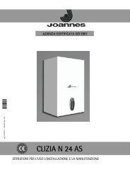
<strong>CIPREA</strong> D <strong>24</strong> - <strong>32</strong> A<br />
Room thermostat (optional)<br />
B<br />
IMPORTANT: THE ROOM THERMOSTAT MUST HAVE VOLTAGE-FREE<br />
CONTACTS. CONNECTING 230 V TO THE ROOM THERMOSTAT TERMI-<br />
NALS WILL PERMANENTLY DAMAGE THE ELECTRONIC BOARD.<br />
When connecting time controls or a timer, do not take the power supply for<br />
these devices from their breaking contacts Their power supply must be by<br />
means of direct connection from the mains or with batteries, depending on the<br />
kind of device.<br />
Accessing the electrical terminal block<br />
Follow the instructions given in fig. 8 to access the electrical connections terminal block. The<br />
layout of the terminals for the various connections is given in the wiring diagram in fig. 21.<br />
TEST mode activation<br />
Press the heating buttons (details 3fig. 1and 4 - ) together for 5 seconds to activate the<br />
TEST mode. The boiler lights at the maximum heating power set as described in the following<br />
section.<br />
The heating and DHW symbols (fig. 9) flash on the display; the heating power will be displayed<br />
alongside.<br />
bar<br />
138<br />
fig. 9 - TEST mode (heating power = 100%)<br />
72<br />
139<br />
fig. 8 - Accessing the terminal block<br />
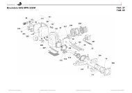
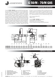
3.6 Air/fume ducts<br />
The diameter of the flue connection pipe must not be less than that of the connection on<br />
the anti-backflow device. Starting from the anti-backflow device it must have a vertical<br />
section at least 50 cm long. Current standards must be complied with regarding sizing<br />
and installation of the flues and connection pipe.<br />
B<br />
The boiler is also equipped with a safety device (fume thermostat) that stops<br />
operation of unit in case of inadequate draught of obstruction of the flue. This<br />
device must never be tampered with or deactivated.<br />
4. SERVICE AND MAINTENANCE<br />
4.1 Adjustments<br />
Gas conversion<br />
The unit can operate on natural gas or LPG and is factory-set for use with one of these<br />
two gases, as clearly shown on the packing and on the dataplate. Whenever a gas different<br />
from that for which the unit is arranged has to be used, the special conversion kit<br />
will be required, proceeding as follows:<br />
1. Replace the nozzles at the main burner, fitting the nozzles specified in the technical<br />
data table in cap. 5, according to the type of gas used<br />
2. Modify the parameter for the type of gas:<br />
• put the boiler in standby mode<br />
• press the DHW buttons details 1 and 2 - fig. 1 for 10 seconds: the display shows<br />
“b01“ blinking.<br />
• Press the DHW buttons fig. 1 (details 1 and 2 - ) to set parameter 00 (for natural<br />
gas operation) or 01 (for LPG operation).<br />
• press the DHW buttons details 1 and 2 - fig. 1 for 10 seconds.<br />
• the boiler will return to standby mode<br />
3. Adjust the minimum and maximum pressures at the burner (ref. relevant paragraph),<br />
setting the values given in the technical data table for the type of gas used<br />
4. Apply the sticker contained in the conversion kit, near the dataplate as proof of the<br />
conversion.<br />
Press the heating buttons (details 3 and 4 - fig. 1) to increase or decrease the power<br />
(min.=0%, max.=100%).<br />
Press the DHW button "-" (detail 1 - fig. 1) and the boiler power is immediately adjusted<br />
to min. (0%). Press the DHW button "+" (detail 2 - fig. 1) and the boiler power is immediately<br />
adjusted to max. (100%).<br />
To deactivate the TEST mode, press the heating buttons (details 3 and 4 - )<br />
togetherfig. 1for 5 seconds.<br />
The TEST mode is automatically disabled in any case after 15 minutes.<br />
Pressure adjustment at the burner<br />
Since this unit has flame modulation, there are two fixed pressure settings: minimum and<br />
maximum, which must be those given in the technical data table according to the type of gas.<br />
• Connect a suitable pressure gauge to the pressure point "B" downstream of the<br />
gas valve.<br />
• Activate the TEST mode (see cap. 4.1).<br />
• Press the Eco/Comfort button for 2 seconds to access the gas valve Calibration mode.<br />
• The card goes to the setting “q02”; displaying the actually saved value, by pressing<br />
the DHW buttons .<br />
• If the pressure gauge reading is different from the nominal maximum pressure, proceed<br />
by increases/decreases of 1 or 2 units of parameter “q02” by pressing the<br />
DHW buttons : the value is stored after each modification; wait 10 seconds for the<br />
pressure to stabilise.<br />
• Press the heating button “-” (ref. 3 - fig. 1).<br />
• The card goes to the setting “q01”; displaying the actually saved value, by pressing<br />
the DHW buttons .<br />
• If the pressure gauge reading is different from the nominal minimum pressure, proceed<br />
by increases/decreases of 1 or 2 units of parameter “q01” by pressing the<br />
DHW buttons : the value is stored after each modification; wait 10 seconds for the<br />
pressure to stabilise.<br />
• Recheck both adjustments by pressing the heating buttons and adjust them if necessary<br />
by repeating the above procedure.<br />
• Press the Eco/Comfort button for 2 seconds to return to the TEST mode.<br />
• Deactivate the TEST mode (see cap. 4.1).<br />
• Disconnect the pressure gauge.<br />
R<br />
B<br />
I<br />
A<br />
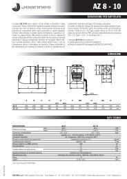
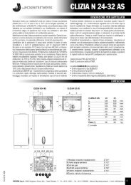
A - Upstream pressure point<br />
B - Downstream pressure point<br />
I - Gas valve electrical connection<br />
R - Gas outlet<br />
S - Gas inlet<br />
~ <strong>24</strong>Ω<br />
fig. 11 - Gas valve connection<br />
TYPE SGV100<br />
Pi max 65 mbar<br />
<strong>24</strong> Vdc - class B+A<br />
~ 65Ω<br />
S<br />
fig. 10 - Gas valve<br />
Heating power adjustment<br />
To adjust the heating power, switch the boiler to TEST mode (see sec. 4.1). Press the<br />
heating buttons detail 3 - fig. 1 to increase or decrease the power (min. = 00 - max. =<br />
100). Press the reset button within 5 seconds and the max. power will remain that just<br />
set. Exit TEST mode (see sec. 4.1).<br />
22 EN cod. 3541A341 - 05/2011 (Rev. 00)