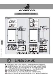
CIPREA D 24 - 32 A - Joannes
CIPREA D 24 - 32 A - Joannes
CIPREA D 24 - 32 A - Joannes

Create successful ePaper yourself
Turn your PDF publications into a flip-book with our unique Google optimized e-Paper software.
<strong>CIPREA</strong> D <strong>24</strong> - <strong>32</strong> A<br />
"In" - Information Menu<br />
6 pieces of information are available.<br />
Press the Heating buttons to scroll the list of information in increasing or decreasing order<br />
. Press the DHW buttons to display the value.<br />
Contents<br />
Description<br />
Range<br />
t01 NTC Heating sensor (°C) between 05 and 125°C<br />
t02 NTC Safety sensor (°C) between 05 and 125°C<br />
t03 NTC DHW sensor (°C) between 05 and 125°C<br />
t04 NTC External sensor (°C) between -30 and 70°C (negative values flash)<br />
L05 Actual burner power (%) 00%=Min., 100%=Max.<br />
F06 Actual Flame resistance(Ohm) 00-99 Ohm (-- = burner off)<br />
Notes:<br />
1. In case of damaged sensor, the card displays hyphens.<br />
Press the Reset button to return to the Service Menu. Press the Reset button for 20 seconds<br />
to exit the card Service Menu or exiting occurs automatically after 15 minutes.<br />
"Hi" - History Menu<br />
The card can store the last 11 faults: the History datum item H1: represents the most recent<br />
fault that occurred; the History datum item H10: represents the least recent fault that<br />
occurred.<br />
The codes of the faults saved are also displayed in the corresponding menu of the Remote<br />
Timer Control.<br />
Press the Heating buttons to scroll the list of faults in increasing or decreasing order.<br />
Press the DHW buttons to display the value.<br />
Press the Reset button to return to the Service Menu. Press the Reset button for 20 seconds<br />
to exit the card Service Menu, or exiting occurs automatically after 15 minutes.<br />
"rE" - History Reset<br />
Press the Eco/Comfort button for 3 seconds to delete all the faults stored in the History<br />
Menu: the card will automatically exit the Service Menu, in order to confirm the operation.<br />
Press the Reset button for 20 seconds to exit the card Service Menu, or exiting occurs<br />
automatically after 15 minutes.<br />
4.2 Startup<br />
Before lighting the boiler<br />
• Check the seal of the gas system.<br />
• Check correct prefilling of the expansion tank.<br />
• Fill the water system and make sure all air contained in the boiler and the system<br />
has been vented.<br />
• Make sure there are no water leaks in the system, DHW circuits, connections or boiler.<br />
• Check correct connection of the electrical system and efficiency of the earthing system.<br />
• Make sure the gas pressure for heating is that required.<br />
• Make sure there are no flammable liquids or materials in the immediate vicinity of<br />
the boiler<br />
Checks during operation<br />
• Switch the unit on.<br />
• Check the tightness of the fuel circuit and water systems.<br />
• Check the efficiency of the flue and air/fume ducts while the boiler is working.<br />
• Make sure the water is circulating properly between the boiler and the systems.<br />
• Make sure the gas valve modulates correctly in the heating and domestic hot water<br />
production stages.<br />
• Check correct boiler lighting by performing various tests, turning it on and off with<br />
the room thermostat or remote control.<br />
• Make sure the fuel consumption indicated on the meter matches that given in the<br />
technical data table in cap. 5.<br />
• Make sure that with no demand for heating, the burner lights correctly on opening a<br />
hot water tap. Check that in heating mode, on opening a hot water tap, the heating<br />
circulating pump stops and there is regular production of hot water.<br />
• Make sure the parameters are programmed correctly and carry out any required<br />
customisation (compensation curve, power, temperatures, etc.).<br />
4.3 Maintenance<br />
Periodical check<br />
To ensure correct operation of the unit over time, have qualified personnel carry out a<br />
yearly check, providing for the following:<br />
• The control and safety devices (gas valve, flow meter, thermostats, etc.) must function<br />
correctly.<br />
• The fume exhaust circuit must be perfectly efficient.<br />
(Sealed chamber boiler: fan, pressure switch, etc. -The sealed chamber must be<br />
tight: seals, cable glands, etc.)<br />
(Open chamber boiler: anti-backflow device, fume thermostat, etc.)<br />
• The air-fume end piece and ducts must be free of obstructions and leaks<br />
• The burner and exchanger must be clean and free of deposits. For possible cleaning<br />
do not use chemical products or wire brushes.<br />
• The electrode must be properly positioned and free of scale.<br />
fig. 12 - Electrode positioning<br />
• The gas and water systems must be airtight.<br />
• The water pressure in the cold water system must be about 1 bar; otherwise, bring<br />
it to that value.<br />
• The circulating pump must not be blocked.<br />
• The expansion tank must be filled.<br />
• The gas flow and pressure must correspond to that given in the respective tables.<br />
4.4 Troubleshooting<br />
Diagnostics<br />
The boiler is equipped with an advanced self-diagnosis system. In case of a boiler fault,<br />
the display will flash together with the fault symbol (detail 11 - fig. 1) indicating the fault<br />
code.<br />
There are faults that cause permanent shutdown (marked with the letter "A"): to restore<br />
operation, press the RESET button (detail 6 - fig. 1) for 1 second or RESET on the optional<br />
remote timer control if installed; if the boiler fails to start, it is necessary to eliminate<br />
the fault.<br />
Faults marked with the letter "F" cause temporary shutdowns that are automatically reset<br />
as soon as the value returns within the boiler's normal working range.<br />
List of faults<br />
Table. 2<br />
Fault<br />
code<br />
A01<br />
A02<br />
A03<br />
F04<br />
Fault Possible cause Cure<br />
No burner ignition<br />
Flame present signal with<br />
burner off<br />
Overtemperature protection<br />
activation<br />
Fume thermostat activated<br />
(after activation of the fume<br />
thermostat, boiler operation is<br />
prevented for 20 minutes)<br />
Check the regular gas flow to the boiler<br />
No gas<br />
and that the air has been eliminated<br />
from the pipes<br />
Check the wiring of the electrode and<br />
Ignition/detection electrode fault that it is correctly positioned and free<br />
of any deposits<br />
Faulty gas valve<br />
Check the gas valve and replace it if<br />
necessary<br />
Gas valve wiring disconnected Check the wiring<br />
Ignition power too low<br />
Adjust the ignition power<br />
Electrode fault<br />
Check the ionisation electrode wiring<br />
Card fault<br />
Check the card<br />
Heating sensor damaged<br />
Check the correct positioning and<br />
operation of the heating sensor<br />
No water circulation in the system Check the circulating pump<br />
Air in the system<br />
Vent the system<br />
Fume thermostat contact open Check the thermostat<br />
Wiring disconnected<br />
Check the wiring<br />
Flue obstructed or not correctly<br />
sized<br />
F05 Card parameter fault Wrong card parameter setting<br />
A06<br />
No flame after the ignition<br />
phase<br />
F07 Card parameter fault Wrong card parameter setting<br />
A09<br />
F10<br />
Gas valve fault<br />
Delivery sensor 1 fault<br />
= =<br />
3 ± 0,5<br />
Check the flue<br />
Check the card parameter and modify<br />
it if necessary<br />
Low pressure in the gas system Check the gas pressure<br />
Burner minimum pressure setting Check the pressures<br />
Check the card parameter and modify<br />
it if necessary<br />
Wiring disconnected<br />
Check the wiring<br />
Check the gas valve and replace it if<br />
Faulty gas valve<br />
necessary<br />
Sensor damaged<br />
Wiring shorted<br />
Check the wiring or replace the sensor<br />
Wiring disconnected<br />
<strong>24</strong> EN cod. 3541A341 - 05/2011 (Rev. 00)