Valvole Doppia Sede ZAW ZAW Double Seat Valves - Alflow
Valvole Doppia Sede ZAW ZAW Double Seat Valves - Alflow
Valvole Doppia Sede ZAW ZAW Double Seat Valves - Alflow

You also want an ePaper? Increase the reach of your titles
YUMPU automatically turns print PDFs into web optimized ePapers that Google loves.
<strong>Valvole</strong> <strong>Doppia</strong> <strong>Sede</strong> <strong>ZAW</strong><br />
<strong>ZAW</strong> <strong>Double</strong> <strong>Seat</strong> <strong>Valves</strong>
<strong>ZAW</strong><br />
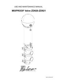
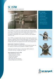
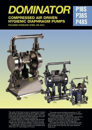
Valvola <strong>ZAW</strong><br />
<strong>Doppia</strong> sede<br />
La <strong>ZAW</strong> di Bardiani <strong>Valvole</strong> è una valvola pneumatica<br />
sanitaria a doppia sede, progettata<br />
per garantire la massima igiene e la massima<br />
sicurezza. Il cuore della valvola è rappresentato<br />
dall’otturatore a doppia sede e dalla<br />
presenza di due valvole esterne ausiliarie. La<br />
funzione delle valvole esterne è quella di assicurare<br />
il perfetto funzionamento e la perfetta<br />
pulizia della valvola. Se infatti si verificasse<br />
una perdita nella tenuta dell’otturatore le<br />
valvole poste in corrispondenza della camera<br />
evidenzierebbero una perdita esterna di<br />
prodotto. Inoltre è possibile utilizzare le due<br />
valvole come un circuito esterno di lavaggio,<br />
mantenendo costantemente pulita la camera<br />
tra le due sedi.<br />
<strong>ZAW</strong> valve<br />
<strong>Double</strong> seat<br />
The Bardiani <strong>ZAW</strong> is a sanitary double seat<br />
valve, designed to provide maximum hygiene<br />
and maximum safety. The valve core is<br />
represented by the double seat shutter and<br />
the two auxiliary valves. These auxiliary<br />
valves guarantee the perfect working and<br />
the maximum cleaning of the <strong>ZAW</strong> valve.<br />
In fact, if a leakage occurs on the shutter,<br />
the auxiliary valve, fitted between the two<br />
seats, show the product leakage. Moreover,<br />
the two auxiliary valves can be used as an<br />
auxiliary external cleaning, providing the<br />
cleaning of the double seat.<br />
2
Dati Tecnici<br />
Technical details<br />
Struttura valvola<br />
I corpi sono ricavati interamente da massello pieno, questo per evitare indebolimenti<br />
nelle zone di saldatura e per meglio sopportare carichi gravosi.<br />
- attacchi da DN25 a DN100: DIN, SMS, IDF, BS(RJT), ISO, Clamp, Flangia (attacchi<br />
diversi a richiesta)<br />
- pressione massima prodotto: 10 bar (145 psi)<br />
- pressione massima di tenuta vedi tabella<br />
- pressione minima prodotto: vuoto<br />
- temperatura massima prodotto: 140°C (284°F)<br />
- temperatura minima prodotto: -10°C (14°F)<br />
- materiale a contatto col prodotto: AISI 316L (1.4404)<br />
- materiale guarnizioni a contatto col prodotto (omologazione FDA): EPDM,<br />
FKM, MVQ(Silicone), NBR (altre guarnizioni a richiesta)<br />
- finitura superficiale a contatto col prodotto: Ra0.8μm (altri tipi di finitura<br />
a richiesta).<br />
Si consiglia l’applicazione in verticale.<br />
Struttura attuatore pneumatico<br />
- attacchi aria 1/8” (BSP)<br />
- pressione aria da 6bar (87psi) a 8bar (116psi)<br />
- materiale AISI 304L (1.4307)<br />
- materiale guarnizioni NBR<br />
Valve structure<br />
Valve bodies are made from solid stainless steel bar. This provides valve<br />
bodies with maximum strength avoiding any flows and stresses that may occur<br />
from welding processes.<br />
-connections from DN25 to DN100: DIN, SMS, IDF, BS(RJT), ISO, Clamp, Flange<br />
(different connections upon request)<br />
-max. working pressure: 10 bar (145 psi)<br />
-max. seal pressure: see table<br />
-min. working pressure: full vacuum<br />
-max. product temperature: 140°C (284°F)<br />
-min. product temperature: -10°C (14°F)<br />
-material in contact with the product: AISI 316L (1.4404)<br />
-gaskets in contact with the product: (homologation FDA): EPDM, FKM, MVQ<br />
(Silicon), NBR (other seals available upon request)<br />
-finish on surfaces in contact with the product: Ra0.8μm (other types of surface<br />
finish upon request).<br />
Vertical fitting is advisable<br />
Pneumatic actuator specifications<br />
-Air connectors 1/8” (BSP)<br />
-air pressure from 6 bar (87 psi) to 8 bar (116 psi)<br />
-material AISI 304L (1.4307)<br />
-gasket material NBR<br />
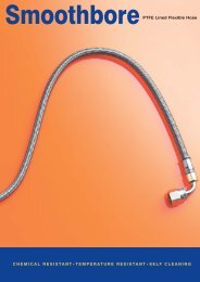
Interspazio ridotto<br />
Minimum recess<br />
3
<strong>ZAW</strong><br />
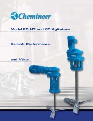
Soluzioni varie<br />
Different solutions<br />
Attacchi valvole ausiliarie / Auxiliary valves connections<br />
Saldare DN 6 Maschio BSP 1/4” Clamp 1/2”<br />
Welding DN 6 BSP 1/4” external Clamp 1/2”<br />
threading<br />
Possibilità orientamento a 360° gradi<br />
Possibility of 360° directions<br />
Posizionamento valvole ausiliari su richiesta<br />
Positioning of auxiliary valves on request<br />
4
Soluzioni varie<br />
Different solutions<br />
Barriera vapore<br />
Impiegata in applicazioni particolarmente delicate<br />
dove sterilità, asetticità o alte temperature di sterilizzazione<br />
sono necessarie. L’utilizzo di una barriera<br />
di vapore posta tra il corpo valvola e la parte pneumatica<br />
consente di ottenere una sicura separazione<br />
fra prodotto all’interno della valvola ed ambiente<br />
esterno. La Barriera Vapore di Bardiani valvole può<br />
essere impiegata in molteplici applicazioni, anche<br />
quando nell’impianto si vengono a creare delle depressioni.<br />
Steam barrier<br />
A steam barrier is recommended for very hygiene<br />
duties such as sterile, aseptic processing or high<br />
temperature sterilization. The steam barrier, placed<br />
between the valve body and the pneumatic actuator,<br />
minimises the risk of the product coming into contact<br />
with the external atmosphere.<br />
Soffietto metallico<br />
Il soffietto metallico in acciaio inossidabile garantisce la perfetta<br />
separazione tra prodotto ed ambiente esterno. Viene applicato<br />
all’interno del corpo valvola e permettere di assolvere le funzioni<br />
della barriera di vapore. Tuttavia non necessitando di un circuito<br />
vapore, può essere utilizzato con maggiore flessibilità e risparmio<br />
economico. La sua struttura è pensata per sostituire la barriera<br />
di vapore nella lavorazione di particolari prodotti di cui si vuole<br />
evitare il contatto con l’elevata temperatura del vapore L’estrema<br />
pulizia e il non ristagno di prodotto all’interno del corpo valvola<br />
ne esaltano le prestazioni.<br />
Metallic bellows<br />
Stainless steel metallic bellows allows a safe separation between<br />
the product and the external atmosphere. It is mounted between<br />
the valve body and the shutter. It acts like a steam barrier, but<br />
without requiring steam. Benefits include greater flexibility and<br />
reduced costs. On heat sensitive products, bellows avoid the high<br />
temperatures associated with steam barriers. Its clean features<br />
make it very hygienic.<br />
Esecuzioni speciali su richiesta<br />
Ogni accessorio è disponibile su richiesta del cliente per tutti i diametri e tutte le configurazioni corpi valvola. E’ inoltre possibile la personalizzazione<br />
di attacchi, diametri oppure soluzioni non presenti a catalogo. Bardiani <strong>Valvole</strong> consiglia di consultare sempre l’ufficio tecnico in fase<br />
d’ordine per ulteriori informazioni e studi di fattibilità.<br />
Special options and variation on request<br />
On request most accessories are available for all sizes of valve and body configurations. Additionally special ports, diameters and other tailormade<br />
solutions are available. Bardiani Valve can also provide technical support, advice and feasibility analysis for other requests.<br />
5
<strong>ZAW</strong><br />
Configurazioni corpi valvola<br />
Valve bodies configurations<br />
Chiusa<br />
Aperta<br />
Closed<br />
Open<br />
Direzione fluido raccomandata<br />
Recommended flow direction<br />
1°-2°-3°.... esempi di lettura per attacchi<br />
con tipi e/o dimensioni diverse<br />
1st-2nd-3rd.... examples to read<br />
ends connections with different types<br />
and/or dimensions<br />
6
Dimensioni<br />
Dimensions<br />
<strong>ZAW</strong><br />
<strong>ZAW</strong> “M8”<br />
<strong>ZAW</strong> “M8”<br />
Deviatrice / Divert<br />
S/S DIN F/F DIN M/G DIN<br />
S/S DIN<br />
11850/2<br />
DN A D G H H1 L L1 L2 P P1 Q R Z Z A<br />
25 28x1.5 114 55.5 63 70 453 504 555 43.5 24.5 90 118 29 22 29x1.5<br />
32 34x1.5 114 58.5 63 70 453 504 555 46.5 27.5 90 118 32 25 35x1.5<br />
40 40x1.5 114 61.5 63 70 453 504 555 49.5 30.5 90 118 33 26 41x1.5<br />
50 52x1.5 140 67.5 73.5 76 517.5 576 635 52.5 36.5 100 127 35 28 53x1.5<br />
65 70x2 140 76 91 93.5 538 614 691.5 61 45 110 135 40 32 70x2<br />
80 85x2 168 83.5 107 114 628 725 818 71.5 52.5 120 143 45 37 85x2<br />
100 101.6x2 238 92 125 126 629 740 849 77.5 61 130 148 54 44 104x2<br />
S/S CLAMP F/F SMS F/F IDF F/F BS<br />
DN A D G H H1 L L1 L2 P P1 Q R Z Z Z Z<br />
1” 25.4x1.5 114 54.5 63 70 453 504 555 42.5 23.5 90 118 12.7 15 21.5 26.5<br />
1” 1/2 38.1x1.5 114 60.5 63 70 453 504 555 48.5 29.5 90 118 12.7 20 21.5 26.5<br />
2” 50.8x1.5 140 67 73.5 76 517.5 576 635 52 36 100 127 12.7 20 21.5 26.5<br />
2” 1/2 63.5x1.5 140 73.5 91 93.5 538 614 691.5 58.5 42.5 110 135 12.7 24 21.5 26.5<br />
3” 76.1x2 168 79 107 114 628 725 818 67 48 120 143 12.7 24 21.5 26.5<br />
4” 101.6x2 238 92 125 126 629 740 849 77.5 61 130 148 15.8 25 21.5 26.5<br />
Legenda / Key<br />
S/S DIN<br />
F/F DIN<br />
M/G DIN<br />
Saldare - Welding<br />
Femmina / Male<br />
Maschio + girella / Liner + nut<br />
S/S DIN 11850/2 Saldare - Welding Din 11850/2<br />
CLAMP<br />
Clamp<br />
F/F SMS<br />
Femmina / Male SMS<br />
F/F IDF<br />
Femmina / Male IDF<br />
F/F BS<br />
Femmina / Male BS<br />
- Su richiesta / On demand<br />
7
<strong>ZAW</strong><br />
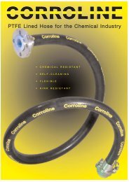
Funzionamento<br />
Working<br />
aria<br />
air<br />
fig.1<br />
fig.2<br />
aria<br />
air<br />
Fig. 1 - Valvola chiusa<br />
L’otturatore a doppia sede garantisce una sicura separazione<br />
tra parte superiore e parte inferiore del corpo valvola.<br />
Durante la fase di valvola chiusa è possibile effettuare<br />
una sterilizzazione della camera tra le due sedi, per mezzo<br />
delle due valvole poste sul corpo valvola, le quali hanno<br />
anche il compito di evidenziare una eventuale rottura della<br />
guarnizioni.<br />
Fig. 1 - Closed Valve<br />
The double seat shutter gives a perfect separation between<br />
the product lines, creating a chamber among them. The<br />
duty of the two auxiliary valves normally open equipped<br />
on the house, is to avoid any mixing of products and to<br />
ensure a leakage detection too. In the closed position, sterilisation<br />
or cleaning is allowed between the seats, by the<br />
two auxiliary valves.<br />
Fig. 2 - Valvola aperta<br />
Durante la fase di apertura della valvola le due valvole<br />
minori poste sul corpo valvola si chiudono, garantendo<br />
l’impossibilità che il liquido di lavaggio possa entrare in<br />
contatto con il prodotto.<br />
Fig. 2 - Open Valve<br />
In the opening phase of the double seat shutter, the two<br />
auxiliary valves closes automatically, avoiding any trespassing<br />
of CIP into the product.<br />
8
Pressioni massime di tenuta<br />
Maximum seal pressures (Bar/Psi)<br />
DN<br />
25 -1” 108 10/145 10/145<br />
32 108 10/145 10/145<br />
40-1”1/2 108 10/145 10/145<br />
50 130 10/145 10/145<br />
65 - 2”1/2<br />
80 - 3”<br />
100<br />
Presione circuito valvole ausiliarie P3= 6bar / 87psi<br />
Auxiliary valves circuit pressure P3= 6bar / 87psi<br />
D (mm)<br />
alesaggio / bore<br />
130 6.4/92 10/145<br />
156 10/145 10/145<br />
156 8.6/124 5.7/82<br />
207<br />
156 7.5/108 4.7/68<br />
207<br />
P1 (bar / psi)<br />
S.E. N.C. / S.A. N.C.<br />
P2 (bar / psi)<br />
DN<br />
25 -1” 108 10/145 9.5/138<br />
32 108 10/145 9.5/138<br />
40-1”1/2 108 10/145 9.5/138<br />
50 130 10/145 10/145<br />
65 - 2”1/2<br />
80 - 3”<br />
100<br />
Presione circuito valvole ausiliarie P3= 6bar / 87psi<br />
Auxiliary valves circuit pressure P3= 6bar / 87psi<br />
D (mm)<br />
alesaggio / bore<br />
130 10/145 6.5/94<br />
156 10/145 7.5/109<br />
156 10/145 5/72<br />
207<br />
156 10/145 4/58<br />
207<br />
P1 (bar / psi)<br />
D.E. N.C. / D.A. N.C.<br />
P2 (bar / psi)<br />
Legenda<br />
DN= Diametro nominale<br />
S.E. N.C.: Valvola normalmente chiusa con attuatore<br />
a semplice effetto (molla chiude/aria apre)<br />
D.E. N.C.: Valvola normalmente chiusa con attuatore a doppio effetto<br />
(aria e molla chiude/aria apre)<br />
Key<br />
DN= Nominal diameter<br />
S.A.N.C.: Valve normally closed with single acting<br />
actuator (air opens / spring closes)<br />
D.A. N.C.: Valve normally closed with double acting actuator<br />
(air opens / air and spring closes)<br />
9
<strong>ZAW</strong><br />
Raccomandazioni<br />
Disclaimer<br />
1. Tutte le affermazioni, le indicazioni e le notizie<br />
tecniche qui riportate sono basate sui dati di prove<br />
che riteniamo attendibili, ma non riferibili ad ogni<br />
possibile utilizzo del prodotto. Dal momento che le<br />
condizioni d’uso e di applicazione sono al di fuori del<br />
nostro controllo, l’Acquirente deve preventivamente<br />
accertare l’idoneità del prodotto all’uso al quale<br />
intende destinarlo, assumendo ogni rischio e<br />
responsabilità derivante dall’uso stesso. Bardiani<br />
<strong>Valvole</strong> S.p.A. non si assume responsabilità per alcun<br />
incidente, perdita o danno, diretto o consequenziale<br />
derivante dall’uso o dall’impossibilità d’uso del<br />
prodotto. Nessuno è autorizzato a concedere garanzie<br />
maggiori o diverse da quelle qui riportate.<br />
2. Raccomandiamo ai nostri clienti di consultare sempre i<br />
nostri collaboratori tecnici-commerciali per richiedere<br />
informazioni specifiche in merito alle caratteristiche<br />
tecniche dei nostri prodotti.<br />
3. Le raffigurazioni, tutte di valore generale e non<br />
vincolante, possono non corrispondere alle reali<br />
condizioni dei prodotti.<br />
4. Bardiani <strong>Valvole</strong> S.p.A. si riserva in qualsiasi momento<br />
e senza preavviso di modificare e/o aggiornare i dati,<br />
i disegni e le informazioni riportate nel presente<br />
documento<br />
5. Quanto riportato sulla presente pubblicazione si<br />
riferisce a prodotti di nostra normale produzione e<br />
non può in alcun caso essere un riferimento di base<br />
per prodotti eseguiti su specifiche richieste.<br />
6. Bardiani <strong>Valvole</strong> S.p.A. non è responsabile per i vizi<br />
e/o i difetti derivanti da installazione del prodotto<br />
non in conformità a quanto indicato nel “Manuale di<br />
istruzioni uso e manutenzione” o comunque derivanti<br />
da installazione non corretta o impropria o da un uso<br />
non corretto e/o improprio del prodotto.<br />
7. Bardiani <strong>Valvole</strong> S.p.A. non è responsabile per vizi<br />
e/o difetti del prodotto derivanti da un trasporto<br />
non corretto e/o derivanti da una impropria e/o<br />
non idonea conservazione e/o manutenzione dello<br />
stesso.<br />
8. Bardiani <strong>Valvole</strong> S.p.A. non è responsabile per difetti<br />
e/o vizi del prodotto dovuti a manomissioni e/o a<br />
interventi effettuati da personale non qualificato<br />
professionalmente, così come non è responsabile per<br />
i danni provocati da urti, ammaccamenti, incuria,<br />
negligenza ed in genere cause non imputabili a difetti<br />
di costruzione, fabbricazione e difetti di materiale.<br />
10<br />
1. All the statements, indications and technical data<br />
listed in this document are based on technical tests<br />
carried out by Bardiani <strong>Valvole</strong> S.p.A.. However<br />
accurate and reliable, such tests do not reflect all<br />
possible circumstances under which the products<br />
may be used. It is therefore advisable that the<br />
Buyer should always ascertain the suitability of the<br />
product in its application. The Buyer will be entirely<br />
liable for all risks and damages incurred by said<br />
products. Bardiani <strong>Valvole</strong> S.p.A. are not liable for<br />
any accident, loss or damage incurred, whether they<br />
be directly or indirectly caused by the use or misuse<br />
of the products. No further guarantees other than<br />
those stated in this document shall be granted.<br />
2. All our customers are advised to consult our<br />
technicians as well as our offices who will supply all<br />
information pertaining the technical characteristics<br />
of our products.<br />
3. The pictures contained in this document are<br />
intended to be general representations. They are<br />
not to be intended either legally binding or detailed<br />
representations of our products.<br />
4. Bardiani <strong>Valvole</strong> S.p.A. reserve the right at any time<br />
and with no further notice to amend and up-date<br />
the technical data, designs and the information<br />
contained in this document.<br />
5. The data and statements listed in this document only<br />
refer to our standard products. They do not apply<br />
in any case to any tailor-made products that might<br />
have been purchased by the customers.<br />
6. Bardiani <strong>Valvole</strong> S.p.A. are not liable for any defects<br />
or faults resulting from the incorrect installation of<br />
their products. Such installation is to be carried out<br />
in full compliance with the instructions contained<br />
in the “Manual of Instructions for the Use and<br />
Maintenance of the Product”. Bardiani <strong>Valvole</strong> S.p.A.<br />
are not liable for any defects or faults resulting from<br />
the incorrect use of their products.<br />
7. Bardiani <strong>Valvole</strong> S.p.A. are not liable for any<br />
defects or faults resulting from the incorrect<br />
transportation and/or incorrect storage and/or<br />
incorrect maintenance of their products.<br />
8. Bardiani <strong>Valvole</strong> S.p.A. cannot accept any liability<br />
for any faults or damages deriving from mishandling<br />
of the products and/or interventions carried out<br />
by unqualified personnel. No liability is accepted<br />
for damages caused by hits, dents, carelessness,<br />
negligence or any other any acts that cannot be<br />
considered as construction faults or faults related<br />
to the materials used in production.
I-CAT-<strong>ZAW</strong>-0507<br />
11
Bardiani <strong>Valvole</strong> s.p.a. via G. di Vittorio, 50-52, 43045 Fornovo di Taro (PR) Italy<br />
Tel +39.0525.400044 Fax +39.0525.3408<br />
e-mail: bardiani@bardiani.com www.bardiani.com<br />
www.bardiani.eu