bridge 4400 can - Bis Alarmes
bridge 4400 can - Bis Alarmes
bridge 4400 can - Bis Alarmes

Create successful ePaper yourself
Turn your PDF publications into a flip-book with our unique Google optimized e-Paper software.
BRIDGE <strong>4400</strong> CAN<br />
ISTRUZIONI COMPLETE<br />
COMPLETE INSTRUCTION
1 - LEGENDA E CONTENUTO DEL KIT / LEGENDA AND KIT CONTENTS.<br />
Centralina<br />
Central unit<br />
Centrale<br />
Centralita<br />
Central<br />
Çëåêôñïíéêüò åãêÝöáëïò<br />
Centrální jednotka<br />
Styrenhet<br />
Sentralenhet<br />
Central<br />
Steuergerät<br />
Cablaggio<br />
Wiring harness<br />
Câblage<br />
Cableado<br />
Conjunto de fios<br />
Êáëùäßùóç<br />
Kabeláž<br />
Kablar<br />
Ledningsnett<br />
Kabler<br />
Leitungssatz<br />
Sacchetto accessori<br />
Fittings bag<br />
Sachet des accessoires<br />
Bolsa de accesorios<br />
Saco de acessórios<br />
Óáêßäéï ìå áîåóïõÜñ<br />
Sáèek pøislušenstvím<br />
Tillbehörspåse<br />
Pakke med monteringsdeler<br />
Pose med tilbehør<br />
Zubehör<br />
Sensori ultrasuoni<br />
Sensor transducers<br />
Capteurs à ultrasons<br />
Sensores a ultrasonido<br />
Detectores de ultra-sons<br />
ÁéóèçôÞñáò õðåñÞ÷ùí<br />
Ultrazvukové snímaèe<br />
Ultraljudssensorer<br />
Ultralydsensorer<br />
Ultralydsfølere<br />
Ultraschallsensoren<br />
Sirena autoalimentata<br />
Siren with backup battery<br />
Sirène autoalimentée<br />
Sirena autoalimentada<br />
Sirene auto-alimentada<br />
Áõôïôñïöïäïôïýìåíç óåéñÞíá<br />
Siréna s nezávislým napájením<br />
Självförsörjande sirén<br />
Sirene med selvmatingsbatteri<br />
Sirene med batteri<br />
Sirene mit back up Batterie<br />
Loudspeaker<br />
Loudspeaker<br />
Sirène non autoalimentée<br />
Sirena no autoalimentada<br />
Sirene não auto-alimentada<br />
Ìç áõôïôñïöïäïôïýìåíç óåéñÞíá<br />
Siréna bez vlastního napájení<br />
Ej självförsörjande sirén<br />
Sirene uten selvmatingsbatteri<br />
Sirene uden batteri<br />
Sirene ohne back up Batterie<br />
Pannello di controllo<br />
Control panel<br />
Tableau de commande<br />
Panel de control<br />
Painel de controlo<br />
Ðßíáêáò åëÝã÷ïõ<br />
Ovládací panel<br />
Kontrollpanel<br />
Kontrollpanel<br />
Styrepanel<br />
Emergency Panel<br />
Manuale utente/installatore<br />
User/installation manual<br />
Manuel utilisateur/Installateur<br />
Manual del usuario/instalador<br />
Manual de uso/instalação<br />
Åã÷åéñßäéï ÷ñÞóôç<br />
Návod pro uživatele/instalatéra<br />
Användar-/installattionshandbok<br />
Brukermanual/installatørmanual<br />
Bruger-/installatørmanual<br />
Montage und Bedienungsanleitung<br />
Pin Code Card<br />
Pin Code Card<br />
Carte Code PIN<br />
Tarjeta de código PIN<br />
Cartão do código PIN<br />
Pin code card<br />
Karta s pin kódem<br />
Pin code card<br />
PIN-kodekort<br />
Pin-kode card<br />
Pin Code Karte<br />
Vetrofania<br />
Warning sticker<br />
Vitrauphanie<br />
Calcomanía de advertencia<br />
Aviso autocolante<br />
Áõôïêüëëçôá ãéá ôá ôæÜìéá<br />
Fólie na sklo s upozornìními<br />
Varningsetikett<br />
Advarselssticker<br />
Advarselsmærkat<br />
Cobra Fensteraufkleber<br />
8772<br />
Radiocomando<br />
Radio controls<br />
Radiocommande<br />
Radiomando<br />
Comando por rádio<br />
Ôçëå÷åéñéóìüò<br />
Rádiové ovládání<br />
Fjärrkontroller<br />
Fjernkontroller<br />
Fjernbetjeninger<br />
Fernbedienungen<br />
Cablaggio sirena<br />
Siren wiring harness<br />
Câblage sirène<br />
Cableado de sirena<br />
Conjunto de fios da sirene<br />
Êáëùäßùóç óåéñÞíáò<br />
Kabeláž sirény<br />
Sirénkablar<br />
Ledningsnett sirene<br />
Sirenekabler<br />
Leitungssatz Sirene<br />
Dima di foratura<br />
Drilling mask<br />
Gabarit de perçage<br />
Es<strong>can</strong>tillón para perforar<br />
Es<strong>can</strong>tilhão para perfuração<br />
‘Åëáóìá ôñõðÞìáôïò<br />
Vrtací šablona<br />
Borrningsmall<br />
Hullmal<br />
Hulskabelon<br />
Bohrschablone<br />
Staffa<br />
Bracket<br />
Patte de fixation<br />
Estribo<br />
Presilha<br />
Âñá÷ßïíáò<br />
Tømen<br />
Bygel<br />
Bøjle<br />
Bøjle<br />
Halter<br />
2771<br />
Driver card<br />
Driver card<br />
Carte de circuit de commande<br />
Driver card<br />
Cartão do condutor<br />
Driver card<br />
Driver card<br />
Driver card<br />
Driver card<br />
Driver card<br />
Driver card<br />
2<br />
BRIDGE <strong>4400</strong>
w.cobra-at.com<br />
KIT<br />
#<br />
AK 4485<br />
*<br />
3<br />
3<br />
3<br />
3<br />
3<br />
3<br />
3<br />
3<br />
3<br />
3<br />
3<br />
3<br />
3<br />
3<br />
AK 4435<br />
3<br />
3<br />
3<br />
3<br />
3<br />
3<br />
3<br />
3<br />
3<br />
3<br />
3<br />
3<br />
3<br />
3<br />
AK 4430<br />
3<br />
3<br />
3<br />
3<br />
3<br />
3<br />
3<br />
3<br />
3<br />
3<br />
3<br />
3<br />
AK 4425<br />
3<br />
3<br />
3<br />
3<br />
3<br />
3<br />
3<br />
3<br />
3<br />
3<br />
3<br />
3<br />
3<br />
3<br />
AK 4415<br />
3<br />
3<br />
3<br />
3<br />
3<br />
3<br />
3<br />
3<br />
3<br />
3<br />
3<br />
AK 4410<br />
3<br />
3<br />
3<br />
3<br />
3<br />
3<br />
3<br />
3<br />
3<br />
3<br />
AK 4405<br />
3<br />
3<br />
3<br />
3<br />
3<br />
3<br />
3<br />
3<br />
3<br />
3<br />
3<br />
AC 4436<br />
3<br />
3<br />
3<br />
#<br />
3<br />
3<br />
3<br />
3<br />
3<br />
3<br />
3<br />
AC 4416<br />
3<br />
3<br />
3<br />
#<br />
3<br />
3<br />
3<br />
3<br />
∗ = CAN L with single wire - CAN L con filo singolo.<br />
# = OPZIONALE - OPTIONAL.<br />
BRIDGE <strong>4400</strong><br />
3
Gentile cliente,<br />
nel ringraziarla per la scelta fatta la informiamo che questo prodotto è un sistema di allarme tecnologicamente avanzato, rispondente agli<br />
standards di prestazioni definiti dalle case automobilistiche e conforme alle direttive comunitarie.<br />
A Lei, gentile utente, dopo l’installazione del sistema sono stati consegnati i radiocomandi ed il manuale utente che contiene anche la dichiarazione<br />
di conformità del prodotto ed il relativo certificato di installazione.<br />
Il manuale è suddiviso in:<br />
I<br />
Page<br />
Capitolo<br />
2/3 _____ (1) LEGENDA E CONTENUTO DEL KIT.<br />
5 _____ (2) INFORMAZIONI.<br />
6 _____ (3) INTRODUZIONE.<br />
7 _____ (4) COMPLEMENTI DI PROTEZIONE.<br />
7 _____ (5) CONFIGURAZIONE CAN BUS.<br />
8 _____ (6) POSIZIONAMENTO ELEMENTI DI SISTEMA.<br />
9 _____ (7) ELENCO FUNZIONI STANDARD.<br />
9 _____ (7.2) ELENCO FUNZIONI PROGRAMMABILI.<br />
11 ______ (7.4) FUNZIONALITA’ PULSANTI.<br />
12 ______ (8) ABBINAMENTO MODULI, SIRENA 4310, ALLARME ICD31.<br />
12 ______ (9) PROGRAMMAZIONE.<br />
13 ______ (10) FUNZIONI <strong>4400</strong>.<br />
14 ______ (11) INSERIMENTO E DISINSERIMENTO.<br />
15 ______ (12) MEMORIA DI ALLARME.<br />
16 ______ (13) EMERGENZA.<br />
17 ______ (14) (15) CARATTERISTICHE TECNICHE E PROCEDURA<br />
18 ______ (16) (16.2) SOSTITUZIONE BATTERIE E RICERCA GUASTI<br />
da 36 a 52 _________<br />
GARANZIE E SCHEMI.<br />
Legga il manuale con attenzione: trarrà la massima soddisfazione dal prodotto acquistato.Le consigliamo inoltre di conservare questo manuale insieme ai<br />
documenti dell’auto per una più facile consultazione in caso di necessità. Qualora si manifesti un problema non risolvibile, si rivolga direttamente<br />
al suo installatore di fiducia.<br />
4<br />
I<br />
MANUALE COMPLETO BRIDGE <strong>4400</strong>
2 - INFORMAZIONI.<br />
Il sistema è dotato della funzione di auto apprendimento, che permette di semplificare tutte le operazioni di aggiunta o sostituzione di radiocomandi<br />
/ Driver Card solo con il consenso dell’utente.<br />
Per la procedura fare riferimento al manuale Pag. 16 Cap. 13.<br />
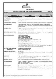
2.1 - Codice personale PIN.<br />
Ogni sistema della serie BRIDGE <strong>4400</strong> è provvisto di un Pin Code utilizzabile per il disinserimento di emergenza.<br />
Questo è un esempio della PIN CODE CARD<br />
(PIN CODE programmato da fabbrica):<br />
www.cobra-at.com<br />
INCOLLARE ETICHETTA<br />
PIN CODE<br />
4C4415A2A<br />
S/N 0003 050524<br />
CODICE PERSONALE PIN<br />
PIN<br />
CODE<br />
1122<br />
Vi raccomandiamo di posizionare l’etichetta adesiva PIN CODE, che troverete sul retro della centralina,<br />
nell’apposita PIN CODE CARD .<br />
BRIDGE <strong>4400</strong> MANUALE COMPLETO<br />
I<br />
5
3 - INTRODUZIONE.<br />
I sistemi di allarme anti-intrusione della serie BRIDGE <strong>4400</strong> sono dotati di un’interfaccia seriale Can (Controller Area Network) che permette il<br />
colloquio con la rete dati della vettura e sono controllati, in tutte le versioni, dal radiocomando originale del veicolo, oppure, ove previsto, anche<br />
da un radiocomando o una Driver Card Cobra con codici ad alta sicurezza. Questa tecnologia offre un elevatissimo grado di protezione contro<br />
ogni tentativo di riproduzione del codice.<br />
Il radiocomando Cobra permette di azionare il sistema ad una distanza di 5 - 10 metri dal veicolo.<br />
La Driver Card Cobra permette di disinserire il blocco motore e l’antirapina ad una distanza di 1 - 5 metri dal veicolo.<br />
In alcune circostanze si può verificare una riduzione della portata a causa di interferenze generate da altre fonti (es. radioamatori che operano<br />
sulla stessa frequenza).<br />
In caso di mancato funzionamento avvicinarsi il più possibile al veicolo. Se è prevista la chiusura confort dei vetri da radiocomando, Vi<br />
raccomandiamo di effettuare questa operazione restando vicini al veicolo in modo tale che questa azione si verifichi in condizioni di sicurezza.<br />
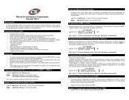
La protezione della vostra vettura è assicurata da:<br />
Modello<br />
PROTEZIONE<br />
ANTIAVVIAMENTO<br />
PROTEZIONE<br />
VOLUMETRICA<br />
PROTEZIONE<br />
PERIMETRICA<br />
PROTEZIONE<br />
TAGLIO CAVI<br />
AK 4485<br />
AK 4435<br />
AK 4430<br />
AK 4425<br />
AK 4415<br />
AK 4410<br />
AK 4405<br />
AC 4436<br />
AC 4416<br />
<br />
<br />
<br />
<br />
<br />
<br />
<br />
<br />
<br />
<br />
<br />
<br />
<br />
<br />
<br />
<br />
#<br />
#<br />
<br />
<br />
<br />
<br />
<br />
<br />
<br />
<br />
<br />
<br />
<br />
<br />
<br />
<br />
6<br />
# = OPZIONALE.<br />
I<br />
MANUALE COMPLETO BRIDGE <strong>4400</strong>
4 - COMPLEMENTI DI PROTEZIONE.<br />
Il sistema di allarme da lei acquistato può essere completato, per<br />
aumentare il livello di protezione offerto al suo veicolo, dai seguenti<br />
moduli:<br />
5452: modulo antisollevamento.<br />
A sistema di allarme inserito, attraverso un sensore speciale,<br />
l’antisollevamento protegge il veicolo dai tentativi di traino e<br />
sollevamento e di conseguenza dai furti di accessori di valore come<br />
ad esempio i cerchi in lega.<br />
5462: modulo iperfrequenza.<br />
A sistema di allarme inserito, tramite l’emissione di raggi a<br />
iperfrequenza, il modulo, posizionato e nascosto all’interno dell’auto,<br />
assicura la protezione volumetrica dell’abitacolo.<br />
2980: modulo alzacristalli.<br />
All’ inserimento del sistema, i vetri elettrici del vostro veicolo si<br />
chiudono automaticamente.<br />
8509: modulo a 2 blocchi motore.<br />
A sistema di allarme inserito, tramite 2 relais inseriti nel modulo è<br />
possibile realizzare una doppia interruzione del circuito di avviamento.<br />
ICD 213X: sistema di allarme satellitare.<br />
Questo sistema comunica con il Bridge <strong>4400</strong> tramite una linea seriale<br />
dedicata (Cobra Bus) ed è in grado di fornire informazioni di tentata<br />
effrazione alla centrale operativa.<br />
5 - Configurazione Can Bus.<br />
I prodotti della serie Bridge <strong>4400</strong> sono studiati per sopportare diverse<br />
piattaforme auto (brand) dotate di interfaccia Can (controller area<br />
network). Tutti i sistemi ad eccezione del 4485 hanno di fabbrica la<br />
selezione delle Brand Volkswagen, mentre il 4485 ha la selezione<br />
della Brand Opel. Se si desidera utilizzare un’altra brand occorre<br />
obbligatoriamente avere:<br />
- Il software Morpheus scaricabile del sito www.cobra-at.com<br />
(Area Professionale).<br />
BRIDGE <strong>4400</strong> MANUALE COMPLETO<br />
I<br />
- L’interfaccia tra il pc e il sistema di allarme (cod. AV0088STAAD).<br />
- Un pc con la possibilità di un collegamento seriale.<br />
IMPORTANTE: Se non si utilizza la brand programmata da fabbrica,<br />
la sua configurazione e la selezione del modello sono indispensabili<br />
per il funzionamento del sistema. Nel caso in cui non si utilizzi la<br />
brand programmata da fabbrica, seguire le istruzioni riportate qui di<br />
seguito:<br />
- durante i primi 5 s, dopo che il sistema viene alimentato (segnalati<br />
dal lampeggio veloce del LED), tenere premuto il pulsante del<br />
pannello ed attendere il suo spegnimento;<br />
- a questo punto rilasciare il pulsante;<br />
- una volta rilasciato il pulsante, il LED lampeggerà ad indicare<br />
l’ingresso nella selezione del modello del veicolo, per un numero<br />
di volte pari alla selezione programmata da fabbrica (es. 3<br />
lampeggi).<br />
Il numero di lampeggi corrisponde al numero di riga della tabella<br />
Brand Matrix inserita nella confezione. Ogni riga della tabella può<br />
corrispondere ad uno o più modelli auto della Brand.<br />
Se si desidera cambiare modello di veicolo, occorre:<br />
- premere brevemente il pulsante del pannello di controllo;<br />
- ogni pressione incrementa di una riga;<br />
- nel caso in cui si sia arrivati all’ultima riga disponibile, con<br />
un’ulteriore pressione sul pulsante ripartirà il conteggio dalla riga<br />
uno della Brand;<br />
- una volta posizionati sulla riga (modello auto desiderato), occorre<br />
attendere che il sistema finisca di segnalare con cinque cicli la<br />
riga selezionata;<br />
- l’uscita dalla programmazione del modello auto è segnalata dallo<br />
spegnimento del LED.<br />
Verificare la funzionalità della configurazione prescelta, inserendo e<br />
disinserendo il sistema.<br />
7
6 - POSIZIONAMENTO DEGLI ELEMENTI DEL SISTEMA.<br />
Tutti gli elementi del sistema devono essere posti in posizioni<br />
difficilmente accessibili e lontane da fonti di calore.<br />
6.1 - Centrale di allarme.<br />
La centrale di allarme deve essere fissata all’interno dell’abitacolo<br />
avendo cura di orientare il connettore principale verso il basso.<br />
6.4 - Sensore volumetrico ad ultrasuoni .<br />
I sensori ultrasuoni devono essere installati sulla parte alta dei<br />
montanti del parabrezza anteriore o del lunotto posteriore avendo<br />
cura che non vengano coperti quando le alette parasole sono<br />
abbassate. Determinare il corretto orientamento delle testine durante<br />
l’esecuzione del test funzionale del sistema. Questo sistema<br />
incorpora un sensore di tipo autoregolante che si adatta ad ogni tipo<br />
di veicolo calcolando automaticamente la volumetria dell’abitacolo.<br />
6.2 - Sirena autoalimentata.<br />
Da fissare all’interno del<br />
vano motore avendo cura di<br />
orientarla come indicato.<br />
O.K.<br />
K.O.<br />
6.5 - Pannello di controllo.<br />
Il pannello di controllo viene installato normalmente sul cruscotto in<br />
modo che il pulsante sia facilmente raggiungibile ed il LED visibile<br />
dall’esterno del veicolo, infatti oltre ad avere una funzione deterrente<br />
il pannello (LED + pulsante) viene utilizzato durante le operazioni di<br />
programmazione e per quelle di riconoscimento dell’utente.<br />
6.6 - Pulsante cofano.<br />
6.3 - Loudspeaker.<br />
Il Loudspeaker deve essere fissato<br />
all’interno del vano motore avendo cura di<br />
fissarlo mediante le apposite viti ad una<br />
superficie metallica che favorisca la<br />
dissipazione termica del magnete.<br />
Ø 3 mm.<br />
1<br />
4<br />
L’installazione del pulsante cofano è indispensabile, se non presente<br />
d’origine o non gestito via Can-Bus, per consentire l’accesso alle<br />
procedure di programmazione dell’allarme ed avere la protezione<br />
del vano motore. Ad installazione ultimata controllare che il pulsante<br />
non vada a premere su pannelli fonoassorbenti o sulla lamiera esterna<br />
della carrozzeria, poiché questi materiali potrebbero deformarsi nel<br />
tempo.<br />
6.7 - Antenna (solo per 442X, 443X e 4485).<br />
8<br />
3<br />
2<br />
Il posizionamento dell’antenna è fondamentale ai fini del buon<br />
funzionamento del sistema di radiocomandi e Driver Card. Il cavo<br />
non deve essere tagliato, arrotolato, collegato ad altro cavo o alla<br />
carrozzeria e deve essere mantenuto separato dal cablaggio.<br />
Posizionare l’antenna in modo che sia distante almeno 20 mm. da<br />
parti metalliche.<br />
I<br />
MANUALE COMPLETO BRIDGE <strong>4400</strong>
7 - ELENCO FUNZIONI.<br />
7.1 - Funzioni standard.<br />
Di seguito sono elencate le caratteristiche funzionali principali<br />
dell’allarme.<br />
• Inserimento/disinserimento per mezzo dei radiocomandi originali<br />
del veicolo (tutte le versioni).<br />
• Inserimento/disinserimento per mezzo dei radiocomandi Cobra<br />
(solo versioni 442x,443x e 4485).<br />
• Protezione volumetrica dell’abitacolo con sensore ad ultrasuoni<br />
che non necessita di regolazioni della sensibilità.<br />
• Protezione perimetrica con funzione diagnostica nei primi 30 s<br />
dall’inserimento. Se una porta, cofano o baule vengono aperti<br />
l’avvisatore acustico emette un segnale sonoro nei primi 30 s o<br />
genera un ciclo di allarme passato tale tempo.<br />
• Il tempo di ogni ciclo di allarme è di 30 s. Gli indicatori di direzione<br />
lampeggiano.<br />
• LED di indicazione dello stato del sistema con funzione memoria<br />
di avvenuti allarmi.<br />
• Esclusione ultrasuoni manuale (pannello di controllo) o automatica<br />
Can Bus da software (se prevista).<br />
• Disinserimento di emergenza tramite Pin Code.<br />
• Protezione taglio cavi (sirena autoalimentata).<br />
• Comando del sistema di chiusura centralizzata (solo versioni 442x,<br />
443x e 4485).<br />
• Blinker inserimento/disinserimento.<br />
• Inserimento antidistrazione.<br />
• Inserimento passivo.<br />
• Blocco motore passivo (solo versioni 442x, 443x e 4485).<br />
• Antirapina automatica.<br />
• Funzione garage.<br />
7.2 - Elenco funzioni programmabili.<br />
• Regolazione volume o esclusione buzzer.<br />
• Attivazione inserimento passivo.<br />
• Attivazione antidistrazione.<br />
• Abilitazione comando chiusure centralizzate con antidistrazione<br />
(solo per 442x-443x e 4485).<br />
• Attivazione blocco motore passivo (solo per 442x-443x e 4485).<br />
• Attivazione antirapina.<br />
• Abilitazione funzione garage.<br />
• Polarità ingresso porta guida (gestita generalmente in automatico<br />
dalla piattaforma Can).<br />
• Polarità ingresso baule (gestita generalmente in automatico dalla<br />
piattaforma Can).<br />
• Attivazione uscita loudspeaker o clacson.<br />
• Uscita clacson fissa o intermittente.<br />
• Abilitazione comando chiusura confort (28 s).<br />
• Abilitazione comando chiusura confort manuale dal tasto A<br />
radiocomando Cobra.<br />
• Blocco selezione Can.<br />
7.3 - Descrizione delle funzioni programmabili.<br />
• Regolazione volume o esclusione buzzer.<br />
Attivata<br />
Questa funzione permette la regolazione del volume del segnale<br />
acustico di inserimento e disinserimento o la sua completa<br />
disattivazione.<br />
Importante: la sua attivazione nei paesi CE è vietata.<br />
• Attivazione inserimento passivo.<br />
Attivata<br />
Disattivata<br />
Disattivata<br />
Questa funzione permette l’inserimento automatico del sistema dopo<br />
aver rilevato lo spegnimento del motore e l’apertura e la chiusura<br />
della porta lato guida entro 30 s.<br />
BRIDGE <strong>4400</strong> MANUALE COMPLETO<br />
I<br />
9
10<br />
• Attivazione antidistrazione.<br />
Attivata<br />
Questa funzione permette l’inserimento automatico del sistema se<br />
dopo 115 s dal disinserimento nessuna porta viene aperta.<br />
• Abilitazione comando chiusure centralizzate con<br />
antidistrazione.<br />
Attivata<br />
Questa funzione permette l’attivazione del comando di chiusura<br />
all’l’inserimento automatico del sistema se dopo 115 s dal<br />
disinserimento nessuna porta viene aperta.<br />
• Abilitazione blocco motore passivo.<br />
Attivata<br />
Questa funzione permette l’attivazione del blocco motore se entro<br />
115 s dallo spegnimento del quadro non viene aperta la porta lato<br />
guida. Nel caso si ha a disposizione la Driver Card accesa,<br />
nell’abitacolo, questa funzione viene automaticamente esclusa.<br />
Se si vuole disinserire il sistema occorre effettuare prima l’inserimento<br />
e poi il disinserimento.<br />
• Attivazione antirapina automatica.<br />
Attivata<br />
Disattivata<br />
Disattivata<br />
Disattivata<br />
Disattivata<br />
Questa funzione permette all’utente del veicolo di essere riconosciuto<br />
entro 120 s dall’accensione del quadro. Per essere riconosciuti<br />
occorre digitare le prime due cifre del Pin Code o avere una Driver<br />
Card abilitata dal sistema. Una volta riconosciuti, l’utilizzo della vettura<br />
è consentito in ogni caso fino al successivo spegnimento del quadro<br />
o all’apertura/chiusura porta con quadro acceso. Se il codice non<br />
viene trasferito correttamente, a 30 s dal termine del tempo di<br />
riconoscimento il LED sul pannello di controllo comincia a<br />
lampeggiare velocemente fino al termine di tale tempo. Al termine<br />
dei 120 s il sistema genera una sequenza di 9 cicli di allarmi sonori<br />
e visivi. Il blocco motore si attiverà al successivo tentativo di<br />
avviamento del motore. Per disinserire il blocco motore durante la<br />
fase di allarme occorre digitare le quattro cifre del Pin Code o avere<br />
la Driver Card abilitata dal sistema.<br />
IMPORTANTE. La funzione è disabilitata da fabbrica in conformità<br />
alla normativa Europea e la sua attivazione invalida la conformità<br />
alle prescrizioni di legge.<br />
• Attivazione funzione garage.<br />
Attivata<br />
Questa funzione permette l’esclusione temporanea di tutti gli<br />
inserimenti automatici se l’utente desidera lasciare le chiavi del<br />
veicolo ad altre persone senza fornire loro i radiocomandi. Una volta<br />
abilitata la funzione vengono permessi 10 cicli massimi di avviamento<br />
senza alcuna forma di attivazione automatica.<br />
Una volta attivata la funzione in fase di programmazione per il suo<br />
funzionamento occorre:<br />
- aprire la porta lato guida e ruotare la chiave di avviamento<br />
in ON,<br />
- digitare le quattro cifre del Pin Code,<br />
- 1 lampeggio degli indicatori di direzione indica che la<br />
funzione garage è attiva.<br />
Se si vuole disattivare la funzione volontariamente occorre:<br />
- aprire la porta lato guida e ruotare la chiave di avviamento<br />
in ON,<br />
- digitare le quattro cifre del Pin Code,<br />
- 5 lampeggi degli indicatori di direzione indica che la<br />
funzione garage è disattivata.<br />
I<br />
Disattivata<br />
MANUALE COMPLETO BRIDGE <strong>4400</strong>
• Polarità ingresso porta lato guida.<br />
Positiva<br />
Questa funzione definisce la polarità dell’ingresso porta lato guida,<br />
quando si utilizza il filo GRIGIO - NERO (vedi scheda tecnica).<br />
• Polarità ingresso baule.<br />
Positiva<br />
Questa funzione definisce la polarità dell’ingresso baule, quando si<br />
utilizza il filo GIALLO - NERO (vedi scheda tecnica).<br />
• Attivazione uscita loudspeaker o clacson.<br />
Clacson<br />
Questa funzione permette di azionare con un comando modulato il<br />
loudspeaker o con un comando negativo un clacson o altro dispositivo<br />
(es. Pager) dalla pos. 15 del connettore del cablaggio della centrale<br />
d’allarme (pos. libera).<br />
• Uscita fissa o intermittente.<br />
Fissa<br />
Negativa<br />
Negativa<br />
Loudspeaker<br />
Intermittente<br />
• Abilitazione comando chiusura confort manuale.<br />
Attivata<br />
Questa funzione permette, tenendo premuto il tasto A del<br />
radiocomando Cobra, di pilotare manualmente il comando di chiusura<br />
confort. Ciò e possibile solo per i sistemi dotati di radiocomando<br />
Cobra.<br />
• Blocco selezione piattaforme.<br />
Attivata<br />
Questa funzione permette al LED di lampeggiare velocemente<br />
per 5 s all’ alimentazione del sistema permettendo la selezione<br />
delle piattaforme CAN.<br />
7.4 - Funzionalita’ dei pulsanti del radiocomando Cobra (solo<br />
versioni 442x, 443x e 4485).<br />
Pulsante A<br />
Disattivata<br />
Disattivata<br />
B<br />
Inserisce l’allarme e il blocco motore.<br />
A<br />
Questa funzione permette di selezionare il tipo di segnale fisso o<br />
intermittente del loudspeaker o clacson.<br />
Pulsante B<br />
Disinserisce l’allarme e il blocco<br />
motore.<br />
B<br />
A<br />
• Abilitazione comando chiusura confort.<br />
Attivata<br />
Disattivata<br />
Questa funzione permette di avere un comando di 28 s sul filo VIOLA<br />
(pos. 23) del cablaggio della centrale d’allarme.<br />
BRIDGE <strong>4400</strong> MANUALE COMPLETO<br />
I<br />
11
8 - Abbinamento dei moduli / sirena 4310 / allarme satellitare<br />
ICD 213X su linea Cobra Bus.<br />
Sulla linea Cobra Bus (pin 10) è possibile abbinare i seguenti moduli<br />
aggiuntivi (Sirena 4310 / modulo antisollevamento / allarme satellitare<br />
ICD 213X / Blocco motore 8509), mediante procedura di<br />
programmazione:<br />
9 - PROGRAMMAZIONE<br />
PER ENTRARE IN PROGRAMMAZIONE<br />
A<br />
ALLARME<br />
DISINSERITO<br />
B<br />
C<br />
1. disinserire il sistema,<br />
2. entrare in programmazione mediante procedura dedicata<br />
per prodotto,<br />
3. passare dalla pagina 2 alla pagina 7 mediante l’attivazione<br />
e disattivazione del quadro (+15 ON / OFF),<br />
4. l’indicazione dell’avvenuta memorizzazione e fine<br />
programmazione viene segnalata da un lampeggio lungo<br />
degli indicatori di direzione.<br />
D<br />
OFF<br />
OFF<br />
ON<br />
ON<br />
IGN +15<br />
E<br />
F<br />
1 FLASH<br />
OK<br />
NOTA: in caso si colleghino 2 moduli 8509 occorre memorizzare,<br />
prima un modulo, uscire dalla programmazione e ripetere<br />
l’operazione per il secondo rientrando in programmazione.<br />
PER CAMBIARE TABELLA<br />
PER USCIRE<br />
Se viene scollegato un modulo dalla linea Cobra Bus, ripetere dal<br />
punto numero 1.<br />
OFF<br />
OFF<br />
ON<br />
ON<br />
NOTA: ad allarme disinserito, scollegando un modulo auto<br />
appreso dalla linea Cobra Bus, all’inserimento del sistema si<br />
avrà una segnalazione da 8 lampeggi a 12 degli indicatori di<br />
direzione e se attivato, si avranno da 8 a 12 segnalazioni del<br />
Buzzer.<br />
IGN +15<br />
PER CAMBIARE LINEA<br />
PER ATTIVARE/DISATTIVARE UNA FUNZIONE<br />
IMPORTANTE: se il KIT comprende la sirena autoalimentata 4310,<br />
non occorre eseguire l’abbinamento perchè è già abbinata in<br />
fabbrica.<br />
12<br />
I<br />
MANUALE COMPLETO BRIDGE <strong>4400</strong>
10 - TABELLE FUNZIONI <strong>4400</strong>.<br />
TABELLA FUNZIONI<br />
Lampeggio corto<br />
PAGINA 4<br />
Lampeggio lungo<br />
<strong>4400</strong><br />
NOTE<br />
Il volume del buzzer (inserimento<br />
disinserimento acustico) ha sette<br />
livelli di volume, arrivati al livello<br />
massimo se si digita ancora il<br />
pulsante sul pannello di controllo il<br />
volume riparte dal livello 0)<br />
NOTE<br />
Raggiungere la tabella 7 per<br />
confermare i dispositivi rilevati.<br />
IMPORTANTE<br />
Si raccomanda di non collegare<br />
l'antenna durante la fase di<br />
autoapprendimenta codici, per<br />
evitare che codici indesiderati<br />
possano essere memorizzati.<br />
5 lampeggi del blinker confermano<br />
l'avvenuta memorizzazione del<br />
nuovo Pin Code.<br />
PAGINA 1<br />
BUZZER<br />
PAGINA 2<br />
TABELLA FUNZIONI<br />
Vol +<br />
TABELLA FUNZIONI<br />
RICONOSCIMENTO DISPOSITIVI CAN BUS<br />
0 7<br />
Riconoscimento automatico delle periferiche collegate alla linea Cobra<br />
Bus (max 6 dispositivi).<br />
Digitando il PIN code si entra in autoapprendimento TX (max 4) 5 segnalazioni<br />
blinker.<br />
Entrando in questa riga la prima volta che si preme un tasto del radiocomando<br />
si <strong>can</strong>cellano tutti i codici precedentemente memorizzati e si memorizza il<br />
codice del radiocomando in uso. Per memorizzare altri radiocomandi o Driver<br />
Card è sufficiente ripetere l'operazione. Ogni volta che si apprende un codice<br />
nuovo il LED lampeggia una volta.<br />
Per cambiare il PIN code rispettare la seguente procedura:<br />
1) Digitare le 4 cifre del nuovo Pin Code.<br />
2) Spegnere e riaccendere il quadro.<br />
3) Ridigitare le 4 cifre del nuovo Pin Code.<br />
1 POLARITA' INGRESSO PORTE LATO GIUDA<br />
2 POLARITA' INGRESSO BAULE<br />
3 ATTIVAZIONE USCITA LOUDSPEAKER O CLACSON #<br />
4 USCITA FISSA O INTERMITTENTE<br />
5 ABILITAZIONE COMANDO CHIUSURA CONFORT<br />
6 ABILITAZIONE COMANDO CHIUSURA CONFORT MANUALE<br />
PAGINA 5<br />
PAGINA 6<br />
Lampeggio lungo<br />
NON DISPONIBILE<br />
NON DISPONIBILE<br />
CLACSON LOUDSPEAKER<br />
FISSA INTERMITTENTE<br />
ATTIVA DISATTIVA<br />
ATTIVA DISATTIVA<br />
* Se utilizzate questa funzione, assicuratevi che il sistema "Antischiacciamento"<br />
originale dell'alzavetri sia garantito. Disattiva per prodotti con radiocomando.<br />
# Per versioni 4410 e 4430 il default è 3) LOUDSPEAKER; 4) FISSA<br />
Lampeggio corto<br />
1 BLOCCO SELEZIONE PIATTAFORME ATTIVA DISATTIVA<br />
1 LIBERA<br />
TABELLA FUNZIONI<br />
TABELLA FUNZIONI<br />
*<br />
PAGINA 3<br />
1 INSERIMENTO PASSIVO<br />
2 INSERIMENTO ANTIDISTRAZIONE<br />
3 ATTIVAZIONE CHIUSURA CENTRALIZZATA DURANTE INSERIMENTO<br />
ANTIDISTRAZIONE<br />
4 BLOCCO MOTORE PASSIVO<br />
5 ABILITAZIONE FUNZIONE GARAGE<br />
6 ANTIRAPINA<br />
TABELLA FUNZIONI<br />
Lampeggio lungo<br />
ATTIVA<br />
ATTIVA<br />
ATTIVA<br />
ATTIVA<br />
ATTIVA<br />
ATTIVA<br />
Lampeggio corto<br />
DISATTIVA<br />
DISATTIVA<br />
DISATTIVA<br />
DISATTIVA<br />
DISATTIVA<br />
DISATTIVA<br />
PAGINA 7<br />
TABELLA FUNZIONI<br />
VISUALIZZAZIONE DISPOSITIVI COBRA BUS MEMORIZZATI<br />
1 SIRENA AUTOALIMENTATA<br />
2 MODULI ULTRASUONI<br />
3 ANTISOLLEVAMENTO<br />
4 IMMOBILIZER 1<br />
5 IMMOBILIZER 2<br />
6 KEY BOARD<br />
7 ICD<br />
Ogni tipo di dispositivo verrà<br />
identificato con un numero<br />
differente di lampeggi.<br />
La pausa tra una segnalazione e<br />
la successiva è di 2 s.<br />
BRIDGE <strong>4400</strong> MANUALE COMPLETO<br />
I<br />
13
11 - INSERIMENTO E DISINSERIMENTO.<br />
11.1 - Inserimento del sistema con radiocomando originale del<br />
veicolo (tutte le versioni).<br />
Premendo il pulsante di chiusura del radiocomando originale:<br />
- si bloc<strong>can</strong>o le porte,<br />
- la funzione buzzer è disabilitata attivabile solo nei paesi<br />
extra CE,<br />
- il LED si accende a luce fissa per i primi 25 s, poi lampeggia,<br />
- le protezioni diventano attive quando il LED inizia a<br />
lampeggiare.<br />
11. 2 - Inserimento del sistema con radiocomando Cobra (versioni<br />
442x, 443x,4485).<br />
Premendo il pulsante “A” del radiocomando Cobra:<br />
- si bloc<strong>can</strong>o le porte,<br />
- La funzione buzzer è disabilitata attivabile<br />
solo nei paesi extra CE.<br />
11. 3 - Inserimento del sistema con disinserimento volontario del<br />
sensore volumetrico e sensori esterni.<br />
Il disinserimento volontario del sensore volumetrico avviene<br />
rispettando la seguente procedura:<br />
1. premere il pulsante sul pannello di controllo<br />
entro 5 s dallo spegnimento del quadro.<br />
2. Tenere premuto il pulsante sul pannello di<br />
controllo fino a che il LED segnali:<br />
B<br />
A<br />
• con 1 flash l’avvenuta esclusione del sensore volumetrico<br />
del sistema,<br />
• con 2 flash l’avvenuta esclusione del sensore volumetrico<br />
del sistema e di eventuali moduli aggiuntivi (collegati<br />
sull’ingresso moduli).<br />
11.4 - Disinserimento del sistema con radiocomando originale<br />
del veicolo (tutte le versioni).<br />
Premendo il pulsante di apertura del radiocomando originale:<br />
- si bloc<strong>can</strong>o le porte,<br />
- la funzione buzzer è disabilitata attivabile solo nei paesi<br />
extra CE,<br />
- il LED si spegne,<br />
- le protezioni sono disabilitate.<br />
11.5 - Disinserimento del sistema con radiocomando Cobra<br />
(versioni 442x, 443x,4485).<br />
Premendo il pulsante “B” del radiocomando Cobra:<br />
- si sbloc<strong>can</strong>o le porte,<br />
- la funzione buzzer è disabilitata attivabile<br />
solo nei paesi extra CE,<br />
- il LED si spegne,<br />
- le protezioni sono disabilitate.<br />
11.6 - Disinserimento del blocco motore passivo e disattivazione<br />
inserimento funzione antirapina con Driver Card (dove<br />
prevista).<br />
Il riconoscimento automatico o la pressione del pulsante della Driver<br />
Card disinseriscono il blocco motore e l’antirapina.<br />
B<br />
A<br />
14<br />
I<br />
MANUALE COMPLETO BRIDGE <strong>4400</strong>
12 - MEMORIA DI ALLARME.<br />
Al disinserimento il sistema avvisa di un avvenuto allarme con quattro<br />
segnali degli indicatori di direzione e del buzzer (se abilitato). Prestate<br />
attenzione alle segnalazioni del LED che saranno disponibili fino al<br />
successivo inserimento del sistema o fino a che non verrà acceso il<br />
quadro. Le diverse segnalazioni individuano quale è stata la causa<br />
dell’allarme.<br />
SEGNALAZIONE<br />
DEL LED<br />
1 lampeggio<br />
2 lampeggi<br />
3 lampeggi<br />
CAUSA DELL'ALLARME<br />
Apertura porte lato guida.<br />
Intervento del sensore volumetrico<br />
interno.<br />
Apertura cofano.<br />
4 lampeggi<br />
5 lampeggi<br />
Tentativo di avviamento<br />
(chiave quadro).<br />
Apertura baule.<br />
6 lampeggi<br />
Apertura porte.<br />
7 lampeggi<br />
Sensori esterni.<br />
8 lampeggi<br />
Taglio cavi sirena su Cobra Bus.<br />
9 lampeggi<br />
10 lampeggi<br />
11 lampeggi<br />
12 lampeggi<br />
13 lampeggi<br />
Modulo U.S. collegato su Cobra Bus.<br />
Modulo generico collegato<br />
su Cobra Bus.<br />
Modulo immobilizer 1 collegato<br />
su Cobra Bus.<br />
Modulo immobilizer 2 collegato<br />
su Cobra Bus.<br />
Modulo tastiera collegato<br />
su Cobra Bus.<br />
14 lampeggi ICD collegato su Cobra Bus.<br />
BRIDGE <strong>4400</strong> MANUALE COMPLETO<br />
I<br />
15
13 - EMERGENZA.<br />
Per disinserire il sistema senza utilizzare il radiocomando, procedete come segue:<br />
premete il pulsante posto sul pannello di emergenza il numero di volte corrispondente alla prima cifra del vostro Pin Code. Ad ogni pressione del<br />
tasto corrisponde un lampeggio veloce del LED. Una pausa più lunga viene interpretata dal sistema come la fine dell’immissione della cifra, che<br />
viene segnalata con un lampeggio lungo del LED. Fate lo stesso per tutte le altre cifre. Completata l’immissione delle cifre, se il codice è corretto,<br />
il sistema si disinserisce.<br />
Premete un numero di volte<br />
corrispondente al valore della<br />
cifra del PIN code.<br />
SIRENA<br />
ON<br />
PIN CODE<br />
OK<br />
ALLARME<br />
DISINSERITO<br />
Lampeggio<br />
breve<br />
pausa<br />
Lampeggio<br />
lungo<br />
Immissione cifra<br />
seguente<br />
PIN CODE<br />
16<br />
I<br />
MANUALE COMPLETO BRIDGE <strong>4400</strong>
14 - CARATTERISTICHE TECNICHE DEL SISTEMA. 15 - PROCEDURA ABBINAMENTO NUOVI RADIOCOMANDI E /<br />
O DRIVER CARD (versioni 442x, 443x, 4485).<br />
CARATTERISTICHE TECNICHE DEL SISTEMA<br />
Tensione di alimentazione nominale<br />
Tensione di esercizio<br />
Consumo in configurazione standard<br />
CONSUMO Disinserito 440X e 441X con U.S. e sirena 4310<br />
DI Disinserito 442X, 443X e 4485 con U.S. e sirena 4310<br />
CORRENTE. Inserito 440X e 441X con U.S. e sirena 4310<br />
Inserito 442X, 443X e 4485 con U.S. e sirena 4310<br />
Temperatura d'esercizio centrale<br />
Temperatura d'esercizio sirena<br />
Potenza acustica<br />
- sirena<br />
- loudspeaker<br />
CONFORME ALLE DIRETTIVE EUROPEE<br />
• Direttiva della Commissione 95/56/CE dell’8 Novembre 1995<br />
• Direttiva della Commissione 2006/28/EC del 6 Marzo 2006<br />
12 VDC<br />
8 / 16 VDC<br />
2,0 mA<br />
3,0 mA<br />
5,5 mA<br />
6,0 mA<br />
- 40 / + 85 °C<br />
- 40 / +105 °C<br />
> 118 dB(A) a 1 m<br />
> 115 dB(A) a 1 m<br />
In caso di smarrimento o di malfunzionamento del radiocomando o<br />
della Driver Card è possibile sostituirli in condizioni di sicurezza<br />
poiché tale operazione è permessa solo in particolari condizioni.<br />
Procedere come segue:<br />
1) disinserire il sistema,<br />
2) se possibile togliere l’antenna connessa al sistema di<br />
allarme,<br />
3) aprire la porta lato guida ed il cofano,<br />
4) ruotare la chiave del quadro in posizione ON,<br />
5) digitare le quattro cifre del Pin Code,<br />
6) il sistema conferma con un lampeggio degli indicatori di<br />
direzione che si è entrati nella programmazione delle<br />
funzioni,<br />
7) ruotare la chiave del quadro in posizione OFF e riportarla<br />
in ON (Tabella 2),<br />
8) digitare nuovamente il Pin Code si entra nella<br />
programmazione dei dispositivi di comando,<br />
9) premere il tasto del radiocomando o del pulsante della<br />
Driver Card da autoapprendere, i vecchi dispositivi<br />
vengono <strong>can</strong>cellati, il LED del pannello di controllo<br />
emetterà un breve flash a conferma della memorizzazione<br />
del dispositivo. Ripetere l’operazione del punto 9 se si<br />
vuole abbinare altri dispositivi di comando o riutilizzare i<br />
vecchi dispositivi. Nella memoria del sistema è possibile<br />
memorizzare un massimo di 4 dispositivi,<br />
10) se dopo avere digitato il Pin Code al punto 8 non si effettua<br />
alcuna operazione per un tempo superiore a 30 s il<br />
sistema esce automaticamente dalla procedura di<br />
autoapprendimento segnalata da un lampeggio lungo<br />
degli indicatori di direzione,<br />
11) per uscire volontariamente dalla procedura è necessario<br />
chiudere il cofano. Tale operazione può essere effettuata<br />
in qualsiasi momento.<br />
BRIDGE <strong>4400</strong> MANUALE COMPLETO<br />
I<br />
17
16 - SOSTITUZIONE BATTERIE DEI RADIOCOMANDI (versioni<br />
442x, 443x, 4485).<br />
16.1 - Batteria del radiocomando scarica.<br />
Se con uno dei pulsanti premuti del radiocomando il LED lampeggia<br />
per breve tempo oppure in modo irregolare significa che la batteria<br />
si sta scari<strong>can</strong>do. Provvedere alla sostituzione della batteria.<br />
1. Per cambiare la batteria aprire il guscio del radiocomando<br />
avendo cura di far leva nella zona indicata in figura.<br />
2. Togliere la batteria estraendola come indicato.<br />
3. Attendere 10 s circa.<br />
4. Inserire la batteria nuova avendo cura di toccarla con le<br />
dita solo sulle pareti laterali. Rispettare la polarità, come<br />
indicato in figura.<br />
5. Richiudere il guscio e premere il tasto “A” del radiocomando<br />
verifi<strong>can</strong>do la risposta del sistema. Effettuare la prova vicini<br />
al veicolo.<br />
6. Gettate la batteria scarica negli appositi contenitori di<br />
raccolta.<br />
7. In caso di smarrimento di entrambi i radiocomandi sarete<br />
comunque in grado di effetture un disinserimento di<br />
emergenza. Fate riferimento alla procedura di disinserimento<br />
/ emergenza (pagina 16).<br />
16.2 - RICERCA GUASTI.<br />
IL RADIOCOMANDO NON INSERISCE / DISINSERISCE<br />
IL SISTEMA.<br />
Soluzione A la pila potrebbe essere scarica (pag. 18).<br />
Soluzione B<br />
Effettuare la procedura di emergenza per<br />
disinserire il sistema (pag. 16) e poi<br />
rivolgetevi al Vostro installatore di fiducia.<br />
SI E' VERIFICATO UN ALLARME INGIUSTIFICATO.<br />
Soluzione A<br />
Soluzione B<br />
Se si è trattato di un allarme causato dal<br />
sensore volumetrico ad ultrasuoni verificate<br />
che finestrini, tettuccio apribile e bocchette<br />
dell’aria fossero chiuse e che non ci<br />
fossero oggetti in movimento all’interno<br />
della vettura. Se il problema persiste<br />
rivolgetevi al Vostro installatore.<br />
Se si è trattato di un allarme per<br />
apertura porte, cofano o baule<br />
probabilmente uno dei pulsanti<br />
necessita di essere regolato.<br />
Rivolgetevi al Vostro installatore<br />
di fiducia.<br />
18<br />
I<br />
MANUALE COMPLETO BRIDGE <strong>4400</strong>
BRIDGE <strong>4400</strong><br />
19
Dear Customer,<br />
Thank you and congratulations for choosing our product. It is a technologically advanced alarm system which meets the performance<br />
standards set by automobile manufacturers and complies with the European directives. After the system was installed, dear Customer, you<br />
were given the Driver Card and the user’s manual, which also contains the product’s declaration of conformity and the relative installation<br />
certificate.<br />
The manual is divided into parts:<br />
GB<br />
Page<br />
Chapter<br />
2/3 _____ (1) LEGENDA AND KIT CONTENTS.<br />
21 ______ (2) INFORMATION.<br />
22 ______ (3) INTRODUCTION.<br />
23 ______ (4) ADDITIONAL PROTECTIONS.<br />
23 ______ (5) CAN BUS CONFIGURATION.<br />
24 ______ (6) FITTING OF SYSTEM COMPONENTS.<br />
25 ______ (7) LIST OF STANDARD FUNCTIONS.<br />
25 ______ (7.2) LIST OF PROGRAMMABLE FUNCTIONS.<br />
27 ______ (7.4) FUNCTIONS OF EACH BUTTON.<br />
28 ______ (8) COUPLING OF MODULES, SIREN 4310, ALARM ICD31.<br />
28 ______ (9) PROGRAMMING.<br />
29 ______ (10) <strong>4400</strong> FUNCTIONS.<br />
30 ______ (11) ARM AND DISARM CONTROLS.<br />
31 ______ (12) ALARM MEMORY.<br />
32 ______ (13) EMERGENCIES.<br />
33 ______ (14) (15) SYSTEM TECHNICAL CHARACTERISTICS AND PROCEDURE.<br />
34 ______ (16) (16.2) REPLACE OF THE BATTERY AND MAINTENANCE TROUBLESHOOTING.<br />
da 36 a 52 _________ GUARANTEE AND DIAGRAMS .<br />
Please read the manual carefully to get the full benefit of the product purchased. We also advise you to keep this manual in the same place as<br />
your car documents for easy consultation when needed. If any problem arises that <strong>can</strong>not be resolved, please contact your dealer.<br />
20<br />
GB<br />
USER AND FITTING INSTRUCTIONS <strong>4400</strong>
2 - INFORMATION.<br />
The system is equipped with a self - learning function which makes it possible to simplify all operations necessary for adding or replacing radio<br />
controls / Driver Cards but only with the user’s consent.<br />
For the procedure make reference to the manual at page 32 chapter 13.<br />
2.1 - Personal PIN Code.<br />
Each BRIDGE <strong>4400</strong> alarm system is provided with a Pin Code to be used to emergency override the system.<br />
This is a PIN CODE CARD sample<br />
(PIN CODE is factory - setted):<br />
www.cobra-at.com<br />
STICK ON PIN<br />
CODE LABEL<br />
4C4415A2A<br />
S/N 0003 050524<br />
PERSONAL PIN CODE<br />
PIN<br />
CODE 1122<br />
We advise you to stick the PIN CODE, which may be found on the rear of the control unit,<br />
adhesive label on to the PIN CODE card.<br />
<strong>4400</strong> USER AND FITTING INSTRUCTIONS GB<br />
21
3 - INTRODUCTION.<br />
The BRIDGE <strong>4400</strong> series anti-intrusion alarm systems controlled Can (Controller Area Network) serial interface that allows dialogue with the<br />
car’s data network and in all versions are commanded via the vehicle’s original remote control or, where provided, also by a Cobra radio<br />
control or Driver Card with highly secure codes. This technology offers very high degree protection against any code reproduction attempts.<br />
The Cobra radio control allows to arm the system at a distance of 5 -10 metres from the vehicle.<br />
The Cobra Driver Card allows to disarm engine cut-off and anti-hi-jack functions at a distance of 1-5 metres from the vehicle.<br />
Other radio sources (e.g.: radio amateurs operating at the same frequency) may cause interference which <strong>can</strong> reduce the effective range<br />
of the radio controls. In case of malfunction, get as close to the vehicle as possible. If automatic window closing is connected, it is recommended to<br />
stay close to the vehicle in order to make sure that window closing occurs safely.<br />
The protection of your car is ensured by:<br />
Mod.<br />
ENGINE LOCK<br />
PROTECTION<br />
VOLUMETRIC<br />
PROTECTION<br />
PERIMETRIC<br />
PROTECTION<br />
WIRING CUT<br />
PROTECTION<br />
AK 4485<br />
AK 4435<br />
AK 4430<br />
AK 4425<br />
AK 4415<br />
AK 4410<br />
AK 4405<br />
AC 4436<br />
AC 4416<br />
<br />
<br />
<br />
<br />
<br />
<br />
<br />
<br />
<br />
<br />
<br />
<br />
<br />
<br />
<br />
#<br />
<br />
#<br />
<br />
<br />
<br />
<br />
<br />
<br />
<br />
<br />
<br />
<br />
<br />
<br />
<br />
<br />
# = OPTIONAL.<br />
22<br />
GB<br />
USER AND FITTING INSTRUCTIONS <strong>4400</strong>
4 - ADDITONAL PROTECTIONS.<br />
You <strong>can</strong> increase the protection level of the system with the following<br />
additional sensors:<br />
5452: level monitor module.<br />
When the system is armed, this sensor will detect the vehicle being<br />
jacked up to tow it away or steal the wheels.<br />
5462: hyperfrequency module.<br />
When the system is armed, hyperfrequency emissions from the<br />
module hidden in the car will ensure volumetric protection of the<br />
vehicle.<br />
2980: windows lift module.<br />
The electric windows of your car will raise automatically when the<br />
system is armed.<br />
8509: 2 engine lock module.<br />
With the alarm system on, it is possible to place a double lock on the<br />
ignition circuit by means of the 2 relays in this module.<br />
ICD 213X: satellite alarm system.<br />
This system communicates with Bridge <strong>4400</strong> through a dedicated<br />
serial line (Cobra Bus) and <strong>can</strong> inform the operations centre of<br />
attempted intrusions.<br />
5 - Can Bus configuration.<br />
Bridge <strong>4400</strong> series products are designed to support various car<br />
brand platforms provided with Can (Controller Area Network)<br />
interface.<br />
Except for 4485, all systems have as factory selection the Volkwagen<br />
brand, while 4485 has the Opel brand selection.<br />
In order to select another car brand, it is mandatorily necessary to<br />
have:<br />
- Morpheus software that <strong>can</strong> be downloaded from www.cobra-at.<br />
com (Professional Area).<br />
<strong>4400</strong> USER AND FITTING INSTRUCTIONS GB<br />
- PC / alarm system interface (code AV0088STABA).<br />
- A PC allowing for serial connection.<br />
IMPORTANT: If you are not using the factory programmed brand, its<br />
configuration and vehicle model selection are indispensable to enable<br />
the system to operate correctly. If not using the factory programmed<br />
brand, follow the instructions given below :<br />
- during the first 5 s, after the system has been powered (signalled<br />
by fast flashing of the LED) keep the pushbutton on the panel<br />
pressed down and wait until it goes off;<br />
- at this point, release the push-button;<br />
- once the button has been released, to indicate that the vehicle<br />
model selection function has been accessed the LED will flash for<br />
a number of times equal to the factory - programmed selection<br />
setting (e.g. 3 flashes).<br />
The number of flashes corresponds to the number of the line set in<br />
the Brand Matrix table. Each line in the table may correspond to one<br />
or more brand vehicle models.<br />
To change the vehicle model, proceed as follows:<br />
- briefly press the button on the control panel;<br />
- each press moves the position one line forward;<br />
- when you have reached the last line available, a further press on<br />
the button will restart the count from line one of the brand;<br />
- once you are positioned on the correct line (desired vehicle model),<br />
it is necessary to wait until the system finishes signalling the<br />
selected line with five cycles;<br />
- when the vehicle model programming function has been exited, the<br />
LED will switch off.<br />
Check that the selected configuration is operating properly by arming<br />
and disarming the system.<br />
23
6 - FITTING OF SYSTEM COMPONENTS.<br />
6.4 - Volumetric ultrasonic sensor.<br />
All system elements must be placed in positions difficult to reach and<br />
away from heat sources.<br />
6.1- Alarm unit.<br />
The alarm unit must be anchored inside the passenger’s<br />
compartment and make sure that the main connector is facing<br />
downwards.<br />
O.K.<br />
The ultrasonic sensors must be installed on the upper side of the<br />
front windshield’s posts or of the rear window. Make sure that they<br />
are not covered when the sun visors are lowered. Find the heads’<br />
correct orientation during the functional testing of the system.<br />
This system includes a self-adjusting sensor that adjusts to all<br />
vehicle types and automatically calculates the internal<br />
compartment’s volume.<br />
6.5 - Control panel.<br />
6.2 - Self- powered siren.<br />
To be anchored inside the<br />
engine compartment making<br />
sure it is positioned as<br />
indicated.<br />
K.O.<br />
Normally, the control panel is installed on the dashboard so as to<br />
leave the button easy to reach and to leave the LED visible from<br />
the outside of the vehicle. Indeed, in addition to serving as a<br />
deterrent, the panel (LED + button) is used during programming<br />
operations and for user recognition operations.<br />
6.6 - Bonnet button.<br />
6.3 - Loudspeaker.<br />
The loudspeaker must be anchored inside the<br />
engine compartment, making sure that it is<br />
fixed with the specific screws to a metal<br />
surface that <strong>can</strong> favour the magnet’s heat<br />
dispersion.<br />
Ø 3 mm.<br />
2<br />
1<br />
4<br />
Installation of the bonnet button is indispensable when not factory<br />
installed or not managed via Can-Bus, in order to allow access to<br />
alarm programming procedures and to obtain engine compartment<br />
protection. Once installed, check that the button does not press<br />
onto the sound-proof panels or on the external body sheet metal<br />
portions, because such materials <strong>can</strong> undergo deformation over<br />
time.<br />
6.7 - Antenna (only for 442X, 443X and 4485).<br />
3<br />
Correct antenna positioning is fundamental in order to obtained<br />
correct functioning of the radio controls and Driver Card systems.<br />
Make sure the cable is not cut, coiled, connected to another cable<br />
or to the body and keep it apart from the vehicle’s wiring. Place<br />
the antenna so that it is at least 20 mm distant from metal parts.<br />
24<br />
GB<br />
USER AND FITTING INSTRUCTIONS <strong>4400</strong>
7- FUNCTIONS LIST.<br />
7.1- Standard Functions list.<br />
The following list indicates the main functional characteristics of the<br />
alarm system.<br />
• Arming/Disarming via the vehicle’s original remote control (all<br />
versions).<br />
• Arming/Disarming via Cobra radio controls (versions 442x, 443x<br />
and 4485 only).<br />
• Perimetric protection of the interior with ultrasonic sensor that<br />
does not require sensitivity adjustments.<br />
• Perimetric protection with diagnostic function in the first 30 s<br />
after arming. If one of the doors, the boot or the bonnet are<br />
opened the buzzer will emit an acoustic signal in the first 30 s<br />
or will generate an alarm cycle after that time interval.<br />
• Each alarm cycle lasts 30 s and the turn indicators blink.<br />
• System status LED indicator with past alarms memory function.<br />
• Manual (control panel) or automatic Can-Bus ultrasound<br />
exclusion from software (if envisaged).<br />
• Emergency alarm system override via Pin Code.<br />
• Cable cutting protection (self-powered siren).<br />
• Central locking system control (versions 442x, 443x and 4485<br />
only).<br />
• Arming/Disarming of blinkers.<br />
• Auto re-arm.<br />
• Passive arming.<br />
• Passive engine cut-off (versions 442x, 443x and 4485 only).<br />
• Automatic anti-hi-jack.<br />
• Garage function.<br />
7.2 - List of programmable functions.<br />
• Buzzer volume adjustment or disactivation.<br />
• Activation of automatic arming.<br />
• Activation of anti-diversion protection.<br />
• Enablement of centralized closing command with anti-diversion<br />
protection (for 442x-443x and 4485 only).<br />
• Activation of automatic engine cut-off (for 442x-443x and 4485<br />
only).<br />
• Activation of anti-robbery protection.<br />
• Enablement of garage function.<br />
• Driver’s door input polarity (usually managed automatically by the<br />
Can platform).<br />
• Boot input polarity (usually managed automatically by the Can<br />
platform)<br />
• Activation of loudspeaker or horn output.<br />
• Continuous or intermittent horn output.<br />
• Enablement of comfort closing command (28 s).<br />
• Enablement of manual comfort closing command by Cobra radio<br />
control button A.<br />
• Can selection lock.<br />
7.3 - Description of programmable functions.<br />
• Buzzer volume adjustment or disactivation.<br />
Enabled<br />
Disabled<br />
This function makes it possible to adjust or completely disactivate<br />
the acoustic signal indicating arming/disarming.<br />
Warning: the activation of this function is prohibited in EC countries.<br />
• Activation of automatic system arming.<br />
Enabled Disabled<br />
This function enables the automatic arming of the system after the<br />
engine has been switched off and the door on the driver’s side has<br />
been opened and closed within 30 s.<br />
<strong>4400</strong> USER AND FITTING INSTRUCTIONS GB<br />
25
• Activation of anti-diversion protection.<br />
Enabled<br />
Enabled<br />
Disabled<br />
This function enables the automatic arming of the system once 115<br />
s have elapsed after disarming without any door being opened.<br />
• Enablement of centralized closing command with antidiversion<br />
protection.<br />
Disabled<br />
This function enables activation of the centralized closing command<br />
upon automatic arming of the system if after 115 s have elapsed<br />
following disarming no door has been opened.<br />
• Activation of automatic engine cut-off.<br />
Enabled Disabled<br />
This function enables activation of the engine cut-off if the door on<br />
the driver’s side is not opened within 115 s after the ignition has<br />
been switched off. If a driver card is present inside the car this function<br />
is automatically cut out. In order to disactivate it , it is necessary to<br />
arm then disarm the system.<br />
• Automatic activation of anti-robbery protection.<br />
Enabled Disabled<br />
This function requires recognition of the person using the vehicle<br />
within 120 s after the ignition has been turned ON. In order to be<br />
recognised by the system it is necessary to key in the first two digits<br />
of the Pin Code or to have a Driver Card that has been enabled by<br />
the system. When they had been recognised, normal use of the<br />
vehicle is thus enabled in any case until the next time the ignition is<br />
turned OFF or when you open/close the door with the ignition key<br />
switched ON. Unless recognition has been accomplished, 30 s before<br />
the end of the recognition time, the LED starts to flash quickly, until<br />
that time is ended. At the end of this 120 s the system generates a<br />
sequence of 9 cycles of acoustic and visual alarm.To disarm the<br />
engine cut-off it is necessary to key in the four digits of the Pin Code<br />
or the Driver Card must be enabled from the system.<br />
IMPORTANT: the function is disabled from factory in according to<br />
the European normative and its activation invalidates the according<br />
to the law regulations.<br />
• Activation of the garage function.<br />
Enabled<br />
Disabled<br />
This function allows the temporary disablement of all the automatic<br />
function settings if the user wishes to leave the vehicle’s keys with<br />
another person without also handing over the radio control device.<br />
Once this function has been activated, a maximum of 10 start-up<br />
cycles are allowed without any form of automatic activation.<br />
Once this function has been enabled in the programming phase, to<br />
make it operative it is necessary to:<br />
- open the door on the driver’s side and turn the ignition<br />
key to ON,<br />
- key in the four digits of the Pin Code,<br />
- 1 flash of the direction lights indicates that the garage<br />
function has been activated,<br />
For voluntary disactivation of this function, it is necessary to:<br />
26<br />
GB<br />
USER AND FITTING INSTRUCTIONS <strong>4400</strong>
- open the door on the driver’s side and turn the ignition<br />
key to ON,<br />
- key in the four digits of the Pin Code,<br />
- 5 flashes of the direction lights indicate that the garage<br />
function has been disactivated.<br />
• Driver’s side door input polarity.<br />
Positive<br />
Negative<br />
This function defines the polarity of the driver’s side door input, when<br />
the GREY-BLACK wire is used (see technical data chart).<br />
• Boot input polarity.<br />
Positive<br />
Negative<br />
This function defines the polarity of the boot/trunk, when the<br />
YELLOW-BLACK wire is used (see technical data chart).<br />
• Activation of loudspeaker or horn output.<br />
Horn<br />
Loudspeaker<br />
This function makes it possible to activate a loudspeaker with a<br />
modulated command or a horn or other device (e.g. Pager) with a<br />
negative command of the 15 position of the connector of the central<br />
unit wiring harness (free position).<br />
• Continuous or intermittent output.<br />
• Enablement of comfort closing command.<br />
Enabled Disabled<br />
This function allows to have a command of 28 s on VIOLET wire (23<br />
position) of the central unit wiring harness.<br />
• Enablement of manual comfort closing command.<br />
Enabled<br />
Enabled<br />
Disabled<br />
With this function, by pressing down on the A button of the Cobra<br />
radio control, the comfort closing command <strong>can</strong> be manually piloted.<br />
This is possible only in systems equipped with a Cobra radio control.<br />
• Platforms selection lock.<br />
Disabled<br />
This function allows to the LED to flash quickly, for 5 s when you<br />
power on the system, permitting the CAN platform.<br />
7.4 - Functions of each button of the Cobra radio control (versions<br />
442x, 443x and 4485 only).<br />
Button A<br />
This button arms alarm and engine<br />
cut-off.<br />
B<br />
A<br />
Fix<br />
Intermittent<br />
This function makes it possible to select the type of signal (continuous<br />
or intermittent) of the loudspeaker or horn.<br />
Button B<br />
This button disarms alarm and engine<br />
cut-off.<br />
B<br />
A<br />
<strong>4400</strong> USER AND FITTING INSTRUCTIONS GB<br />
27
8 - Coupling of modules / siren 4310 / satellite alarm ICD 213X<br />
on Cobra Bus line.<br />
9 - PROGRAMMING<br />
HOW TO START PROGRAMMING<br />
On the Cobra Bus line (pin 10) it is possible to connect the following<br />
additional modules (Siren 4310 / anti - lifting module / satellite alarm<br />
ICD 213X / Engine lock 8509) by means of the following programming<br />
procedure:<br />
A<br />
ALARM<br />
SYSTEM<br />
DISARMING<br />
B<br />
C<br />
1. disconnect system,<br />
2. enter programming mode using the dedicated procedure<br />
for the product,<br />
3. move from page 2 to page 7 by activating and de - activating<br />
the panel (+15 ON / OFF),<br />
4. the storage and completion of programming is signalled by<br />
flashing indicator lights.<br />
D<br />
OFF<br />
OFF<br />
ON<br />
ON<br />
IGN +15<br />
E<br />
F<br />
1 FLASH<br />
OK<br />
NOTE: if two 8509 modules are to be connected, it is necessary<br />
to memorize one module first then exit the programming mode,<br />
and then repeat the operation for the second one by re-entering<br />
the programming mode.<br />
Repeat from point 1 if a module of the Cobra Bus line is disconnected.<br />
HOW TO CHANGE TABLE<br />
OFF ON<br />
OFF<br />
ON<br />
HOW TO GO OUT<br />
NOTE: with the alarm disarmed, if a module self-learned by the<br />
Cobra Bus line is disconnected, when the system is armed there<br />
will be 8 to 12 signalling flashes of the direction lights; if it is<br />
activated, there will be 8 to 12 Buzzer signals.<br />
HOW TO CHANGE LINE<br />
HOW TO ACTIVATE/DEACTIVATE A FUNCTION<br />
IMPORTANT: if the KIT includes a 4310 siren with backup battery,<br />
it is not necessary to carry out the inclusion procedure as it has<br />
already been included in the factory.<br />
28<br />
GB<br />
USER AND FITTING INSTRUCTIONS <strong>4400</strong>
10 - FUNCTIONS TABLES <strong>4400</strong>.<br />
FUNCTIONS TABLE<br />
Short Flashing<br />
<strong>4400</strong><br />
NOTE<br />
The buzzer volume (acoustic<br />
enablement disablement) has seven<br />
volume levels; when the highest level<br />
has been reached, if the button on<br />
the control panel is pressed again<br />
the volume levels start off from<br />
level 0 again.<br />
NOTE<br />
Go to table 7 to confirm the<br />
devices found.<br />
IMPORTANT.<br />
We recommend that you make sure<br />
the antenna is not connected during<br />
the code self-learning process, in<br />
order to prevent the memorization<br />
of undesired codes by the system.<br />
The blinker will flash 5 times to<br />
confirm that the new Pin Code<br />
has been memorized.<br />
PAGE 1<br />
BUZZER<br />
PAGE 2<br />
FUNCTIONS TABLE<br />
Vol +<br />
FUNCTIONS TABLE<br />
0 7<br />
RECOGNITION SIGNALLINGCAN BUS<br />
Automatic recognition of peripheral devices connected to the Cobra Bus line<br />
(max 6 devices)<br />
Key in the pin code to enter the self-learning TX (max 4) 5 blinker signals.<br />
When this line has been entered, the first time a radio control key is pressed<br />
all the previously memorized codes are deleted and the code of the radio control<br />
device being used is memorized. To memorize other radio controls or Driver Cards,<br />
simply repeat the operation. Whenever a new code is learned, the LED flashes once.<br />
To change the Pin Code, follow the procedure described below:<br />
1) Key in the 4 digits of the new Pin Code.<br />
2) Turn the ignition OFF, then ON.<br />
3) Key in the 4 digits of the new Pin Code again.<br />
PAGE 4<br />
1 DRIVER'S SIDE DOOR INPUT POLARITY<br />
2 BOOT/TRUNK INPUT POLARITY<br />
3 ACTIVATION OF LOUDSPEAKER OR HORN OUTPUT #<br />
4 CONTINUOUS OR INTERMITTENT OUTPUT<br />
5 COMFORT CLOSING COMMAND ENABLEMENT<br />
6 MANUAL COMFORT CLOSING COMMAND ENABLEMENT<br />
PAGE 5<br />
PAGE 6<br />
Long Flashing<br />
Long Flashing<br />
NOT AVAILABLE<br />
NOT AVAILABLE<br />
HORN LOUDSPEAKER<br />
FIX INTERMITTENT<br />
ENABLE DISABLE<br />
ENABLE DISABLE<br />
* If you use this function, you must be sure that the windows "Auto-reverse" original<br />
system is guaranteed. Disable for product with radio control.<br />
# For versions 4410 e 4430 the default is 3) LOUDSPEAKER; 4) FIX<br />
Short Flashing<br />
1 PLATFORM SELECTION LOCK ENABLE DISABLE<br />
1 FREE<br />
FUNCTIONS TABLE<br />
FUNCTIONS TABLE<br />
*<br />
PAGE 3<br />
1 AUTOMATIC ARMING<br />
2 ANTI-DIVERSION ARMING<br />
3 ACTIVATION OF CENTRALISED CLOSING DURING ANTI -<br />
DIVERSION ARMING<br />
4 AUTOMATIC ENGINE CUT-OFF<br />
5 GARAGE FUNCTION ENABLEMENT<br />
6 ANTI - HIJACK<br />
FUNCTIONS TABLE<br />
Long Flashing<br />
Short Flashing<br />
ENABLE DISABLE<br />
ENABLE DISABLE<br />
ENABLE DISABLE<br />
ENABLE DISABLE<br />
ENABLE DISABLE<br />
ENABLE DISABLE<br />
PAGE 7<br />
FUNCTIONS TABLE<br />
VISUAL SIGNALLING OF MEMORIZED COBRA BUS DEVICES<br />
1 SIREN WITH BACKUP BATTERY<br />
2 ULTRASONIC MODULES<br />
3 ANTI-LIFTING PROTECTION<br />
4 IMMOBILIZER 1<br />
5 IMMOBILIZER 2<br />
6 KEY BOARD<br />
7 ICD<br />
Each type of device will be<br />
identified by a different number<br />
of flashes.<br />
The pause time between one set<br />
of signal flashes and the next is<br />
2 s.<br />
<strong>4400</strong> USER AND FITTING INSTRUCTIONS GB<br />
29
11 - ARM AND DISARM CONTROLS.<br />
11.1 - Arming of system using vehicle’s original remote control (all<br />
versions).<br />
When the Close button of the original remote control is pressed:<br />
- the doors lock,<br />
- the buzzer function is disabled, <strong>can</strong> be enabled only in<br />
non-EU states,<br />
- the LED lights up steady for the first 25 s, then blinks,<br />
- the protections become active when the LED starts<br />
blinking.<br />
11.2 - Arming of system with Cobra radio control (versions<br />
442x,443x, 4485).<br />
When radiocontrol button “A” Cobra is pressed:<br />
- the doors lock,<br />
- the buzzer function is disabled, <strong>can</strong> be<br />
enabled only in non-EU states.<br />
B<br />
A<br />
• with 1 flash that the system’s volumetric sensor has been<br />
disabled.<br />
• with 2 flashes that the system’s volumetric sensor has been<br />
disabled together with any additional modules (connected to<br />
the modules input).<br />
11.4 - Disarming of system using the vehicle’s original remote<br />
control (all versions).<br />
When the Open button of the original remote control is pressed:<br />
- the doors lock,<br />
- the buzzer function is disabled, <strong>can</strong> be enabled only in non-<br />
EU states,<br />
- the LED extinguishes,<br />
- protections are disabled.<br />
11.5 - Disarming of system using the Cobra radio control<br />
(versions 442x, 443x, 4485).<br />
When button “B” of the Cobra radio control is<br />
pressed:<br />
11.3 - Arming of system with voluntary disarming of volumetric<br />
sensor and external sensors.<br />
The voluntary disarming of the volumetric sensor occurs when<br />
the following procedure is carried out:<br />
- the doors lock,<br />
- the buzzer function is disabled, <strong>can</strong> be<br />
enabled only in non - EU states,<br />
- the LED extinguishes,<br />
- protections are disabled.<br />
B<br />
A<br />
1. press the button on the control panel<br />
within 5 s after dashboard switch - off.<br />
2. Keep the button on the control panel<br />
pressed until the LED signals:<br />
11.6 - Disarming of the passive engine cut-off function and<br />
disarming of the anti-hi-jack function activation using the<br />
Driver Card (where supplied).<br />
The automatic recognition or the pressing of the Driver Card button<br />
disarm the engine cut-off and anti-hi-jack functions.<br />
30<br />
GB<br />
USER AND FITTING INSTRUCTIONS <strong>4400</strong>
12 - ALARM MEMORY.<br />
Upon disarming, the system warns about an alarm that has<br />
occurred using four signals of the blinkers and of the buzzer (where<br />
enabled). Please take notice of the LED signals that remain<br />
available up until the next system arming or until the dashboard is<br />
switched on again. The various signal patterns indicate the cause<br />
of the alarm.<br />
LED SIGNALS<br />
1 flash<br />
2 flashes<br />
3 flashes<br />
4 flashes<br />
5 flashes<br />
CAUSE OF THE ALARM<br />
Door driver side opened.<br />
Internal ultrasonic volumetric sensor<br />
triggered.<br />
Bonnet opened.<br />
Start -up attempts<br />
(ignition key).<br />
Boot opened.<br />
6 flashes<br />
Doors opened.<br />
7 flashes<br />
External sensor.<br />
8 flashes<br />
Siren cables cut on Cobra Bus.<br />
9 flashes<br />
U.S. module connected on Cobra Bus<br />
10 flashes<br />
11 flashes<br />
12 flashes<br />
13 flashes<br />
Generic module connected<br />
on Cobra Bus.<br />
Immobilizer 1 module connected<br />
on Cobra Bus.<br />
Immobilizer 2 module connected<br />
on Cobra Bus.<br />
Keypad module connected<br />
on Cobra Bus.<br />
14 flashes<br />
ICD connected on Cobra Bus.<br />
<strong>4400</strong> USER AND FITTING INSTRUCTIONS GB<br />
31
13 - EMERGENCY OVERRIDE.<br />
To disarm the system without using the radio control, carry out the following procedure:<br />
Press the button located on the emergency panel for the number of times corresponding to the first digit of your Pin Code. Each button press<br />
corresponds to a fast blink of the LED. A longer interval is interpreted by the system as the end of the digit entry and produces a long LED<br />
blink. Repeat the procedure for all other digits. Once the Pin Code has been entered, if correct the system will disarm.<br />
Press for a number of<br />
times equal to the figure<br />
in the PIN code<br />
SIREN<br />
ON<br />
PIN CODE<br />
OK<br />
ALARM<br />
SYSTEM<br />
DISARMED<br />
Short<br />
flash<br />
pause<br />
Long<br />
flash<br />
Enter next<br />
PIN CODE<br />
figure<br />
32<br />
GB<br />
USER AND FITTING INSTRUCTIONS <strong>4400</strong>
14 - SYSTEM’S TECHNICAL CHARACTERISTICS. 15 - PROCEDURE FOR ADDING NEW RADIO CONTROL DEVICES<br />
AND/OR DRIVER CARDS (versions 442x, 443x 4485 only).<br />
TECHNICAL CHARACTERISTICS OF THE SYSTEM<br />
Rated power input voltage<br />
Operating voltage<br />
Consumption for standard configuration<br />
CURRENT<br />
440X and 441X disarmed with U.S. and 4310 siren<br />
CONSUMPTION<br />
442X, 443X and 4485 disarmed with U.S. and 4310 siren<br />
440X and 441X armed with U.S. and 4310 siren<br />
442X, 443X and 4485 armed with U.S. and 4310 siren<br />
Central operating temperature<br />
Siren operating temperature<br />
- siren<br />
- loudspeaker<br />
Acoustic power<br />
ACCORDING TO THE EUROPEAN DIRECTIVES<br />
• Commission Directive 95/56/CE of 8th November 1995<br />
• Commission Directive 2006/28/EC of 6th March 2006<br />
<strong>4400</strong> USER AND FITTING INSTRUCTIONS GB<br />
12 VDC<br />
8 / 16 VDC<br />
2,0 mA<br />
3,0 mA<br />
5,5 mA<br />
6,0 mA<br />
- 40 / + 85 °C<br />
- 40 / +105 °C<br />
> 118 dB(A) a 1 m<br />
> 115 dB(A) a 1 m<br />
If a radio control device or Driver Card has been lost or is<br />
malfunctioning, they <strong>can</strong> be replaced under secure conditions, as<br />
this operation <strong>can</strong> only be performed under specific security<br />
conditions.<br />
Proceed as follows:<br />
1) disarm the system,<br />
2) if possible, remove the antenna connected to the alarm<br />
system,<br />
3) open the door on the driver’s side and the bonnet/hood,<br />
4) turn the ignition key to ON position,<br />
5) key in the four digits of the Pin Code,<br />
6) the system will confirm by a flash of the direction lights<br />
that you have entered the function programming mode,<br />
7) turn the ignition key to OFF position then back to ON<br />
(Table 2),<br />
8) key in the Pin Code again to access the control device<br />
programming mode,<br />
9) press the key on the radio control or the button on the<br />
Driver Card to be self-learnt: the old devices will be<br />
deleted and the LED on the control panel will flash briefly<br />
to confirm that the device has been memorized. Repeat<br />
the operation described in point 9 if you want to add other<br />
control devices or re-use old devices. The system <strong>can</strong><br />
memorize a maximum of 4 devices,<br />
10) if after you have keyed in the Pin Code as indicated in<br />
point 8, 30 s elapse without any other operation being<br />
performed, the system will automatically exit the selflearning<br />
procedure, which will be signalled by a long flash<br />
of the direction lights,<br />
11) to exit the procedure voluntarily, it is necessary to close<br />
the bonnet/hood. This action <strong>can</strong> be performed at any<br />
time.<br />
33
16 - REPLACE OF THE BATTERY OF RADIOCONTROL (versions<br />
442x, 443x and 4485).<br />
16.1 - Flat battery in the radiocontrol device.<br />
If when one of the radiocontrol buttons is pressed the LED flashes<br />
for a short time or in an irregular way this means that the battery is<br />
low. How to replace the battery.<br />
1. To change the battery, open the radio control shell, being<br />
careful to lever it up at the point the area indicated in the<br />
drawing.<br />
2. Remove the battery by extracting it in the manner shown.<br />
3. Wait approximately 10 s.<br />
4. Insert the new battery, taking care to make sure your fingers<br />
touch it only on the sides. Make sure its polarity is correct,<br />
as indicated in the diagram.<br />
5. Close the shell and press radiocontrol button “A” checking<br />
that the system responds correctly. Perform the test near<br />
the vehicle.<br />
6. Dispose of the empty battery in an appropriate disposal -<br />
bin.<br />
7. In the event of loss of both the remote controls an<br />
emergency disarming may still be performed. Reference<br />
should be made to the disarming / emergency procedure<br />
(page 32).<br />
16.2 - TROUBLE SHOOTING.<br />
THE RADIO CONTROL DEVICE DOES NOT<br />
ARM/DISARM THE SYSTEM.<br />
Solution A the battery my be flat (page 34).<br />
Solution B<br />
Perform the emergency procedure to<br />
disarm the system (page 32) then contact<br />
your dealer/installer.<br />
AN ALARM HAS OCCURRED FOR NO GOOD<br />
REASON.<br />
Solution A<br />
Solution B<br />
If the alarm was triggered off by the<br />
ultrasonic volumetric sensor, check that<br />
windows, sun-roof and air vents are closed<br />
and that there were no moving objects<br />
inside the vehicle. If the problem recurs,<br />
contact your dealer/installer.<br />
If the alarm concerned the opening of<br />
doors/bonnet/boot, one of the buttons<br />
probably needs to be adjusted. Contact<br />
your dealer/installer.<br />
34<br />
GB<br />
USER AND FITTING INSTRUCTIONS <strong>4400</strong>
I<br />
GB<br />
CONDIZIONI DI GARANZIA<br />
Il prodotto é coperto da garanzia di 24 mesi a partire dalla data di acquisto certificata dallo scontrino di cassa o da un fattura. La garanzia non<br />
si applica se il prodotto risulta danneggiato da installazione non corretta, danni dovuti a caduta o trasporto, a negligenza e comunque a cause<br />
non imputabili a difetti di fabbricazione. In caso di errata installazione del sistema, il costruttore non darà alcun indennizzo per danni - di qualunque<br />
natura e diretti od indiretti - verso persone o cose. Per beneficiare della garanzia, bisogna rivolgersi al venditore autorizzato con la prova di<br />
acquisto che riporti la relativa data.<br />
WARRANTY CONDITIONS<br />
This product is guaranteed for 24 months from the date of purchase, validated by receipt or invoice.The warranty will be null and void if the product<br />
displays signs of tampering, incorrect installation, damage caused by falling or transport, negligence and anything else not imputable to manufacturing<br />
defects. If the system operates incorrectly, the manufacturer shall not be liable for injury of any kind, direct or indirect, to persons or damage to<br />
things. Refer any matters relating to this warranty to your authorized retailer together with adequate documentation showing date of purchase.<br />
36<br />
BRIDGE <strong>4400</strong>
ATTENZIONE!<br />
Prima di iniziare l’installazione, scollegare il cavo negativo dalla batteria e ricollegarlo solo ad installazione ultimata.Questo sistema<br />
è compatibile con veicoli a motore che abbiano batteria a 12 V con negativo a massa.<br />
WARNING!<br />
Prior to installation, disconnect the (-) terminal from the battery and reconnect it only after installation has been completed.<br />
This system is compatible with motor vehicles having 12V with negative to ground batteries.<br />
ATTENTION!<br />
Avant de comel’installation, déconnectez le câble négatif de la batterie et reconnectez-le seulement à installation achevée. Ce système<br />
est compatible avec les véhicules à moteur qui ont une batterie à 12 V avec négatif à la masse.<br />
ATENCIÓN!<br />
Antes de comenzar la instalación, desconectar el cable negativo de la batería y colocarlo nuevamente sólo después de haber completado la<br />
instalación. Este sistema es compatible con vehículos a motor que tengan batería de 12 V con negativo a masa.<br />
TOGLIERE LA PARTE CENTRALE CONTENENTE GLI SCHEMI ELETTRICI DI MONTAGGIO<br />
REMOVE THE CENTRAL PART CONTAINING THE ASSEMBLY WIRING DIAGRAMS<br />
ENLEVER LA PARTIE CENTRALE CONTENANT LES SCHÉMAS ÉLECTRIQUES DE MONTAGE<br />
QUITAR LA PARTE CENTRAL QUE CONTIENE LOS ESQUEMAS ELÈCTRICOS DE MONTAJE<br />
RETIRE A PARTE CENTRAL QUE CONTÉM OS ESQUEMAS ELÉCTRICOS DE MONTAGEM<br />
ÂÃÁËÔÅ ÔÏ ÇËÅÊÔÑÉÊÏ ÌÅÑÏÓ ÐÏÕ ÐÅÑÉÅ×ÅÉ ÔÁ ÇËÅÊÔÑÉÊÁ Ó×ÅÄÉÁ ÓÕÍÁÑÌÏËÏÃÇÓÇÓ<br />
ODLOŽTE STØEDNÍ ÈÁST, OBSAHUJÍCÍ ELEKTRICKÁ SCHÉMATA PRO MONTÁŽ<br />
TA BORT DEN MELLERSTA DELEN SOM INNEHÅLLER ELEKTRISKA ELSCHEMAN<br />
TA UT DELEN I MIDTEN MED KOPLINGSSKJEMAENE<br />
FJERN DE MIDTERSTE SIDER MED ELSKEMAERNE.<br />
DAS MITTELTEIL MIT DEN MONTAGESCHALTPLÄNEN ENTFERNEN<br />
ATENÇÃO!<br />
Antes de iniciar a instalação, desligue o fio negativo da bateria e religue-o só depois que a instalação tiver sido completada. Este sistema<br />
é compatível com veículos motorizados dotados de bateria de 12 V com negativo de massa.<br />
Ðñïóï÷Þ!<br />
Ðñéí áñ÷ßóåôå ôçí åãêáôÜóôáóç, áðïóõíäÝóôå ôïí áñíçôéêü ðüëï ôçò ìðáôáñßáò êáé åðáíáóõíäÝóôå ôïí áöïý ïëïêëçñùèåß ç åãêáôÜóôáóç. Ôï óýóôçìá áõôü<br />
åßíáé óõìâáôü ìå ôá ï÷Þìáôá ðïõ äéáèÝôïõí ìðáôáñßá 12 V ìå áñíçôéêü óå ãåßùóç.<br />
UPOZORNÌNÍ!<br />
Pøed zahájením instalace odpojte kabel záporného pólu akumulátoru a pøipojte jej teprve po ukonèení instalace. Tento systém je kompatibilní s motorovými<br />
vozidly vybavenými 12 V akumulátorem s ukostøeným záporným pólem.<br />
OBSERVERA!<br />
Innan installationen påbörjas ska minuskabeln från batteriet kopplas från. Koppla inte tillbaka kabeln förrän installationen är klar. Detta system är kompatibelt med<br />
motorfordon som har ett 12-voltsbatteri med jordad minuspol.<br />
ADVARSEL!<br />
Før installasjonen må batteriets negative kabel koples fra og kun koples til igjen når installasjonen er avsluttet. Dette alarmsystemet kan brukes i biler med et 12 V batteri<br />
med jordet negativ kabel.<br />
ADVARSEL!<br />
Kobl det negative kabel fra batteriet inden installationen, og tilslut det først, når installationen er afsluttet. Denne tyverialarm er kompatibel<br />
med køretøjer med 12 V batteri med negativ jordforbindelse.<br />
ACHTUNG!<br />
Vor der Montage die Minusleitung der Batterie abklemmen und erst nach Beendigung der Montage wieder anklemmen. Dieses System ist mit Kraftfahrzeugen mit 12 V<br />
Batterien mit Minusleitung mit Erdanschluss kompatibel
LEGENDA / LEGEND / LÉGENDE / LEYENDA / LEGENDA / ÅÕÑÇÔÇÑÉÏ / VYSVÌTLIVKY /<br />
TECKENFÖRKLARING /TEGNFORKLARING/SIGNATURFORKLARING/ BESCHRIFTUNG<br />
I<br />
Y V N M W G<br />
giallo verde nero marrone<br />
bianco<br />
grigio<br />
R<br />
rosso<br />
B<br />
T<br />
O<br />
blu viola arancio<br />
P<br />
rosa<br />
CHIUSURE CENTRALIZZATE<br />
CENTRAL LOCKING SYSTEM<br />
VERROUILLAGE CENTRALISÉ<br />
CIERRE CENTRALIZADO<br />
FECHOS CENTRALIZADOS<br />
ÊÅÍÔÑÉÊÏ ÊËÅÉÓÉÌÏ ÈÕÑÙÍ<br />
CENTRÁLNÍ ZAMYKÁNÍ<br />
CENTRALLÅS<br />
SENTRALLÅS<br />
CENTRALLÅS<br />
ZENTRALVERRIEGELUNG<br />
CENTRALINA CONFORT<br />
CENTRAL COMFORT UNIT<br />
PANNEAU DE SECOURS<br />
CENTRALCONFORT<br />
PAINEL DE EMERGÊNCIA<br />
ÇËÅÊÔÑÏÍÉÊÇ ÊÅÖÁËÇ CONFORT<br />
ØÍDICÍ JEDNOTKA CONFORT<br />
STYRENHET CONFORT<br />
COMFORT KONTROLLBOKS<br />
COMFORT KONTROLENHED<br />
STEUEREINHEIT KOMFORT<br />
TESTINE SENSORE ULTRASUONI<br />
ULTRASONIC SENSOR HEADS<br />
TÊTES DU CAPTEUR Á ULTRASONS<br />
CABEZALES SENSOR ULTRASONIDO<br />
CABEÇOTES DO SENSOR DE ULTRASSONS<br />
ÊÅÖÁËÅÓ ÁÉÓÈÇÔÇÑÁÓ ÕÐÅÑÇ×ÙÍ<br />
HLAVY ULTRAZVUKOVÉHO SENZORU<br />
HUVUDEN FÖR ULTRALJUDSENSOR<br />
HODER TIL ULTRALYDSENSOR<br />
HOVEDER I ULTRALYDSSENSOR<br />
KÖPFE ULTRASCHALLSENSOREN<br />
GB yellow green black brown white grey<br />
red<br />
blue violet orange<br />
pink<br />
21xx<br />
IN<br />
F jaune vert noir marron blanc gris<br />
E<br />
P<br />
GR<br />
CZ<br />
amarillo verde negro marrón<br />
amarelo verde preto castahno<br />
žlutý zelený èerný hnìdý<br />
blanco<br />
branco<br />
bílý<br />
gris<br />
cinzento<br />
šedo<br />
rouge<br />
rojo<br />
vermelho<br />
èervený<br />
bleu violet orange<br />
azul<br />
violeta<br />
anaranjado<br />
azul violeta olaranja<br />
KITPINO ÐÑÁÓÉÍÏ MAYPO ÊáöÝ ËÅÕÊÏ ÃÊÑI KOKKINO ÌÐËÅ ÌÏÂ ÐÏÑÔÏÊÁËÉ<br />
modrý<br />
fialový<br />
oranžový<br />
rose<br />
rosa<br />
rosa<br />
ÑÏÆ<br />
rùžový<br />
BLOCCO MOTORE<br />
ENGINE CUT-OFF<br />
BLOCAGE MOTEUR<br />
INMOVILIZADOR DE MOTOR<br />
BLOQUEIO DO MOTOR<br />
ÁÐÏÊÅËÉÓÌÏÓ ÌÇ×ÁÍÇÓ<br />
ZABLOKOVÁNÍ MOTORU<br />
MOTORLÅS<br />
MOTORLÅS<br />
STARTSPÆRRE<br />
MOTORSPERRE<br />
ACCESSORI OPZIONALI CON COBRA BUS<br />
OPTIONAL ACCESSORIES WITH COBRA BUS<br />
ACCESSOIRES EN OPTION DE COBRA BUS<br />
ACCESORIOS OPCIONALES CON COBRA BUS<br />
ACESSÓRIOS OPCIONAIS COM COBRA BUS<br />
ÅÐÉËÅÃÌÅÍÁ ÁÎÅÓÏÕÁÑ ÌÅ COBRA BUS<br />
VOLITELNÉ PØÍSLUŠENSTVÍ PRO COBRA BUS<br />
EXTRA TILLBEHÖR MED COBRA BUS<br />
EKSTRAUTSTYR MED COBRA BUS<br />
TILBEHØR MED COBRA BUS<br />
OPTIONALES ZUBEHÖR MIT COBRA BUS<br />
INGRESSO MODULI AGGIUNTIVI<br />
ADDITIONAL MODULES INPUT<br />
ENTRÉE MODULES ADDITIONNELS<br />
ENTRADA MÓDULOS ADICIONALES<br />
ENTRADA DOS MÓDULOS ADICIONAIS<br />
ÅÉÓÏÄÏÓ ÓÕÌÐËÇÑÙÌÁÔÉÊÙÍ ÌÏÍÁÄÙÍ<br />
VSTUP PRO PØÍDAVNÉ MODULY<br />
INGÅNG TILLÄGGSMODULER<br />
INNGANG TIL EKSTRA MODULER<br />
INDGANG TIL EKSTRA MODULER<br />
EINGANG ZUSATZMODULE<br />
S<br />
N<br />
gul grön svart brun<br />
gul grønn svart brun<br />
vit<br />
hvit<br />
grå<br />
grå<br />
röd<br />
rød<br />
blâ<br />
blâ<br />
lila<br />
fiolett<br />
orange<br />
oransje<br />
rosa<br />
rosa<br />
OUT<br />
DK<br />
D<br />
gul grøn sort brun<br />
hvid<br />
grå<br />
lyserød<br />
gelb grün schwarz braun weiß grau rot blau violett orange rosa<br />
rød<br />
blâ<br />
violet<br />
orange<br />
SE RICHIESTO SUL FOGLIO INSTALLAZIONE VETTURA<br />
IF REQUESTED ON VEHICLE INSTALLATION SHEET<br />
SI REQUIS DANS LES DOCUMENTS D’INSTALLATION DE LA VOITURE<br />
SI SOLICITADO EN LA HOJA DE ISNTALACIÓN DEL VEHÍCULO<br />
SE FOR REQUERIDO NO FOLHETO DE INSTALAÇÃO DO VEÍCULO<br />
ÁÍ ÁÉÔÇÈÅÉ ÓÔÏ ÅÍÔÕÐÏ ÅÃÊÁÔÁÓÔÁÓÇÓ Ï×ÇÌÁÔÏÓ<br />
JE-LI VYŽADOVÁNO LISTEM INSTALACE VOZIDLA<br />
OM DET BEGÄRS PÅ FORDONETS INSTALLATIONSBLAD<br />
HVIS OPPGITT PÅ BILENS INSTALLASJONSARK<br />
HVIS DETTE PÅKRÆVES PÅ KØRETØJETS INSTALLATIONSARK<br />
WENN AUF DEM INSTALLATIONSBLATT DES WAGENS VORGESCHRIEBEN<br />
COLLEGAMENTO DELL'AVVISATORE ACUSTICO ORIGINALE (vedi schema C)<br />
ORIGINAL ACOUSTIC BUZZER CONNECTION (see diagram C)<br />
CONNEXION DE L'AVERTISSEUR SONORE ORIGINAL (voir le schéma C)<br />
CONEXIÓN DEL LOCALIZADOR ORIGINAL (véase esquema C)<br />
LIGAÇÃO DO ASSINALADOR ACÚSTICO ORIGINAL (veja o esquema C)<br />
ÓÕÍÄÅÓÇ ÔÏÕ ÁÑ×ÉÊÏÕ ÂÏÌÂÇÔÇ (âë. ó÷åäéÜãñáììá ô)<br />
ZAPOJENÍ PÙVODNÍHO AKUSTICKÉHO HLÁSIÈE (viz schéma C)<br />
ANSLUTNING AV URSPRUNGLIG SIRÉN (se schema C)<br />
TILKOPLING AV DEN ORIGINALE LYDALARMEN (se skjema C)<br />
TILSLUTNING AF ORIGINALT HORN (se skema C)<br />
ANSCHLUSS DES ORIGINALWARNSMUMMERS (siehe Schema C)<br />
USCITA NEGATIVA SISTEMA INSERITO<br />
SYSTEM ARMED NEGATIVE OUTPUT<br />
SORTIE NÉGATIVE SYSTÈME EN VEILLE<br />
SALIDA NEGATIVA SISTEMA INSERTADO<br />
SAÍDA NEGATIVA DO SISTEMA INSERIDO<br />
ÁÑÍÇÔÉÊÇ ÅÎÏÄÏÓ ÅÍÅÑÃÏÐÏÉÇÌÅÍÏÕ<br />
ÓÕÓÔÇÌÁÔÏÓ<br />
ZÁPORNÝ VÝSTUP ZAPNUTÉHO SYSTÉMU<br />
NEGATIV UTGÅNG SYSTEM INKOPPLAT<br />
NEGATIV UTGANG FOR INNKOPLET SYSTEM<br />
NEGATIV UDGANG; TYVERIALARM<br />
AKTIVERET<br />
NEGATIVER AUSGANG SYSTEM EINGESCHALTET
I<br />
COLLEGAMENTI ELETTRICI.<br />
Fare riferimento agli schemi allegati tenendo presente quanto segue:<br />
Configurazione Can Bus.<br />
I prodotti della serie Bridge <strong>4400</strong> sono studiati per sopportare diverse piattaforme auto<br />
(brand) dotate di interfaccia CAN (Controller Area Network). Tutti i sistemi ad eccezione<br />
del 4485 hanno di fabbrica la selezione delle Brand Volkwagen, mentre il 4485 ha la<br />
selezione della Brand Opel. Se si desidera utilizzare un’altra brand occorre<br />
obbligatoriamente avere:<br />
GB<br />
ELECTRIC CONNECTIONS<br />
Please refer to the diagrams attached, taking into consideration that:<br />
CAN Bus configuration.<br />
Bridge <strong>4400</strong> series products are designed to support various car brand platforms<br />
provided with CAN (Controller Area Network) interface. Except for 4485, all systems<br />
have as factory selection the Volkwagen brand, while 4485 has the Opel brand selection.<br />
In order to select another car brand, it is mandatorily necessary to have:<br />
· Tutti i cavi collegati a positivo devono essere protetti da un fusibile opportunamente<br />
dimensionato e posto vicino al punto di collegamento a positivo.<br />
· Per la centrale di allarme inserire in serie al filo rosso del cablaggio un fusibile da<br />
15A se il collegamento dei blinker è in modalità Power, da 5A se il collegamento del<br />
blinker è in modalità Logic.<br />
Nota: i fusibili non sono forniti.<br />
· Per le sirene autoalimentate inserire in serie al filo rosso del cablaggio un fusibile<br />
da 3A.<br />
Nota: i fusibili non sono forniti.<br />
· Se si collega la sirena autoalimentata, tagliare il faston dal filo GIALLO - BLU<br />
(cablaggio sirena) e collegarsi al filo BIANCO del cablaggio della centrale di allarme.<br />
· La massa deve essere derivata da un punto di massa originale del veicolo.<br />
· Posizionare il cablaggio della centrale di allarme insieme al cablaggio originale della<br />
vettura.<br />
Nota: tutti i punti di collegamento tra il sistema di allarme e il veicolo devono essere<br />
saldati.<br />
BLINKER.<br />
Il prodotto dispone di due tipi di uscite in grado di generare i comandi necessari all’attivazione<br />
degli indicatori di direzione, denominati power blinker e logic blinker. La selezione del comando<br />
“power blinker” o “logic blinker” è definita di default secondo la tipologia della piattaforma auto.<br />
Per il collegamento elettrico fare riferimento alla scheda tecnica del veicolo.<br />
- Il software Morpheus scaricabile del sito www.cobra-at.com (area professionale).<br />
- L’interfaccia tra il pc e il sistema di allarme (cod.AV0088STAAD).<br />
- Un pc con la possibilità di un collegamento seriale.<br />
La configurazione della Brand e la selezione del modello sono indispensabili per il<br />
funzionamento del sistema.<br />
Durante i primi 5 s segnalati dal lampeggio veloce del LED premere per 1 s il pulsante<br />
del pannello di controllo, il LED lampeggerà ad indicare l’ingresso nella selezione Indice<br />
vetture, un numero di volte pari alla selezione programmata di fabbrica (es. 3 lampeggi).<br />
Il numero di lampeggi corrisponde al numero di riga della tabella INDICE CAN. Ogni riga<br />
della tabella corrisponde ad una diversa piattaforma auto. Premere brevemente il<br />
pulsante del pannello di controllo, ogni pressione del pulsante incrementa l’indice, nel<br />
caso sia raggiunto il massimo dei codici disponibili, il conteggio ripartirà dalla riga numero<br />
uno. Posizionatevi sul numero di lampeggi del LED corrispondente alla piattaforma auto<br />
desiderata, attendere per circa 20 s la conferma dell’uscita dalla programmazione segnalata<br />
dallo spegnimento del LED. Scollegare e ricollegare l’alimentazione al sistema ed attendere<br />
il termine della sequenza di lampeggi veloci a conferma dell’avvenuta configurazione.<br />
Verificate la funzionalità della configurazione prescelta premendo il tasto di chiusura del<br />
radiocomando originale, il sistema si inserirà.<br />
· All cables connected to (+) must be protected by an appropriately sized fuse placed<br />
near the (+) connection point.<br />
· As regards the central alarm unit, insert in series to the red wire of the cabling a<br />
15A fuse if the blinker connection is in POWER mode, a 5A fuse if the blinker<br />
connection is in LOGIC mode.<br />
N.B.: fuses are not included in supply.<br />
· In the case of self-powered sirens, insert in series to the red wire of the cabling a 3A fuse.<br />
N.B.: fuses are not included in supply.<br />
· If the self-powered siren is installed, cut off the faston from the YELLOW/BLUE wire<br />
(siren cabling) and make a connection to the WHITE cabling wire of the central alarm unit.<br />
· Derive Ground from an original grounding point of the vehicle.Place the cabling of the<br />
central alarm unit together with the vehicle's original cabling.<br />
N.B.: all connection points between the alarm system and the vehicle must be soldered.<br />
BLINKERS<br />
The product has two kinds of outputs capable of generating the commands required for<br />
blinker activation, called POWER blinker and LOGIC blinker. Selection of the "power blinker"<br />
or "logic blinker" is defined by default according to the type of car platform.<br />
For information about wiring connections, please refer to the vehicle's technical diagram.<br />
- Morpheus software that <strong>can</strong> be downloaded from www.cobra-at.com (professional area).<br />
- PC/alarm system interface (code AV0088STABA).<br />
- A PC allowing for serial connection.<br />
Brand configuration and model selection are indispensable for correct system operation.<br />
During the first 5 s signalled by fast LED flashing, press for 1 s the button on the control<br />
panel. The LED will flash to signal entry into the car brands listing selection, a number of<br />
times equivalent to the factory-set selection (e.g.: 3 flashes).<br />
The number of flashes corresponds to the line number in the CAN LIST table.<br />
Each line of the table corresponds to a different car brand platform. Briefly press the<br />
button of the control panel; at each button pressure the list increases. Should the<br />
maximum number of codes be exceeded, the count restarts from line number one.<br />
Position onto the number of LED flashes corresponding to the required car brand<br />
platform and wait for about 20 s for confirmation of exit from the programme indicated<br />
by the extinguishing of the LED. Power off and then power on the system and wait for<br />
the end of the sequence of fast flashes confirming that configuration has occurred.<br />
Verify that the configuration selected is functional by pressing the original remote<br />
control Close button, and the system will arm.
Selezione uscita clacson fissa/intermittente: vedi TABELLA FUNZIONI AVANZATE<br />
Fixed/Intermittent car horn exit selection: see ADVANCED FUNCTIONS TABLE<br />
Seléction sortie klaxon continu/alterné: voir TABLEAU FONCTIONS AVANCÉES<br />
Seleccionar salida bocina fija/intermitente: véase CUADRO DE FUNCIONES AVANZADAS<br />
Selecção de saída da buzina fixa/intermitente: veja a TABELA DE FUNÇÕES AVANÇADAS<br />
ÅðéëïãÞ Ýîïäïò clacson óôáèåñÞ / äéáêïðôüìåíç : âë. ÐÉÍÁÊÁ ÐÑÏÇÃÌÅÍÙÍ ËÅÉÔÏÕÑÃÉÙÍ<br />
Zvolte stálý/pøerušovaný výstup klaksonu: Viz TABULKA POKROÈILÝCH FUNKCÍ<br />
Välja utgång för kontinuerlig/upprepande signalhorn: se TABELL ÖVER AVANCERADE FUNKTIONER<br />
Velge fast/intermitterende utgang for hornet: Se TABELL OVER SPESIALFUNKSJONER<br />
Valg af udgang til horn (konstant/intermitterende): se TABEL OVER AVANCEREDE FUNKTIONER<br />
Auswahl Hupenausgang fest/aussetzend: siehe TABELLE FORTGESCHRITTENE FUNKTIONEN<br />
15<br />
1<br />
ONLY WITH 442X-443X-4485<br />
24<br />
W<br />
Art. BRIDGE <strong>4400</strong> CAN<br />
R<br />
12<br />
TX<br />
LED<br />
RX<br />
Y<br />
15A<br />
GND<br />
Y<br />
Y-V<br />
Y-V<br />
Y-W<br />
Non fornito/Not supplied/Non fourni/<br />
No suministrado/ Não fornecido/<br />
Äåí ðáñÝ÷åôáé /Nedodává se/Ingår inte/<br />
Følger ikke med/ Medfølger ikke/Nicht geliefert<br />
POWER<br />
BLINKER<br />
OUTPUT<br />
LOGIC<br />
BLINKER<br />
BLINKER OUTPUTS<br />
-<br />
CAN - H<br />
CAN - L<br />
O<br />
T<br />
15<br />
13<br />
1<br />
P.N. COBRA<br />
03CB0548A<br />
N<br />
R<br />
O<br />
T<br />
Y<br />
Y-V<br />
Y-W<br />
24<br />
12<br />
N<br />
17<br />
V<br />
V<br />
W<br />
3<br />
13<br />
1<br />
17<br />
COBRA BUS<br />
Ø 10 mm.<br />
N "CODE"<br />
Antenna /Antenna /Antenne /Antena /Antena /Êåñáßá /<br />
Anténa / Antenn /Antenne/Antenne/ Antenne<br />
NO 4405-4425<br />
max 20A (1 sec.)<br />
6A cont.<br />
21xx<br />
HAZARD<br />
MAX4<br />
P-N<br />
M<br />
OUT<br />
Y-N<br />
G-N<br />
G<br />
T<br />
O<br />
IN
ONLY WITH 442X-443X-4485<br />
Art. BRIDGE <strong>4400</strong> CAN<br />
10<br />
24<br />
10<br />
W<br />
R<br />
Y-B<br />
13<br />
1<br />
P.N. COBRA<br />
03CB0548A<br />
TX<br />
LED<br />
RX<br />
Y<br />
P.N. COBRA<br />
03CB0478A<br />
N<br />
Non fornito/Not supplied/Non fourni/<br />
No suministrado/ Não fornecido/<br />
Äåí ðáñÝ÷åôáé /Nedodává se/Ingår inte/<br />
Følger ikke med/ Medfølger ikke/Nicht geliefert<br />
3 A<br />
HAZARD<br />
R<br />
Y<br />
Y-V<br />
Y-V<br />
Y-W<br />
POWER<br />
BLINKER<br />
OUTPUT<br />
LOGIC<br />
BLINKER<br />
GND<br />
BLINKER OUTPUTS<br />
15A<br />
Non fornito/Not supplied/Non fourni/<br />
No suministrado/ Não fornecido/<br />
Äåí ðáñÝ÷åôáé /Nedodává se/Ingår inte/<br />
Følger ikke med/ Medfølger ikke/Nicht geliefert<br />
BIANCO / WHITE / BLANC / BLANCO/ BRANCO /<br />
¢óðñï / Bílý / Vit /Hvit/ Hvid / Weiss<br />
CAN - H<br />
CAN - L<br />
O<br />
T<br />
N<br />
O<br />
T<br />
R<br />
Y<br />
Y-V<br />
Y-W<br />
24<br />
12<br />
N<br />
17<br />
V<br />
V<br />
W<br />
3<br />
13<br />
1<br />
17<br />
COBRA BUS<br />
Ø 10 mm.<br />
N "CODE"<br />
Antenna / Antenna /Antenne /Antena /Antena /Êåñáßá /<br />
Anténa / Antenn /Antenne/Antenne/ Antenne<br />
NO 4405-4425<br />
max 20A (1 sec.)<br />
6A cont.<br />
21xx<br />
MAX4<br />
P-N<br />
M<br />
OUT<br />
Y-N<br />
G-N<br />
G<br />
T<br />
O<br />
IN
ONLY WITH 442X-443X-4485<br />
Art. BRIDGE <strong>4400</strong> CAN<br />
15<br />
1<br />
24<br />
12<br />
W<br />
R<br />
N<br />
Non fornito/Not supplied/Non fourni/<br />
No suministrado/ Não fornecido/<br />
Äåí ðáñÝ÷åôáé /Nedodává se/Ingår inte/<br />
Følger ikke med/ Medfølger ikke/Nicht geliefert<br />
HAZARD<br />
N<br />
Y<br />
Y-V<br />
Y-V<br />
Y-W<br />
3 A<br />
POWER<br />
BLINKER<br />
OUTPUT<br />
LOGIC<br />
BLINKER<br />
BLINKER OUTPUTS<br />
GND<br />
Non fornito/Not supplied/Non fourni/<br />
No suministrado/ Não fornecido/<br />
Äåí ðáñÝ÷åôáé /Nedodává se/Ingår inte/<br />
Følger ikke med/ Medfølger ikke/Nicht geliefert<br />
15A<br />
CAN - H<br />
CAN - L<br />
O<br />
T<br />
15<br />
13<br />
1<br />
N<br />
O<br />
T<br />
R<br />
Y<br />
Y-V<br />
Y-W<br />
24<br />
12<br />
P.N. COBRA<br />
03CB0548A<br />
N<br />
17<br />
V<br />
V<br />
W<br />
3<br />
13<br />
1<br />
17<br />
TX<br />
LED<br />
COBRA BUS<br />
RX<br />
Y<br />
Ø 10 mm.<br />
N "CODE"<br />
Antenna / Antenna /Antenne /Antena /Antena /Êåñáßá /<br />
Anténa / Antenn /Antenne /Antenne/ Antenne<br />
NO 4405-4425<br />
max 20A (1 sec.)<br />
6A cont.<br />
21xx<br />
MAX4<br />
P-N<br />
M<br />
OUT<br />
Y-N<br />
G-N<br />
G<br />
T<br />
O<br />
IN
Non fornito/Not supplied/Non fourni/<br />
No suministrado/ Não fornecido/<br />
Äåí ðáñÝ÷åôáé /Nedodává se/Ingår inte/<br />
Følger ikke med/ Medfølger ikke/Nicht geliefert<br />
A<br />
U.S.<br />
B<br />
U.S.<br />
C<br />
-<br />
+ / –<br />
1 A<br />
+30<br />
24<br />
12<br />
15<br />
1<br />
D<br />
1N4004<br />
15<br />
13<br />
1<br />
RX<br />
Y<br />
TX LED RX<br />
PASS<br />
TX<br />
codice 10SA0389A<br />
code 10SA0389A<br />
code 10SA0389A<br />
código 10SA0389A<br />
código 10SA0389A<br />
Êùäéêüò 10SA0389A<br />
Kód 10SA0389A<br />
Kode 10SA0389A<br />
Kode 10SA0389A<br />
code 10SA0389A<br />
RX<br />
Collegamento sensori.<br />
Connection of sensors.<br />
Connexion capteurs.<br />
Conexión de sensores.<br />
Ligação dos sensores.<br />
Óýíäåóç áéóèçôÞñùí.<br />
Zapojení senzorù.<br />
Sensoranslutning.<br />
Tilkopling av sensorene.<br />
Tilslutning af sensorer.<br />
Anschluss Sensoren.<br />
Y<br />
TX LED RX<br />
PASS<br />
TX<br />
W (RX)<br />
R ( TX)<br />
-<br />
+ / –<br />
I OUT= 0,5 A MAX<br />
87 30 86 85<br />
Rele originale comandato da negativo<br />
Original relay controlled by negative<br />
Relais original commandé de négatif<br />
Relé original mandado desde el negativo<br />
Relé original comandado por negativo<br />
Áñ÷éêü ÑåëÝ ðïõ ïäçãåßôáé áðü áñíçôéêü<br />
Pùvodní relé ovládané záporným ze záporného pólu<br />
Originalrelä styrd från negativ<br />
Originalt rele styrt fra negativ pol<br />
Originalt relæ styret fra negativ<br />
Von Minuskabel gesteuertes Originalrelais<br />
Collegamento dell'avvisatore acustico a comando diretto per sistemi senza sirena.<br />
Connection to direct-control acoustic alarm for siren-less systems.<br />
Connexion de l'averisseur sonore à commande directe pour systèmes sans sirène.<br />
Conexión del localizador con mando directo para sistemas sin sirena.<br />
Ligação do sinalizador acústico de comando directo para sistemas sem sirene.<br />
Óýíäåóç ôïõ êëÜêóïí ìå áðåõèåßáò êïìÜíôï ãéá óõóôÞìáôá äß÷ùò óåéñÞíá.<br />
Zapojení akustického hlásièe s pøímým ovládacím pøíkazem pro systémy bez sirény.<br />
Anslutning av signalhorn med direktkommando för system utan signalhorn.<br />
Tilkopling av lydalarmen med direktekommando for systemer uten sirene.<br />
Tilslutning af horn med direkte styring til tyverialarmer uden sirene.<br />
Anschluss des Warnsummers mit Direktbedienung für Systeme ohne Sirene.<br />
Auto con chiusure a comando negativo.<br />
Cars with negative command locking system.<br />
Auto avec verrouillage à commande negativé.<br />
Auto con cierre con mando negativo.<br />
Veículo com fechos sob comando negativo.<br />
Ï÷Þìáôá ìå êëåßóéìï ìÝóù êïìÜíôï áñíçôéêïý.<br />
Auto se zamykáním prostøednictvím záporného ovládacího pøíkazu.<br />
Bil med lås med negativt kommando.<br />
Bil med negativ lås.<br />
Køretøjer med låsning med negativ styring.<br />
Autos mit Verriegelung durch Minusbetätigung.<br />
O<br />
T
La ditta costruttrice declina ogni responsabilità per guasti e anomalie<br />
dell’antifurto e/o dell’impianto elettrico dell’auto dovuti ad una non<br />
corretta installazione e/o al mancato rispetto delle caratteristiche<br />
tecniche indicate. L’antifurto ha esclusivamente funzione dissuasiva<br />
contro eventuali furti.<br />
The manufacturer shall not be liable for any faults or malfunctions in<br />
the anti-theft device and/or in the electrical system of the vehicle due<br />
to incorrect installation and/or to failure to comply with the indicated<br />
technical specifications. The system must only be considered as a<br />
deterrent agaist theft attempts.<br />
Ï êáôáóêåõáóôÞò äåí öÝñåé êáìßá åõèýíç ãéá âëÜâåò Þ áíùìáëßåò ôïõ<br />
áíôéêëåðôéêïý êáé/Þ ôçò çëåêôñéêÞò åãêáôÜóôáóçò ôïõ áõôïêéíÞôïõ,<br />
ðïõ ïöåßëïíôáé óå ëáíèáóìÝíç åãêáôÜóôáóç êáé/Þ óôç ìç ôÞñçóç ôùí<br />
åíäåäåéãìÝíùí.ôå÷íéêþí ÷áñáêôçñéóôéêþí. Ôï áíôéêëåðôéêü Ý÷åé áðëþò<br />
áðïôñåðôéêÞ ëåéôïõñãßá êáôÜ ôùí êëïðþí.<br />
Výrobní firma se zříká veškeré zodpovědnosti za poškození a anomálie<br />
bezpečnostního systému a/nebo na elektrické instalaci vozidla<br />
způsobené nesprávnou montáží a/nebo nerespektováním uvedených<br />
technických charakteristik. Tento přístroj je určen k tomu aby upozornil<br />
na pokus o vniknutí do vozidla.<br />
Le constructeur décline toute responsabilité pour tous défauts ou<br />
anomalies du système d’alarme et/ou du circuit électrique du véhicule,<br />
provoqués par une mauvaise installation et/ou par le non-respect des<br />
caractéristiques techniques indiquées dans ce manuel. Ce système<br />
de protection a exclusivement une fonction dissuasive contre les<br />
tentatives de vol.<br />
El fabri<strong>can</strong>te declina toda responsabilidad por las fallas o anomalías<br />
del antirrobo y/o de la instalación eléctrica del vehículo debidas a una<br />
instalación incorrecta y/o a la no observación de las características<br />
técnicas indicadas. El antirrobo cumple una función exclusivamente<br />
disuasiva contra eventuales robos.<br />
O fabri<strong>can</strong>te não assume nenhuma responsabilidade devida a avaria<br />
ou anomalia do sistema de alarme e/ou relativa à instalação eléctrica<br />
da Sua viatura devidas a montagem incorrecta e/ou em caso de falta<br />
de cumprimento das características técnicas indicadas. Este sistema<br />
de alarme tem somente a função de dissuadir eventuais roubos.<br />
06DE2399C - 05/09<br />
Cobra Automotive Technologies<br />
via Astico 41 - 21100 VARESE - ITALY<br />
www.cobra-at.com<br />
Tillverkaren ÿr inte ansvarig fÿr nÿgon slags skada pÿ person eller<br />
saker och/eller elektriska apparater pÿ bilen pÿ grund av felaktig<br />
installation. Systemet fÿr endast ses som ett skydd mot stÿldfÿrsÿk.<br />
Fabrikanten kan ikke stilles ansvarlig for feil på og unormale situasjoner<br />
som måtte oppstå i alarmen og/eller det elektriskeanlegget i ditt kjøretøy<br />
pga. uriktig montering og/eller utelatelse av å følge de tekniske<br />
instruksene. Alarmen er kun ment å fungere mot tyveri/innbrudd.<br />
Fabrikanten og importøren fralægger sig ethvert ansvar for enhver form<br />
for skade på personer eller ting, der skyldes ukorrekt installation.<br />
Alarmsystemet skal udelukkende betragtes som et middel, der skal<br />
virke forebyggende og besværliggøre tyveriforsøg.<br />
Der Hersteller haftet nicht für Sach- und Personenschäden und/oder<br />
Störungen der elektrischen Anlage des Fahrzeugs, die auf der falschen<br />
Installation und/oder der Nichtbeachtung der genannten technischen<br />
Daten beruhen. Die Diebstahlsicherung ist lediglich als ein<br />
Abschrecksystem zu betrachten.