Sensor boxes series SB Scatole di derivazione ... - GimaticUSA.com
Sensor boxes series SB Scatole di derivazione ... - GimaticUSA.com
Sensor boxes series SB Scatole di derivazione ... - GimaticUSA.com

You also want an ePaper? Increase the reach of your titles
YUMPU automatically turns print PDFs into web optimized ePapers that Google loves.
<strong>SB</strong><br />
<strong>Scatole</strong> <strong>di</strong> <strong>derivazione</strong> per sensori<br />
serie <strong>SB</strong><br />
• Usate per il cablaggio dei sensori degli EOAT.<br />
• Segnali PNP ed NPN possono essere convertiti.<br />
• Ingressi ed uscite possono essere <strong>di</strong> tipo source (PNP),<br />
sink (NPN) o contatto pulito.<br />
• Parecchie scatole possono essere connesse in serie per<br />
ampliare il numero <strong>di</strong> sensori gestibili.<br />
• LED <strong>di</strong> ripetizione del segnale in ingresso per<br />
semplificare la ricerca dei guasti (non per <strong>SB</strong>15).<br />
• Fornite con serracavo e kit per il fissaggio al profilo.<br />
<strong>Sensor</strong> <strong>boxes</strong><br />
<strong>series</strong> <strong>SB</strong><br />
• Used for sensor wiring on the EOATs.<br />
• PNP and NPN signals can be converted.<br />
• I/O can be current sourcing (PNP), sinking (NPN)<br />
or dry contact.<br />
• Several <strong>boxes</strong> can be connected in a <strong>series</strong> to manage<br />
more sensors.<br />
• Input LED in<strong>di</strong>cations for easy trouble-shooting<br />
(not for <strong>SB</strong>15).<br />
• Provided with strain reliefs and kit for fastening to the<br />
profile.<br />
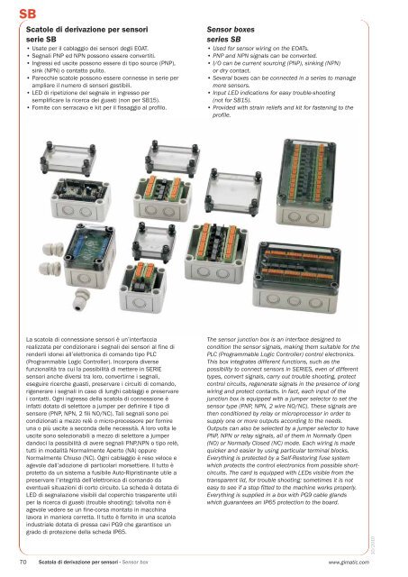
La scatola <strong>di</strong> connessione sensori è un’interfaccia<br />
realizzata per con<strong>di</strong>zionare i segnali dei sensori al fine <strong>di</strong><br />
renderli idonei all’elettronica <strong>di</strong> <strong>com</strong>ando tipo PLC<br />
(Programmable Logic Controller). Incorpora <strong>di</strong>verse<br />
funzionalità tra cui la possibilità <strong>di</strong> mettere in SERIE<br />
sensori anche <strong>di</strong>versi tra loro, convertirne i segnali,<br />
eseguire ricerche guasti, preservare i circuiti <strong>di</strong> <strong>com</strong>ando,<br />
rigenerare i segnali in caso <strong>di</strong> lunghi cablaggi e preservare<br />
i contatti. Ogni ingresso della scatola <strong>di</strong> connessione è<br />
infatti dotato <strong>di</strong> selettore a jumper per definire il tipo <strong>di</strong><br />
sensore (PNP, NPN, 2 fili NO/NC). Tali segnali sono poi<br />
con<strong>di</strong>zionati a mezzo relè o micro-processore per fornire<br />
una o più uscite a seconda delle necessità. A loro volta le<br />
uscite sono selezionabili a mezzo <strong>di</strong> selettore a jumper<br />
dandoci la possibilità <strong>di</strong> avere segnali PNP,NPN o tipo relè,<br />
tutti in modalità Normalmente Aperto (NA) oppure<br />
Normalmente Chiuso (NC). Ogni cablaggio è reso veloce e<br />
agevole dall’adozione <strong>di</strong> particolari morsettiere. Il tutto è<br />
protetto da un sistema a fusibile Auto-Ripristinante utile a<br />
preservare l’integrità dell’elettronica <strong>di</strong> <strong>com</strong>ando da<br />
eventuali situazioni <strong>di</strong> corto circuito. La scheda è dotata <strong>di</strong><br />
LED <strong>di</strong> segnalazione visibili dal coperchio trasparente utili<br />
per la ricerca <strong>di</strong> guasti (trouble shooting): talvolta non è<br />
agevole vedere se un fine-corsa montato in macchina<br />
lavora in maniera corretta. Il tutto è fornito in una scatola<br />
industriale dotata <strong>di</strong> pressa cavi PG9 che garantisce un<br />
grado <strong>di</strong> protezione della scheda IP65.<br />
The sensor junction box is an interface designed to<br />
con<strong>di</strong>tion the sensor signals, making them suitable for the<br />
PLC (Programmable Logic Controller) control electronics.<br />
This box integrates <strong>di</strong>fferent functions, such as the<br />
possibility to connect sensors in SERIES, even of <strong>di</strong>fferent<br />
types, convert signals, carry out trouble shooting, protect<br />
control circuits, regenerate signals in the presence of long<br />
wiring and protect contacts. In fact, each input of the<br />
junction box is equipped with a jumper selector to set the<br />
sensor type (PNP, NPN, 2 wire NO/NC). These signals are<br />
then con<strong>di</strong>tioned by relay or microprocessor in order to<br />
supply one or more outputs accor<strong>di</strong>ng to the needs.<br />
Outputs can also be selected by a jumper selector to have<br />
PNP, NPN or relay signals, all of them in Normally Open<br />
(NO) or Normally Closed (NC) mode. Each wiring is made<br />
quicker and easier by using particular terminal blocks.<br />
Everything is protected by a Self-Restoring fuse system<br />
which protects the control electronics from possible shortcircuits.<br />
The card is equipped with LEDs visible from the<br />
transparent lid, for trouble shooting: sometimes it is not<br />
easy to see if a stop fitted to the machine works properly.<br />
Everything is supplied in a box with PG9 cable glands<br />
which guarantees an IP65 protection to the board.<br />
10/2010<br />
70 Scatola <strong>di</strong> <strong>derivazione</strong> per sensori - <strong>Sensor</strong> box<br />
www.gimatic.<strong>com</strong>
-<br />
-<br />
-<br />
-<br />
-<br />
Scatola <strong>di</strong> <strong>com</strong>ando a microprocessore<br />
Microprocessor sensor box<br />
<strong>SB</strong>8F<br />
Funzionamento<br />
Quando si preme il pulsante AUTOSET, il microprocessore memorizza lo<br />
stato degli ingressi (AREA GRIGIA). Dopo<strong>di</strong>chè l'uscita (AREA GIALLA) verrà<br />
abilitata ogni volta che si ripresenta la medesima configurazione degli<br />
ingressi.<br />
Alimentazione<br />
24 V dc (±10%)<br />
Ingressi<br />
Fino a 8 sensori PNP, NPN o contatto pulito (NA o NC) selezionabili tramite<br />
jumper (AREA MARRONE).<br />
Uscite<br />
1 uscita PNP, NPN o contatto pulito (NA o NC) (AREA GIALLA).<br />
Functioning<br />
When the autoset button is pressed, the microprocessor memorizes the<br />
status of the inputs (GREY AREA). Afterwards the output (YELLOW AREA)<br />
will be activated every time the same input configuration happens again.<br />
Power supply<br />
24 V dc (±10%)<br />
Inputs<br />
Maximum 8 PNP, NPN or dry contact (NO or NC) sensors switched by<br />
jumpers (BROWN AREA).<br />
Outputs<br />
1 PNP, NPN or dry contact (NO or NC) (YELLOW AREA) output.<br />
Schema circuito / Layout circuit<br />
PLC<br />
EOAT<br />
C O M D R Y C O N T A C T O U T<br />
N C D R Y C O N T A C T O U T<br />
N O D R Y C O N T A C T O U T<br />
+<br />
2 4 V d c<br />
N P N O U T<br />
P N P O U T<br />
NPN<br />
SENSOR<br />
NPN<br />
SENSOR<br />
+ I N -<br />
I N 1<br />
+ I N -<br />
I N 2<br />
+ I N -<br />
I N 3<br />
+ I N -<br />
I N 4<br />
P O W E R<br />
n p n<br />
n p n<br />
n p n<br />
p n p<br />
p n p<br />
p n p<br />
n p n<br />
I N 2 I N 3 I N 4<br />
p n p<br />
I N 1<br />
S T O R E D<br />
R E A D I N G<br />
A U T O S E T<br />
n p n<br />
n p n<br />
n p n<br />
I N 5<br />
p n p<br />
p n p<br />
p n p<br />
n p n<br />
I N 8<br />
I N 7 I N 6<br />
p n p<br />
- I N + - I N + - I N + - I N +<br />
I N 8 I N 7 I N 6 I N 5<br />
REED<br />
SENSOR<br />
REED<br />
SENSOR<br />
PNP<br />
SENSOR<br />
PNP<br />
SENSOR<br />
L I N K I N<br />
L I N K O U T<br />
PNP<br />
SENSOR<br />
PNP<br />
SENSOR<br />
+<br />
2 4 V d c<br />
+<br />
2 4 V d c<br />
+<br />
+<br />
L I N K O U T<br />
L I N K I N<br />
Esempio <strong>di</strong> utilizzo<br />
Application example<br />
10/2010<br />
I N 6 I N 5<br />
+ - I N + - I N +<br />
n p n<br />
n p n<br />
I N 5<br />
p n p<br />
p n p<br />
n p n<br />
I N 7 I N 6<br />
p n p<br />
A U T O S E T<br />
S T O R E D<br />
R E A D I N G<br />
I N 2 I N 3 I N 4<br />
p n p<br />
p n p<br />
p n p<br />
n p n<br />
n p n<br />
n p n<br />
P O W E R<br />
I N -<br />
+ I N - + I N -<br />
I N 2<br />
I N 3 I N 4<br />
Alimentazione / Power supply<br />
24 V dc (±10%)<br />
Ingressi / Inputs<br />
2 NPN INPUTS (IN1/IN2)<br />
4 PNP INPUTS (IN3/IN4/IN5/IN6)<br />
2 DRY CONTACT (IN7/IN8)<br />
Uscite / Outputs<br />
1 PNP OUTPUT<br />
1 NPN OUTPUT<br />
1 DRY CONTACT NC OUTPUT<br />
1 DRY CONTACT NO OUTPUT<br />
www.gimatic.<strong>com</strong> Scatola <strong>di</strong> <strong>derivazione</strong> per sensori - <strong>Sensor</strong> box 71
<strong>SB</strong>2C - <strong>SB</strong>4C - <strong>SB</strong>6C - <strong>SB</strong>8C - <strong>SB</strong>12C<br />
Scatola <strong>di</strong> <strong>derivazione</strong> con logica a relè<br />
NA/NC<br />
Funzionamento<br />
Una volta cablati gli ingressi (AREA GRIGIA) <strong>com</strong>e specificato sulla scheda<br />
selezionare a mezzo "Jumper" il tipo <strong>di</strong> segnale d'ingresso (AREA<br />
MARRONE). Poi selezionare a mezzo "Jumper" il tipo <strong>di</strong> uscita (PNP, NPN,<br />
relay) necessaria (AREA ROSSA) e se le uscite devono essere messe in serie<br />
(NA oppure NC senza caduta <strong>di</strong> tensione) o in parallelo (AREA BLU).<br />
Terminata la selezione an<strong>di</strong>amo a cablare le uscite (AREA GIALLA).<br />
NO/NC relay logic board<br />
Functioning<br />
After the inputs have been cabled (Grey Area) as shown on the circuit board<br />
you must use “Jumper” to select the Inputs signal type (Brown Area). Then<br />
use “Jumper” to define if you want to convert the input signals in NO/NC<br />
<strong>series</strong> or parallel outputs (Blue area). Use “Jumper” also to select the<br />
Output signal (PNP; NPN; relay) (Red Area) through a relay circuit so as to<br />
avoid the voltage drop. When the selection is <strong>com</strong>pleted, the Outputs<br />
(Yellow Area) are to be cabled.<br />
Alimentazione: 24 V dc (±10%)<br />
Ingressi<br />
<strong>SB</strong>2C Fino a 2 sensori PNP, NPN o contatto pulito (NA o NC)<br />
(AREA GRIGIA) selezionabili tramite jumper (AREA MARRONE).<br />
<strong>SB</strong>4C Fino a 4 ...<br />
<strong>SB</strong>6C Fino a 6 ...<br />
<strong>SB</strong>8C Fino a 8 ...<br />
<strong>SB</strong>12C Fino a 12 ...<br />
Uscite<br />
<strong>SB</strong>2C<br />
Da 1 a 2 uscite PNP, NPN o contatto pulito (NA) (AREA GIALLA)<br />
selezionabili tramite jumper (AREA ROSSA).<br />
<strong>SB</strong>4C Da 1 a 4 uscite ...<br />
<strong>SB</strong>6C Da 1 a 6 uscite ...<br />
<strong>SB</strong>8C Da 1 a 8 uscite ...<br />
<strong>SB</strong>12C Da 1 a 12 uscite ...<br />
Power supply: 24 V dc (±10%)<br />
Inputs<br />
<strong>SB</strong>2C<br />
Maximum 2 PNP, NPN or dry contact (NO or NC) (GREY AREA)<br />
sensors switched by jumpers (BROWN AREA).<br />
<strong>SB</strong>4C Maximum 4 ...<br />
<strong>SB</strong>6C Maximum 6 ...<br />
<strong>SB</strong>8C Maximum 8 ...<br />
<strong>SB</strong>12C Maximum 12 ...<br />
Outputs<br />
<strong>SB</strong>2C 1 up to 2 PNP, NPN or dry contact (NO) outputs (YELLOW AREA)<br />
switched by jumpers (RED AREA).<br />
<strong>SB</strong>4C 1 up to 4 ...<br />
<strong>SB</strong>6C 1 up to 6 ...<br />
<strong>SB</strong>8C 1 up to 8 ...<br />
<strong>SB</strong>12C 1 up to 12 ...<br />
Schema circuito / Layout circuit<br />
10/2010<br />
72 Scatola <strong>di</strong> <strong>derivazione</strong> per sensori - <strong>Sensor</strong> box<br />
www.gimatic.<strong>com</strong>
<strong>SB</strong>2C - <strong>SB</strong>4C - <strong>SB</strong>6C - <strong>SB</strong>8C - <strong>SB</strong>12C<br />
10/2010<br />
www.gimatic.<strong>com</strong> Scatola <strong>di</strong> <strong>derivazione</strong> per sensori - <strong>Sensor</strong> box 73
<strong>SB</strong>2C - <strong>SB</strong>4C - <strong>SB</strong>6C - <strong>SB</strong>8C - <strong>SB</strong>12C<br />
Esempio <strong>di</strong> utilizzo / Application example<br />
Alimentazione / Power supply<br />
24 V dc (±10%)<br />
Ingressi / Inputs<br />
2 PNP INPUTS (IN3/IN6)<br />
2 NPN INPUTS (IN1/IN4)<br />
2 DRY CONTACT (IN2/IN5)<br />
Uscite / Outputs<br />
1 PNP OUTPUT SERIES (OUT3)<br />
1 NPN OUTPUT SERIES (OUT6)<br />
10/2010<br />
74 Scatola <strong>di</strong> <strong>derivazione</strong> per sensori - <strong>Sensor</strong> box<br />
www.gimatic.<strong>com</strong>
Scatola <strong>di</strong> cablaggio con terminali<br />
Terminal cabling box<br />
<strong>SB</strong>15<br />
Funzionamento<br />
Il circuito con terminali a vite è usato per collegare i moduli CAQC e CBQC ai<br />
sensori ed alle scatole <strong>SB</strong>2C, <strong>SB</strong>4C, <strong>SB</strong>6C, <strong>SB</strong>8C, <strong>SB</strong>12C e <strong>SB</strong>8F.<br />
Alimentazione<br />
24 V dc (±10%)<br />
Ingressi<br />
15 ingressi (<strong>di</strong>retti all’uscita)<br />
Uscite<br />
15 uscite (<strong>di</strong>rette dall’ingresso)<br />
Functioning<br />
The terminal circuit board is used to link CAQC and CBQC modules to<br />
sensors <strong>SB</strong>2C, <strong>SB</strong>4C, <strong>SB</strong>6C, <strong>SB</strong>8C, <strong>SB</strong>12C and <strong>SB</strong>8F sensor box.<br />
Power supply<br />
24 V dc (±10%)<br />
Inputs<br />
15 inputs (to outputs)<br />
Outputs<br />
15 outputs (from inputs)<br />
Schema circuito / Layout circuit<br />
10/2010<br />
www.gimatic.<strong>com</strong> Scatola <strong>di</strong> <strong>derivazione</strong> per sensori - <strong>Sensor</strong> box 75
<strong>SB</strong><br />
Dimensioni (mm) / Dimensions (mm)<br />
Viti per fissaggio al profilo estruso<br />
Screws for fastening to the extruded profile<br />
Serracavo (G) e viti per fissaggio<br />
forniti in confezione<br />
Strain reliefs (G) and fixing screws<br />
included in the packaging<br />
Serracavo<br />
Strain reliefs<br />
<strong>SB</strong>8F <strong>SB</strong>2C <strong>SB</strong>4C <strong>SB</strong>6C <strong>SB</strong>8C <strong>SB</strong>12C <strong>SB</strong>15<br />
A 57 57 57 57 57 57 57<br />
B 65 65 65 94 94 94 65<br />
C 25 25 25 25 25 25 25<br />
D 94 65 94 94 130 180 94<br />
E 79 50 79 79 115 165 79<br />
F 50 50 50 79 79 79 50<br />
G n°3 n°2 n°3 n°4 n°6 n°8 n°3<br />
Peso / Weight<br />
Prezzo / Price<br />
165 g 120 g 160 g 190 g 235 g 325 g 150 g<br />
10/2010<br />
76 Scatola <strong>di</strong> <strong>derivazione</strong> per sensori - <strong>Sensor</strong> box<br />
www.gimatic.<strong>com</strong>