Benutzerhandbuch - Online USV Systeme
Benutzerhandbuch - Online USV Systeme
Benutzerhandbuch - Online USV Systeme

Create successful ePaper yourself
Turn your PDF publications into a flip-book with our unique Google optimized e-Paper software.
<strong>Benutzerhandbuch</strong>(YUNTO P 500, YUNTO P 750, YUNTO P 1250)Deutschland Italien SchweizONLINE <strong>USV</strong>-<strong>Systeme</strong> AGDreimühlenstr.4D-80469 MünchenPhone +49 (0) 89 / 2423990-10Fax +49 (0) 89 / 2423990-20Internet: www.online-usv.de<strong>Online</strong> UPS Systems S.r.l.Via Edison 12I-20058 Villasanta (Milano)Phone +39 (0) 39 / 2 05 14 44Fax +39 (0) 39 / 2 05 14 35Internet: www.online-ups.it<strong>Online</strong> <strong>USV</strong>-<strong>Systeme</strong> AGEigenheimstraße 11CH-8304 WallisellenTel: +41 (0)44-9452829Fax: +41 (0)44-9453288Internet: http://www.onlineusv.ch/1 / 548/5/2010
1. Inhalt1. Inhalt .................................................................................................................. 22. Einleitung ........................................................................................................... 33. Sicherheitshinweise ............................................................................................ 44. Anzeige- und Bedienelemente ............................................................................ 75. Installieren und Einschalten ................................................................................ 96. Fehler beheben ................................................................................................. 107. Wartung ............................................................................................................ 127.1 Betrieb ...................................................................................................... 127.2 Lagerung ................................................................................................... 128. Technische Daten ............................................................................................. 138.1 Elektrische Spezifikation .......................................................................... 138.2 Typische Überbrückungszeit (Batteriebetrieb) ......................................... 148.3 Maße und Gewichte .................................................................................. 148.4 Betriebsumgebung .................................................................................... 148.5 Schnittstellenanschluß (nur YUNTO P-Serie) .......................................... 149. Anhang ............................................................................................................. 172 / 548/5/2010
2. EinleitungDie ONLINE <strong>USV</strong> YUNTO P-Serie ist eine neu entwickelte Line-Interactive-<strong>USV</strong>mit simulierter Sinuswelle zur unterbrechungsfreien Stromversorgung. Die Line-Interactive Technologie basiert auf der permanenten Analyse der Eingangsspannung.Weicht die Spannung von den Idealwerten ab oder fällt sie vollkommen aus,übernimmt ein Hochleistungswechselrichter innerhalb von 2 Millisekunden die Versorgungder Verbraucher. Die eingebauten Batterien sind wartungsfrei. Bei Stromausfällenwerden die angeschlossenen Rechner für circa 10 Minuten mit einer simuliertenSinuswelle versorgt. Optimal abgestimmte Filter schützen vor Spannungsspitzenund verhindern Hardwareschäden.3 / 548/5/2010
3. SicherheitshinweiseVOR INSTALLATION UND INBETRIEBNAHME DAS BENUTZERHAND-BUCH UND DIE SICHERHEITSHINWEISE AUFMERKSAM LESEN UNDBEACHTEN!Transport<strong>USV</strong>-Anlage nur in der Originalverpackung transportieren (Schutz gegen Stoßund Schlag).AufstellungWird die <strong>USV</strong>-Anlage aus kalter Umgebung in den Arbeitsraum gebracht, kannBetauung auftreten. Vor Inbetriebnahme muß die <strong>USV</strong>-Anlage absolut trockensein. Deshalb eine Akklimatisationszeit von mindestens zwei Stunden abwarten.<strong>USV</strong>-Anlage nicht in der Nähe von Wasser oder in feuchter Umgebung aufstellen.<strong>USV</strong>-Anlage nicht in direktem Sonnenlicht oder in der Nähe von Wärmequellenaufstellen.Lüftungsöffnungen im Gehäuse der <strong>USV</strong>-Anlage nicht blockieren.Anschluß<strong>USV</strong>-Anlage nur an einer geerdeten Schutzkontaktsteckdose anschließen.Nicht versuchen, die <strong>USV</strong>-Anlage an eine andere Steckdose als eine Schutzkontaktsteckdoseanzuschließen.Steckdose der Hausinstallation (Schutzkontaktsteckdose) muß leicht zugänglichsein und sich in der Nähe der <strong>USV</strong>-Anlage befinden.Zum Anschluß der <strong>USV</strong>-Anlage an die Steckdose der Hausinstallation (Schutzkontaktsteckdose)nur ein VDE-geprüftes und CE-gekennzeichnetes Netzkabel(z.B. das ihres Computers) verwenden.Zum Anschluß der Verbraucher an die <strong>USV</strong>-Anlage nur VDE-geprüfte und CEgekennzeichneteStromkabel verwenden.4 / 548/5/2010
Keine Haushaltsgeräte, wie beispielsweise Haartrockner, in <strong>USV</strong>-Ausgangssteckdosen anschließen.Keine Geräte an die <strong>USV</strong>-Ausgangssteckdosen anschließen, die die <strong>USV</strong>-Anlage überlasten (z. B. Laserdrucker).Leitungen so verlegen, daß niemand darauf treten oder darüber stolpern kann.BetriebNetzkabel während des Betriebs nicht von der <strong>USV</strong>-Anlage oder der Steckdoseder Hausinstallation (Schutzkontaktsteckdose) abziehen, da sonst die Schutzerdungder <strong>USV</strong>-Anlage und aller angeschlossenen Verbraucher aufgehoben wird.Die <strong>USV</strong>-Anlage verfügt über eine eigene, interne Stromquelle (Batterien). Die<strong>USV</strong>-Ausgangssteckdosen können stromführend sein, selbst wenn die <strong>USV</strong>-Anlage nicht an die Steckdose der Hausinstallation angeschlossen ist.Zum völligen Abschalten der <strong>USV</strong>-Anlage zunächst den Ein-/Aus-Schalter inAUS-Position (Druckschalter: eingerastet = EIN, entspannt= AUS) bringen unddann das Netzkabel herausziehen.Darauf achten, daß keine Flüssigkeit oder sonstige Fremdkörper in die <strong>USV</strong>-Anlage gelangen.Wartung, Service, StörungenDie <strong>USV</strong>-Anlage enthält Spannungen, die gefährlich sind. Reparaturen sindgrundsätzlich nur von qualifiziertem Wartungspersonal durchzuführen.Achtung - Gefahr von Stromschlägen. Selbst nach Trennung vom Stromversorgungsnetz(Steckdose der Hausinstallation) bleiben Bauteile innerhalb der <strong>USV</strong>-Anlage an die Batterien angeschlossen und befinden sich unter gefährlichemSpannungspotential. Vor der Durchführung von Service- und WartungsarbeitenBatterieversorgungskreis trennen und Spannungsfreiheit prüfen.Das Auswechseln der Batterien ist durch Personal mit Sachkenntnis über Batterienund Kenntnis über die geforderten Vorsichtsregeln durchzuführen und zuüberwachen. Unbefugte Personen sind von den Batterien fernzuhalten.Achtung - Gefahr von Stromschlägen. Der Batteriestromkreis ist von der Eingangsspannungnicht getrennt. Zwischen den Batterieanschlüssen und der Erdekönnen gefährliche Spannungen auftreten. Vor dem Berühren prüfen, ob Spannungvorhanden ist!5 / 548/5/2010
Batterien können Stromschlag verursachen und weisen hohen Kurzschlußstromauf. Bei Arbeiten mit Batterien sind u. a. folgende Vorsichtsmaßregeln zu beachten:- Armbanduhren, Ringe oder andere Metallgegenstände entfernen.- nur Werkzeuge mit isolierten Griffen verwenden.Beim Austauschen der Batterien dieselbe Anzahl und denselben Batterietypverwenden.Batterien nicht ins Feuer werfen, die Batterien könnten explodieren.Batterien nicht öffnen oder zerstören. Freigesetztes Elektrolyt ist schädlich fürHaut und Augen. Es kann giftig sein.Zum Schutz vor einem Brand darf die Sicherung nur durch einen gleichen Typmit gleichem Nennwert ersetzt werden.<strong>USV</strong>-Anlage nicht auseinanderbauen.6 / 548/5/2010
4. Anzeige- und BedienelementeSchalter/TastenEin-/Aus-Schalter(Gerätevorderseite)Funktion<strong>USV</strong>-Anlage ein- und ausschalten:<strong>USV</strong>-Anlage ist eingeschaltet, wenn Druckschalter eingerastetist.<strong>USV</strong>-Anlage ist ausgeschaltet, wenn Druckschalter entspanntist.Reset-Taste(Geräterückseite,nurYUNTO P500,YUNTO P750undYUNTO P1250)1. Abschalten des akustischen Alarms bei Batteriebetrieb(wenn die Batterien soweit entladen sind, daß die verbleibendeÜberbrückungszeit weniger als 2 Minuten beträgt,kann der akustische Alarm bei Batteriebetrieb nicht mehrabgestellt werden).2. Starten der <strong>USV</strong>-Anlage aus den Batterien (nur YUNTOP 500, YUNTO P 750, YUNTO P 1250) falls das Stromversorgungsnetznicht vorhanden ist. In diesem Fall ist nachEinschalten der <strong>USV</strong>-Anlage mit dem Ein-/Aus-Schalternoch die Reset-Taste zu drücken. Schalten Sie hierbei die anden Ausgang der <strong>USV</strong>-Anlage angeschlossenen Verbrauchererst ca. 20 Sekunden nach dem Start der <strong>USV</strong>-Anlage ein.7 / 548/5/2010
DIP Schalter(Geräterückseite)Einstellungen an diesen Schaltern dürfen nur von Fachpersonalvorgenommen werden!Schalter 1:Reduzieren der unteren Schwelle der Eingangsspannung, beider auf Batteriebetrieb geschaltet wird, um 10 V (von 196 Vauf 186 V) in ON-Position.Schalter 2:Anheben der Ausgangsspannung um 5 % in ON-Position.Schalter 3:Absenken der Ausgangsspannung um 5 % in ON-Position.Betriebszustandsanzeige(Leuchtdiode /LED)Achtung!In der Regel sollten Schalter 1 und 2 in Stellung “OFF” undSchalter 3 in Stellung “ON” sein.Zeigt den Status der <strong>USV</strong>-Anlage an:Betrieb über Netz (LED leuchtet grün)Betrieb über Batterien oder <strong>USV</strong>-Fehler (LED leuchtet rot)Betriebszustandsanzeige(Flüssigkristallanzeige/ LCD)Folgende Informationen werden angezeigt:Betrieb über Netz (NORMAL)Betrieb über Netz und Batterieladung (NORMALCHARG’G blinkt)Betrieb über Batterien (BATTERY)Betrieb über Batterien und Überbrückungszeit < 2 Minuten(BATTERY 1. low stage)8 / 548/5/2010
5. Installieren und Einschalten1) Überprüfen Sie den Verpackungskarton und den Inhalt auf Schäden. Sollten SieSchäden feststellen, informieren Sie sofort den Spediteur. Bewahren Sie dieVerpackung für künftige Verwendungszwecke auf.2) Schließen Sie die <strong>USV</strong>-Anlage über ein VDE-geprüftes und CEgekennzeichnetesNetzkabel (z.B. das Ihres Computers) an eine Schutzkontaktsteckdoseder Hausinstallation an. Bei besonderen Steckdosentypen wenden Siesich bitte an Ihren Fachhändler.3) Laden Sie die Batterien der <strong>USV</strong>-Anlage vollständig auf, indem Sie die <strong>USV</strong>-Anlage für 4 Stunden am Versorgungsnetz angeschlossen lassen. Sie können die<strong>USV</strong>-Anlage auch unmittelbar ohne Laden einsetzen, doch kann dann die Überbrückungszeitkürzer als der angegebene Nennwert sein.Hinweis:Die <strong>USV</strong>-Anlage lädt die Batterien automatisch auf, sobald sie an eine Steckdoseder Hausinstallation angeschlossen ist und der Ein-/Aus-Schalter in EIN-Position (Druckschalter eingerastet) gebracht wird.4) Schließen Sie Ihren Computer über das mitgelieferte Stromkabel an die <strong>USV</strong>-Ausgangssteckdosen an.Achtung!Schließen Sie keine Geräte an die <strong>USV</strong>-Ausgangssteckdosen an, die die<strong>USV</strong>-Anlage überlasten (z. B. Laserdrucker). Schließen Sie keine Haushaltsgerätean die <strong>USV</strong>-Anlage an.5) Bringen Sie den Ein-/Aus-Schalter an der Gerätevorderseite in Stellung EIN,indem Sie ihn eindrücken.6) Testen Sie die Funktion der <strong>USV</strong>-Anlage, indem Sie den Eingang der <strong>USV</strong>-Anlage durch Auslösen der Sicherung der Hausinstallation spannungsfrei schalten.Achtung!An den Ausgangssteckdosen der <strong>USV</strong>-Anlage kann eine Spannung anstehen,auch wenn das Versorgungsnetz abgeschaltet oder das Netzkabel abgezogenist.9 / 548/5/2010
6. Fehler behebenWenn die <strong>USV</strong>-Anlage nicht einwandfrei arbeitet, versuchen Sie bitte anhand folgenderTabelle das Problem zu lösen.Problem Mögliche Ursache AbhilfeEin-/Aus-Schalter in StellungAUS (entspannt)Eingangssicherung der<strong>USV</strong>-Anlage defekt / Sicherungsautomathat ausgelöst(bei YUNTOP 1250)keine Ausgangsspannungkeine AnzeigeEingangsspannung fehltEin-/Aus-Schalter in StellungAUS (entspannt)Eingangssicherung der<strong>USV</strong>-Anlage defekt / Sicherungsautomathat ausgelöst(bei YUNTOP 1250)Eingangsspannung fehltEin-/Aus-Schalter in StellungEIN (eingerastet) bringenLast überprüfen, bei ÜberlastAnzahl der Verbraucher reduzieren,dann Eingangssicherungüberprüfen und gegebenenfallsaustauschen / Sicherungsautomatdurch Drücken einschaltenSteckdose der Hausinstallationüberprüfen, EingangskabelüberprüfenEin-/Aus-Schalter in StellungEIN (eingerastet) bringenLast überprüfen, bei ÜberlastAnzahl der Verbraucher reduzieren,dann Eingangssicherungüberprüfen und gegebenenfallsaustauschen/ Sicherungsautomatdurch Drücken einschaltenSteckdose der Hausinstallationüberprüfen, Eingangskabelüberprüfen10 / 548/5/2010
<strong>USV</strong>-Anlage gibtakustischenAlarm im Sekundentakt(nur YUNTO P1250)Überbrückungszeitkürzer alsNennwertÜberlastung der <strong>USV</strong>-AnlageBatterien nicht voll geladen/ Batterien defektAnzahl der Verbraucher am<strong>USV</strong>-Ausgang reduzierenBatterien mindestens 4 Stundenladen. Kapazität kontrollieren.Falls Problem nicht behoben,bitte an Ihren Fachhändler wenden.Bei Benachrichtigung der Serviceabteilung bitte folgende Informationen bereithalten:1. Modellnummer, Seriennummer2. Datum, an dem das Problem auftrat3. Ausführliche Beschreibung des Problems11 / 548/5/2010
7. Wartung7.1 BetriebDie <strong>USV</strong>-Anlage bedarf keiner Wartung durch den Benutzer.Wenn die Batteriegebrauchsdauer (3 - 5 Jahre bei 25°C Umgebungstemperatur)überschritten ist, müssen die Batterien ausgetauscht werden. Wenden Sie sich indiesem Fall an Ihren Fachhändler.7.2 LagerungBei Lagerung in gemäßigten Klimazonen sollten die Batterien alle drei Monate für 8Stunden geladen werden (siehe Kapitel “Installieren und einschalten”). An Ortenmit höheren Temperaturen sollten Sie die Ladeintervalle auf zwei Monate verkürzen.12 / 548/5/2010
8. Technische Daten8.1 Elektrische SpezifikationModell YUNTO P 500 YUNTO P 750 YUNTO P 1250EINGANGSpannung230VACFrequenz50 HzStromstärke (ohne 2,2 A 3,3 A 5,4 ABatterieladung)AUSGANGNennleistung500 VA300 W750 VA450 W1250 VA750 WSpannung 230 VAC ± 5%Frequenz50 Hz ±0,5 HzWellenformSimulierte SinuswelleBATTERIENAnzahl, Typ 1 St. 12V 7Ah 2 St. 12V 4Ah 2 St. 12V 7,2AhDie Geräte haben CE-Kennzeichen und erfüllen folgende Normen (GrenzwertklasseB):DIN EN 60950 Klassifikation VDE 0805:1993,DIN EN 60950:1992 + A1:1993,IEC 950:1991 + A1:1992,DIN VDE 0558 Teil 5/09.88,EN 55022,EN 60555-2,IEC 801-2,IEC 801-3,IEC 801-4,IEC 801-5 Level 1.13 / 548/5/2010
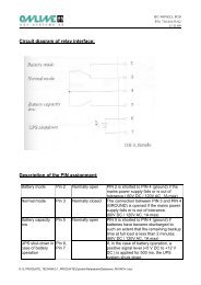
8.2 Typische Überbrückungszeit (Batteriebetrieb)Modelltypisch bei 25 °C und50 % LastTypisch bei 25 °C und100 % LastYUNTO P 500 10 5YUNTO P 750 10 5YUNTO P 1250 20 88.3 Maße und GewichteModellAbmessungenB x H x T (mm)Gewicht(kg)YUNTO P 500 95 x 160 x 350 9YUNTO P 750 95 x 160 x 350 10,5YUNTO P 1250 150 x 230 x 430 208.4 BetriebsumgebungTemperatur: 10 °C bis 40 °CRelative Luftfeuchte: 0 bis 95 % nicht kondensierend8.5 Schnittstellenanschluß (nur YUNTO P-Serie)Über den Schnittstellenanschluß (Relaiskontakte) an der Rückseite der <strong>USV</strong>-Anlagekann ein Computer angeschlossen werden. Dieser Anschluß ermöglichtdie Überwachung der <strong>USV</strong>-Anlage,die Überwachung des Stromversorgungsnetzes,die Sicherung von Daten sowie die Abschaltung des Computers unddie Abschaltung der <strong>USV</strong>-Anlage.14 / 548/5/2010
Zur Realisierung dieser Funkionen existieren verschiedene Softwarelösungen. Detailshierzu erfahren Sie von Ihrem Fachhändler.Schnittstellenanschluß:Anmerkung:PIN 5 darf nur an die Masse angeschlossen werden!15 / 548/5/2010
Beschreibung der PIN-Belegung:Pin-Nr.Batteriebetrieb 1 normalerweiseoffenPIN 1 wird gegen PIN 5 (Masse)kurzgeschlossen, falls Stromversorgungsnetzausfällt oder außerhalbder zulässigen Toleranzenist.Masseanschluß und 5gemeinsame Wurzelder Kontakte an PIN1, 8 und 9<strong>USV</strong>-Abschaltung 7 Wenn ein positiver Signalpegel(+5 V bis + 12 VDC) anliegt,schaltet sich die <strong>USV</strong>-Anlage ab(PIN 5 ist die Masse).Batteriekapazitätniedrig8 normalerweiseoffenBatteriebetrieb 9 normalerweisegeschlossenPIN 8 wird gegen PIN 5 (Masse)kurzgeschlossen, wenn Batteriensoweit entladen sind, daß verbleibendeÜberbrückungszeit wenigerals 2 Minuten beträgt.Die Verbindung zwischen PIN 9und PIN 5 (Masse) wird getrennt,falls Stromversorgungsnetz ausfälltoder außerhalb der zulässigenToleranzen ist.16 / 548/5/2010
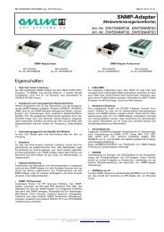
9. AnhangVorder- und Rückansicht YUNTO P 500 / 75017 / 548/5/2010
Vorder- und Rückansicht YUNTO P 125018 / 548/5/2010
Manuale d’uso(YUNTO P 500, YUNTO P 750, YUNTO P 1250)Germania Italia SvizzeraONLINE <strong>USV</strong>-<strong>Systeme</strong> AGDreimühlenstr.4D-80469 MünchenPhone +49 (0) 89 / 2423990-10Fax +49 (0) 89 / 2423990-20Internet: www.online-usv.de<strong>Online</strong> UPS Systems S.r.l.Via Edison 12I-20058 Villasanta (Milano)Phone +39 (0) 39 / 2 05 14 44Fax +39 (0) 39 / 2 05 14 35Internet: www.online-ups.itONLINE <strong>USV</strong>-<strong>Systeme</strong> AGIndustriestrasse 26CH-8604 VolketswilPhone +41 (0) 1 / 9 45 28 29Fax +41 (0) 1 / 9 45 32 88Internet: www.online-usv.ch19 / 548/5/2010
1. Indice1. Indice ................................................................................................................ 202. Introduzione ..................................................................................................... 213. Norme di sicurezza ........................................................................................... 224. Comandi e segnalazioni .................................................................................... 255. Installazione e messa in funzione ..................................................................... 276. Eliminazione dei problemi................................................................................ 287. Manutenzione ................................................................................................... 307.1 Funzionamento ......................................................................................... 307.2 Magazzinaggio ......................................................................................... 308. Dati tecnici ....................................................................................................... 318.1 Specifiche elettriche ................................................................................. 318.2 Autonomie tipiche (funzionamento in modo batteria) .............................. 328.3 Dimensioni e peso .................................................................................... 328.4 Condizioni ambientali di funzionamento .................................................. 328.5 Porta di comunicazione(YUNTO P 500, YUNTO P 750, YUNTO P 1250) .................................. 329. Appendice......................................................................................................... 3520 / 548/5/2010
2. IntroduzioneGli ONLINE UPS YUNTO Serie P sono i più avanzati gruppi di continuità a tecnologiaLine-Interactive con forma d’onda in uscita di sinuoide simulata. La tecnologiaLine-Interactive si basa su una costante analisi della tensione elettrica di rete. Incaso di scostamento della tensione dal valore ideale, nel giro di 2 ms, le utenze vengonoalimentate direttamente dall’inverter dell’UPS. Le batterie interne non richiedonoalcuna manutenzione e consentono un’autonomia di lavoro di ca. 10 min.Gli opportuni filtri presenti proteggono le utenze da numerosi disturbi elettrici comeradiofrequenze, interferenze elettromagnetiche, picchi etc.21 / 548/5/2010
3. Norme di sicurezzaLEGGERE ATTENTAMENTE E SEGUIRE LE ISTRUZIONI E LE NORMEDI SICUREZZA DEL PRESENTE MANUALE PRIMADELL’INSTALLAZIONE E DELLA MESSA IN FUNZIONE DELL’ UPS !TrasportoEffettuate il trasporto del gruppo di continuità solo all’interno dell’imballo originale(protezione contro urti e scossoni).CollocazioneQualora l’UPS provenisse da un ambiente molto freddo, potrebbe presentare,una volta introdotto in locali a temperatura ambiente, tracce di umidità. Primadella messa in funzione, il gruppo di continuità deve essere perfettamente asciutto.Attendere quindi un periodo di acclimatamento di almeno due ore.Non installare l’UPS nelle vicinanze di acqua o in ambienti a rischio di incendio.Non installare l’UPS a diretto contatto con la luce solare o nelle vicinanze dialtre fonti di caloreNon ostruire le prese d’aria presenti sull’involucro del gruppo di continuità.CollegamentoCollegare l’UPS esclusivamente ad una presa tripolare. Non cercare di collegarel’UPS a qualunque altro tipo di presa.La presa tripolare per il collegamento deve essere facilmente accessibile e nellevicinanze del gruppo di continuità.Per tutti i collegamenti utilizzare esclusivamente cavi certificati VDE e marchiatiCE.Non collegate alcun elettrodomestico (ad es. asciucapelli) all’ UPS.Non collegate alcuna apparecchiatura in grado di portare in sovraccarico l’UPS(ad es. stampante laser).22 / 548/5/2010
Collocate i cavi in maniera che nessuno possa schiaccarli o inciampare.FunzionamentoNon sconnettete il cavo di alimentazione dalla presa di rete o dall’UPS durante ilfunzionamento. In tal caso verrebbe a mancare istantaneamente la protezione(messa a terra) per il gruppo di continuità e per tutte le utenze ad esso collegate.L’UPS dispone di una fonte interna di energia (Batterie). E’ quindi presente tensioneelettrica all’uscita dell’ UPS anche se non collegato alla rete elettrica.Per una totale disconnessione del gruppo di continuità dall’alimentazione di rete,verificate innanzitutto che l’interruttore On/Off sia nella posizione Off (premendoloe rilasciandolo), dopodichè scollegate il cavo di alimentazione.Fate in modo che nessun liquido o corpo solido estraneo venga in contatto conl’UPS.Manutenzione, Assistenza, GuastiAll’interno del gruppo di continuità sono presenti pericolose tensioni elettriche.Per questa ragione eventuali riparazioni vanno effettuate solo da personale specializzato.Attenzione - Pericolo di scosse elettriche. Anche dopo la sconnessione dalla reteelettrica, vi sono componenti interni del gruppo di continuità collegati alle batteriee quindi in grado di generare pericolose tensioni elettriche. Prima di eventualiriparazioni o manutenzioni dell’ UPS, scollegare le batterie staccandol’apposito connettore e verificare, tramite tester, l’assoluta assenza di tensionielettriche.Effettuate la sostituzione delle batterie solo se già esperti in questa operazione ese a conoscenza delle esatte procedure di sicurezza richieste. Il personale inespertova tenuto lontano dalle batterie.Attenzione - Pericolo di scosse elettriche. Le batterie non sono sconnesse dallatensione in ingresso. Tra i collegamenti delle batterie e la terra possono generarsipericolose tensioni elettriche. Prima di toccare le batterie verificare la presenzadi tensione !23 / 548/5/2010
Le batterie possono causare forti scosse elettriche e corto circuito. Nel caso dimanutenzione delle batterie, seguire attentamente le seguenti norme di sicurezza:- Non indossare orologio, anelli ed eventuali ulteriori oggetti metallici.- Utilizzare solo attrezzi con impugnatura isolata.Sostituire le batterie solo con lo stesso numero e tipo di batterie.Non gettare le batterie nel fuoco, possono scoppiare.Non aprite o danneggiate le batterie, gli elettroliti presenti all’interno sono velenosie pericolosi per pelle e occhi.Effettuate l’eventuale sostituzione del fusibile di protezione con uno dello stessotipo e valore nominale.Non smontate il gruppo di continuità.24 / 548/5/2010
4. Comandi e segnalazioniInterruttore/TastoInterruttoreOn/Off(Fronte UPS)Tasto Reset-(Retro UPS,soloYUNTO P 500,YUNTO P 750eYUNTO P 1250)DIP-switch(Retro UPS)Accende e spegne l’UPS:FunzioneSchiacciando il tasto si accende l’UPS,Premendo nuovamente, il tasto rilasciandosi spegne l’UPS.1. Spegne l’allarme acustico in caso di funzionamento in modobatteria (quando la carica restante delle batterie consenteun’autonomia inferiore ai 2 minuti, questa funzione di spegnimentodell’allarme acustico può venire a mancare).2. Avvia l’UPS da modo batteria (solo YUNTO P 500, YUN-TO P 750, YUNTO P 1250), qualora non presente la tensionedi rete. In questo caso, schiacciare il tasto On/Off in posizioneON, e premere il tasto reset per ca. 3 sec. Dopo ca. 20sec. dall’accensione dell’UPS, le utenze collegate vengonoalimentate.L’utilizzo di questo switch va effettuato solo da personalespecializzato!DIP-switch 1:Nella posizione ON, riduce la soglia di intervento del modobatterie, per bassa tensione di ingresso, di 10V da 196V a 186V.DIP-switch 2:In posizione ON, aumenta il valore della tensione in uscita del5%.DIP-switch 3:In posizione ON, riduce il valore della tensione in uscita del 5%.Attenzione!Di norma, Switch 1 e 2 sono in posizione “OFF” e Switch 3 èin posizione “ON”.25 / 548/5/2010
LED di statoDisplay di stato acristalli liquidi(LCD)Segnala lo stato dell’UPS:Funzionamento normale (LED illuminato in verde)Funzionamento in batteria o guasto-UPS (LED illuminato inrosso)Vengono visualizzate le seguenti indicazioni di stato:Funzionamento normale (NORMAL)Funzionamento normale e carico batterie (NORMAL piùCHARG’G lampeggiante)Funzionamento in modo batteria (BATTERY)Funzionamento in modo batteria e autonomia < 2 minuti(BATTERY 1. low stage)26 / 548/5/2010
5. Installazione e messa in funzione1) Verificate le condizioni dell’imballo ed in caso di presenza di danneggiamentiavvertite immediatamente lo spedizioniere e ritirate la merce “con riserva”.Conservare l’imballo per eventuali utilizzi futuri.2) Collegate l’UPS tramite cavo certificato VDE e marchiato CE ad una presa tripolare.In presenza di particolari tipi di presa, rivolgetevi al Vs. fornitore.3) Caricate al massino le batterie dell’UPS. A questo proposito, lasciate collegatol’UPS alla rete elettrica per 4 ore. Potete utilizzare l’UPS senza una preventivacarica totale delle batterie, in questo caso però, il periodo di autonomia in casodi blackout può risultare più breve di quello indicato.Notainformativa:L’UPS inizia a caricare automaticamente le batterie non appena è collegatoall’alimentazione di rete e l’interruttore On-/Off è in posizione ON (schiacciandol’interruttore).4) Collegate il Vs. computer all’uscita dell’UPS tramite il cavo in dotazione.Attenzione!Non collegate alcuna apparecchiatura in grado di portare in sovraccaricol’UPS (ad es. stampante laser). Non collegate alcun elettrodomestico all’UPS.5) Schiacciate l’interruttore On/Off, sul fronte UPS, portandolo in posizione ON.6) Testate il funzionamento dell’UPS, premendo il tasto “Test” o scollegandol’alimentazione elettrica di rete tramite l’apposito interruttore generale.Attenzione!All’uscita dell’UPS può essere presente tensione elettrica anche in caso diassenza della tensione di rete e di scollegamento del cavo di alimentazione.27 / 548/5/2010
6. Eliminazione dei problemiSe il funzionamento dell’UPS presenta delle anomalie, provate ad eliminarle secondole istruzioni della seguente tabella:Problema Causa probabile RimedioNessuna tensionein uscita UPSNessuna segnalazioneAllarme acusticodell’UPS (soloYUNTO P 1250)Interruttore On/Off in posizioneOFF (rilasciato)Danno alla protezione diingresso dell’UPS / disattivazionedella protezioneautomatica (per YUNTO P1250)Assenza di tensioneall’ingresso UPSInterruttore On/Off in posizioneOFF (rilasciato)Danno alla protezione diingresso dell’UPS / disattivazionedella protezioneautomatica (per YUNTO P1250)Assenza di tensioneall’ingresso UPSSovraccarico dell’UPSSchiacciare l’interruttore On/Offportandolo in posizione ONVerificare il carico collegatoall’UPS, in caso di sovraccaricoridurre il numero di utenze collegate,controllare la protezione diingresso dell’UPS ed eventualmentesostituirla / reinserire laprotezione automatica (YUNTO P1250)Controllare presa e cavo di alimentazioneSchiacciare l’interruttore On/Offportandolo in posizione ONVerificare il carico collegatoall’UPS, in caso di sovraccaricoridurre il numero di utenze collegate,controllare la protezione diingresso dell’UPS ed eventualmentesostituirla / reinserire laprotezione automatica (YUNTO P1250)Controllare presa e cavo di alimentazioneRiducete il numero di utenze collegateall’UPS28 / 548/5/2010
Periodo di autonomiapiù brevedel valore previstoBatterie non a pieno carico/ Batterie difettoseRicaricate le batterie per almeno 4ore e testate il tempo di autonomia.Se il problema permane, rivolgetevial Vs. fornitore.Per una tempestiva assistenza comunicate le seguenti informazioni:1. Modello e numero di matricola2. Data di acquisto ed installazione3. Dettagliata descrizione del problema29 / 548/5/2010
7. Manutenzione7.1 FunzionamentoL’UPS non richiede manutenzione da parte dell’utilizzatore.Passato un certo periodo (3-5 anni a 25°C) occorre sostituire le batterie dell’UPS. Inquesto caso rivolgetevi al Vs. fornitore.7.2 MagazzinaggioIn caso di magazzinaggio a temperature normali, caricate le batterie per 1-2 ore ognitre mesi (consultate il capitolo “Installazione e messa in funzione”). Per stoccaggi atemperature superiori alla media occorre effettuare tale operazione ogni 2 mesi.30 / 548/5/2010
8. Dati tecnici8.1 Specifiche elettricheModello YUNTO P 500 YUNTO P 750 YUNTO P 1250ENTRATATensione230 V ACFrequenza50 HzAssorbimento 2,2 A 3,3 A 5,4 A(senza Caricabatterie)USCITAPotenza nominale500 VA300 W750 VA450 W1250 VA750 WTensione 230 VAC 5 %Frequenza 50 Hz 0,5 Hz (autoselezionante)Forma d’ondasinusoide simulataBATTERIENumero e tipo 1 x 12V7Ah 2 x 12V4Ah 2 x 12V 8AhQuesti UPS sono certificati CE e sono conformi alle seguenti norme (Classe B):DIN EN 60950 classificazione VDE 0805:1993,DIN EN 60950:1992 + A1:1993,IEC 950:1991 + A1:1992,DIN VDE 0558 part 5/09.88,EN 55022,EN 60555-2,IEC 801-2,IEC 801-3,IEC 801-4,IEC 801-5 Level 1.31 / 548/5/2010
8.2 Autonomie tipiche (funzionamento in modo batteria)Modello autonomia tipica a 25 °C ecarico 50 % (min)autonomia tipica a 25 °C ecarico 100 % (min)YUNTO P 500 10 5YUNTO P 750 10 5YUNTO P 1250 20 88.3 Dimensioni e pesoModelloDimensioniL x A x P (mm)Peso(kg)YUNTO P 500 95 x 160 x 350 9,0YUNTO P 750 95 x 160 x 350 10,5YUNTO P 1250 150 x 230 x 430 20,08.4 Condizioni ambientali di funzionamentoTemperatura: da 10 °C a 40 °CUmidità relativa: da 0 a 95 % senza condensa8.5 Porta di comunicazione(YUNTO P 500, YUNTO P 750, YUNTO P 1250)E’ possibile collegare i computer alla porta di comunicazione (porta relais) posta sulretro dell’UPS.Questo collegamento consente:la sorveglianza del gruppo di continuità,32 / 548/5/2010
la sorveglianza dell’alimentazione elettrica di rete,la sicurezza dei dati,lo spegnimento dei computer elo spegnimento dell’UPS.Per la realizzazione di queste funzioni esistono diverse soluzioni-software. Per ulterioridettagli contattate il Vs. fornitore.Schema porta relais di comunicazione:Nota:Il PIN 5 deve essere connesso a massa (ground) !33 / 548/5/2010
Descrizione della funzione dei PIN:Funzionamento in modobatteriePin-Nr.1 normalmenteapertoPIN 1 si cortocircuita con PIN 5(Massa), in caso di blackout o ditensione di rete in ingresso al difuori del range permesso.Collegamento di massa 5e punto comune dicollegamento per PIN1, 8 e 9Spegnimento UPS 7 Quando arriva un segnale positivo(da +5 V a + 12 VDC),l’UPS si spegne (PIN 5 è lamassa).Fine autonomia 8 normalmenteapertoFunzionamento in modobatterie9 normalmentechiusoPIN 8 viene cortocircuitato conPIN 5 (Massa) quando le batteriesono così scariche da consentire,in condizioni di carico100% collegato all’UPS,un’autonomia inferiore ai 2 minuti.Il collegamento tra PIN 9 e PIN5 (Massa) viene interrotto incaso di blackout o di tensione direte in ingresso al di fuori delrange permesso.34 / 548/5/2010
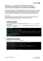
9. AppendiceFronte e Retro YUNTO P 500 / 75035 / 548/5/2010
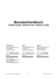
Fronte e Retro YUNTO P 125036 / 548/5/2010
User Manual(YUNTO P 500, YUNTO P 750, YUNTO P 1250)Germany Italy SwitzerlandONLINE <strong>USV</strong>-<strong>Systeme</strong> AGDreimühlenstr.4D-80469 MünchenPhone +49 (0) 89 / 2423990-10Fax +49 (0) 89 / 2423990-20Internet: www.online-usv.de<strong>Online</strong> UPS Systems S.r.l.Via Edison 12I-20058 Villasanta (Milano)Phone +39 (0) 39 / 2 05 14 44Fax +39 (0) 39 / 2 05 14 35Internet: www.online-ups.itONLINE <strong>USV</strong>-<strong>Systeme</strong> AGIndustriestrasse 26CH-8604 VolketswilPhone +41 (0) 1 / 9 45 28 29Fax +41 (0) 1 / 9 45 32 88Internet: www.online-usv.ch37 / 548/5/2010
1. Contents1. Contents ............................................................................................................ 382. Introduction ...................................................................................................... 393. Safety Instructions ............................................................................................ 404. Indicators and Operating Controls .................................................................... 435. Installation and Start Up ................................................................................... 456. Troubleshooting ............................................................................................... 467. Maintenance ..................................................................................................... 487.1 Operation .................................................................................................. 487.2 Storage ...................................................................................................... 488. Technical Data .................................................................................................. 498.1 Electrical specifications ............................................................................ 498.2 Typical stored energy time (Battery mode) .............................................. 508.3 Dimensions and weights ........................................................................... 508.4 Operating environment ............................................................................. 508.5 Port connector (YUNTO P 500, YUNTO P 750, YUNTO P 1250) ....... 509. Annex ............................................................................................................... 5338 / 548/5/2010
2. IntroductionThe <strong>Online</strong> UPS YUNTO P-Series is a newly developed Line-Interactive systemwith simulated sine wave for uninterruptible power supply. Line Interactive technologyis based on permanent analysis of the input voltage. If the voltage deviatesfrom the ideal values or if it fails entirely, a high-performance inverter assumes thetask of powering the loads within a period of 2 milliseconds. The incorporated batteriesrequire no maintenance. In the event of power failures, the connected computersare powered with a simulated sine wave for approx. 10 minutes. Optimallymatched filters protect against break-down and prevent hardware damage.39 / 548/5/2010
3. Safety InstructionsPLEASE READ THROUGH AND FOLLOW THE USER MANUAL ANDTHE SAFETY INSTRUCTIONS BEFORE INSTALLING THE UNIT ANDSTARTING IT UP!TransportPlease transport the UPS system only in the original packaging (to protectagainst shock and impact).Set-upCondensation may occur if the UPS system is moved directly from a cold to awarm environment. The UPS system must be absolutely dry before being installed.Please allow an acclimatisation time of at least two hours.Do not install the UPS system near water or in damp environments.Do not install the UPS system where it would be exposed to direct sunlight ornear heat.Do not block off ventilation openings in the housing of the UPS system.InstallationConnect the UPS system only to an earthed shockproof socket outlet.Do not attempt to connect the UPS system to any socket outlet other than ashockproof socket outlet.The building wiring socket outlet (shockproof socket outlet) must be easily accessibleand must be in the vicinity of the UPS system.Please use only a VDE-tested, CE-marked mains cable (e.g. the mains cable ofyour computer) to connect the UPS system to the building wiring socket outlet(shockproof socket outlet).Please use only VDE-tested, CE-marked power cables to connect the loads tothe UPS system.Do not connect domestic appliances such as hair dryers to UPS output sockets.40 / 548/5/2010
Do not connect appliances or items of equipment which would overload the UPSsystem (e.g. laser printers) to the UPS output sockets.Place the cables in such a way that no one can step on or trip over them.OperationDo not disconnect the mains cable on the UPS system or the building wiringsocket outlet (shockproof socket outlet) during operation since this would cancelthe protective earthing of the UPS system and of all connected loads.The UPS system features its own, internal current source (batteries). The UPSoutput sockets may be electrically live even if the UPS system is not connectedto the building wiring socket outlet.In order to fully switch off the UPS system, first set the On/Off switch to theOFF position (pushbutton: engaged = ON, released = OFF) and then disconnectthe mains cable.Ensure that no fluids or other foreign objects can enter the UPS system.Maintenance, servicing and faultsThe UPS system operates with hazardous voltages. Repairs may be carried outonly by qualified maintenance personnel.Caution - Risk of electric shock. Even after the unit is disconnected from themains power supply (building wiring socket outlet), components inside the UPSsystem are still connected to the battery and are still electrically live (dangerous).Disconnect the battery supply circuit and check that the system has beensafely isolated from the power supply before carrying out servicing and maintenance.Only personnel adequately familiar with batteries and with the required precautionarymeasures may replace the batteries and supervise operations. Unauthorisedpersons must be kept well away from the batteries.Caution - Risk of electric shock. The battery circuit is not isolated from the inputvoltage. Hazardous voltages may occur between the battery terminals and theground. Before touching, please verify that no voltage is present!Batteries may cause electric shock and have a high short-circuit current. Pleasetake the precautionary measures specified below and any other measures necessarywhen working with batteries:41 / 548/5/2010
- take off wristwatches, rings and other metal objects- use only tools with insulated grips and handles.When changing batteries, install the same number and same type of batteries.Do not attempt to dispose of batteries by burning them. This could cause batteryexplosion.Do not open or destroy batteries. Escaping electrolyte can cause injury to theskin and eyes. It may be toxic.Please replace the fuse only by a fuse of the same type and of the same amperagein order to protect against fire.Do not dismantle the UPS system.42 / 548/5/2010
4. Indicators and Operating ControlsSwitches/buttonsOn/Offswitch (onfront panel)FunctionSwitches the UPS system on and off:UPS system is switched on if pushbutton is engaged,UPS system is switched off if pushbutton is released.Reset button(rear-panel,onlyYUNTO P 500,YUNTO P 750andYUNTO P 1250)1. Switches off the acoustic alarm in Battery mode (if thebatteries are discharged and the remaining stored energytime is less than 2 minutes, the audible alarm can no longerbe deactivated in Battery mode).2. Starts the UPS system from the batteries (only YUNTOP 500, YUNTO P 750, YUNTO P 1250) if the mains hasfailed. In this case, the Reset button must also be pressedafter switching the UPS system on with the On/Off switch.In this case, do not switch on the loads connected to theoutput of the UPS system until approx. 20 seconds after theUPS system has been started.43 / 548/5/2010
DIP switches(on rear panel)These switches may be set only by specialised personnel!Switch 1:Reduces the lower threshold of input voltage at which the systemswitches over to Battery mode by 10 V (from 196V to186V) in the ON position.Switch 2:Increases the output voltage by 5 % in the ON position.Switch 3:Reduces the output voltage by 5 % in the ON position.Operating stateindicator (lightemittingdiode/LED)Caution!In general, switches 1 and 2 should be in the "OFF" position andswitch 3 should be in the "ON" position.Indicates the status of the UPS system:operation via mains (LED lights up green)operation via batteries or UPS fault (LED lights up red)Operating stateindicator (liquid-crystaldisplay/LCD)The following information is displayed:operation via mains (NORMAL)operation via mains and battery charging (NORMALCHARG’G blinks)operation via battery (BATTERY)operation via batteries and stored energy time less than 2minutes (BATTERY 1. low stage)44 / 548/5/2010
5. Installation and Start Up1) Inspect the packaging carton and its contents for damage. Please inform thetransport agency immediately should you find signs of damage.Please keep the packaging in a safe place for future use.2) Connect the UPS system to a shockproof building-wiring socket outlet using aVDE-tested, CE-marked mains cable (e.g. the mains cable of your computer).Please consult your dealer if you require information on special socket outlettypes.3) Fully charge the batteries of the UPS system by leaving the UPS system connectedto the mains for 4 hours.You can also use the UPS system directly without charging it, but the stored energytime may then be shorter than the nominal value specified.Note:The UPS system charges the batteries automatically as soon as it is connected toa building wiring socket outlet and the On/Off switch is set to the ON position(pushbutton engaged).4) Connect your computer to the UPS output sockets using the supplied power cable.Caution!Do not connect appliances or equipment which would overload the UPSsystem (e.g. laser printers) to the UPS output sockets. Do not connect domesticappliances to the UPS system.5) Set the On/Off switch on the unit front panel to position ON by pushing it.6) Test function of the UPS system by disconnecting the input of the UPS systemfrom the power supply by disconnecting the building wiring fuse.Caution!The output sockets of the UPS system may still be electrically live even ifthe mains supply has been disconnected or the mains cable has been disconnected.45 / 548/5/2010
6. TroubleshootingIf the UPS system does not operate correctly, please attempt to solve the problemusing the table below.Problem Possible cause RemedyNo output voltage On/Off switch in position Set the On/Off switch toOFF (released)position ON (engaged)No indicationUPS system issuesacoustic alarm everysecond(onlyYUNTO P 1250)Line-side fuse of UPS systemdefective / automaticcircuit-breaker has disconnected(only YUNTO P 1250)Check the load. If an overloadhas occurred, reducethe number of loads and thencheck the line-side fuse andexchange it if necessary /switch on the automatic circuit-breakerby pushing it.No input voltage Check building wiringsocket outlet, check inputcableOn/Off switch in positionOFF (released)Line-side fuse of UPS systemdefective / automaticcircuit-breaker has disconnected(only YUNTO P 1250)Set the On/Off switch toposition ON (engaged)Check the load. If an overloadhas occurred, reducethe number of loads and thencheck the line-side fuse andexchange it if necessary /switch on the automatic circuit-breakerby pushing it.No input voltage Check building wiringsocket outlet, check inputcableUPS system overload Reduce the number of loadsconnected to the UPS output46 / 548/5/2010
Stored energy timeless than nominalvalueBatteries not fully charged/ batteries defectiveCharge the batteries for atleast 4 hours. Check capacity.If the problem still persists,please consult yourdealer.Please have the following information ready at hand before calling the After-SalesService Department:1. Model number, serial number2. Date on which the problem occurred3. Detailed description of the problem47 / 548/5/2010
7. Maintenance7.1 OperationThe UPS system contains no user-serviceable parts.If the battery service life (3 - 5 years at 25 °C ambient temperature) has been exceeded,the batteries must be exchanged. Please consult your dealer in this case.7.2 StorageIf the batteries are to be stored in temperate climatic zones, they should be chargedevery three months for 8 hours (see Chapter "Installation and Switching On"). Youshould shorten the charging intervals to two months at locations subject to hightemperatures.48 / 548/5/2010
8. Technical Data8.1 Electrical specificationsModel YUNTO P 500 YUNTO P 750 YUNTO P 1250INPUTVoltage230VACFrequenzy50 HzCurrent (without 2,2 A 3,3 A 5,4 Abattery-charging)OUTPUTPower rating500 VA300 W750 VA450 W1250 VA750 WVoltage 230 VAC ± 5%Frequenzy50 Hz ±0,5 HzWaveformSimulierte SinuswelleBATTERYQuantity, type 1 pcs. 12V 7Ah 2 pcs. 12V 4Ah 2 pcs. 12V 8AhThe units bear the CE mark and comply with the following standards (limit valueclass B):DIN EN 60950 classification VDE 0805:1993,DIN EN 60950:1992 + A1:1993,IEC 950:1991 + A1:1992,DIN VDE 0558 Part 5/09.88,EN 55022,EN 60555-2,IEC 801-2,IEC 801-3,IEC 801-4,IEC 801-5 Level 1.49 / 548/5/2010
8.2 Typical stored energy time (Battery mode)Model Typical value at 25 °Cand 50 % loadTypical value at 25 °Cand 100 % loadYUNTO P 500 10 5YUNTO P 750 10 5YUNTO P 1250 10 88.3 Dimensions and weightsModelDimensionsW x H x D (mm)Weight(kg)YUNTO P 500 95 x 160 x 350 9YUNTO P 750 95 x 160 x 350 10.5YUNTO P 1250 150 x 230 x 430 208.4 Operating environmentTemperature: 10 °C to 40 °CRelative humidity: 0 to 95 %, no condensation8.5 Port connector(YUNTO P 500, YUNTO P 750, YUNTO P 1250)A computer can be connected to the port connector (relay contacts) on the rearpanel of the UPS system. This allowsthe UPS system to be monitored,the mains system to be monitored,data to be backed up and the computer to be switched off and50 / 548/5/2010
the UPS system to be switched off.There are various software packages for implementing these functions. Please consultyour dealer for further details.Port connector:Note:PIN 5 may be connected only to ground!51 / 548/5/2010
Description of the PIN assignment:Pin No.Battery mode 1 normally open PIN 1 is shorted to PIN 5(ground) if the mains powersupply fails or is out of tolerance.Ground terminal and 5common root of contactsat PIN 1, 8 and9UPS shut-down 7 If a positive signal level (+ 5 Vto + 12 V DC) is applied, theUPS system switches off (PIN 5is ground).Battery capacity low 8 normally open PIN 8 is shorted to PIN 5(ground) if the batteries havebeen discharged to such an extentthat the remaining storedenergy time is less than 2 minutes.Battery mode 9 normally closed The connection between PIN 9and PIN 5 (ground) is disconnectedif the mains power supplyfails or is out of tolerance.52 / 548/5/2010
9. AnnexFront and back view, YUNTO P 500 / 75053 / 548/5/2010
Front and back view, YUNTO P 125054 / 548/5/2010