Benutzerhandbuch - Online USV Systeme
Benutzerhandbuch - Online USV Systeme
Benutzerhandbuch - Online USV Systeme

Create successful ePaper yourself
Turn your PDF publications into a flip-book with our unique Google optimized e-Paper software.
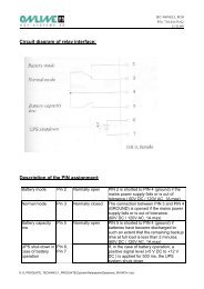
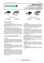
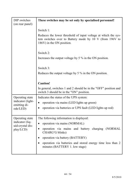
DIP switches(on rear panel)These switches may be set only by specialised personnel!Switch 1:Reduces the lower threshold of input voltage at which the systemswitches over to Battery mode by 10 V (from 196V to186V) in the ON position.Switch 2:Increases the output voltage by 5 % in the ON position.Switch 3:Reduces the output voltage by 5 % in the ON position.Operating stateindicator (lightemittingdiode/LED)Caution!In general, switches 1 and 2 should be in the "OFF" position andswitch 3 should be in the "ON" position.Indicates the status of the UPS system:operation via mains (LED lights up green)operation via batteries or UPS fault (LED lights up red)Operating stateindicator (liquid-crystaldisplay/LCD)The following information is displayed:operation via mains (NORMAL)operation via mains and battery charging (NORMALCHARG’G blinks)operation via battery (BATTERY)operation via batteries and stored energy time less than 2minutes (BATTERY 1. low stage)44 / 548/5/2010