ACCENSIONE A ROTORE INTERNO Istruzioni di Montaggio ...
ACCENSIONE A ROTORE INTERNO Istruzioni di Montaggio ...
ACCENSIONE A ROTORE INTERNO Istruzioni di Montaggio ...
- No tags were found...

You also want an ePaper? Increase the reach of your titles
YUMPU automatically turns print PDFs into web optimized ePapers that Google loves.
05/2012 - 7314398<strong>ACCENSIONE</strong> A <strong>ROTORE</strong> <strong>INTERNO</strong> <strong>Istruzioni</strong> <strong>di</strong> <strong>Montaggio</strong>INNER ROTOR IGNITION Installation InstructionsALLUMAGE A ROTOR INTERNE Instructions de MontageApplicazioni MHR MHR TEAMMoto 50 5514688 5515003Scooter Piaggioaria / air / aire5514689 -Scooter Piaggio H 2O 5514691 5515001Scooter Yamaha-Minarelli 5514690 5515002
La gamma MHR Team è dotata <strong>di</strong> centralina ad anticipo variabile con 3 trimmer:- il primo (MAPS) per determinare la selezione della mappa <strong>di</strong> anticipo- il secondo (OFFSET) permette <strong>di</strong> spostare la mappa selezionata + o – 2°- il terzo (LIM) in<strong>di</strong>cato in particolar modo per i motori 4 tempi, permette <strong>di</strong> variare l’intervento dellimitatore <strong>di</strong> giri (da 11.500 a 14.300 Rpm + limitatore escluso)È dotata inoltre <strong>di</strong> 8 mappature preimpostate che si <strong>di</strong>stinguono in:- 2 per motori 4t anticipo variabile- 5 per motori 2t anticipo variabile- 1 con anticipo fissoQuesto complessivo accensione non necessita <strong>di</strong> alcun ulteriore componente perfunzionare.Non gestisce l’impianto elettrico originale (non genera tensione per alimentare luci eservizi).The MHR Team includes a control unit with variable spark advance timing and with 3 trimmers:- the first trimmer (MAPS) is for selecting the spark advance timing map- the second trimmer (OFFSET) allows you to shift the selected map ± 2°- the third trimmer (LIM) used especially for 4-stroke engines, permits you to vary the rev limit between11.500 RPM to 14.300 RPM and also allows you to <strong>di</strong>sable the rev limiterIt also features 8 preset maps described as follows:- 2 variable spark advance maps for 4 stroke engines- 5 variable spark advance maps for 2 stroke engines- 1 fixed spark advance mapThis ignition kit does not need any further part to work.It does not affect the original electric system (it produces no voltage to feed lights andservices).la version précédente!La gamme MHR est dotée d’un boîtier électronique à avance variable non remapable.La gamme MHR Team est dotée d’un boîtier électronique à avance variable avec 3 trimmer :- le premier (MAPS) pour déterminer la sélection de courbe d’avance- le second (OFFSET) permet de déplacer la courbe sélectionnée + ou – 2°- le troisième (LIM) in<strong>di</strong>qué plus particulièrement pour les moteurs 4 temps, permet de varierl’intervention du limitateur de tours (de 11.500 à 14.300 trs/min. + limitateur exclus)En plus, il est doté de 8 courbes pré installée qui se <strong>di</strong>stingue en :- 2 pour moteurs 4T avance variable- 5 pour moteurs 2T avance variable- 1 avec avance fixeCe set d’allumage n’a besoin d’aucun autre composant pour fonctionner.Il ne gère pas le système électrique d’origine (ne génère pas de tension pour alimenterlumières et services).3
ITALIANOENGLISHDATI TECNICICentralina MHR TeamCentralina ad anticipo variabile dotata <strong>di</strong> 3 trimmer:- trimmer MAPS: selezione mappa <strong>di</strong> anticipo- trimmer OFFSET: spostamento mappa selezionata + o – 2°- trimmer LIM: variazione intervento limitatore <strong>di</strong> giri (16 posizioni possibili)- 8 mappature preimpostate:- 2 per motori 4t anticipo variabile- 5 per motori 2t anticipo variabile- 1 con anticipo fisso- Sistema basato su uP STM8 - 8 Bit con capacità <strong>di</strong> calcolo superiore @ 20 MIPS (milioni <strong>di</strong>istruzioni per secondo).- Riduzione dei tempi <strong>di</strong> calcolo, migliore precisione e stabilità dell’attuazione dell’anticipo.- Architettura hardware con miglioramento dell’immunità ai <strong>di</strong>sturbi.- Cablaggio con classe <strong>di</strong> temperatura 105°C.TECHNICAL FEATURESCDI MHR TeamControl unit with variable spark advance timing and with 3 trimmers:- trimmer MAPS: selects the spark advance timing map- trimmer OFFSET: shifts the selected map ± 2°- trimmer LIM: selects the rev limit (16 possible settings)- 8 preset maps:- 2 variable spark advance maps for 4 stroke engines- 5 variable spark advance maps for 2 stroke engines- 1 fixed spark advance map- System based on a uP STM8 - 8 bit microprocessor with a processing speed of 20MIPS(Million Instructions Per Second).- Reduced processing time, improved spark advance precision and stability.- Hardware architecture with improved immunity to interferences.- Temperature class 105°C cable.FRANÇAISCARACTÉRISTIQUES TECHNIQUESBoîtier électronique MHR TeamBoîtier électronique à avance variable doté de 3 trimmer :- trimmer MAPS : sélectionne la courbe d’avance- trimmer OFFSET : déplace la courbe sélectionnée + ou – 2°- trimmer LIM : variation du limitateur de tours (16 positions possibles)- 8 courbes pré installées:- 2 pour moteurs 4T avance variable- 5 pour moteurs 2T avance variable- 1 avec avance fixe- Système basé sur uP STM8 – 8 Bits avec capacité de calculs supérieures à 20 MIPS (Millionsd’instructions par seconde).- Réduction du temps de calcul, meilleure précision et de stabilité du moment d’avance.- Architecture hardware avec amélioration de l’immunité contre les parasites.- Câblages classe de température 105°C.4
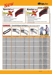
- Commutatore per compensazione errore<strong>di</strong> calettamento volano <strong>di</strong> +- 2° con<strong>di</strong>scretizzazione <strong>di</strong> 0,5°- Otto tabelle <strong>di</strong> anticipo selezionabili tramitecommutatore esterno- Vettore tabelle anticipo composto da 24breakpoint a interpolazione lineare.- Gestione del fuorigiri tramite commutatoreesterno da 16 posizioni.- Soft cut per un intervento graduale dellimitatore- 15 posizioni <strong>di</strong> regolazione limitatore da11.500 a 14.300 con step <strong>di</strong> 200 RPM, piùuna posizione per esclusione limitatoreATTENZIONE : La centralina è dotata <strong>di</strong> un limitatore<strong>di</strong> giri regolabile per evitare rotture al motore.Ruotando il trimmer con un cacciavite è possibilespostare il limitatore da 11.500 a 14.300 giri, o escluderlocompletamente. Ogni click corrisponde a 200 giri.PosizioneNr. girifrecciaO 11.500E 14.300LimitatoreFescluso- Compensation for flywheel fitting error of ± 2°with 0.5° increments via an external trimmer- 8 spark advance tables selectable via anexternal trimmer- Vector spark advance tables comprised of 24breakpoints with linear interpolation.- Adjustable rev limit via an external trimmerwith 16 settings.- Soft cut feature insures a gradual rev limit cutoff.- 15 settings to adjust the rev limit between11,500 RPM and 14,300 RPM with 200 RPMincrements plus a setting to <strong>di</strong>sable the revlimiter.ATTENTION : The control unit has an adjustable RPMlimit function to prevent engine damage. Rotating thetrimmer with a screwdriver will adjust the rpm limitbetween a range of 11,500 to 14,300, or exclude the limitfunction altogether. Every click corresponds to 200 RPMs.ArrowRPMpositionO 11.500E 14.300LimiterFswitched off- Commutateur pour compensation d’erreurde calage volant de +/- 2° avec tolérance de0,5°- 8 tableaux d’avance sélectionnable viainterrupteur externe- Vecteur tableau d’avance composé de 24breakpoint à interpolation linéaire.- Gestion des hors tours via interrupteur externeà 16 positions.- Soft cut pour intervention graduel dulimitateur.- 15 positions de réglages du limitateur de11.500 à 14.300 avec step de 200 trs/min.,plus une position excluant le limitateur.ATTENTION : Le boîtier électronique est dotée d’unlimiteur de tours réglables afin d’éviter les cassesmoteurs. En tournant le trimmer avec un tourne vis ilest possible de déplacer le limiteur de 11.500 à 14.300 toursou bien de l’enlever complètement. Chaque click correspondà 100 tours.PositionRPMflècheO 11.500E 14.300LimiteurFdésactivé5
ITALIANOCentralina MHR- Anticipo variabile- Sistema basato su uP STM8 - 8 Bit con capacità <strong>di</strong> calcolo superiore @ 20 MIPS (milioni <strong>di</strong>istruzioni per secondo).- Riduzione dei tempi <strong>di</strong> calcolo, migliore precisione e stabilità dell’attuazione dell’anticipo.- Architettura hardware con miglioramento dell’immunità ai <strong>di</strong>sturbi.- Cablaggio con classe <strong>di</strong> temperatura 105°C.- Vettore tabelle anticipo composto da 24 breakpoint a interpolazione lineare.ENGLISHCDI MHR- Variable spark advance- System based on an uP STM8 - 8 bit microprocessor with a processing speed of 20MIPS(Million Instructions Per Second).- Reduced processing time, improved spark advance precision and stability.- Hardware architecture with improved immunity to interferences.- Temperature class 105°C cable.- Vector spark advance tables comprised of 24 breakpoints with linear interpolation.FRANÇAISBoîtier électronique MHR- Avance à l’allumage variable- Système basé sur uP STM8 – 8 Bits avec capacité de calculs supérieures à 20 MIPS (Millionsd’instructions par seconde).- Réduction du temps de calcul, meilleure précision et de stabilité du moment d’avance.- Architecture hardware avec amélioration de l’immunité contre les parasites.- Câblages classe de température 105°C.- Vecteur tableau d’avance composé de 24 breakpoint à interpolation linéaire.6
Bobina alta tensione- Scarica capacitiva.- Altissimo ren<strong>di</strong>mento.- Tensione <strong>di</strong> scarica costante <strong>di</strong> 30.000 volt fino a 20.000 giri/min.Gruppo rotore-statore- Rotore interno <strong>di</strong> minime <strong>di</strong>mensioni (Ø 58 mm) e peso.- Rotore a magneti permanenti per alte prestazioni.- Massimo ren<strong>di</strong>mento.ATTENZIONE :con questo tipo <strong>di</strong> accensione l’impianto elettrico del veicolo viene escluso.High voltage coil- Capacitive <strong>di</strong>scharge- Ultra high efficiency- Constant 30,000 V <strong>di</strong>scharge voltage up to 20,000 rpmRotor-stator unit- Small (Ø 58 mm) and light inner rotor- Permanent magnet rotor ensuring excellent performance- Unprecedented efficiency with minimum weightWARNING :with this kind of ignition the lighting set is <strong>di</strong>sconnected.Bobine haute tension- Décharge capacitive- Très haut rendement- Tension de décharge constante de 30.000 volts jusqu’à 20.000 tours/minutesGroupe rotor-stator- Rotor interne de <strong>di</strong>mensions et poids réduits Ø 58 mm- Rotor à magnétos permanentes hautes performances- Rendement maxi, poids miniATTENTION :avec cet allumage l’équipement électrique est <strong>di</strong>sjoint.7
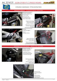
ITALIANOPER TUTTI I VEICOLI - FOR ALL VEHICLES - POUR TOUS LES VÉHICULESISTRUZIONI DI MONTAGGIO- Lavare accuratamente tutto il veicolo e in modo particolare la zona del motore su cui si andràad operare.- Scollegare e togliere la batteria.- Motori raffreddati ad aria: smontare il convogliatore aria e la ventola <strong>di</strong> raffreddamentomontati sul volano d’accensione.- Motori Minarelli: Togliere il coperchio in alluminio che supporta la pompa del liquido <strong>di</strong>raffreddamento del motore. Togliere i tre bulloncini fissati sul volano <strong>di</strong> accensione chefungono da trascinatori per la pompa del liquido <strong>di</strong> raffreddamento.- Dopo aver tolto il dado che fissa il volano d’accensione all’albero motore, smontare il volanod’accensione con gli appositi estrattori. Smontare la flangia <strong>di</strong> supporto statore / pick-up.- Smontare dal veicolo la bobina <strong>di</strong> alta tensione e la centralina originale.- Scollegare ed eliminare tutti i cavi che alimentano i restanti servizi elettrici (luci, ricarica,batteria, ecc).- Smontare lo statore originale.ENGLISHASSEMBLY INSTRUCTIONS- Thoroughly wash the whole vehicle, especially the engine area where work will beperformed.- Disconnect and remove the battery.- Air-cooled engines: remove the air pipe and the cooling fan fitted on the ignition flywheel.- Minarelli engines: remove the aluminium cover supporting the cooling fluid pump. Loosenthe three nuts driving the cooling fluid pump and remove them from the ignition flywheel.- After unscrewing the nut locking the ignition flywheel on the crankshaft, remove the ignitionflywheel by using special extractors. Remove the stator-hol<strong>di</strong>ng flange / the pick-up.- Remove the high voltage coil and the original control unit from the vehicle.- Disconnect and eliminate all cables supplying power to the other electrical devices (such aslights, charger, battery, etc.).- Remove the original stator.FRANÇAISINSTRUCTIONS DE MONTAGE- Lavez soigneusement le scooter et en particulier la zone du moteur sur laquelle devras’effectuer le montage.- Débranchez et retirez la batterie.- Moteurs à refroi<strong>di</strong>ssement à air : démontez le manchon à air et le ventilateur derefroi<strong>di</strong>ssement montés sur le volant d’allumage.- Moteurs Minarelli : démontez le couvercle en aluminium supportant la pompe du liquide derefroi<strong>di</strong>ssement. Retirez les trois boulons fixés sur le volant d’allumage assurant l’entraînementde la pompe du liquide de refroi<strong>di</strong>ssement.- Après avoir retiré l’écrou de fixation du volant d’allumage à l’arbre moteur, à l’aide desextracteurs prévus à cet effet, démontez le volant d’allumage. Démontez la bride de supportdu stator / le pick-up.- Démontez la bobine haute tension et le boîtier électronique d’origine.- Débranchez et retirez tous les autres fils d’alimentation (éclairage, recharge, batterie, etc.).- Démontez le stator d’origine.8
PIAGGIO aria / air / airePIAGGIO H 2OMONTAGGIO- Pulire accuratamente tutta la zona interna al carter motore dal lato dell’accensione compreso ilcono dell’albero motore.Motori Piaggio: Inserire nella flangia supporto statore il cavo <strong>di</strong> uscita della tensione facendolopassare completamente attraverso l’apposita asola; collocare in sede lo statore nella flangia stessa.Montare le 3 viti <strong>di</strong> fissaggio M5 in dotazione e accostarle senza chiuderle a fondo, per consentire larotazione dello statore nel momento della messa in fase.Prendere la flangia con lo statore applicato e, curando la <strong>di</strong>sposizione del cavo <strong>di</strong> corrente, montarlasul carter motore e fissarla a fondo usando le 3 viti a testa svasata M6 <strong>di</strong> corredo.Inserire accuratamente la chiavetta nell’apposita sede dell’albero motore. Montare successivamente ilrotore inserendolo perfettamente in fase con la chiavetta e, dopo averlo assestato nel cono dell’alberomotore, serrare il dado a 30 Nm (3 kgm) verificando che il rotore giri perfettamente senza toccare lepolarità dello statore. In caso contrario rimuovere le cause.Seguire le istruzioni <strong>di</strong> montaggio da pag. 13 a pag.17.ASSEMBLY- Thoroughly clean and wipe the inside of the engine casing on the ignition side, inclu<strong>di</strong>ng the outputcable.Piaggio engines: Take the stator, fit the output cable in the base plate through the proper eyelet, fitthe stator in the plate suitably, fit the 3 M5 fastening screws supplied without tighten them completelyin order to allow the stator rotation during the timing.Take the plate with the stator and, paying attention to the cable position, lock the plate onto the enginecasing by means of the 3 M6 screws supplied.Fit the key in the key seat of the crankshaft, then assemble the rotor perfectly timed with the key andafter fitting it in the crankshaft cone, tighten the rotor-locking nut applying a 30 Nm (3 kgm) torquechecking that the rotor perfectly turns without touching the stator polarities. Otherwise, eliminate thecauses.Follow the Assembly Instructions from pg. 13 to pg. 17.MONTAGE- Nettoyez soigneusement toute la partie interne du carter moteur côté allumage, y compris le cônede l’arbre moteur.Moteurs Piaggio: Prenez le stator, la bride de support du stator et introduisez dans celle-ci le câblede sortie de la tension à travers la fente spéciale. Placez le stator dans la bride, montez les 3 vis defixation M5 fournies dans le kit sans les serrer à fond afin de permettre la rotation du stator au momentde la mise en phase.Prenez la bride avec le stator en faisant attention à la position du câble de courant, montez la bridesur le carter moteur en la fixant à l’aide des 3 vis M6 fournies dans le kit.Introduisez soigneusement la clavette dans son logement de l’arbre moteur, montez ensuite le rotorparfaitement en phase avec la clavette et, après l’avoir bien placé dans le cône de l’arbre moteur,serrez l’écrou de fixation du rotor à un couple de serrage de 30 Nm (3 Kgm) en vérifiant que le rotortourne parfaitement sans toucher les polarités du stator. Dans le cas contraire, éliminez les causes.Suivez les Instruction de montage de pg. 13 à pg. 17.9
YAMAHA-MINARELLIITALIANOMotori Minarelli/Yamaha: Montare sul carter motore la flangia <strong>di</strong> supporto statore Malossiusando le 3 viti in dotazione e bloccarle a fondo con gradualità. Montare accuratamente lachiavetta nell’apposita sede dell’albero motore e successivamente il rotore facendo attenzionea metterlo in fase perfettamente con la chiavetta ed infine bloccarlo con il dado originale a 30Nm (3 kgm).Montare lo statore in modo corretto sulla flangia <strong>di</strong> supporto avendo cura <strong>di</strong> sistemare il cavoelettrico senza danneggiarlo. Fissare lo statore con le 3 viti M5 in dotazione senza bloccarlo,per consentire <strong>di</strong> effettuare me<strong>di</strong>ante rotazione manuale dello statore stesso una correttamessa in fase. Accertarsi che il rotore giri liberamente senza problemi altrimenti rimuovere gliimpe<strong>di</strong>menti.Seguire le istruzioni <strong>di</strong> montaggio da pag. 13 a pag.17.ENGLISHMinarelli/Yamaha engines: Fit the Malossi base plate on the engine casing by graduallytightening the 3 screws provided, carefully fit the key in its seat of the crankshaft and then fitthe rotor perfectly timed with the key and tighten the rotor-locking nut by applying a 30 Nm (3kgm) torque.Assemble the stator on the hol<strong>di</strong>ng flange correctly and fit the cable without damaging it.Secure the stator by means of the 3 M5 screws supplied without locking it in order to allow acorrect timing by manual rotation of the stator. Make sure that the rotor turns without problems,otherwise eliminate the causes.Follow the Assembly Instructions from pg. 13 to pg. 17.FRANÇAISMoteurs Minarelli/Yamaha: Montez la bride de support du stator Malossi en la fixant aucarter moteur à l’aide des 3 vis fournies à cet effet en les serrant graduellement à fond, montezsoigneusement la clavette dans son logement de l’arbre moteur. Ensuite, montez le rotorparfaitement en phase avec la clavette en le bloquant à l’aide de l’écrou d’origine à un couplede serrage de 30 Nm (3 Kgm).Montez correctement le stator sur la bride de support en ayant soin de placer le câble électriquesans l’endommager. Fixez le stator à l’aide des 3 vis de fixation M5 fournies à cet effet sans lesserrer à fond pour permettre d’effectuer une mise en phase correcte par la rotation manuelle dustator. Vérifiez que le rotor tourne sans problème; dans le cas contraire, éliminez les causes.Suivez les Instruction de montage de pg. 13 à pg. 17.10
Moto 50 (Minarelli AM 3/4/5/6 - Derbi EBE050 / EBS050 / D50B0 / D50B1)MONTAGGIO e MESSA IN FASE DELL’<strong>ACCENSIONE</strong>- Collocare in sede sul carter motore lo statore.- Montare le 3 viti <strong>di</strong> fissaggio in dotazione e accostarle senza chiuderle a fondo, per consentire larotazione dello statore nel momento della messa in fase (ove possibile).- Eliminare la chiavetta originale.- Ruotare il motore in senso orario fino a raggiungere il punto morto superiore e azzerare ilcomparatore, verificando più volte l’esattezza dell’operazione.- Procedere con la rotazione del motore in senso orario fino a quando il comparatore segna la<strong>di</strong>stanza in<strong>di</strong>cata in Tabella 3 (anticipo calettamento statico) dal punto morto superiore.- Tenere ben fermo l’albero motore in questa posizione e fare collimare la linea <strong>di</strong> riferimentoimpressa sul rotore con quella situata sullo statore me<strong>di</strong>ante la rotazione del rotore.ASSEMBLY and IGNITION TIMING- Fit the stator on the crankcase.- Fit the 3 fastening screws supplied without tighten them completely in order to allow the statorrotation during the timing (if possible).- Eliminate the original key.- Turn the engine clockwise to the top dead centre and zero the <strong>di</strong>al in<strong>di</strong>cator checking the exactitudeof the operation.- Go on with the clockwise engine rotation until the <strong>di</strong>al in<strong>di</strong>cator marks the <strong>di</strong>stance in<strong>di</strong>cated inTable 3 (static keying advance) from the top dead centre.- Keeping the crankshaft in this position, align the reference mark on the rotor with the mark drawnon the stator by turning the rotor.MONTAGE et MISE EN PHASE DE L’ALLUMAGE- Placez le stator dans le carter.- Montez les 3 vis de fixation fournies dans le kit sans les serrer à fond afin de permettre la rotationdu stator au moment de la mise en phase (si possible).- Retirez la clavette d’origine.- Tournez l’arbre moteur dans le sens des aiguilles d’une montre jusqu’au point mort supérieur etmettez au zéro le comparateur, en vérifiant plusieurs fois l’exactitude de l’opération.- Faites tourner l’arbre moteur dans le sens des aiguilles d’une montre jusqu’à que le comparateurin<strong>di</strong>que la <strong>di</strong>stance donnée dans la Table 3 (avance calage statique) du point mort supérieur.- Gardez l’arbre moteur dans cette position, faites coïncider le repère tracé sur le rotor avec celuiprésent sur le stator par rotation du rotor.11
Moto 50 (Minarelli AM 3/4/5/6 - Derbi EBE050 / EBS050 / D50B0 / D50B1)ITALIANO- Assestare il rotore nel cono dell’albero motore, serrare il dado a 30 Nm (3 kgm) verificandoche il rotore giri perfettamente senza toccare le polarità dello statore. In caso contrariorimuovere le cause.- Bloccare a fondo le tre viti <strong>di</strong> fissaggio dello statore.Seguire le istruzioni <strong>di</strong> montaggio pag. 14/17.ENGLISH- Assemble the rotor in the crankshaft cone, tighten the rotor-locking nut applying a 30 Nm(3 kgm) torque checking that the rotor perfectly turns without touching the stator polarities.Otherwise, eliminate the causes.- Tighten the three stator fastening screws.Follow the Assembly Instructions page 14/17.FRANÇAIS- Introduisez le rotor dans le cône de l’arbre moteur, serrez l’écrou de fixation du rotor à uncouple de serrage de 30 Nm (3 Kgm) en vérifiant que le rotor tourne parfaitement sanstoucher les polarités du stator. Dans le cas contraire, éliminez les causes.- Serrez à fond les trois vis de fixation du stator.Suivez les Instruction de montage page 14/17.12
PIAGGIO aria / air / aire PIAGGIO H 2O (Segue da pag. 9 - continued from page 9 - suite de page 9)YAMAHA-MINARELLI (Segue da pag. 10 - continued from page 10 - suite de page 10)MESSA IN FASE DELL’<strong>ACCENSIONE</strong>Ruotare il motore in senso antiorario fino a raggiungere il punto morto superiore e azzerare ilcomparatore, verificando più volte l’esattezza dell’operazione. Procedere con la rotazione del motorein senso antiorario fino a quando il comparatore segna la <strong>di</strong>stanza in<strong>di</strong>cata in Tabella 1 (anticipocalettamento statico) dal punto morto superiore. Tenere ben fermo l’albero motore in questa posizionee fare collimare la linea <strong>di</strong> riferimento impressa sul rotore con quella situata sullo statore me<strong>di</strong>ante larotazione <strong>di</strong> quest’ultimo, poi bloccare a fondo le tre viti <strong>di</strong> fissaggio dello statore.IGNITION TIMINGTurn the engine anti-clockwise to the top dead centre and zero the <strong>di</strong>al in<strong>di</strong>cator checking theexactitude of the operation. Go on with the anti-clockwise engine rotation until the <strong>di</strong>al in<strong>di</strong>catormarks the <strong>di</strong>stance in<strong>di</strong>cated in Table 1 (static keying advance) from the top dead centre. Keeping thecrankshaft in this position, align the reference mark on the rotor with the mark drawn on the stator byturning the stator, then tighten the three stator fastening screws.MISE EN PHASE DE L’ALLUMAGETournez l’arbre moteur dans le sens contraire des aiguilles d’une montre jusqu’au point mort supérieuret mettez au zéro le comparateur, en vérifiant plusieurs fois l’exactitude de l’opération. Faites tournerl’arbre moteur dans le sens contraire des aiguilles d’une montre jusqu’à que le comparateur in<strong>di</strong>quela <strong>di</strong>stance donnée dans la Table 1 (avance calage statique) du point mort supérieur. Gardez l’arbremoteur dans cette position, faites coïncider le repère tracé sur le rotor avec celui présent sur le statorpar rotation de celui-ci, ensuite serrez à fond les trois vis de fixation du stator.13
ITALIANOPER TUTTI I VEICOLI - FOR ALL VEHICLES - POUR TOUS LES VÉHICULESCOLLEGAMENTI ELETTRICI- Montare la nuova bobina ad alta tensione Malossi curando scrupolosamente la messa amassa della stessa e montare il cavo candela.- Collegare il cavetto nero con terminale ad occhiello e faston piccolo al terminale piccolo dellabobina e con l’occhiello alla massa della bobina.È buona norma fissare un unico punto <strong>di</strong> massa per l’impianto accensione al quale vannocollegate la massa della bobina (filo nero), la massa della centralina (filo nero con terminalead occhiello) e la massa fisica della bobina <strong>di</strong> alta tensione (ve<strong>di</strong> schema pag. 19).- Montare la nuova centralina elettronica Malossi sul veicolo sostituendo quella originale.- Allacciare i cavi in uscita dallo statore alla centralina tramite relativi spinotti.- Collegare il cavo arancione con il faston grande al terminale grande della bobina <strong>di</strong> altatensione.ENGLISHFRANÇAISELECTRICAL CONNECTIONS- Insert the new Malossi high voltage coil and carefully ground it. Connect the spark wire.- The black cable with the eyebolt terminal and the small faston must be connected to thesmall coil terminal. The eyebolt must be connected to the coil ground.It is recommended that a single groun<strong>di</strong>ng point for the whole ignition system should be used,where the coil earth wire (black), the control unit earth wire (black with eyebolt terminal) andthe earth wire of the high voltage coil (see <strong>di</strong>agram pg. 19) should be connected.- Assemble the new Malossi electronic control unit on the vehicle.- Connect the stator cables to the control unit by means of the cable terminal plug.- Connect the orange cable provided with the big faston to the big terminal on the high voltagecoil.- Connect the black control unit cable to the common ground terminal of the new system (see<strong>di</strong>agram pg. 19).CONNEXIONS ELECTRIQUES- Montez la bobine haute tension Malossi en veillant à bien la raccorder à la masse et montezle fil de bougie.- Le fil noir avec œillet et faston de connexion doit être raccordé à la petite borne de la bobineet à l’œillet de masse de la bobine.Il est recommandé de fixer un unique point de masse pour le système d’allumage auquel doiventêtre raccordées la masse de la bobine (fil noir), la masse du boîtier électronique (fil noir avecœillet de connexion) et la masse physique de la bobine haute tension (voir schéma pg. 19).- Montez sur le scooter le boîtier électronique Malossi.- Raccordez les fils du stator au boîtier électronique par l’intermé<strong>di</strong>aire des connecteursprésents sur les fils.- Raccordez le fil orange à grand connecteur faston à la grande borne de la bobine hautetension.14
PER TUTTI I VEICOLI - FOR ALL VEHICLES - POUR TOUS LES VÉHICULES- Collegare il cavo nero della centralina con il terminale ad occhiello sotto la vite comune delle massedel nuovo impianto (ve<strong>di</strong> schema pag. 19).- Cavo rosso per interruttore stop motore.- Collegare il cavo rosso all’interruttore (NON fornito nel kit), collegando quest’ultimo a massa.Questo collegamento non è in<strong>di</strong>spensabile per il corretto funzionamento dell’accensione a rotoreinterno.- Red wire for engine kill switch.- Connect the red wire to the switch (NOT included in the kit), ground the switch.This is not a necessary connection for the correct operation of an ignition with an internal rotor.- Raccordez le fil noir du boîtier électronique à la borne commune des masses du nouveau système(voir schéma pg. 19).- Fil rouge pour stop moteur.- Raccordez le fil rouge à l’interrupteur (NE PAS fourni dans le kit), en reliant ce dernier à la masse.Cette connexion n’est pas in<strong>di</strong>spensable pour le correct fonctionnement de l’allumage à rotorinterne.15
ITALIANOPER TUTTI I VEICOLI - FOR ALL VEHICLES - POUR TOUS LES VÉHICULESVERIFICA MESSA IN FASE CON PISTOLA STROBOSCOPICASe <strong>di</strong>sponete <strong>di</strong> una buona pistola stroboscopica dotata <strong>di</strong> <strong>di</strong>splay per leggere l’anticipo in gra<strong>di</strong>,potete effettuare un controllo <strong>di</strong>namico procedendo come segue. Portare il motore al punto mortosuperiore e usando un pennarello a punta fine o una punta da segni, tracciare sul rotore unalinea esattamente in corrispondenza con quella impressa sullo statore. Togliere il comparatore,rimontare la candela e collegarla al filo <strong>di</strong> alta tensione, collegare la pistola stroboscopica eavviare il motore stabilizzandolo sui 4000 giri al minuto primo. Agire sul rullino collimatore dellapistola e far coincidere il segno sullo statore con quello che avete creato sul rotore. Se tutto éstato fatto correttamente si dovrebbe leggere sul quadrante della pistola l’angolo <strong>di</strong> anticipoin<strong>di</strong>cato in Tabella 1 con tolleranza 2° gra<strong>di</strong>.Per avere un buon funzionamento dell’accensione si consiglia <strong>di</strong> regolare la <strong>di</strong>stanza fra glielettro<strong>di</strong> della candela 0,45 mm.ENGLISHTIMING CHECK WITH STOBOSCOPE GUNIf you have a good stroboscope gun with a <strong>di</strong>splay to read the spark advance degrees, you canmake a dynamic check as follows. Drive the motor to its top dead centre and, by using a thin tippen or a drawpoint, mark on the rotor a reference mark where it matches the mark on the stator.Remove the <strong>di</strong>al in<strong>di</strong>cator, fit the spark plug connecting it to the high-voltage cable, connect thestroboscope gun and start the engine stabilizing it at 4,000 rpm. By using the gun collimatoralign the reference mark on the stator with the mark drawn on the rotor. If all the operations wereproperly performed, the gun <strong>di</strong>splay should show the advanced angle as in<strong>di</strong>cated in Table 1(± 2° degrees).In order to have a good ignition, having care to check that the <strong>di</strong>stance between electrodes ofthe spark plug is 0.45 mm.FRANÇAISCONTRÔLE MISE EN PHASE AVEC STOBOSCOPESi vous avez un bon stroboscope équipé d’un écran pour lire l’avance en degrés, vous pouvezeffectuer un contrôle dynamique comme suit. Amenez le moteur au point mort supérieur et àl’aide d’un feutre à pointe fine ou d’une pointe à tracer, marquez sur le rotor une ligne parfaitementcorrespondante à celle tracée sur le stator. Enlevez le comparateur, remontez la bougie en laconnectant au câble de haute tension, connectez le stroboscope et faites démarrer le moteur enle stabilisant à un régime de 4000 tours/minutes. A l’aide du collimateur du stroboscope, faitescoïncider le cran sur le stator avec celui tracé précédemment sur le rotor. Si toute l’opération aété effectuée correctement, sur le cadran du stroboscope on devrait lire l’angle d’avance commein<strong>di</strong>qué dans le Tableau 1 (± 2° degrés).Pour un bon fonctionnement de l’allumage, il est recommandé de régler la <strong>di</strong>stance entre lesélectrodes de la bougie à 0,45 mm.16
PER TUTTI I VEICOLI - FOR ALL VEHICLES - POUR TOUS LES VÉHICULESMotori Piaggio raffreddati a liquido ( 5514691 - 5514688 ) : montare il volano d’inerzia in dotazionee rimontare il coperchio in plastica del carter motore lato accensione.Motori Minarelli/Yamaha raffreddati a liquido - pompa sul carter ( 5514690 ): montare la flangia <strong>di</strong>trascinamento Malossi sul rotore e le tre viti <strong>di</strong> trascinamento della pompa del liquido <strong>di</strong> raffreddamentosulla flangiaMotori Minarelli/Piaggio raffreddati ad aria ( 5514690 - 5514689 ): montare sul rotore la flangia <strong>di</strong>trascinamento della ventola e la ventola <strong>di</strong> raffreddamento originale. Rimontare tutto il convogliatorearia originale.Motori Piaggio raffreddati ad aria prima serie dotati <strong>di</strong> ventola semplice: occorre abbassarela ventola stessa me<strong>di</strong>ante tornitura delle pale per una quota <strong>di</strong> 5 mm. Negli Scooter dell’ultimagenerazione che montano una ventola flangiata si consiglia <strong>di</strong> sostituirla con una originale della primaserie e mo<strong>di</strong>ficarla come anzi descritta.Piaggio water-cooled engines ( 5514691 - 5514688 ) : fit the inertial flywheel supplied and theplastic cover back on the engine casing ignition side.Minarelli/Yamaha water-cooled engines - pump on the casing ( 5514690 ): assemble the Malossidriving flange onto the rotor and fit the three screws driving the cooling fluid pump into the flange.Minarelli/Piaggio Air-cooled engines ( 5514690 - 5514689 ): assemble the fan driving flange and theoriginal cooling fan onto the rotor. Re-assemble the original air manifold.Piaggio 1 st series air-cooled engines provided with simple fan: lower the fan by 5 mm by movingthe blades. In case of scooters belonging to the latest generation and provided with flange-type fans,replace the fan with a 1st series original one and mo<strong>di</strong>fy it as described above.Moteurs Piaggio à refroi<strong>di</strong>ssement liquide ( 5514691 - 5514688 ) : montez le volant d’inertie fournidans le kit et remontez le couvercle en plastique du carter moteur côté allumageMoteurs Minarelli/Yamaha à refroi<strong>di</strong>ssement liquide - pompe sur carter ( 5514690 ): montez labride d’entraînement Malossi sur le rotor et les trois vis d’entraînement de la pompe du liquide derefroi<strong>di</strong>ssement sur la bride.Moteurs Minarelli/Piaggio à refroi<strong>di</strong>ssement à air ( 5514690 - 5514689 ): montez sur le rotorla bride d’entraînement du ventilateur et le ventilateur de refroi<strong>di</strong>ssement d’origine. Remontez lemanchon d’air d’origineMoteurs Piaggio à refroi<strong>di</strong>ssement à air 1ère série dotés de ventilateur simple: il est nécessaired’abaisser le ventilateur par tournage des pales sur 5 mm, alors que sur les scooters de la dernièregénération, lesquels sont équipés d’un ventilateur bridé, il est conseillé de remplacer celui-ci par unventilateur d’origine première série à mo<strong>di</strong>fier comme in<strong>di</strong>qué précédemment.17
ITALIANOSperiamo che lei abbia trovato sufficientemente esaustive le in<strong>di</strong>cazioni che precedono. Nelcaso in cui qualche punto le risultasse poco chiaro, potrà interpellarci per iscritto compilandol’apposito modulo inserito nella sezione “contatti” del ns. sito Internet (www.malossi.com).Ringraziamo fin d’ora per le osservazioni e suggerimenti che vorrà eventualmente farci pervenire.La Malossi si commiata e coglie l’occasione per complimentarsi ulteriormente con Lei edaugurarle un Buon Divertimento. In BOCCA al LUPO e ... alla prossima.Le descrizioni riportate nella presente pubblicazione, si intendono non impegnative. Malossi siriserva il <strong>di</strong>ritto <strong>di</strong> apportare mo<strong>di</strong>fiche, qualora lo ritenesse necessario, al fine <strong>di</strong> migliorare ilprodotto, e non si assume nessuna responsabilità per eventuali errori tipografici e <strong>di</strong> stampa. Lapresente pubblicazione sostituisce ed annulla tutte le precedenti riferite agli aggiornamenti trattati.GARANZIA: Consulta le con<strong>di</strong>zioni relative alla garanzia sul nostro sito www.malossi.com.Prodotti riservati esclusivamente alle competizioni nei luoghi ad esse destinate secondole <strong>di</strong>sposizioni delle competenti autorità sportive. Decliniamo ogni responsabilità per l’usoimproprio.ENGLISHWe hope you found the above instructions sufficiently clear. However, if any points are notparticularly clear, please contact us completing the special form inserted in the “contact”section on our Internet site (www.malossi.com). We thank you in advance for any commentsand suggestions you may wish to send us. So goodbye from us all at Malossi, and please acceptour compliments. Have Fun. GOOD LUCK and … see you next time.The descriptions in this publication are not bin<strong>di</strong>ng. Malossi reserves the right to makemo<strong>di</strong>fications, if it considers them necessary, and does not accept any responsibility for anytypographic or printing errors. This publication replaces all previous publications referring to theupdating matters contained therein.WARRANTY: Look up warranty terms in our website www.malossi.com.These products are reserved solely for races in locations reserved for those purposes an<strong>di</strong>n accordance with the regulations issued by the competent authorities for sports events.We decline any and all responsibility for improper use.FRANÇAISNous espérons que vous avez trouvé suffisamment claire les in<strong>di</strong>cations qui ont précédé. Dansle cas ou certains points ne vous seraient pas clairs, ils vous est possible de nous interpeller enremplissant le module se trouvant dans la section “contact” de notre site internet (www.malossi.com). Nous vous remercions d’avance des éventuelles observations et suggestions que vousvoudrez bien nous faire parvenir. Malossi prend maintenant congé et profite de l’occasion pourvous féliciter une fois encore et vous souhaiter un Bon Divertissement. BONNE CHANCE et…àla prochaine!18Les descriptions reportées dans cette publication n’engagent à rien. Malossi se réserve le droitd’apporter toutes les mo<strong>di</strong>fications qu’elle jugera nécessaires et décline toute responsabilitépour d’éventuelles coquilles et erreurs d’impression. Cette publication remplace et annulletoutes les publications précédentes relatives aux thèmes mis à jour.GARANTIE: Consultez les con<strong>di</strong>tions relatives à la garantie sur notre site www.malossi.com.Ces articles sont uniquement destinés aux compétitions dans les lieux qui leur sontréservés, conformément aux <strong>di</strong>spositions des autorités sportives compétentes. Nousdéclinons toute responsabilité en cas d’utilisation abusive.
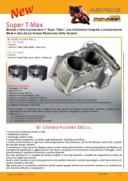
Cavo nero terminale ad occhielloBlack cable eyebolt terminalFil noir oeillet de connexionCentralina elettronicaElectronic coilBoîtier électroniqueComplessivo vitiScrews kitEnsemble visFlangia fissaggio statoreStator fixing flangeBride fissation statorRotoreRotorRotorRiferimentiReference marksRepéresCavo rosso per interruttore stop motoreRed wire for engine kill switchFil rouge pour stop moteurCavo arancione faston grande neroOrange cable big black fastonFil orange grand connecteur faston noirCollegare massa sul veicoloConnect the earth wire to the vehicleRaccorder la masse sur le scooterStatoreStatorStatorMassa motoreEngine earthMasse du moteurBobina alta tensioneHigh voltage coilBobine haute tensionCavetto NERO in dotazione TERMINATORE A FASTON piccolo biancoBLACK cable provided small white FASTON TERMINALFil NOIR fourni petit FASTON de connexion BLANC19
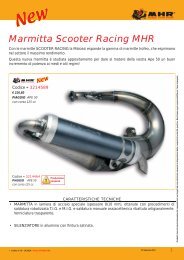
SETTAGGIO CENTRALINAAl fine <strong>di</strong> facilitare il settaggio potete trovare <strong>di</strong> seguitole in<strong>di</strong>cazioni relative al vostro tipo <strong>di</strong> motore.Oltre a ciò è <strong>di</strong>sponibile un grafico a pag.xx nel qualesono confrontate le <strong>di</strong>verse curve <strong>di</strong> anticipo.------------------------------------------------------------CDI SETTINGIn order to facilitate the setting you can find below theinformation about your type of engine. In ad<strong>di</strong>tion, atpg. 22-23 you can find a graph with <strong>di</strong>fferent advancetiming comparison.------------------------------------------------------------REGLAGE BOÎTIERAfin de faciliter le réglage, vous trouverez ci-dessousles informations sur votre type de moteur. Enoutre, il est <strong>di</strong>sponible à la pg. 22-23 un graphe decomparaison des <strong>di</strong>fférents courbes d’avance.Posizione trimmer MAPSTrimmer MAPS positionPosition trimmer MAPS0 50-70 ccanticipo fisso1 fixed advanceavance fixe2 70 cc3 80 cc4 90 cc A5 90 cc B6 4t A7 4t BNOTA BENE:fare molta attenzione a non confondere le mappature 2T e 4T!!!L’errato settaggio provocherà la rottura del motore!-------------------------------------------------------------------------------------------NOTE:be careful not to confuse the 2T and 4T maps! The incorrect settingwill cause the engine failure!-------------------------------------------------------------------------------------------NOTE:attention à ne pas confondre les courbes 2T et 4T! Le réglage incorrectprovoquera la défaillance du moteur!20
GRUPPO TERMICOCYLINDER KITGROUPE THERMIQUERAFFREDDAMENTOCOOLINGREFROIDISSEMENTDISTRIBUZIONETIMING SYSTEMDISTRIBUTIONALESAGGIO mmBORE mmALESAGE mmCORSA mmSTROKE mmCOURSE mmCILINDRATA mmCAPACITY mmCYLINDREE mmSQUISHRAPP. <strong>di</strong> COMPRESS.COMPRESSION RATIORAPP. de COMPR.(Fig. 1)ANTICIPO CALETTAMENTO STATICOSTATIC KEYING ADVANCEAVANCE CALAGE STATIQUEVERIFICA ANTICIPO CON PISTOLA STROBOSCOPICAADVANCE CHECK WITH STOBOSCOPE GUNCONTRÔLE AVANCE AVEC STOBOSCOPE31 8881 A 6 T 40 39,3 49,38 0,4 1:16,5 2,2mm31 8884 H 2O 6 T 40 39,3 49,38 0,5 1:16,5 2.2mm3111511 H 2O 6 T 40 39,2 49,26 0,5 1:16,5 2.2mm3111584 H 2O 6 T 47,6 39,3 69,93 0,45 1:15,8 2.2mm3112099 H 2O 7 T 47,6 39,3 69,93 0,45 1:15,8 2.2mm3112099.T0 H 2O 7 T 47,6 39,3 69,93 0,45 1:15,8 2,2mm3112371 H 2O 5 T 39,88 40 49,6 0,45 1:16,0 3.2mm3112376 H 2O 5 T 50 40 78,6 0,55 1:15,4 3.2mm3112381 H 2O 5 T 40,3 39 49,7 0,55 1:16,3 3.2mm3112386 H 2O 5 T 50 39,2 76,4 0,55 1:15,2 2.2mm3112642 H 2O 7 T 47,6 39,2 69,75 0,45 1:15,8 2.2mm3112642.T0 H 2O 7 T 47,6 39,2 69,75 0,45 1:15,8 2.2mm3112981 H 2O 5 T 39,88 40 49,6 0,45 1:16,0 3.2mm3112988 H 2O 7 T 50 40 78,6 0,55 1:15,4 3.2mm3113030 H 2O 7 T 50 39,3 77,15 0,5 1:15,5 2.2mm3113036 H 2O 7 T 50 39,2 77 0,5 1:15,5 2.2mm3113039 H 2O 7 T 50 44 86,4 0,8 1:15,1 2.3mm3113039.T0 H 2O 7 T 50 44 86,4 0,8 1:15,1 2.3mm3113042 H 2O 7 T 50 44 86,4 0,8 1:15,1 2.3mm3113042.T0 H 2O 7 T 50 44 86,4 0,8 1:15,1 2.3mm3113262 H 2O 7 T 47,6 39,2 69,75 0,45 1:15,8 2.2mm3115142 H 2O 7 T 47,6 39,3 69,93 0,45 1:15,8 2.2mm3115142.T0 H 2O 7 T 47,6 39,3 69,93 0,45 1:15,8 2,2mmTabella / Table / Tableau 1Fig. 132°--> 33° • ATTENZIONE:nelle centraline MHR Team èNECESSARIO selezionare laMAPPA 0• WARNING:with MHR Team CDI you MUSTselect the MAP 0• ATTENTION:dans les boîtiers MHR Teamil FAUT sélectionner laCOURBE 021
GRADIDEGREESDEGRÉS36353433323130292827262524232221201918171615141312111098765432100 1000222000Posizione trimmer MAPSTrimmer MAPS positionPosition trimmer MAPS30004000Grafico comparativoComparison chartTableau de comparaison50006000012345677000
curve <strong>di</strong> anticipoof advance timingdes courbes d’avance80009000100001100012000130001400015000 RPM23
05/2012 - 7314398.A0SETTAGGIO CENTRALINACDI SETTINGREGLAGE BOÎTIERtrimmer LIM trimmer OFFSET trimmer MAPSStep 200 RPM -+50-70 cc(x)11.50004t B(•)14.300-0,5+0,5-1+14t A70 cc(x) Limitatore esclusoLimiter switched offLimiteur désactivé-1,5-20+2+1,590 cc B90 cc A(•) anticipo fissofixed advanceavance fixe80 cc24
MHR MHR TEAMMHR MHR TEAMBOOSTER NG / NAKED / ROCKET 50 2T euro 2 5514690 5515002EVOLIS 50 2T 5514690 5515002FIZZ 50 2T 5514690 5515002FLIPPER 50 2T 5514690 5515002FORTE 50 2T 5514690 5515002MACH G 50 2T / 50 2T LC 5514690 5515002NITRO 50 2T LC 5514690 5515002OVETTO 50 2T 5514690 5515002STUNT 50 2T euro 0-1-2 5514690 5515002TARGET 50 2T 5514690 5515002PIAGGIO DIESIS 50 2T 5514689 -FLY 50 2T 5514689 -FREE 50 2T 5514689 -LIBERTY 50 2T 5514689 -NRG 50 2T LC 5514691 5515001NRG EXTREME 50 2T 5514689 -NRG EXTREME 50 2T LC 5514691 5515001NRG MC2 50 2T LC 5514691 5515001NRG MC3 DD 50 2T LC 5514691 5515001NRG MC3 DT 50 2T 5514689 -NRG Power DD 50 2T LC 5514691 5515001NRG Power DT 50 2T (C453M) 5514689 -NTT 50 2T LC 5514691 5515001QUARTZ 50 2T LC 5514691 5515001SFERA RESTYLING 50 2T 5514689 -TYPHOON 50 2T 2007->2010 5514689 -TYPHOON 50 2T euro 2 2011 5514689 -ZIP 50 2T 5514689 -ZIP 50 2T 2000 5514689 -ZIP Fast Rider 50 2T 5514689 -ZIP SP 50 2T LC 5514691 5515001VESPA ET2 50 2T 2000 5514689 -ET2 carb. 50 2T 5514689 -LX 50 2T 5514689 -S 50 2T euro 2 (C381M) 5514689 -YAMAHA AEROX 50 2T LC euro 0-1-2 5514690 5515002AXIS 50 2T 5514690 5515002BREEZE 50 2T 5514690 5515002BW’S - BW’S NG 50 2T euro 0-1 5514690 5515002BW’S - BW’S NG 50 2T euro 2 (A137E) 5514690 5515002BW’S Original/Naked 50 2T euro 2 2010 (A137E) 5514690 5515002CRZ 50 2T 5514690 5515002JOG 50 2T 5514690 5515002JOG ER 50 2T 5514690 5515002JOG R 50 2T 5514690 5515002JOGRR 50 2T LC euro 2 5514690 5515002NEO’S 50 2T 5514690 5515002SLIDER 50 2T 5514690 5515002SPY 50 2T 5514690 5515002MHR MHR TEAMVINO 50 2T 5514690 5515002WHY 50 2T 5514690 5515002ZEST 50 2T 5514690 5515002MOTOAPRILIA MX 50 2T LC (MINARELLI AM 6) 5514688 5515003RS 50 2T LC (MINARELLI AM 3 > 6) 5514688 5515003RS 50 2T LC euro 2 2006-> (DERBI D50B1) 5514688 5515003RX - SX 50 2T LC 2007-> (DERBI D50B0) 5514688 5515003TUONO 50 2T LC (MINARELLI AM 6) 5514688 5515003BETA ENDURO RR 50 2T LC (MINARELLI AM 6) 5514688 5515003ENDURO RR RACING 50 2T LC (MINARELLI AM 6) 5514688 5515003SUPERMOTARD RR 50 2T LC (MINARELLI AM 6) 5514688 5515003SUPERMOTARD RR ALU 50 2T LC (MINARELLI AM 6) 5514688 5515003DERBI GPR RACING 50 2T LC (EBS050) 5514688 5515003GPR NUDE 50 2T LC 2006-> (D50B0) 5514688 5515003GPR RACING 50 2T LC 2004-> (EBS050) 5514688 5515003GPR RACING 50 2T LC 2006-> (D50B0) 5514688 5515003SENDA 50 2T LC (EBE050 - EBS050) 5514688 5515003Senda DRD PRO R 50 2T LC (D50B0) 5514688 5515003Senda DRD PRO SM 50 2T LC (D50B0) 5514688 5515003Senda DRD RACING R - SM 50 2T LC (D50B0) 5514688 5515003Senda EVO SM 50 2T LC (D50B0) 5514688 5515003Senda X-RACE R - X-RACE SM 50 2T LC (D50B0) 5514688 5515003Senda X-TREME R - X-TREME SM 50 2T LC (D50B0) 5514688 5515003FANTIC CABALLERO 50 2T LC (MINARELLI AM 6) 5514688 5515003GILERA GSM H@K 50 2T LC (DERBI EBE050) 5514688 5515003RCR - SMT 50 2T LC (DERBI D50B0) 5514688 5515003HM CR E DERAPAGE 50 2T LC (MINARELLI AM 6) 5514688 5515003DERAPAGE RR 11 50 2T LC (MINARELLI AM 6) 5514688 5515003HUSQVARNA CH RACING 50 2T LC (MINARELLI AM 6) 5514688 5515003MALAGUTI XSM - XTM 50 2T LC (MINARELLI AM 6) 5514688 5515003MBK X-LIMIT 50 2T LC (MINARELLI AM 6) 5514688 5515003X-POWER 50 2T LC (MINARELLI AM 6) 5514688 5515003PEUGEOT XPS 50 2T LC (MINARELLI AM 6) 5514688 5515003XR6 50 2T LC (MINARELLI AM 6) 5514688 5515003XR7 50 2T LC (MINARELLI AM 6) 5514688 5515003RIEJU RS2 50 2T LC (MINARELLI AM 6) 5514688 5515003SHERCO HRD 50 2T LC (MINARELLI AM 6) 5514688 5515003YAMAHA DT 50 R 50 2T LC euro 2 (MINARELLI AM 6) 5514688 5515003DT 50 X 50 2T LC euro 2 (MINARELLI AM 6) 5514688 5515003TZR 50 2T LC (MINARELLI AM 6) 5514688 5515003ATV-QUADDRX 90 2T 5514690 (*) 5515002 (*)(*) Solo con art. / Only with art. / Seulem. avec art. 4914600malossi.comSCOOTERAPRILIA AREA 51 50 2T LC 5514690 5515002MOJITO CUSTOM 50 2T 5514689 -RALLY 50 2T / 50 2T LC (MINARELLI) 5514690 5515002SCARABEO STREET 50 2T (PIAGGIO) 5514689 -SONIC 50 2T / 50 2T LC 5514690 5515002SPORTCITY ONE STREET 50 2T euro 2 5514689 -SR 50 2T 1994-> 5514690 5515002SR (carb.) 50 2T LC 2004 (PIAGGIO) 5514691 5515001SR NETSCAPER 50 2T LC (MINARELLI) 5514690 5515002SR R (carb.) 50 2T LC (PIAGGIO) 5514691 5515001SR RACING 50 2T LC (MINARELLI) 5514690 5515002SR REPLICA 50 2T LC 5514690 5515002SR STEALTH 50 2T LC (MINARELLI) 5514690 5515002SR WWW 50 2T 5514690 5515002BENELLI 491 GT 50 2T (MINARELLI) 5514690 5515002491 SPORT 50 2T LC (MINARELLI) 5514690 5515002K2 50 2T / 50 2T LC 5514690 5515002NAKED 50 2T 5514690 5515002BETA ARK 50 2T / 50 2T LC 5514690 5515002EIKON 50 2T LC 5514690 5515002CPI HUSSAR 50 2T