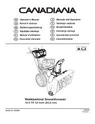
Walkbehind Snowthrower - Canadiana
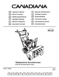
Walkbehind Snowthrower - Canadiana
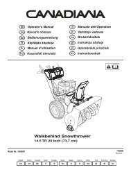
Walkbehind Snowthrower - Canadiana
- No tags were found...

You also want an ePaper? Increase the reach of your titles
YUMPU automatically turns print PDFs into web optimized ePapers that Google loves.
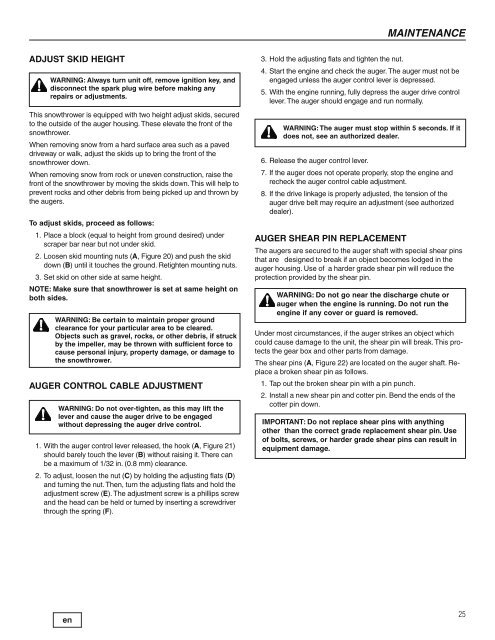
MAINTENANCEADJUST SKID HEIGHTWARNING: Always turn unit off, remove ignition key, anddisconnect the spark plug wire before making anyrepairs or adjustments.This snowthrower is equipped with two height adjust skids, securedto the outside of the auger housing. These elevate the front of thesnowthrower.When removing snow from a hard surface area such as a paveddriveway or walk, adjust the skids up to bring the front of thesnowthrower down.When removing snow from rock or uneven construction, raise thefront of the snowthrower by moving the skids down. This will help toprevent rocks and other debris from being picked up and thrown bythe augers.To adjust skids, proceed as follows:1. Place a block (equal to height from ground desired) underscraper bar near but not under skid.2. Loosen skid mounting nuts (A, Figure 20) and push the skiddown (B) until it touches the ground. Retighten mounting nuts.3. Set skid on other side at same height.NOTE: Make sure that snowthrower is set at same height onboth sides.WARNING: Be certain to maintain proper groundclearance for your particular area to be cleared.Objects such as gravel, rocks, or other debris, if struckby the impeller, may be thrown with sufficient force tocause personal injury, property damage, or damage tothe snowthrower.AUGER CONTROL CABLE ADJUSTMENTWARNING: Do not over-tighten, as this may lift thelever and cause the auger drive to be engagedwithout depressing the auger drive control.1. With the auger control lever released, the hook (A, Figure 21)should barely touch the lever (B) without raising it. There canbe a maximum of 1/32 in. (0.8 mm) clearance.2. To adjust, loosen the nut (C) by holding the adjusting flats (D)and turning the nut. Then, turn the adjusting flats and hold theadjustment screw (E). The adjustment screw is a phillips screwand the head can be held or turned by inserting a screwdriverthrough the spring (F).3. Hold the adjusting flats and tighten the nut.4. Start the engine and check the auger. The auger must not beengaged unless the auger control lever is depressed.5. With the engine running, fully depress the auger drive controllever. The auger should engage and run normally.WARNING: The auger must stop within 5 seconds. If itdoes not, see an authorized dealer.6. Release the auger control lever.7. If the auger does not operate properly, stop the engine andrecheck the auger control cable adjustment.8. If the drive linkage is properly adjusted, the tension of theauger drive belt may require an adjustment (see authorizeddealer).AUGER SHEAR PIN REPLACEMENTThe augers are secured to the auger shaft with special shear pinsthat are designed to break if an object becomes lodged in theauger housing. Use of a harder grade shear pin will reduce theprotection provided by the shear pin.WARNING: Do not go near the discharge chute orauger when the engine is running. Do not run theengine if any cover or guard is removed.Under most circumstances, if the auger strikes an object whichcould cause damage to the unit, the shear pin will break. This protectsthe gear box and other parts from damage.The shear pins (A, Figure 22) are located on the auger shaft. Replacea broken shear pin as follows.1. Tap out the broken shear pin with a pin punch.2. Install a new shear pin and cotter pin. Bend the ends of thecotter pin down.IMPORTANT: Do not replace shear pins with anythingother than the correct grade replacement shear pin. Useof bolts, screws, or harder grade shear pins can result inequipment damage.25