AS-i-Safety Modul2F-E - Siemens
AS-i-Safety Modul2F-E - Siemens
AS-i-Safety Modul2F-E - Siemens

Create successful ePaper yourself
Turn your PDF publications into a flip-book with our unique Google optimized e-Paper software.
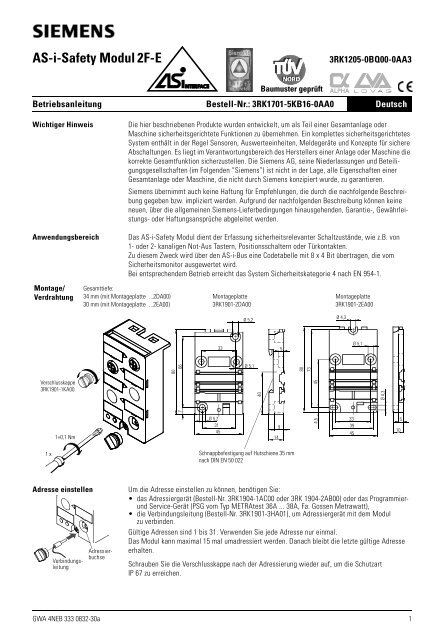
<strong>AS</strong>-i-<strong>Safety</strong> Modul 2F-E3RK1205-0BQ00-0AA3Baumuster geprüftBetriebsanleitung Bestell-Nr.: 3RK1701-5KB16-0AA0 DeutschWichtiger HinweisDie hier beschriebenen Produkte wurden entwickelt, um als Teil einer Gesamtanlage oderMaschine sicherheitsgerichtete Funktionen zu übernehmen. Ein komplettes sicherheitsgerichtetesSystem enthält in der Regel Sensoren, Auswerteeinheiten, Meldegeräte und Konzepte für sichereAbschaltungen. Es liegt im Verantwortungsbereich des Herstellers einer Anlage oder Maschine diekorrekte Gesamtfunktion sicherzustellen. Die <strong>Siemens</strong> AG, seine Niederlassungen und Beteiligungsgesellschaften(im Folgenden “<strong>Siemens</strong>”) ist nicht in der Lage, alle Eigenschaften einerGesamtanlage oder Maschine, die nicht durch <strong>Siemens</strong> konzipiert wurde, zu garantieren.<strong>Siemens</strong> übernimmt auch keine Haftung für Empfehlungen, die durch die nachfolgende Beschreibunggegeben bzw. impliziert werden. Aufgrund der nachfolgenden Beschreibung können keineneuen, über die allgemeinen <strong>Siemens</strong>-Lieferbedingungen hinausgehenden, Garantie-, Gewährleistungs-oder Haftungsansprüche abgeleitet werden.AnwendungsbereichMontage/VerdrahtungDas <strong>AS</strong>-i-<strong>Safety</strong> Modul dient der Erfassung sicherheitsrelevanter Schaltzustände, wie z.B. von1- oder 2- kanaligen Not-Aus Tastern, Positionsschaltern oder Türkontakten.Zu diesem Zweck wird über den <strong>AS</strong>-i-Bus eine Codetabelle mit 8 x 4 Bit übertragen, die vomSicherheitsmonitor ausgewertet wird.Bei entsprechendem Betrieb erreicht das System Sicherheitskategorie 4 nach EN 954-1.Gesamttiefe:34 mm (mit Montageplatte ...2DA00) Montageplatte Montageplatte30 mm (mit Montageplatte ...2EA00) 3RK1901-2DA00 3RK1901-2EA00Ø 5,2Ø 4,3335Ø 5,18066Ø 5,18073Verschlusskappe3RK1901-1KA0040457Ø 4,31+0,1 NmØ 5,231459144,53339451051 xSchnappbefestigung auf Hutschiene 35 mmnach DIN EN 50 022Adresse einstellenAdressierbuchseVerbindungsleitungUm die Adresse einstellen zu können, benötigen Sie:• das Adressiergerät (Bestell-Nr. 3RK1904-1AC00 oder 3RK 1904-2AB00) oder das ProgrammierundService-Gerät (PSG vom Typ METRAtest 36A ... 38A, Fa. Gossen Metrawatt),• die Verbindungsleitung (Bestell-Nr. 3RK1901-3HA01), um Adressiergerät mit dem Modulzu verbinden.Gültige Adressen sind 1 bis 31. Verwenden Sie jede Adresse nur einmal.Das Modul kann maximal 15 mal umadressiert werden. Danach bleibt die letzte gültige Adresseerhalten.Schrauben Sie die Verschlusskappe nach der Adressierung wieder auf, um die SchutzartIP 67 zu erreichen.GWA 4NEB 333 0832-30a 1
InbetriebnahmeLogische Zuordnung1234ADDRStatus-LEDs<strong>AS</strong>-iFAULT21 35 4Führen Sie folgende Schritte aus, um das Modul in Betrieb zu nehmen:Schritt Vorgehensweise1 Stellen Sie die Adresse ein, wenn Sie vor der Montage adressieren wollen.2 <strong>AS</strong>-i Leitung so einlegen, dass die breite Seite oben ist (Profilnase der Leitung beliebig).3 Hängen Sie das Modul in die Montageplatte ein und verschrauben Sie es.4 Stellen Sie die Adresse ein, wenn Sie Schritt 1 nicht ausgeführt haben.5 Schließen Sie die Schaltglieder an den M12-Buchsen an.Folgende Tabelle zeigt die logische Zuordnung für 3RK1205-0BQ00-0AA3:BuchseBelegung / Datenblätter / Funktion1 Pin 1 und Pin 2: beeinflusst die Bits D0 und D1 = Kanal 1,Pin 3 und Pin 4: beeinflusst die Bits D2 und D3 = Kanal 2, Pin 5 nicht belegt.2 Pin 1 und Pin 2: beeinflusst die Bits D2 und D3 = Kanal 2, Pin 5 nicht belegt.3 nicht belegt4 nicht belegt• Soll an das Modul nur ein einkanaliger Schalter angeschlossen werden, so ist dieser anKanal 1 anzuschliessen. Der 2. Kanal muss gebrückt werden. Dies kann durch eine Drahtbrückezwischen PIN 3 und PIN 4 an Buchse 1 geschehen oder mit dem M12-Stecker 3RK1901-1AA00an Buchse 2.• Es ist Pin 3 der Buchse 1 mit Pin 1 der Buchse 2 sowie Pin 4 der Buchse 1 mit Pin 2 derBuchse 2 verbunden! Werden beide Buchsenpaare belegt erfolgt eine Verknüpfung derEingänge!Folgende Tabelle zeigt die Status-LEDs mit dem jeweiligen Betriebszustand:<strong>AS</strong>-i / FAULTBetriebszustandgrünKommunikation in OrdnungAusKeine Spannung an <strong>AS</strong>-Interface-Chiprot permanent Kommunikation ausgefallenrot/gelb blinkend Slave hat Adresse "0"Hinweise• Decken Sie nicht benutzte M12-Buchsen mit Verschlusskappen ab, um die Schutzart IP 67 zuerreichen.• Die Schutzart IP 67 wird nach Befestigung des Moduls auf der Montageplatte mit eingelegterLeitung erreicht.• Die Buchsen 3 und 4 sind nicht zu öffnen.• Die PE - Steckfahne (unten) ist nicht belegt.• In einem, vom Sicherheitsmonitor überwachten, <strong>AS</strong>-i-Strang darf jede Codetabelle nur einmalvorkommen.Technische DatenElektrische Daten gemäß E/A-Konfiguration (Hex) 0<strong>AS</strong>-i-SpezifikationID-Code (Hex)BID1-Code (Hex)FID2-Code (Hex)FGesamtstromaufnahme I ≤ 45 mAVerpolschutzjaEingänge Low-Signalbereich Kontakt offenHigh-Signalbereich Kontakt geschlossenI in dynamisch (I peak ≥ 5 mA)Mechanische Daten Schutzart IP 67 (mit Montageplatte 3RK1901-2.A00)Gewichtca. 100 gAbmessungen in mm (H x B x T)80 x 45 x 30 oder 34 (je nach Montageplatte)Temperaturbereich Bemessungstemperatur T u 25 °CUmgebungstemperatur T a -25 °C bis 85 °CLagertemperatur T s -40 °C bis 85 °CWerkstoff Gehäuse PBT (Crastin)DichtungTPE (Thermoplast K) im GehäuseNBR für O-Ring in den Buchsen M12Schraube, ScheibeEdelstahl V2AGewindebuchse (Montageplatte) Edelstahl V2A2 3RK1701-5KB16-0AA0
<strong>AS</strong>-i-<strong>Safety</strong> Module 2F-E3RK1205-0BQ00-0AA3Operating Instructions Order No.: 3RK1701-5KB16-0AA0 EnglishImportant NoticeThe products described herein are designed to be components of a customized machinery safetyorientedcontrol system. A complete safety-oriented system may include safety sensors, evaluators,actuators and signaling components. It is the responsibility of each company to conduct itsown evalution of the effectiveness of the safety system by trained individuals. <strong>Siemens</strong> AG, itssubsidiaries and affiliates (collectively "<strong>Siemens</strong>") are not in a position to evaluate all of the characteristicsof a given machine or product.<strong>Siemens</strong> accepts no liability for any recommendation that may be implied or stated herein. The warrantycontained in the contract of sale by <strong>Siemens</strong> is the sole warranty of <strong>Siemens</strong>. Any statementscontained herein do not create new warranties or modify existing ones.ApplicationsInstallation/WiringThe <strong>AS</strong>-i safety module detects switching states that affect safety, such as the positions of1-channel or 2-channel emergency stop pushbuttons, position switches or door contacts.For this purpose, a code table with 8x4 bits, evaluated by the safety monitor, is transferred overthe <strong>AS</strong>-i bus.When operated properly, the system attains <strong>Safety</strong> Category 4 as per EN 954-1.Total depth:34 mm (with mounting plate ...2DA00) Mounting plate Mounting plate30 mm (with mounting plate ...2EA00) 3RK1901-2DA00 3RK1901-2EA00Ø 5,2Ø 4,3335Ø 5,18066Ø 5,18073Screw plug3RK1901-1KA0074045Ø 4,31+0,1 NmØ 5,231459144,53339451051 xSnapped on to standard mounting rail(35 mm) to DIN EN 50 022Setting addressConnectingcableAddresssocketTo be able to set the address, you require the following:• the addressing devices (Order No. 3RK1904-1AC00 or 3RK1904-2AB00) or the programming andservicing unit (PSG of type METRAtest 36A...38A, Gossen Metrawatt),• the connecting cable (Order No. 3RK1901-3HA01) for connecting addressing deviceto module.Valid addresses are 1 to 31. Use each address once only.The module can be re-addressed up to 15 times. After this, the last valid address is preserved.After addressing has been completed, re-attach the screw plug to obtain degree of protection IP 67.3
CommissioningLogic assignments1234ADDRStatus-LEDs<strong>AS</strong>-iFAULT21 35 4To start up the module, carry out the following steps:Step Procedure1 Set the address if you want to carry out addressing prior to installation.2 Arrange the <strong>AS</strong>-i cable so that the wide edge is at the top (profile lug as desired).3 Engage the module in the mounting plate and secure with screws.4 Set the address if you have not carried out step 1.5 Connect the switching elements to the M12 sockets.The following table shows the logic assignments for 3RK1205-0BQ00-0AA3:SocketPin Assignments / Data Sheets / Function1 Pin 1 and pin 2: acts on bits D0 and D1 = channel 1,Pin 3 and pin 4: acts on bits D2 and D3 = channel 2, pin 5 not used.2 Pin 1 and pin 2: acts on bits D2 and D3 = channel 2, pin 5 not used.3 Not used4 Not used• If only one one-channel switch is to be connected, this must be assigned to channel 1. The 2ndchannel must be jumpered. This can be performed via a wire jumper between PIN 3 and PIN 4 atsocket 1 or with the M12 plug 3RK1901-1AA00 at socket 2.• Pin 3 of socket 1 is connected with pin 1 of socket 2, and pin 4 of socket 1 is connected withpin 2 of socket 2! If both pairs of sockets are in use, the inputs are linked!The following table shows the status - LEDs and their operating states:<strong>AS</strong>-i / FAULTOperating stategreenCommunication OKOffNo voltage present at <strong>AS</strong>-Interface-Chipred permanent Communication failedred/yellow flashing Slave has address "0"Notes • Cover unused M12 sockets with screw plugs to obtain degree of protection IP 67.• Degree of protection IP 67 is obtained after the module is fixed on the mounting plate withcable inserted.• Sockets 3 and 4 are not to be opened.• The PE plug tag (below) is not in use.• Each code table may occur only once in one <strong>AS</strong>-i line connected to the safety monitor.Technical dataElectrical data as per <strong>AS</strong>-i I/O configuration (hex) 0specificationID code (hex)BID1-Code (hex)FID2-Code (hex)FTotal current drain I ≤ 45 mAReverse polarity protectionyesInputs Low sigal range contact openHigh signal range contact closedI in dynamic (I peak ≥ 5 mA)Mechanical data Degree of protection IP 67 (with mounting plate 3RK1901-2.A00)Weightapprox. 100 gDimensions in mm (h x w x d)80 x 45 x 30 or 34 (according to mounting plate)Temperature range Rated temperature T u 25 °CAmbient temperature T a - 25 °C to 85 °CStorage temperature T s - 40 °C to 85 °CMaterial Casing PBT (Crastin)GasketTPE (thermoplastic K) in the casingNBR for O-ring in the M12 socketsScrew, washerStainless steel V2AThreaded socket (Mounting plate) Stainless steel V2A4 3RK1701-5KB16-0AA0
Module de sécurité <strong>AS</strong>-i 2F-E3RK1205-0BQ00-0AA3Instructions de service N° de référence : 3RK1701-5KB16-0AA0 FrançaisRemarque importanteLes produits décrits dans cette notice ont été développés pour assurer des fonctions de sécuritéen tant qu’éléments d’une installation complète ou d’une machine. Un système de sécurité completcomporte en règle générale des capteurs, des unités de traitement, des appareils de signalisationet des concepts de mise en sécurité. Il incombe au concepteur/constructeur de l’installationou de la machine d’assurer le fonctionnement correct de l’ensemble. <strong>Siemens</strong> AG, ses succursaleset ses participations (désignées ci-après par “<strong>Siemens</strong>”) ne sont pas en mesure de garantir toutesles propriétés d’une installation complète ou d’une machine qui n’a pas été conçue par <strong>Siemens</strong>.<strong>Siemens</strong> dégage toute responsabilité pour les recommandations données dans la descriptionci-dessous ou qui peuvent en être déduites. La description ci-dessous ne peut pas être invoquéepour faire valoir des revendications au titre de la garantie ou de la responsabilité, qui dépasseraientles clauses des conditions générales de livraison de <strong>Siemens</strong>.Domaine d'emploi Le module de sécurité <strong>AS</strong>-i sert à l’acquisition d’états de contacts de sécurité, par ex. :de boutons-poussoirs d’arrêt d’urgence, d’interrupteurs de position ou de contacts de portes à 1 ou2 canaux.A cet effet, une table de code de 8x4 bits est transmise sur le bus <strong>AS</strong>-i qui est exploitée par lemoniteur de sécurité.Si le système est exploité en conséquence, il satisfait à la catégorie de sécurité 4 selon EN 954-1.Montage/CâblageProfondeur totale :34 mm (avec embase ...2DA00) Embase Embase30 mm (avec embase ...2EA00) 3RK1901-2DA00 3RK1901-2EA00Ø 5,2Ø 4,3335Ø 5,18066Ø 5,18073Bouchon3RK1901-1KA0040745Ø 4,31+0,1 NmØ 5,231459144,53339451051 xFixation par encliquetage sur profilé chapeau35 mm selon DIN EN 50 022Réglage de l’adresse Pour régler l’adresse, il vous faut :• la console d'adressage (réf. 3RK1904-1AC00 ou 3RK1904-2AB00) ou la console de programmationet maintenance (PSG du type METRAtest 36A...38A, sté. Gossen Metrawatt),• le câble de liaison (réf. 3RK1901-3HA01) entre la console d’adressage et le module.Adresses valables : 1 à 31. Chaque adresse ne doit intervenir qu'une seule fois.L’adresse du module peut être changée au maximum 15 fois ; le module conserve ensuite la dernièreadresse valable réglée.Câble deliaisonPriseadressageAprès l’adressage, revissez le bouchon pour rétablir le degré de protection IP 67.5
Mise en service Effectuez les opérations suivantes pour mettre le module compact en service :Etape Opération1 Réglez l'adresse si vous désirez le faire avant le montage.2 Posez le câble <strong>AS</strong>-i de manière que le côté large se trouve en haut (nez profilé ducâble indifférent).3 Accrochez le module à l’embase et fixez-le en serrant la vis.4 Si vous n'avez pas effectué l'étape 1, réglez l’adresse du module.5 Raccordez les contacts aux connecteur M12.Affectation logique Le tableau suivant donne l'affectation logique 3RK1205-0BQ00-0AA3 :1ConnecteurAffectation / Fiches techniques / Fonction221 Contacts 1 et 2 : agissent sur les bits D0 et D1 = canal 1,3 1 3Contacts 3 et 4 : agissent sur les bits D2 et D3 = canal 2, contact 5 non affecté4 5 42 Contacts 1 et 2 : agissent sur les bits D2 et D3 = canal 2, contact 5 non affectéADDR3 non affecté4 non affecté• Si l’on envisage de raccorder au module un seul interrupteur à 1 canal, il faudra le raccorder aucanal 1. Le 2ème canal doit être ponté. Ceci peut se faire au moyen d’un fil entre les contacts 3et 4 du connecteur 1 ou au moyen de la fiche M12 3RK1901-1AA00 sur le connecteur 2.• Le contact 3 du connecteur 1 est relié au contact 1 du connecteur 2, et la contact 4 duconnecteur 1 au contact 2 du connecteur 2 ! Si les deux connecteurs sont utilisés, les états desentrées sont combinés suivant une fonction logique !LED d’état Le tableau suivant donne la signification des LED de signalisation d’état :<strong>AS</strong>-iFAULT<strong>AS</strong>-i / FAULTEtatverteCommunication O.K.éteinte<strong>AS</strong>IC <strong>AS</strong>-Interface non alimentérouge feu fixeCommunication perturbéerouge/jaune clignotant Esclave avec adresse "0"Remarques• Obturez les connecteurs M12 inutilisés avec des bouchons pour obtenir le degré deprotection IP 67.• La protection IP 67 est obtenue après fixation du module sur l’embase avec câble en place.• Les connecteurs 3 et 4 ne peuvent pas être ouverts.• La languette PE (en bas) n’est pas utilisée.• Chaque table de code ne doit intervenir qu’une fois dans chaque ligne <strong>AS</strong>-i surveillée par lemoniteur de sécurité.Caractér. techniquesCaract. électriques selon Configuration E/S (hexa) 0spécification <strong>AS</strong>-iCode ID (hexa)BCode ID1 (hexa)FCode ID2 (hexa)IFConsommation totale I ≤ 45 mAProt. contre invers. de polaritéouiEntrées Etat logique "bas" contact ouvertEtat logique "haut" contact ferméI in dynamique (I crête ≥ 5 mA)CaractéristiquesDegré de protectionIP 67 (avec embase 3RK1901-2.A00)mécaniquesPoidsenv. 100 gDimensions (H x L x P)80 x 45 x 30 ou 34 mm (suivant l’embase)Plage de température Température assignée T u 25 °CTempérature ambiante T a - 25 °C à 85 °CTempérature de stockage T s - 40 °C à 85 °CMatières Boîtier PBT (Crastin)Joint d’étanchéitéTPE (thermoplastique K) dans le boîtierNBR pour joint torique dans les prises M12Vis, rondelleacier inoxydable V2ADouille filetée (Embase)acier inoxydable V2A6 3RK1701-5KB16-0AA0
Modulo <strong>AS</strong>-i-<strong>Safety</strong> 2F-E3RK1205-0BQ00-0AA3Istruzioni di servizio N. di ordinazione: 3RK1701-5KB16-0AA0 ItalianoAvviso importante:Campo d’impiegoI prodotti qui descritti sono stati concepiti per svolgere funzioni rilevanti per la sicurezza in interiimpianti. Un sistema di sicurezza completo prevede normalmente sensori, disposititvi di segnalazione,apparecchiature e unità di valutazione e dispositivi per disinserzioni sicure. È compito delcostruttore di macchine garantire il funzionamento sicuro dell’impianto o della macchina. La<strong>Siemens</strong> AG, le sue filiali e consociate (qui di seguito "<strong>Siemens</strong>") non sono in grado di garantiretutte le caratteristiche di un impianto o una macchina non ideati da <strong>Siemens</strong>.<strong>Siemens</strong> declina ogni responsabilità per raccomandazioni contenute nella presente descrizione.Non è possibile in nome della presente documentazione arrrogare diritti di garanzia e/o responsabilitàche vadano oltre quanto contenuto nelle condizioni generali di vendita e fornitura.Il modulo <strong>AS</strong>-i-<strong>Safety</strong> serve per rilevare stati di commutazione relativi alla sicurezza, quali ad es. ipulsanti di emergenza a 1 o 2 canali, gli interruttori di posizione e i contatti di porte.A tale scopo viene tramessa sul bus <strong>AS</strong>-i una tabella di codici con 8x4 bit che viene valutata dalmonitor di sicurezza.Se il funzionamento è corretto il sistema ottempera alla categoria di sicurezza 4 sec. EN 954-1.Montaggio/CablaggioProfondità complessiva:34 mm (con piastra di montaggio ...2DA00) Piastra di montaggio Piastra di montaggio30 mm (con piastra di montaggio ...2EA00) 3RK1901-2DA00 3RK1901-2EA00Ø 5,2Ø 4,3335Ø 5,18066Ø 5,18073Capsula di chiusura3RK1901-1KA0040745Ø 4,31+0,1 NmØ 5,231459144,53339451051 xFissaggio a scatto su profilato ad omegada 35 mm sec. DIN EN 50 022IndirizzamentoCavo dicollegamentoConnettoredi indirizzamentoPer poter impostare l’indirizzo, sono necessari:• l’apparecchio di indirizzamento (n. di ordinazione 3RK1904-1AC00 oppure 3RK1904-2AB00)oppure il dispositivo di programmazione e di service (PSG del tipo METRAtest 36A...38A,Ditta. Gossen Metrawatt).• il cavo di collegamento (n. di ordinazione 3RK1901-3HA01) per collegare l’apparecchio di indirizzamentoal modulo.Gli indirizzi validi sono compresi tra 1 e 31. Utilizzare ciascun indirizzo una sola volta.L’indirizzo del modulo può essere cambiato al massimo 15 volte. Dopo di che rimane valido l’ultimoindirizzo impostato.Dopo l’indirizzamento riavvitare la capsula di chiusura per ottenere il grado di protezione IP 67.7
Messa in servizioAssegnazione logica1234ADDRLED di stato<strong>AS</strong>-iFAULT21 35 4Procedere come segue per mettere in servizio il modulo compatto:Passo Procedura1 Impostare l’indirizzo se si desidera indirizzare il modulo prima del montaggio.2 Posizionare il cavo <strong>AS</strong>-i in modo tale che la parte inferiore sia rivolta verso l’alto(introdurre il cavo profilato a piacere).3 Inserire il modulo nella piastra di montaggio ed avvitarlo.4 Impostare l’indirizzo se si è saltato il passo 1.5 Collegare i contatti ai connettori M12.La tabella seguente riporta l’assegnazione logica 3RK1205-0BQ00-0AA3:ConnettoreAssegnazione / fogli dei dati / funzione1 Pin 1 e pin 2: agiscono sui bit D0 e D1 = canale 1,Pin 3 e pin 4: agiscono sui bit D2 e D3 = canale 2, pin 5 non assegnato.2 Pin 1 e pin 2: agiscono sui bit D2 e D3 = canale 2, Pin 5 non assegnato.3 non assegnato4 non assegnato• Se al modulo viene collegato un solo interruttore a un canale, quest’ultimo va collegato alcanale 1. Il secondo canale va ponticellato mediante ponte a filo tra il PIN 3 e il PIN 4 sullaspina 1 o mediante connettore M12 3RK1901-1AA00 sulla spina 2.• Il pin 3 del connettore 1 è collegato al pin 1 del connettore 2; il pin 4 del connettore 1 è collegatoal pin 2 del connettore 2. Se vengono occupate entrambe le coppie di connettori leuscite risultano cominate!La tabella seguente riporta i LED di stato con il relativo stato di funzionamento:<strong>AS</strong>-i / FAULTStato di funzionamentoverdeCommunicazione regolareOffManca tensione su chip <strong>AS</strong>-Interfacerosso fissoCommunicazione interrotarosso/giallo intermittente Slave ha indirizzo"0"AvvertenzeDati tecniciDati elettrici secondospecifica <strong>AS</strong>-i• Coprire i connettori M12 non utilizzati con capsule di chiusura in moda da ottenere il grado diprotezione IP 67.• Il grado di protezione IP 67 si raggiunge fissando il modulo sulla piastra di montaggio con cavoinserito.• Le spine 3 e 4 non vanno aperte.• La linguetta PE (in basso) non è assegnata.• In un segmento <strong>AS</strong>-i sorvegliato dal monitor di sicurezza, ogni singola tabella dei codici puòessere presente una volta sola.Configurazione I/O (esa) 0Codice ID (esa)BCodice ID1 (esa)FCodice ID2 (esa)FAssorbimento di corrente totale I ≤ 45 mAProtez. da inversione polaritàsiIngressi Campo dei segnali low contatto apertoCampo dei segnali high contatto chiusoI in dinamico (I peak ≥ 5 mA)Dati meccanici Grado di protezione IP 67 (con piastra di montaggio 3RK1901-2.A00)Pesoca. 100 gDimensioni in mm (H x L x P)80 x 45 x 30 opp. 34 (a sec della piastra di montag.)Campo di temperatura Temperatura nominale T u 25 °CTemperatura ambiente T a - 25 °C ... 85 °CTemperatura di magazzinaggio T s - 40 °C ... 85 °CMateriale Custodia PBT (Crastin)GuarnizioneTPE (Thermoplast K) nella custodiaNBR per anello ad O nelle spine M12Vite, rondellaacciaio inox V2ABoccola filettata (Piastra di montaggio) acciaio inox V2ATechnical Support: Tel: ++49 (0) 9131-7-43833 (8°° - 17°° MEZ) Fax: ++49 (0) 9131-7-42899E-mail: NST.technical-support@erl7.siemens.de Internet: www.ad.siemens.de/supportTechnische Änderungen vorbehalten.Subject to change without prior notice.© <strong>Siemens</strong> AG 2000Bestell-Nr./Order No.: 3RK1701-5KB16-0AA0Printed in the Federal Republic of Germany