Manual DMT 8000(24-11-11) - Fagor Electrónica
Manual DMT 8000(24-11-11) - Fagor Electrónica
Manual DMT 8000(24-11-11) - Fagor Electrónica

Create successful ePaper yourself
Turn your PDF publications into a flip-book with our unique Google optimized e-Paper software.
3. OUTPUT SERVICES: Servicios a la salida3.1. Pass-Through: Modo transparente o conselección / edición de servicios.(seleccionar con ❏ ▲ ❏▼ y pulsar OK ).3.2. List of Services: lista de servicios.● Pulsar para ver la lista.● Pulsar ❏ ▲ ❏▼ para seleccionar el servicio.● Pulsar para entrar en los parámetros del servicio.– Un signo "+" seguido del nombre del servicio, indica queese servicio esta en el Multiplex de salida.– Un signo " * " delante del nombre indica sevicio encriptado.3.2.1. Active: activa el servicio en el MUX de salida.(seleccionar con ❏ ▲ ❏▼ y pulsar OK ).3.2.2. LCN: permite asignar un LCN (Logical Channel Number)entre 1 y 1023 a los servicios presentes en la salida(seleccionar con ❏ ▲ ❏ ▼ y pulsar OK ; “0000” equivalea NO LCN).3.2.3. Program Number: informa del PN del servicio.3.3. Output MUX ( %): informa del % total ocupadodel MUX de salida.- No es recomendable trabajar con el MUX BW de salidasuperior al 80% ya que los servicios varían su Bitrate durantela transmisión. (Output MUX BW > 92% : LED de estado enambar).❏ ▼ ❏ ▼3.4. Clear All?: borra todos los servicios seleccionadosen la salida DVB-T. (pulsar OK ).3.5. Read Services?: lee los servicios de la entrada ASI.(pulsar OK ).4. PSI EDIT: Permite la configuración de la NITde salida.4.1. NIT Mode: Pass-Through /LOCAL. Si se selecciona"Local", se permite modificar los siguientes parámetros.4.2. Network Name: permite dar un nombre a la red.4.3. Network ID: identificador de red: 0 ÷ 65535(dar el mismo valor que el Orig Network ID).4.4. TS ID: identificador de Transport Stream: 0 ÷ 65535.Algunos receptores de DVB-T necesitan que el TS IDsea diferente por cada módulo.4.5. Orig. Net. ID: identificador de la Red Origen:0 ÷ 65535. Configuración por país (ver tabla 3).5. MEMORY: Memoria- Memorización automática: después de 30 minutosdesde la última tecla pulsada, los datos actuales sememorizarán en el STT-CI <strong>8000</strong>.5.1. Save Configuration: memoriza la programación actual.5.2. Restore Configuration: permite recuperar laconfiguración memorizada en el equipo.5.3. Save Configuration, Device to UCF 300:Guarda la configuración memorizada con un nombreidentificador en una de las 26 memorias de la Unidad deControl UCF 300.5.4. Load Configuration, UCF 300 to Device:recupera los datos de una memoria del UCF 300 condatos grabados de un <strong>DMT</strong> para ser clonados en otro<strong>DMT</strong> <strong>8000</strong>.■ AJUSTE DE NIVELES RF1. Extraer el puente coaxial de la Salida de CanalRF (8) del modulo 1º junto a la Fuente de alimentación.2. Ajustar el nivel de salida a 75 dBμV, medianteUCF 300 (Ver punto 1.2 Programación).3. Conectar de nuevo el puente coaxial de 75 Ω.4. Midiendo en la salida del Amplificador SHA ó SAC,regular los niveles de los demás módulos, para lograrecualizarlos al nivel del módulo 1º ya regulado.5. Regular la ganancia del Amplificador, teniendo en cuentael nivel máximo de su salida y la reducción en funcióndel número de canales de la instalación, según Tabla 1.Tab. 1Nº de canalesCOFDM2 4 5 6 8 16 <strong>24</strong> 32 64Reducción nivelmax. de salida (dB)3 6 7 8 9 12 16 15 18■ FUNCIONES DE LOS LEDS● Led de estado:● Color Verde: OK.● Color Ambar: Problemas con la señal.– Servicios no encontrados en la entrada.– BW de salida excedido > 92%.– Output RF: OFF.● Color Rojo: Equipo averiado● Led de Comunicaciones: Ambar: a la espera de datos.■ PREGUNTAS FRECUENTES● ¿Cuántos programas caben en un Canal de RF,COFDM, UHF, 8 MHz?La capacidad del canal de salida se mide en MBsy hay una relación directa de:● Modulación: QPSK < 16 QAM < 64 QAM● Code Rate FEC:1/2 < 2/3 < 3/4 < 5/6 < 7/8● Intervalo de guarda IG: 1/4 < 1/8 < 1/16 < 1/32(máxima capacidad en negrita).● TDT España: 19,91MBs MUX tip. COFDM.●5DVB-T (8MHz)Bitrate (Mbps)Modulación Code Rate Tu = 1/4 Tu = 1/8 Tu = 1/16 Tu = 1/321/2 4,98 5,53 5,85 6,032/3 6,64 7,37 7,81 8,04QPSK 3/4 7,46 8,29 8,78 9,055/6 8,29 9,22 9,76 10,057/8 8,71 9,68 10,25 10,561/2 9,95 <strong>11</strong>,06 <strong>11</strong>,71 12,062/3 13,27 14,75 15,61 16,0916 QAM 3/4 14,93 16,59 17,56 18,105/6 16,59 18,43 19,52 20,<strong>11</strong>7/8 17,42 19,35 20,49 21,<strong>11</strong>1/2 14,93 16,59 17,56 18,102/3 19,91 22,12 23,42 <strong>24</strong>,1364 QAM 3/4 22,39 <strong>24</strong>,88 26,35 27,145/6 <strong>24</strong>,88 27,65 29,27 30,167/8 26,13 29,03 30,74 31,67El número de programas depende de la cantidadde información que lleva cada uno.E
PROBLEMAS Y CAUSAS POSIBLESEEfectoLED Status; verdeLED Status: AmbarLED Status: RojoLED Comm: AmbarMensajes en UCF 300PROGRAM MISSINGTABLES NOT FOUNDOUT BW EXCEEDEDHW FAILLURELCN REPEATEDCausaOK.No hay Tablas en la entradaServicio de salida ya no existeen el transponderNo hay salida de RFImagen TV se pixelaFallo de hadwareEsperando datos de controlServicio no encontradoMala señal de entradaImagen TV se pixelaFallo de hadwareLCN repetidosAcciónRevisar conexión y cable de entrada DVB-ASILeer la lista de servicios OUTPUT SERVICES; Read Services ycomprobar si ha desaparecido algún programa de la listaChequear si OUTPUT RF está activado: “YES"Comprobar si Output Mux BW(%) es inferior al 92%.(OUTPUT SERVICES)Apagar y encenderRevisar Bus de Comunicación entre módulos y unidadMCU <strong>8000</strong>. Situación normal sin MCU <strong>8000</strong>Leer servicios para actualizar la lista. Read Servicesen OUTPUT SERVICESRevisar conexión y cable de entrada DVB-ASIComprobar si Output Mux BW(%) es inferior al 92%.(OUTPUT SERVICES)Apagar y encenderVerificar la repetición de los LCN de los servicios activos6
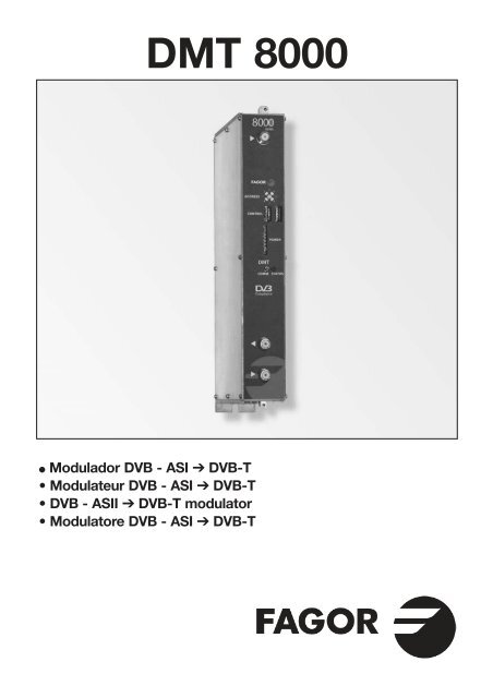
F■ DESCRIPTION● Modulateur de signal DVB-ASI en DVB-T.Accepte les signaux d'entrée MPEG-2 TS Packet ouBurst format et délivre le signal modulé en COFDM.Le signal en format DVB-ASI avec programmation numériqueest converti à la bande RF entre 50.5 et 858 MHz moduléeen DVB-T. Gère les signaux MPEG-2 o MPEG-4 enpermettant d’effectuant une sélection des programmesdélivrés à sa sortie.■ INSTALLATION ET MISE EN MARCHE❏ ❏ ▼ ▼❏ ▲ ❏ ▼❏ ▲❏ ▼❏ ▲❏ ▲- Les connexions et déconnexions des modules doiventse faire avec l’alimentation débranchée.● Relier la prise de terre du châssis à la terre de l’installationde l’antenne.● Fixer les modules sur le châssis dans l’ordre indiquésur l’exemple d’application (voir page 3) : alimentation àdroite et amplificateur à gauche de l’ensemble.● Relier les Sorties de Canal RF (8) à l’aide du pont coaxialF-F (Ref. 83814) et charger avec 75 Ω la sortie libre dumodule 1, à côté de l’alimentation.● Connecter le Bus d’Alimentation BA 807 réf. 83807 entreles modules (5) et l’alimentation SPS.● Branchez les signaux ASI sur l’entrées (1) avec câblecoaxial 75 Ω.● Brancher l’alimentation sur le secteur.■ TEMPERATURE DE FONCTIONNEMENT● Les modules doivent être refroidis pour fonctionnercorrectement. Il est donc nécessaire que les modulessoient assemblés dans le coffret ventilé (Réf 83806) ouquand on fait le montage en rack 19’’ d’utiliser l’unité deventilation (réf 83801) Quand il y a pas beaucoup demodules à installer, on peut monter le VNT 800. Voir fig.1■ PROGRAMMATION DES MODULESLes modules permettent ces types de programmation:● Par l’unité de contrôle UCF 300 (Réf 85<strong>11</strong>5), en mode local,en suivant les pas montrés dans ce manuel.● Par PC, en mode local. Pour ça, il est nécessaire d’avoirun module MCU <strong>8000</strong> et l’interface « <strong>8000</strong> series »dans le PC.■ UCF 300 : FONCTIONS DES TOUCHES● Les touches ❏ ▲ ❏▼ permettent le déplacement verticaldans le menu.a) Dans le menu de programmation, elles servent àchoisir la fonction à programmer.b) Dans une fonction, elles servent à sélectionner unparamètre.c) Dans un paramètre programmable, elles servervent àmodifier sa valeur.● Les touches permettent le déplacement horizontaldans le menu de programmation, ex.:Fonction paramètre valeur.● La touche avance vers la droite.● La touche quitter sans modifier la valeur : escape● La touche OK valide la donnée programmée.■ INDICATIONS SUR L’AFFICHEUR● L’unité de contrôle UCF 300 dispose de deux files decaractères alphanumériques. Le mode d’affichage desdonnées et le schéma de programmation de la page xxnous guident dans le processus :● Quand les caractères sont tous en majuscules etsur la file supérieure, nous sommes dans l’une des5 fonctions.● Quand les données apparaissent sur les deux filesde l’écran, nous voyons le paramètre à régler.● La flèche droite indique comment modifier la valeurdu paramètre.● Un petit carré clignotant indique que nous pouvonsmodifier la valeur du paramètre avec les touches❏ ▲ ❏▼ (pour confirmer, presser la touche OK ).● Un signe “+” suivi du nom du service indique que ceservice se trouve dans le Multiplex de sortie.● Un signe “ * ” devant le nom indique programmed'accès conditionnel.■ PROGRAMMATION AVEC UCF 300● Connecter la UCF 300 au module voulu ; après quelquessecondes, l’équipement présente le modèle dont il s’agit.● Appuyez sur la touche pour entrer dans le menu desfonctions de programmation standard (accès au menuétendu en appuyant OK pendant 3 secondes).1. RF OUTPUT2. DVB-T OUTPUT (menu étendu)3. OUTPUT SERVICES (menu étendu)4. PSI EDIT (menu étendu)5. MEMORY● La pression des touches ❏ ▲ ❏▼ nous déplace parmiles fonctions.● La pression la touche donne accès aux paramètresde la fonction recherchée.Voir diagramme de promammation pag. 10 e <strong>11</strong>.❏ ▼❏ ▼1. RF OUTPUT: Sortie de RF1.1. Out Freq (MHz): Fréquence de Sortie:50,5 ÷ 858 MHz.1.2. Out Level (dBμV): Niveau de sortie: 65 ÷ 80 dBμV.1.3. Ouput RF: Dés/active la sortie de RF.2. DVB-T OUTPUT: Sortie DVB-T2.1. DVB T Mode: 2K, 8K.2.2. QAM Mode: QPSK, 16 QAM, 64 QAM.2.3. Code Rate: FEC 1/2, 2/3, 3/4, 5/6, 7/8.2.4. Guard Interval: 1/4, 1/8, 1/16, 1/32.2.5. Bandwidth (MHz): 6, 7, 8 MHz.2.6. IQ mode: normal, Invertido.7
F3. OUTPUT SERVICES: Services en sortie3.1. Pass-Through: mode transparent ou de sélection/edition de les services.(sélectionner avec ❏ ▲ ❏▼ et presser OK ).3.2. List of Services: liste des services.● Presser pour voir la liste.● Presser ❏ ▲ ❏▼ pour sélectionner le service.● Appuyez sur pour entrer les paramètres de service.– Une signe "+" suivi du nom du service, indique quele service est dans le multiplex de sortie.– Une signe " * " devant le nom indique sevice crypté.3.2.1. Active: activer le service dans le MUX de sortie.(sélectionner avec ❏ ▲ ❏▼ et presser OK ).3.2.2. LCN: permet d’allouer un numéro (LCN) entre 1 et1023 à cette chaîne en sortie (sélectionner le numéroavec les touches ❏ ▲ ❏▼ et appuyer sur OK .0000 veut dire pas d’allocation de numéro particulier(pas de LCN).3.2.3. Program Number: PN du service.❏ ▼ ❏ ▼3.3. Output MUX BW: % total occupé du MUX de sortie.- Il est déconseillé de travailler avec le MUX BW de sortiesupérieur à 80% car les services peuvent augmenter leurBitrate pendant la transmission. (Sortie MUX BW > 92%:LED d'état dans l'orange).3.4. Clear all: effacer tous les services sélectionnés surla sortie DVB-T. (presser OK ).3.5. Read Services: lire les services du transpondeur.(presser OK ).4. PSI EDIT: permet de configurer les tables NIT en sortie.4.1. NIT Mode: Pass-Through / Sélection locale.Si la sélection locale est choisie, permet de modifier lesparamètres décrits ci-après.4.2. Network Name: permet de donner un nom au réseau.4.3. Network ID: donner la même valeur que Orig. Net.ID.4.4. TS ID: certains récepteurs ont besoin d’un TS IDdifférent pour chaque module (valeur entre 0 et 65535).4.5. Orig. Net. ID: Original Network Identifier, identifiantspécifique par pays (voir table 3).5. MEMORY- Sauvegarde automatique : au bout de 30 minutessans presser de touche, les données actuelles sontenregistrées sur le STT <strong>8000</strong>.5.1. Save Configuration: enregistrer la programmationactuelle.5.2. Restore Configuration: permet de récupérer leparamétrage sauvegardé sur l’équipement.5.3. Save Configuration, Device to UCF 300:permet de conserver le paramétrage sauvegardéavec un identificateur dans l’une des 26 mémoiresde l'unitée de control <strong>Fagor</strong> UCF 300.5.4. Load Configuration, UCF 300 to Device:récupère les données d’une mémoire de l’UCF 300avec les données enregistrées sur un <strong>DMT</strong> pour êtreclonées sur un autre <strong>DMT</strong> <strong>8000</strong>.■ RÉGLAGE DES NIVEAUX RF1. Extraire le pont coaxial de la Sortie de Canal RF (8)du module 1 avec l’alimentation.2. Régler le niveau de sortie sur 75 dBμV,à l’aide de l’UCF 300 (Voir chapitre 2 Programmation).3. Replacer le pont coaxial de 75 Ω.4. En mesurant sur la sortie de l’amplificateur SHA ouSAC, régler les niveaux des autres modules, pour leslisser sur le niveau du module 1 déjà réglé.5. Régler le gain de l’amplificateur, en tant compte duniveau maximum de sa sortie et de la réduction enfonction du nombre de canaux de l’installation, selonla Table 1.Tab. 1Nombre de canauxCOFDM2 4 5 6 8 16 <strong>24</strong> 32 64Facteur de réductionsur niveau máxsortie (dB)3 6 7 8 9 12 16 15 18■ FONCTIONS DES LED● LED d’état :● Couleur Verte: OK● Couleur Orange: Problèmes de signal– Programme introuvable.– BW de sortie dépassé > 92 %.– Sortié RF: OFF● Couleur Rouge: équipement en panne● LED de communication : orange: en attente de données.■ QUESTIONS FRÉQUENTES :● Combien de programmes accepte un Canal de RF,COFDM, UHF, 8 MHz ?La capacité du canal de sortie se mesure en MB et il existeun rapport direct de :● Modulation: QPSK < 16 QAM < 64 QAM● Code Rate FEC:1/2 < 2/3 < 3/4 < 5/6 < 7/8● Intervalle de garde IG: 1/4 < 1/8 < 1/16 < 1/32(capacité maximale en gras).● TDT España: 19,91MBs MUX tip. COFDM.DVB-T (8MHz)Bitrate (Mbps)Modulation Code Rate Tu = 1/4 Tu = 1/8 Tu = 1/16 Tu = 1/321/2 4,98 5,53 5,85 6,032/3 6,64 7,37 7,81 8,04QPSK 3/4 7,46 8,29 8,78 9,055/6 8,29 9,22 9,76 10,057/8 8,71 9,68 10,25 10,561/2 9,95 <strong>11</strong>,06 <strong>11</strong>,71 12,062/3 13,27 14,75 15,61 16,0916 QAM 3/4 14,93 16,59 17,56 18,105/6 16,59 18,43 19,52 20,<strong>11</strong>7/8 17,42 19,35 20,49 21,<strong>11</strong>1/2 14,93 16,59 17,56 18,102/3 19,91 22,12 23,42 <strong>24</strong>,1364 QAM 3/4 22,39 <strong>24</strong>,88 26,35 27,145/6 <strong>24</strong>,88 27,65 29,27 30,167/8 26,13 29,03 30,74 31,67● Le nombre de programmes dépend de la quantitéd’information que comporte chacun.8
FPROBLÈMES ET CAUSES POSIBLESEffetLED Statu: vertLED Statu: OrangeLED Statu: RougeLED Comm: OrangeMESSAGES en DisplayUCF 300PROGRAM MISSINGTABLES NOT FOUNDOUT BW EXCEEDEDHW FAILLURELCN REPEATEDCauseOK.Il n’y a pas de tables dans l’entréeLe service de sortie n’existeplus dans le transpondeurIl n’y a pas de sortie RFPixelation de l’image TVDéfaut hardwareEn attente de données decontrôleService non trouvéMauvais signal à l’entréePixelation de l’image TVDéfaut hardwareLCN répétésActionVérifiez la connexion et le câble d’entrée DVB-ASILire la liste des services OUTPUT SERVICES et vérifier si unprogramme a disparu de la liste.Vérifier si SORTIE RF est activé : « YES »Vérifier si BW Mux sortie(%) est inférieur à 92%.(OUTPUT SERVICES)Débrancher et rebrancherVérifier bus de communication entre les modules etl’MCU (situation d’habitude en cas d’absence d’MCU)Lire la liste des services OUTPUT SERVICES etvérifier si un programme a disparu de la listeVérifiez la connexion et le câble d’entrée DVB-ASIVérifier si BW Mux sortie(%) est inférieur à 92%.(OUTPUT SERVICES)Débrancher et rebrancherVérifier la répétition des LCN des services activés9
<strong>DMT</strong> <strong>8000</strong>❏ ▲❏ ▼ OK❏ ▲❏ ▲❏ ▲ ❏ ▼❏ ▲❏ ▲ ❏ ▼❏ ▼❏ ▲❏ ▼ OK❏ ▲❏ ▼ OK❏ ▲❏ ▲❏ ▲❏ ▼❏ ▲ ❏ ▼❏ ▲ ❏ ▼❏ ▼ ❏ ▲ ❏ ▼ ❏ ▲❏ ▼ ❏ ▲❏ ▲❏ ▼ OK❏ ▲❏ ▼ OK❏ ▲ ❏ ▼❏ ▲❏ ▲❏ ▼❏ ▲ ❏ ▼❏ ▼ ❏ ▲❏ ▼ ❏ ▲❏ ▲❏ ▼ OK❏ ▲❏ ▲❏ ▼❏ ▲❏ ▲ ❏ ▼ OK❏ ▼➞■ UCF 300 Diagrama de programación Programming diagramDiagramme de programmation Diagrama di programmazioneRF OUTPUTPress OK for3 seconds toaccess➞(Extended menu)Out Freq (MHz)474.000 ➞Out Level (dBµV)7500 ➞❏ ▼ ❏ ▲Output RFYES ➞Out Freq (MHz)50,5 ÷ 858Out Level (dBµV)65 ÷ 80Output RFYES / NOFactory default valuesRF Output Output ServicesOutput Frequency: 474,000 MHz Pass Through “YES”Output Level: 75 dBμVOutput RF: YesDVB-T Output PSI EDITDVB T Mode: 8 K NIT Mode: LocalQAM Mode: 64 QAM Network Name: FAGOR <strong>DMT</strong>Code Rate: 7/8 Network ID: 08442Guard Interval: 1/32 TS ID: 00001Bandwidth: 8 MHz Orig. Net. ID: 08442IQ Mode: NormalDVB-T OUTPUT➞DVB-T Mode8K ➞QAM Mode64 QAM ➞Code Rate7/8 ➞DVB-T Mode2K / 8KQAM ModeQPSK, 16, 64 QAMCode Rate1/2, 2/3, 3/4, 5/6, 7/8❏ ▲ ❏ ▼❏ ▼ ❏ ▲Guard Interval1/32 ➞❏ ▼ ❏ ▲Bandwidth (MHz)8 ➞❏ ▼ ❏ ▲IQ ModeNORMAL ➞Guard Interval1/4, 1/8, 1/16, 1/32Bandwidth (MHz)6, 7, 8IQ ModeNormal / Inverted❏ ▲❏ ▼ OK❏ ▲❏ ▼ OK10
(Extended menu)❏ ▲❏ ▼ OK❏ ▲❏ ▲ ❏ ▼❏ ▲ ❏ ▲❏ ▼❏ ▲ ❏ ▲ ❏ ▲ ❏ ▼❏ ▲ ❏ ▲ ❏ ▲❏ ▲ ❏ ▼❏ ▲ ❏ ▲ ❏ ▲ ❏ ▲ ❏ ▲ ❏ ▼❏ ▲ ❏ ▲ ❏ ▼❏ ▲ ❏ ▼OUTPUT SERVICES➞OK❏ ▲ ❏ ▼❏ ▲PSI EDITMEMORYOK❏ ▲ ❏ ▼❏ ▲ ❏ ▼Pass-ThroughYES ➞Pass-ThroughYES / NO ➞❏ ▲❏ ▲▼❏ ▼ ❏ ▲ ❏ ▼ ❏ ▲❏ ▼ ❏ ▲❏ ▲▼(Available only Pass-❏ ▼ ❏ ▲(Available only Pass-Trough “NO”) List of ServicesList of ServicesActiveActive + Encorder 1 ➞+ Encorder 1 ➞YES ➞YES / NO▼❏ ▼ ❏ ▲❏ ▼❏ ▼ ❏ ▲Output Mux BW(%)LCNLCN(Information)❏ ▲▼47.50010 ➞0÷999▼Trough “NO”)Clear All?Program NumberOKPress OK257(Information)❏ ▼ ❏ ▲ ❏ ▼ ❏ ▲(Available only Pass-Trough “NO”)Read Services?Press OKOK(Extended menu)NIT ModeNIT Mode ❏ ▼ ❏ ▲Local ➞Pass -Through/Local▼➞❏ ▼ ❏ ▲Network NameNetwork Name❏ ▲ FAGOR <strong>DMT</strong> ➞FAGOR <strong>DMT</strong> ▼ OKNetwork IDNetwork ID❏ ▲ 08442 ➞08442 ▼ OKSave Config.Press OKOK❏ ▼ ❏ ▲➞❏ ▼ ❏ ▲TS IDTS ID ❏ ▲00001 ➞00001▼Restore Config.❏ ▼ ❏ ▲OKPress OKOrig. Net. IDOrig. Net. ID❏❏ ▼ ❏ ▲08442 ➞08442▼ OKSave Config.REGISTER NUM:1❏ ▲ ▼ OKDevice ➞UCF300➞<strong>DMT</strong>:REG1❏ ▼ ❏ ▲OK❏ ▲ ❏ ▼❏ ▲ ❏ ▼❏ ▲ ❏ ▼OK❏ ▲ ❏ ▼❏ ▲ ❏ ▼Load Config.UCF300 ➞Device➞REGISTER NUM:1<strong>DMT</strong>:REG1❏ ▲❏ ▼ OKOnly shows the registers ofthe same type of device<strong>11</strong>
UK■ DESCRIPTION● DVB-ASI modulator in DVB-T. Admits MPEG TS inputsignals in Packet or Burst format and deliveries modulatedsignal in COFDM. DVB-ASI signal with digital programmingis converted to the RF band between 50.5 and 858 MHzmodulated in DVB-T. Handles MPEG-2 or MPEG-4 signalsenabling selection of programs delivered on output.■ INSTALLATION AND START-UP- The power sources must be disconnected fromthe mains before connecting or disconnecting themodule.● Connect the earth connection of the frame to the earthconnection of the antenna installation.● Fix the modules to the frame in the order shown in theapplication example (see page 3), with the power sourceon the right and the amplifier on the left of the unit.● Join the RF channel outputs (8) via the F-F coaxial bridge(Ref. 83814), and load the free output of module 1 with75 Ω, beside the power source.● Connect the Supply bus BA 807 ref. 83807 between themodules (5) and the SPS.● Connect the ASI output cable to the correspondinginputs (1) with 75 Ω coaxial cables.● Connect the power source to the mains.■ WORKING TEMPERATURE● The modules have to be refreshed for their correctoperationt. It's recommended to install the modules inthe housing with fan (Ref 83806) or, when installing ona 19" rack, to use the Rack ventilation Unit (ref 83801)When there are few modules to install, it's possible touse the fan VNT 800 on the wall frame (fig N 1).■ MODULES PROGRAMMATIONThe modules can be programmed:● Through the UCF 300 Control Unit (Ref 85<strong>11</strong>5) in localmode, following the steps explained in this manual.● Through a PC in local mode. In this case, it's necessaryto have a MCU <strong>8000</strong> unit and the "<strong>8000</strong> series" interfaceinstalled in the PC.■ UCF 300: BUTTONS' FUNCTIONS● The buttons ❏ ▲ ❏▼ are for vertical menu scrolling.a) On the programming menu they are for selecting thefunction to be programmed.b) A parameter can be selected within a function.c) A parameter setting can be modified within aprogrammable parameter.● The buttons are for horizontal scrolling through theprogramming menu, e.g.:Function parameter value.● The button is for moving right.● The button is for exiting without changing the setting:escape.❏ ▲ ❏ ▼❏ ▼ ❏ ▲❏ ▲❏ ▼❏ ▲❏ ▼● The OK button is for validating the data item programmed.■ DISPLAY INDICATIONS● The UCF 300 control unit has two rows of alphanumericalcharacters. The data display mode and programmingdiagram on page xx are a guide to this process:● If the characters are all upper case and on the upperrow, this indicates that one of the 5 functions has beenentered.● If data appear on two rows of the display, theparameter to be adjusted is being displayed.● The right arrow shows how to enter to change theparameter setting.● A flashing box indicates that the parameter setting canbe modified using the ❏ ▲ ❏ ▼(press the OK button to validate).● A “+” sign followed by the name of the service indicatesthat this service is in the output multiplex.● A “ * ” sign before the name indicates an encryptedservice.■ PROGRAMMING with UCF 300● Connect the UCF 300 to the desired module. After afew seconds, the unit will show the model in question.● Press the button to enter the standard menu(access to extended menu pressing OK during 3 sec)1. RF OUTPUT2. DVB-T OUTPUT (extended menu)3. OUTPUT SERVICES (extended menu)4. PSI EDIT (extended menu)5. MEMORY● Press the ❏ ▲ ❏▼ button to scroll through the functions.● Press the button to enter the parameters of thedesired function.See programming diagram on page 10 and <strong>11</strong>.❏ ▼❏ ▼1. RF OUTPUT: RF output1.1. Out Frequency (MHz):: 50,5 ÷ 858 MHz.1.2. Out Level (dBμV): 65 ÷ 80 dBμV.1.3. Out RF: Enables/disables the RF output.2. DVB-T OUTPUT: DVB-T output2.1. DVB T Mode: 2K, 8K.2.2. QAM Mode: QPSK, 16 QAM, 64 QAM.2.3. Code Rate: FEC 1/2, 2/3, 3/4, 5/6, 7/8.2.4. Guard Interval: 1/4, 1/8, 1/16, 1/32.2.5. Bandwidth: 6, 7, 8 MHz.2.6. IQ mode: normal, Inverted.12
3. OUTPUT SERVICES3.1. Pass-Through: Transparent mode or withselection / services edition (select with ❏ ▲ ❏ ▼ andpress OK ).3.2. List of Services: list of services.● Press to view the list.● Press ❏ ▲ ❏▼ to select the service.● Press to enter the service parameters.– A "+" sign followed by the name of the service indicatesthat this service is in the output multiplex.– A " * " sign before the name indicates an encrypted service.3.2.1. Active: enables the service on output MUX(use ❏ ▲ ❏▼ to select and press OK ).3.2.2. LCN: Allows assigning a LCN (Logical ChannelNumber) between 1 and 1023 to the services at theoutput (select with ❏ ▲ ❏▼ and press OK ; “0000”stands for NO LCN).3.2.3. Program Number: indicates the service PN.3.3. Output MUX BW: indicates the total % of the outputMUX occupied.❏ ▼ ❏ ▼- It is not recommendable to work with the output MUX BWabove 80%, as the services may increase their bitrate duringtransmission. (Output MUX BW > 92%: Status LED in yellow).3.4. Clear all: clears all the services selected in the DVB-Toutput. (Press OK ).3.5. Read Services: It reads the ASI input services(Press OK ).4. PSI EDIT: Allows the Output’s NIT configuration.4.1. NIT Mode: Pass-Through / LOCAL selection. If local ischosen, allows modifying the following parameters.4.2. Network Name: Allows living a name to the network.4.3. Network ID: Network identificator: 0 ÷ 65535 (give thesame value as the Orig.Net.ID).4.4. TS ID: Some receivers need a different TS ID for everymemorised module (value between 0 and 65535).4.5. Orig. Net. ID: Original Network Identifier by Country(see table 3).5. MEMORY- Automatic save: 30 minutes after the last button ispressed, the current data will be stored in the <strong>DMT</strong> <strong>8000</strong>.5.1. Save Configuration: Stores current programming.5.2. Restore Configuration: Enables the configurationstored in the unit to be recovered.5.3. Save Configuration, Device to UCF 300:enables the configuration stored to be saved with anidentifying name in one of the 26 memories of theUCF 300.5.4. Load Configuration, UCF 300 to Device:recovers the data in one of the UCF 300’s memorieswith data recorded from an <strong>DMT</strong> for cloning on another<strong>DMT</strong> <strong>8000</strong>.■ RF LEVEL ADJUSTMENT1. Remove the coaxial bridge from the RF channeloutput (8) of module 1 beside the power source.2. Adjust the output level to 75 dBμV via UCF 300(see point 2 Programming).3. Connect the 75 Ω axial bridge again.4. Taking the measurement at the SHA or SAC amplifieroutput, adjust the levels of the other modules so thatthey are equalised to the level of module 1,which has already been adjusted.5. Adjust the amplifier gain, taking into account itsmaximum output level and the reduction accordingto the number of the channels in the installation,as shown in Table 1.Tab. 1Number ofchannels COFDM2 4 5 6 8 16 <strong>24</strong> 32 64Reduction of themaximum output 3 6 7 8 9 12 16 15 18level (dB)■ LED FUNCTIONS● Status LED:● Green color: Tuner tuned● Yellow color: Signal problems– Program not found.– Exceeded output BW > 92%.– Out RF: OFF.● Red color: Unit failure● Communication LED: Yelow: waiting for data.■ FAQs:● How many programs fit on an RF, COFDM, UHF,8 MHz channel?The channel’s output capacity is measured in MBs andthere is a direct relationship between the following:● Modulation: QPSK < 16 QAM < 64 QAM● Code Rate FEC:1/2 < 2/3 < 3/4 < 5/6 < 7/8● Save interval IG: 1/4 < 1/8 < 1/16 < 1/32(maximum capacity shown in bold).●DVB-T (8MHz)Bitrate (Mbps)Modulation Code Rate Tu = 1/4 Tu = 1/8 Tu = 1/16 Tu = 1/321/2 4,98 5,53 5,85 6,032/3 6,64 7,37 7,81 8,04QPSK 3/4 7,46 8,29 8,78 9,055/6 8,29 9,22 9,76 10,057/8 8,71 9,68 10,25 10,561/2 9,95 <strong>11</strong>,06 <strong>11</strong>,71 12,062/3 13,27 14,75 15,61 16,0916 QAM 3/4 14,93 16,59 17,56 18,105/6 16,59 18,43 19,52 20,<strong>11</strong>7/8 17,42 19,35 20,49 21,<strong>11</strong>1/2 14,93 16,59 17,56 18,102/3 19,91 22,12 23,42 <strong>24</strong>,1364 QAM 3/4 22,39 <strong>24</strong>,88 26,35 27,145/6 <strong>24</strong>,88 27,65 29,27 30,167/8 26,13 29,03 30,74 31,67The number of programs depends on the amountof information contained in each one.UK13
TROUBLESHOOTINGUKEffect“Status” LED colour: Green“Status” LED colour: Orange“Status” LED colour: Red“Comm” LED colour: OrangeMessages on UCF 300displayPROGRAM MISSINGTABLES NOT FOUNDOUT BW EXCEEDEDHW FAILLURELCN REPEATEDCauseOK.There are no tables in the inputOutput Service disappearedfrom transponderNo RF outputImage pixilationHardware failureWaiting control dataService not foundDefective Input SignalImage pixilationHardware failureLCN repeatedActionCheck input cable and DVB - ASI conectionsCheck OUTPUT SERVICES list; Read Services and check if anyprogram disappearedCheck if OUTPUT RF is “YES"Check if Output Mux BW(%) is lower than 92%.(OUTPUT SERVICES)Switch OFF and ON againCheck Communication Bus between Modules andMCU <strong>8000</strong>. OK if there is no MCU <strong>8000</strong> unitRead Services in OUTPUT SERVICESCheck input cable and DVB - ASI conectionsCheck if Output Mux BW(%) is lower than 92%.(OUTPUT SERVICES)Switch OFF and ON againCheck LCN repetition on active services14
I■ DESCRIZIONE● Modulatore di segnale DVB-ASI in DVB-T.Supporta segnali MPEG-2 TS in formato pacchettoo Burst all’uscita segnali codulati in COFDM.I segnali in formato DVB-ASI con programmazione digitale èconvertita in frequenza alla banda tra 50.5 e 858 MHzmodulata in DVB-T. Gestisce segnali MPEG-2 o MPEG-4,consentendo una selezione dei programmi consegnatiall’uscita.■ INSTALLAZIONE E AVVIO❏ ▼ ❏ ▼❏ ▼ ❏ ▲❏ ▲❏ ▼❏ ▲❏ ▲- I collegamenti e scollegamenti dei moduli devonoessere fati con il alimentatore spento.● Collegare la presa di terra del telaio alla messa a terradell’impianto dell’antenna.● Fissare i moduli al telaio nell’ordine indicato nell’esempiodi applicazione (v. pag. 3). Alimentatore a destra eamplificatore a sinistra del gruppo.● Unire le Uscite del canale RF (8) mediante il ponticellocoassiale F-F (Ref. 83814), e caricare a 75 Ω l'uscita liberadel modulo 1 (vicino all'alimentatore).● Collegare il Bus di alimentazione BA 807 rif. 83807 frai moduli (5) e il alimentatore SPS.● Collegare i cavi di uscita ASI negli ingressi (1) con cavocoassiale di 75 Ω.● Collegare l'alimentatore alla rete elettrica.■ TEMPERATURA DI FUNZIONAMENTO● I moduli devono essere rafredati per il suo corretttofunzionamento. Per quello è necessario che i modulisiano assemblati nell'armadio ventilato (Cod. 83806)oppure utilizare le ventole (Rif: 83801) quando ilmontaggio sia a rack 19". Per pocchi moduli a panelloparete si può utilizare il VNT 800 (Fig.1.).■ PROGRAMMAZIONE DEI MODULII moduli possono essere programmat● Tramite il programmatore UCF 300 (Cod.85<strong>11</strong>5) seguendola procedura descritta in questo manuale.● Tramite PC con il modulo MCU <strong>8000</strong> (Cod.85<strong>11</strong>0)e il software "<strong>8000</strong> series".■ UCF 300: FUNZIONI DEI TASTI● I tasti ❏ ▲ ❏▼ permettono di spostarsi verticalmente lungoil menù.a) Nel menù di programmazione permettono diselezionare la funzione da programmare.b) All’interno di una funzione permettono di selezionareun parametro.c) All’interno di un parametro programmabile,permettono di modificarne il valore.● I tasti permettono di spostarsi orizzontalmentenel menù di programmazione, ad es.:Funzione parametro valore.● Il tasto avanza verso destra.● Il tasto esce senza modificare il valore: escape● Il tasto OK convalida il dato programmato.■ INDICAZIONI SUL DISPLAY● L’unità di controllo UCF 300 dispone di due file di caratterialfanumerici; la modalità di visualizzazione dei dati assiemeal diagramma di programmazione della pagina xx ciguidano nel processo:● Quando i caratteri sono tutti in maiuscole e nella filasuperiore, indicano che siamo in una delle 5 funzioni.● Quando compaiono dei dati su due file del display:viene visualizzato il parametro da regolare.● La freccia destra indica come entrare a modificare ilvalore del parametro.●Un quadratino che lampeggia indica che si puòmodificare il valore del parametro con i tasti ❏ ▲ ❏ ▼(per convalidare premere il tasto OK ).● Un segno “+” seguito dal nome del servizio indicache tale servizio è nel Multiplex di uscita.● Un segno “ * ” davanti al nome indica sevizio criptato.■ PROGRAMMAZIONE con UCF 300● Collegare la UCF 300 al modulo desiderato; dopoqualche secondo, l’apparecchio presenta il modellodi cui si tratta.● Premendo il tasto si accede alle funzioni menu❏ ▼standard (menu esteso premendo OK durante 3 secondi):1. RF OUTPUT2. DVB-T OUTPUT (menu esteso)3. OUTPUT SERVICES (menu esteso)4. PSI EDIT (menu esteso)5. MEMORYPremendo i tasti ❏ ▲ ❏●▼ ci si sposta fra le funzioni.● Premendo i tasto si entra nei parametri dellafunzione desiderata.Vedi diagramma di programmazione a pagina 10 e <strong>11</strong>.❏▼1. RF OUTPUT: Uscita RF1.1. Out Freq (MHz): Frequenza di uscita:50,5 ÷ 858 MHz.1.2. Out Level (dBuV): Livello di uscita: 65 ÷ 80 dBμV.1.3. Output RF: Disattiva l’uscita RF.2. DVB-T OUTPUT: Uscita DVB-T2.1. DVB T Mode: 2K, 8K.2.2. QAM Mode: QPSK, 16 QAM, 64 QAM.2.3. Code Rate: FEC 1/2, 2/3, 3/4, 5/6, 7/8.2.4. Guard Interval: 1/4, 1/8, 1/16, 1/32.2.5. Bandwidth: 6, 7, 8 MHz.2.6. IQ mode: Normale, invertito.15
I3. OUTPUT SERVICES3.1. Pass-Through: Modo trasparente oppure conscelta (edizione dei servizi).(selezionare con ❏ ▲ ❏▼ e premere OK ).3.2. List of Services: elenco dei servizi.● Premere per visualizzare l’elenco.● Premere ❏ ▲ ❏▼ per selezionare il servizio.● Premere per accedere ai parametri del servizio.– Un simbolo "+" seguito dal nome del servizio, indica chequel servizio è nel multiplex d’uscita.– Un simbolo " * " davanti del nome indica che il servizio è criptato.3.3.1. Active: attiva o disattiva il servizio(selezionare con ❏ ▲ ❏▼ e premere OK ).3.2.2. LCN: Permette assegnare un LCN (Logical ChannelNumber) tra 1 e 1023 a tutti i servizi che sono all’uscita(scegliere con ❏ ▲ ❏ ▼ e premere OK , 0000 significache non c’è LCN).3.2.3. Program Number: informazioni sul PN del servizio.3.3. Output MUX BW: Informazioni sulla % totaleoccupata dal MUX di uscita.❏ ▼ ❏ ▼- Si racommanda non lavorare con il MUX BW sopra 80%,perche i Bit Rate dei servizi variano durante la trassmisione.Se l'Output Mux BW > 92% il led di stato c'è gialo:3.4. Clear all?: Cancella tutti i servizi selezionati nell’uscitaDVB-T. “premere OK ”.3.5. Read Services?: lettura dei servizi del transponder.“premere OK ”.4. PSI EDIT: Permette la programmazione dellaNIT d’uscita.4.1. NIT Mode: Scelta Pass-Through / LOCAL. Se la sceltaè LOCAL, ci lascia modificare I seguenti parametri.4.2. Network Name: Permette dare un nome alla rete.4.3. Network ID: ID della rete (dare lo stesso valore cheall’Orig Net ID).4.4. TS ID: Alcuni ricevitori DVB-T hanno bisogno che ilTS ID si diverso per ogni modulo memorizzato (valorevariabile tra 0 e 65535).4.5. Orig. Net. ID: ID della rete di Origine per paese,secondo la tabella 3.5. MEMORY- Memorizzazione automatica: dopo 30 minuti daquando è stato premuto l’ultimo tasto, i dati attualivengono memorizzati nel <strong>DMT</strong> <strong>8000</strong>.5.1. Save Configuration: Memorizza la programmazioneattuale.5.2. Restore Configuration: Permette di recuperare laconfigurazione memorizzata nel sistema.5.3. Save Configuration, Device to UCF 300:consente di salvare la configurazione memorizzatacon un nome di identificazione in una delle 26 memoriedella unità di controllo <strong>Fagor</strong> UCF 300.5.4. Load Configuration, UCF 300 to Device:recupera i dati di una memoria dell’ UCF 300 con datiregistrati di un <strong>DMT</strong> per clonarli in un altro <strong>DMT</strong> <strong>8000</strong>.■ REGOLAZIONE DEI LIVELLI RF1. Estrarre il ponte coassiale dell’Uscita del canale RF (8)del modulo 1º insieme alla Fonte di alimentazione.2. Impostare il livello di uscita a 75 dBμV, medianteUCF 300 (v. punto 1.2 Programmazione).3. Collegare di nuovo il ponte coassiale da 75 Ω.4. Misurando all’uscita dell’Amplificatore SHA o SAC,regolare i livelli degli altri moduli, per equalizzarli allivello del modulo 1º già regolato.5. Regolare il coefficiente di amplificazione, tenendo contodel livello massimo dell’uscita dell’Amplificatore e dellariduzione in funzione del numero di canali dell’impianto,come da Tabella 1.Tab. 1Nº di canaliCOFDM2 4 5 6 8 16 <strong>24</strong> 32 64Riduzione sul livellod’uscita massi. (dB)3 6 7 8 9 12 16 15 18■ FUNZIONI DEI LED● Led di stato:● Colore verde: Tuner sincronizzato● Colore giallo: Errore nel segnale– Programma non trovato all'ingresso.– Largeza di banda di uscita superato > 92%.– Out RF: OFF.● Colore rosso: Sistema guasto● Led di comunicazione: giallo, in attesa dei dati.■ DOMANDE FREQUENTI:● ¿Quanti programmi contiene un canale di RF, COFDM,UHF, 8 MHz?La capacità del canale di uscita si misura in MB e c’è unrapporto diretto di:● Modulazione: QPSK < 16 QAM < 64 QAM● Code Rate FEC: 1/2 < 2/3 < 3/4 < 5/6 < 7/8● Intervallo di guardia IG: 1/4 < 1/8 < 1/16 < 1/32(massima capacità in neretto).DVB-T (8MHz)Bitrate (Mbps)Modulazione Code Rate Tu = 1/4 Tu = 1/8 Tu = 1/16 Tu = 1/321/2 4,98 5,53 5,85 6,032/3 6,64 7,37 7,81 8,04QPSK 3/4 7,46 8,29 8,78 9,055/6 8,29 9,22 9,76 10,057/8 8,71 9,68 10,25 10,561/2 9,95 <strong>11</strong>,06 <strong>11</strong>,71 12,062/3 13,27 14,75 15,61 16,0916 QAM 3/4 14,93 16,59 17,56 18,105/6 16,59 18,43 19,52 20,<strong>11</strong>7/8 17,42 19,35 20,49 21,<strong>11</strong>1/2 14,93 16,59 17,56 18,102/3 19,91 22,12 23,42 <strong>24</strong>,1364 QAM 3/4 22,39 <strong>24</strong>,88 26,35 27,145/6 <strong>24</strong>,88 27,65 29,27 30,167/8 26,13 29,03 30,74 31,67●Il numero di programmi dipende dalla quantitádi informazioni contenuta in ciascuno di essi.16
IPROBLEME E SOLUZIONEProblemaLED Status; verdeLED Status: GialloLED Status: RossoLED Comm: GialloMESSAGGInell’UCF 300PROGRAM MISSINGTABLES NOT FOUNDOUT BW EXCEEDEDHW FAILLURELCN REPEATEDCausaOK.Non ci sono tabelle all’ingressoIl servizio scelto non c’è più neltransponderNon c’è segnale di RF all’uscitaL‘ immaggine TV si pixelaErrore di HardwareIn attesa dei dati di controlloServizio non trovatoPessimo segnale all’ingressoL‘ immaggine TV si pixelaErrore di HardwareLCN ripetutiAzioneVerificare il collegamento e il cavo all’ingresso DVB-ASILeggere l'elenco di OUTPUT SERVICES; Leggeretutti i servizi e vedere se qualcuno è scomparsoVerificare se OUTPUT RF è attivo: “YES"Verificare se Output Mux BW(%) è sotto dal 92%.(OUTPUT SERVICES)Spengere e riaccendereVerificare il bus di communicazione tra i moduli e l’unità dicontrollo MCU <strong>8000</strong>. Situazione normale se non c’è la MCULeggere i servizi per aggiornare l’elenco.Read Services in OUTPUT SERVICESVerificare il collegamento e il cavo all’ingresso DVB-ASIVerificare se Output Mux BW(%) è sotto dal 92%.(OUTPUT SERVICES)Spengere e riaccendereVerificare se i LCN dei servizi attivi sono ritpetuti17
Tab. 2BANDCHANNELCHANNEL BANDWIDTHCENTRALFREQ.MHz MHzVHF BI 2 47...54 50,53 54...61 57,54 61...68 64,5VHF Bs S1 104...<strong>11</strong>1 107,5(low) S2 <strong>11</strong>1...<strong>11</strong>8 <strong>11</strong>4,5S3 <strong>11</strong>8...125 121,5S4 125...132 128,5S5 132...139 135,5S6 139...146 142,5S7 146...153 149,5S8 153...160 156,5S9 160...167 163,5S10 167...174 170,5VHF BIII 5 174...181 177,56 181...188 184,57 188...195 121,58 195...202 198,59 202...209 205,510 209...216 212,5<strong>11</strong> 216...223 219,512 223...230 226,5VHF Bs S<strong>11</strong> 230...237 233,5(high) S12 237...<strong>24</strong>4 <strong>24</strong>0,5S13 <strong>24</strong>4...251 <strong>24</strong>7,5S14 251...258 254,5S15 258...265 261,5S16 265...272 268,5S17 272...279 275,5S18 279...286 282,5S19 286...293 289,5S20 293...300 296,5VHF S21 302...310 306Hyperband S22 310...318 314S23 318...326 322S<strong>24</strong> 326...334 330S25 334...342 338S26 342...350 346S27 350...358 354S28 358...366 362S29 366...374 370S30 374...382 378S31 382...390 386S32 390...398 394S33 398...406 402S34 406...414 410S35 414...422 418S36 422...430 426S37 430...438 434S38 438...446 442S39 446...454 450S40 454...462 458S41 462...470 466BANDCHANNELCHANNEL BANDWIDTHCENTRALFREQ.MHz MHzUHF 21 470...478 47422 478...486 48223 486...494 490<strong>24</strong> 494...502 49825 502...510 50626 510...518 51427 518...526 52228 526...534 53029 534...542 53830 542...550 54631 550...558 55432 558...566 56233 566...574 57034 574...582 57835 582...590 58636 590...598 59437 598...606 60238 606...614 61039 614...622 61840 622...630 62641 630...638 63442 638...646 64<strong>24</strong>3 646...654 65044 654...662 65845 662...670 66646 670...678 67447 678...686 68<strong>24</strong>8 686...694 69049 694...702 69850 702...710 70651 710...718 71452 718...726 72253 726...734 73054 734...742 73855 742...750 74656 750...758 75457 758...766 76258 766...774 77059 774...782 77860 782...790 78661 790...798 79462 798...806 80263 806...814 81064 814...822 81865 822...830 82666 830...838 83467 838...846 84268 846...854 85069 854...862 858Tab. 3 Orig.Net.ID/CountryOrig.Net.ID COUNTRY08212 Andorra08228 Australia08232 Austria08<strong>24</strong>8 Belgium08362 Colombia08383 Croatia08395 Czech Republic08400 Denmark08425 Estonia08438 Finland08442 France08468 Germany08903 Hungary08552 Indonesia08564 Ireland08568 Israel08572 Italia08620 Latvia08720 Netherland08746 New Zealand08770 Norway08800 Philippines08808 Poland08904 Portugal08894 Singapore08895 Slovak Republic08897 Slovenia08902 South Africa08916 Spain08945 Sweden08948 Switzerland08350 Taiwan09018 UK18
JJK / FAGOR. <strong>DMT</strong> <strong>8000</strong> / 4 I / <strong>11</strong>-<strong>11</strong> • 02175134<strong>Fagor</strong> <strong>Electrónica</strong>, S.Coop.San Andrés, s/n. P. O. Box 33E-20500 Mondragón (Spain)Tel. +34 943 712 526Fax +34 943 712 893E-mail: rf.sales@fagorelectronica.eswww.fagorelectronica.com