Manual STT CI 8000(27-9-11) - Fagor Electrónica
Manual STT CI 8000(27-9-11) - Fagor Electrónica
Manual STT CI 8000(27-9-11) - Fagor Electrónica
- No tags were found...

Create successful ePaper yourself
Turn your PDF publications into a flip-book with our unique Google optimized e-Paper software.
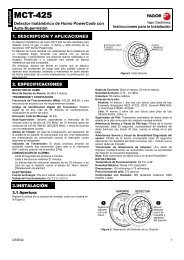
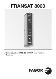
UK■ DESCRIPTION● DVB-S and DVB-S2 signal transmodulator in DVB-CFree-to-Air (SCT <strong>8000</strong>) and with Conditionnal AccessDVB-<strong>CI</strong> (SCT-<strong>CI</strong> <strong>8000</strong>). Admits QPSK or 8PSK inputsignals and modulated signal delivery in QAM.Allows satellite programs to be viewed with DVB-C receivers.1st IF SAT signal with digital programming is convertedto the RF band between 50.5 and 858 MHz modulatedin DVB-C. Handles MPEG-2 or MPEG-4 signals enablingselection of programs delivered on output.■ INSTALLATION AND START-UP- The power sources must be disconnected fromthe mains before connecting or disconnecting themodule.● Insert the CAM into the module ( look position N 10in the CONTROLS schema) before placing the moduleon the frame (SCT-<strong>CI</strong> <strong>8000</strong>).● Connect the earth connection of the frame to the earthconnection of the antenna installation.● Fix the modules to the frame in the order shown in theapplication example (see Fig.2), with the power sourceon the right and the amplifier on the left of the unit.● Make the signal distribution of the antenna(s) via the F-Fcoaxial bridge (Ref. 83814) and load the free output(s)with 75 Ω (Ref. 840<strong>11</strong>).● Join the RF channel outputs (Fig.1, 8) via the F-F coaxialbridge, and load the free output of module 1 with 75 Ω,beside the power source.● Connect the Supply bus BA 807 ref. 83807 between themodules (Fig.1, 5) and the SPS.● Connect the antenna drop cables to the correspondinginputs (Fig.1, 1).● Connect the power source to the mains.■ WORKING TEMPERATURE● The modules have to be refreshed for their correctoperationt. It's recommended to install the modules inthe housing with fan (Ref 83806) or, when installing ona 19" rack, to use the Rack ventilation Unit (ref 83801)When there are few modules to install, it's possible touse the fan VNT 800 on the wall frame (Fig.1, 5).■ MODULES PROGRAMMATIONThe modules can be programmed:● Through the UCF 300 Control Unit (Ref 85<strong>11</strong>5) in localmode, following the steps explained in this manual.● Through a PC in local mode. In this case, it's necessaryto have a MCU <strong>8000</strong> unit and the "<strong>8000</strong> series" interfaceinstalled in the PC.■ UCF 300: BUTTONS' FUNCTIONS● The buttons ❏ ▲ ❏▼ are for vertical menu scrolling.a) On the programming menu they are for selecting thefunction to be programmed.b) A parameter can be selected within a function.c) A parameter setting can be modified within aprogrammable parameter.● The buttons are for horizontal scrolling through theprogramming menu, e.g.:Function parameter value.● The button is for moving right.● The button is for exiting without changing the setting:escape.● The OK button is for validating the data item programmed.■ DISPLAY INDICATIONS● The UCF 300 control unit has two rows of alphanumericalcharacters. The data display mode and programmingdiagram on page 8 are a guide to this process:● If the characters are all upper case and on the upperrow, this indicates that one of the 5 functions has beenentered.● If data appear on two rows of the display, theparameter to be adjusted is being displayed.● The right arrow shows how to enter to change theparameter setting.● A flashing box indicates that the parameter setting can❏ ▼❏ ▲❏ ▼❏ ▼❏ ▲❏ ▼❏ ▲❏ ▲❏ ▼ ❏ ▼be modified using the ❏ ▲ ❏ ▼(press the OK button to validate).● A “+” sign followed by the name of the service indicatesthat this service is in the output multiplex.● A “ * ” sign before the name indicates an encryptedservice.■ PROGRAMMING with UCF 300● Connect the UCF 300 to the desired module. After afew seconds, the unit will show the model in question:SCT <strong>8000</strong>.● Press the button to enter the standard menu(press OK 3 sec to go to the extended menu):1. RF OUTPUT2. DVB-C OUTPUT (extended menu)3. LNB (extended menu)4. SAT INPUT5. OUTPUT SERVICES6. PSI EDIT (extended menu)7. CAM (extended menu) / (SCT-<strong>CI</strong> <strong>8000</strong>)8. MEMORY● Press the ❏ ▲ ❏▼ button to scroll through the functions.● Press the button to enter the parameters of thedesired function.See programming diagram on page 8.1. RF OUTPUT: RF output1.1. Out Frequency: 50,5 ÷ 858 MHz.1.2. Out Level: 65 ÷ 80 dBµV.1.3. Out RF: Enables/disables the RF output.14