B O X E S SCA TOLE - Cosmec srl
B O X E S SCA TOLE - Cosmec srl
B O X E S SCA TOLE - Cosmec srl
- No tags were found...

Create successful ePaper yourself
Turn your PDF publications into a flip-book with our unique Google optimized e-Paper software.
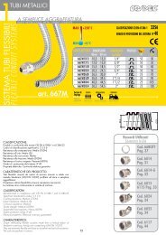
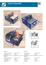
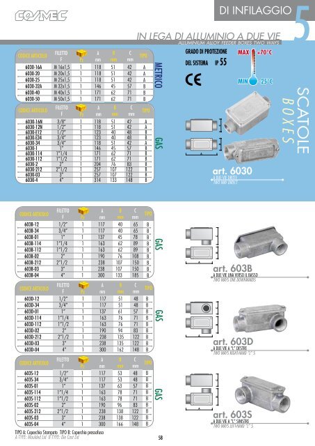
CODICE ARTICOLOCODICE ARTICOLOFILETTOFFILETTOFAmmAmmBmmBmmCmmPz6030-16A M 16x1,5 1 118 51 426030-20 M 20x1,5 1 118 51 426030-25 M 25x1,5 1 118 51 426030-32A M 32x1,5 1 146 45 576030-40 M 40x1,5 1 171 62 716030-50 M 50x1,5 1 171 62 71CmmPz6030-16N 3/8” 1 118 51 426030-12N 1/2” 1 118 51 426030-E12 1/2” 1 123 40 486030-E34 3/4” 1 123 40 486030-34 3/4” 1 118 51 426030-1 1” 1 146 45 576030-114 1”1/4 1 171 62 716030-112 1”1/2 1 171 62 716030-2 2” 1 204 76 836030-212 2”1/2 1 257 107 1226030-03 3” 1 257 107 1226030-4 4” 1 314 133 148TIPOAAABBBTIPOAABBABBBBBBBMETRICOGASADI INFILAGGIO5IN LEGA DI ALLUMINIO A DUE VIEalluminium alloy feeder boxes two waysGRADO DI PROTEZIONEDEL SISTEMA IP 55B CMAXMINart. 6030A DUE VIE DRITTETWO WAY DIRECT+70°C-25°C<strong>SCA</strong><strong>TOLE</strong>B O X E SCODICE ARTICOLOFILETTOA B CF Pz mm mm mm603B-12 1/2” 1 117 40 65603B-34 3/4” 1 117 40 65603B-01 1” 1 137 45 78603B-114 1”1/4 1 163 62 89603B-112 1”1/2 1 163 62 89603B-02 2” 1 190 76 108603B-212 2”1/2 1 238 107 150603B-03 3” 1 238 107 150603B-04 4” 1 300 133 185CODICE ARTICOLOFILETTOA B CF Pz mm mm mm603D-12 1/2” 1 117 51 48603D-34 3/4” 1 117 51 48603D-01 1” 1 137 61 57603D-114 1”1/4 1 163 76 71603D-112 1”1/2 1 163 76 71603D-02 2” 1 190 94 83603D-212 2”1/2 1 238 135 122603D-03 3” 1 238 135 122603D-04 4” 1 300 162 148CODICE ARTICOLOFILETTOA B CF Pz mm mm mm603S-12 1/2” 1 117 53 48603S-34 3/4” 1 117 53 48603S-01 1” 1 137 63 57603S-114 1”1/4 1 163 78 71603S-112 1”1/2 1 163 78 71603S-02 2” 1 190 96 83603S-212 2”1/2 1 238 138 122603S-03 3” 1 238 138 122603S-04 4” 1 300 166 148TIPO A: Coperchio Stampato TIPO B: Coperchio pressofusoA TYPE: Moulded Lid B TYPE: Die Cast LidTIPOBBBBBBBBBTIPOBBBBBBBBBTIPOBBBBBBBBBGASGASGAS58AAAB Cart. 603BA DUE VIE UNA VERSO IL BASSOTWO WAYS ONE DOWNWARDSB Cart. 603DA DUE VIE A “L” DESTRETWO WAYS RIGHT-HAND “L” SB Cart. 603SA DUE VIE A “L” SINISTRETWO WAYS LEFT-HAND “L” S
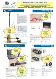
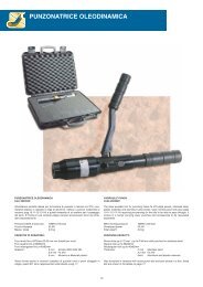
5DI INFILAGGIO<strong>SCA</strong><strong>TOLE</strong>B O X E SIN LEGA DI ALLUMINIO A TRE VIEfeeder boxes three waysGRADO DI PROTEZIONEDEL SISTEMA IP 55MAXMIN+70°C-25°Cart. 6330AA “T”“T” TYPEB CMETRICOGASCODICE ARTICOLOFILETTOA B CF Pz mm mm mm6330-16A M 16x1,5 1 118 67 426330-20 M 20x1,5 1 118 67 426330-25 M 25x1,5 1 118 67 426330-32A M 32x1,5 1 146 63 576330-40 M 40x1,5 1 171 78 716330-50 M 50x1,5 1 171 78 71CODICE ARTICOLOFILETTOA B CF Pz mm mm mm6330-16 3/8” 1 118 67 426330-12 1/2” 1 118 67 426330-E12 1/2” 1 123 53 486330-E34 3/4” 1 123 53 486330-34 3/4” 1 118 67 426330-1 1” 1 146 63 576330-114 1”1/4 1 171 78 716330-112 1”1/2 1 171 78 716330-2 2” 1 204 96 836330-212 2”1/2 1 257 138 1226330-3 3” 1 257 138 1226330-4 4” 1 314 166 148TIPOAAABBBTIPOAABBABBBBBBBart. 633BA “T” CON UNA SUL FONDO“T” TYPE WITH ONE ON THE BASEAB CGASCODICE ARTICOLOFILETTOA B CF Pz mm mm mm633B-12 1/2” 1 123 40 65633B-34 3/4” 1 123 40 65633B-01 1” 1 146 45 78633B-114 1”1/4 1 171 62 89633B-112 1”1/2 1 171 62 89633B-02 2” 1 204 76 108633B-212 2”1/2 1 257 107 150633B-03 3” 1 257 107 150633B-04 4” 1 314 133 185TIPOBBBBBBBBBSettori diImpiegoareas ofapplicationINDUSTRIALEINDUSTRIALBORDO MACCHINAINSTALLED ON MACHINESTIPO A: Coperchio Stampato TIPO B: Coperchio pressofusoA TYPE: Moulded Lid B TYPE: Die Cast Lid<strong>SCA</strong><strong>TOLE</strong> DI INFILAGGIOCOD. 6030 - 603B - 603D - 603S - 6330633B - 6430 - 603VScatole di infilaggio pressofuse in lega di alluminio UNI EN 1706 (exUNI 4514) con imbocchi filettati. Vengono prodotte a due, tre e quattrovie, con imbocchi in asse o perpendicolari, per meglio assecondare leesigenze di installazione.I coperchi sono avvolgenti e le guarnizioni piane assicurano una tenutastagna IP55. I coperchi vengono forniti in lega di allumino pressofuso(tipo B) o lamiera di alluminio stampato (tipo A) a seconda dell’articolorichiesto.Le viti di fissaggio del coperchio e di messa a terra sono prodotte inacciaio zincato, a richiesta possono essere fornite in acciaio inox AISI304.Per una corretta esecuzione dell’impianto elettrico, le scatole di infilaggioandrebbero installate ogni 4 tratte rettilinee di tubo, per evitare rischi didanneggiamento dell’isolamento durante l’infilaggio dei cavi.Le filettature proposte sono: Metrico ISO in conformità con le norme CEIEN 60423 e GAS cilindrico UNI ISO 228.59FEEDER BOXESPART Nos. 6030 - 603B - 603D - 603S - 6330633B - 6430 - 603VUNI EN 1706 (ex UNI 4514) die cast aluminium alloy feeder boxeswith threaded mouthpieces. Produced with two, three or four paths, withmouthpieces that are vertical or perpendicular to cope with different kinds ofinstallation requirements. The wrap-around lids and surface seals guaranteeIP55 water tightness. They are supplied in die cast aluminium alloy (B type)or moulded sheet aluminium (A type) depending on the item ordered.The screws for securing the lid as well as the grounding screws are madeof galvanised steel, but can also be supplied in AISI 304 stainless onrequest.For the electrical system to operate correctly, the feeding boxes should beinstalled every 4 straight lengths of piping, which will avoid the possibilityof the isulation being damaged whilst the cables are being fed through.Suggested threads are: ISO metric in compliance with CEI EN 60423 andUNI ISO 228 GAS cylindrical.
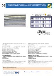
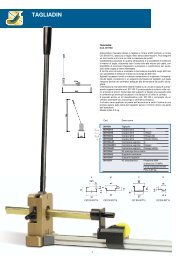
CODICE ARTICOLOFILETTOA B CF Pz mm mm mm6430-16A M 16 x 1,5 1 118 83 426430-20 M 20 x 1,5 1 118 83 426430-25 M 25 x 1,5 1 118 83 426430-32A M 32 x 1,5 1 146 81 576430-40 M 40 x 1,5 1 171 96 716430-50 M 50 x 1,5 1 171 96 71CODICE ARTICOLOFILETTOA B CF Pz mm mm mm6430-16 3/8” 1 118 83 426430-12 1/2” 1 118 83 426430-E12 1/2” 1 123 68 486430-E34 3/4” 1 123 68 486430-34 3/4” 1 118 83 426430-1 1” 1 146 81 576430-114 1”1/4 1 171 96 716430-112 1”1/2 1 171 96 716430-2 2” 1 204 118 836430-212 2”1/2 1 257 164 1226430-3 3” 1 257 164 1226430-4 4” 1 314 196 148TIPOAAAABBTIPOAABBAABBBBBBMETRICOGASMAXMIN+70°C-25°CB CDI INFILAGGIO5IN LEGA DI ALLUMINIO A QUATTRO VIE - A DUE VIE A 90°feeder boxes four ways - two ways 90°Aart. 6430A QUATTRO VIEFOUR WAYGRADO DI PROTEZIONEDEL SISTEMA IP 55<strong>SCA</strong><strong>TOLE</strong>B O X E SCODICE ARTICOLOFILETTOA B CF Pz mm mm mm603V-12 1/2” 1 130 64 44603V-34 3/4” 1 130 64 44603V-01 1” 1 148 73 50603V-112 1”1/2 1 182 103 71603V-02 2” 1 211 118 83603V-212 2”1/2 1 310 156 115TIPOBBBBBBGASAB Cart. 603VA “DUE VIE A 90°TWO WAY 90°TIPO A: Coperchio Stampato TIPO B: Coperchio pressofusoA TYPE: Moulded Lid B TYPE: Die Cast Lid60
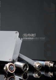
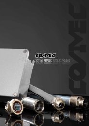
5<strong>SCA</strong><strong>TOLE</strong>B O X E SDI DERIVAZIONEIN LEGA DI ALLUMINIO VERNICIATO - IP66/IP67alluminium alloy painted junction boxes ip66MAXMIN+90°C-25°Cingombri esterni mminterni utili mmfissaggi a parete mmExternal dimensionsInternal dimensionsWall fasteningsCODICEd a b a s eARTICOLOPz A B C A B C D E Fp i a s t r a65300 32 100 100 59 90 90 53 / 6 80 8665301 24 140 115 60 128 103 55 45 6 120 10065302 16 166 142 64 154 129 58 48 7 144 12565303 12 192 168 80 178 155 74 64 6.5 168 14965304 6 253 217 93 239 202 85 75 9 226 19665305 2 314 264 122 294 244 114 104 9 275 23665306 1 410 315 153 392 298 144 127 9 367 283FilettaturaThreadDerivazioni consigliate per singolo lato con tubi metallici rigidi fissati mediante ghiera metrica a base pianaShunts recommended for individual sides with rigid metal conduits attached using a flat metric ring nut.LatoA65300 65301 65302 65303 65304 65305 65306LatoBLatoALatoBLatoALatoBM16 2 2 3 2 3 3 4 4 5 5 6 6 9 7M20 2 1 2 2 3 2 3 3 5 4 5 5 8 6M25 1 1 2 2 2 2 3 3 4 4 4 4 6 5M32 1 1 1 1 2 1 2 2 3 3 4 3 5 4M40 / / / / / / 2 2 2 2 3 3 4 3M50 / / / / / / 1 1 2 2 2 2 4 3M63 / / / / / / / / 2 1 2 2 3 2LatoALatoBLatoALatoBLatoALatoBLatoALatoBart. 65300 - 65306669500741Kit per fissaggi interni e messa a terra (n°1 vite 4 x 8 mm + n°1 inserito di fissaggio)Kit for internal and grounding fixings (no.1 screw 4x8mm + no.1 screw ancher)FBESettori diImpiegoareas ofapplicationTERZIARIO INDUSTRIALE CHIMICO FARMACEUTICO ALIMENTARE PRODUZIONE ENERGIA INFRASTRUTTURE BORDO MACCHINA FERROVIARIO MARINOTERTIARY SECTOR INDUSTRIAL CHEMICAL AND PHARMACEUTICAL INDUSTRY FOOD INDUSTRY ENERGY PRODUCTION INFRASTRUCTURE INSTALLED ON MACHINES RAILWAY INDUSTRY MARITIME INDUSTRYADCColori DisponibiliColoursGRIGIO RAL 9006 METALLIZZATO BUCCIATOTEXTURED RAL 9006 METALLIC GREYAumentati i fissaggiinterni per unamaggiore versatilità.Internal attachementshave been increasedto improve theadaptability.CLASSIFICAZIONE:Prodotti in conformità alle norme CEI EN 60670 e CEI 23-48Grado di protezione secondo EN 60529: IP66/IP67Resistenza agli urti secondo CEI EN 50102: IK07Proprietà elettriche: Continuità elettrica garantitaCARATTERISTICHE DEL PRODOTTO:Scatole di derivazione realizzate in lega di alluminio EN AB 46100 (ex.UNI 5076) secondo norme UNI EN 1676, verniciate a forno con resineepossidiche.Vengono fornite con pareti chiuse e coperchio avvolgente, la guarnizionein EPDM espanso già alloggiata nella sede del coperchio, ne assicura latenuta stagna. Complete di viti in acciaio inox AISI 304 per il fissaggiodel coperchio e di n.2 kit di messa a terra cod 66950074, le scatolesono predisposte con i masselli per messa a terra e per l’applicazione dipiastre, supporti ed accessori. Il fissaggio a parete avviene mediante lestaffe esterne incorporate nella base.Ogni scatola è confezionata singolarmente.I kit per i fissaggi interni sono disponibili a richiesta. Si realizzano foratureed equipaggiamenti su specifica del cliente.NOTA: per applicazioni particolari è necessario specificare l’impiego infase d’ordine.61CLASSIFICATION:Manufactured in compliance with CEI EN 60670 and CEI 23-48standardsSystem protection in accordance with EN 60529 standard: IP66/IP67Impact resistance in accordance with CEI EN 50102, Rating : IK07Electrical Properties: Electrical continuity guaranteedCHARACTERISTICS :Junction boxes made of aluminium alloy EN AB 46100 (ex. UNI 5076) inconformity with UNI EN 1676, oven-cured epoxy resin finish.They are supplied with closed walls and wrap-around cover; the EPDMfoam seal pre-fitted into the cover guarantees a seal level of. Complete withAISI 304 stainless steel screws to fasten the cover and 2 grounding kit codeno. 66950074, the boxes come equipped with blocks for grounding andattaching plates, brackets and accessories. They are attached to the wallusing the external brackets included in the base.Each box is packaged individually.Kits for internal attachment are available on request. Special drilling andequipment to customer specifications.PLEASE NOTE: For special applications, the end-use must be specified atthe time the order is placed.
DI DERIVAZIONE ATEX5IN LEGA DI ALLUMINIO VERNICIATO - IP66atex alluminium alloy painted junction boxes ip66ingombri esterni mminterni utili mmfissaggi a parete mmExternal dimensionsInternal dimensionsWall fasteningsCODICEd a b a s eARTICOLOPz A B C A B C D E Fp i a s t r a65300EX 32 100 100 59 90 90 53 / 6 80 8665301EX 24 140 115 60 128 103 55 45 6 120 10065302EX 16 166 142 64 154 129 58 48 7 144 12565303EX 12 192 168 80 178 155 74 64 6.5 168 14965304EX 6 253 217 93 239 202 85 75 9 226 19665305EX 2 314 264 122 294 244 114 104 9 275 23665306EX 1 410 315 153 392 298 144 127 9 367 283FilettaturaThreadLatoANumero massimo di pressacavi per latoMaximum number of cable glands for side65300 65301 65302 65303 65304 65305 65306LatoBLatoALatoBLatoALatoBM16 2 1 3 2 3 3 4 4 6 5 6+6 6+6 8+8 7+7M20 1 1 2 2 3 2 3 3 4 4 5+5 5+5 6+6 5+5M25 / / / / 2 2 3 2 3 3 4 4 5+5 4+4M32 / / / / / / 2 2 3 2 3 3 5 4M40 / / / / / / / / 2 2 3 3 4 3LatoALatoBLatoALatoBLatoALatoBLatoALatoBMAXMIN+60°C(+90°C SUPERFICIALE - SURFACE TEMPERATURE)-20°CII 3 GD<strong>SCA</strong><strong>TOLE</strong>B O X E SColori DisponibiliColoursSettori diImpiegoareas ofapplicationGRIGIO RAL 7037 BUCCIATOTEXTURED RAL 7037 GREYTERZIARIO INDUSTRIALE INFRASTRUTTURE BORDO MACCHINATERTIARY SECTOR INDUSTRIAL INFRASTRUCTURE INSTALLED ON MACHINESCLASSIFICAZIONE:In accordo alla direttiva ATEX 94/9/CE, prodotti in conformità allenorme: EN 61241-0: 2006, EN 61241-1: 2004, EN 60079-0: 2006,EN 60079-15: 2005, EN 60670-22.Classificazione: Componenti gruppo II – Categoria 3GDMarcatura identificativa del modo di protezione: II 3GD Ex nA ExtD A22 IP66 T90°C UGrado di protezione secondo EN 60529: IP66Temperatura max superficiale ammissibile: +90°CProprietà elettriche: Continuità elettrica garantitaSETTORI DI IMPIEGO:Installazioni fisse in ambienti a potenziale rischio di esplosioneidentificati come Zona 2 e Zona 22 in base alle norme EN 61241-0ed EN 60079-0.Buona resistenza agli agenti atmosferici, indicate per installazioniesterne. Per applicazioni particolari è necessario specificarne l’impiegoin fase d’ordine.CARATTERISTICHE DEL PRODOTTO:Scatole di derivazione realizzate in lega di alluminio EN AB 46100(ex. UNI 5076) secondo norme UNI EN 1676 e verniciate a forno conresine poliesteri.Vengono fornite con pareti chiuse e coperchio avvolgente, la guarnizionein EPDM espanso già alloggiata nella sede del coperchio, ne assicurala tenuta stagna IP66.Complete di viti in acciaio inox AISI 304 per il fissaggio del coperchio,di n.2 kit di messa a terra interno cod.66950074, n.1 kit messa a terraesterno (n.1 vite M4x8mm INOX + n.1 capocorda in rame stagnatosez. 6mm 2 + n.1 squadretta antirotazione), istruzioni d’installazione,uso e manutenzione.Internamente le scatole sono predisposte con i masselli per messa a terrae per l’applicazione di piastre, supporti ed accessori; esternamente èpresente un foro filettato per il collegamento al conduttore di terra.Il fissaggio a parete avviene mediante le staffe esterne incorporate nellabase.Ogni scatola è confezionata singolarmente.I kit per i fissaggi interni sono disponibili a richiesta.Si realizzano forature ed equipaggiamenti su specifica del cliente.AVVERTENZA:Scatole non equipaggiate classificate come componentiEx, possono essere impiegate solo in combinazione con altroequipaggiamento elettrico. Insieme necessitano di un’ulteriorecertificazione da aggiungere a quella già rilasciata da <strong>Cosmec</strong> s.r.l.62art. 65300EX -65306EXBEADFCLASSIFICATION:On the basis of ATEX directive 94/9/CE, they are produced in conformitywith the following standards: EN 61241-0: 2006, EN 61241-1: 2004,EN 60079-0: 2006, EN 60079-15: 2005, EN 60670-22.Classification: Components group II – Category 3GDProtection level marking: II 3GD Ex nA Ex tD A22 IP66 T90°C USystem protection standard in compliance with EN 60529: IP66Max. permitted surface temperature: +90°CElectrical properties: Electrical continuity guaranteedAPPLICATIONS:Permanent installations in environments with explosion hazard identifiedas Zone 2 and Zone 22 on the basis of EN standards 61241-0 and EN60079-0.Good resistance to atmospheric agents, suitable for external installations.For special applications, the end-use must be specified at the time the orderis placed.CHARACTERISTICS :Enhanced-safety junction boxes made of aluminium alloy EN AB 46100 (ex.UNI 5076) in conformity with UNI EN 1676, oven-cured polyester resinfinish.They are supplied with closed walls and wrap-around cover; the EPDM foamseal pre-fitted into the cover guarantees a seal level of IP66.Also included: AISI 304 stainless steel screws to fasten the cover; twointernal grounding kits code no. 66950074; one external grounding kit (oneM4x8mm stainless steel screw + one grounding lug in tinned copper section6mm 2 + antirotation bracket); installation, use and maintenance instructions.The interior of the boxes come equipped with blocks for grounding andattaching plates, brackets and accessories; the exterior has a threaded holefor connection to the grounding wire.They are attached to the wall using the external brackets included in the base.Each box is packaged individually.Kits for internal attachment are available on request.Special drilling and equipment to customer specifications.PLEASE NOTE:Non-equipped boxes classified as Ex components may beutilized only together with other electrical equipment. These units requirefurther certification in addition to that issued by <strong>Cosmec</strong> s.r.l.CAumentati i fissaggiinterni per unamaggiore versatilità.(vedi disegno pag. 61)Internal attachementshave been increased toimprove the adaptability.(see drawing page 61)
5DI DERIVAZIONE<strong>SCA</strong><strong>TOLE</strong>B O X E SIN LEGA DI ALLUMINIO VERNICIATO - IP65painted junction boxes ip65MAXMIN+100°C-30°Cingombri esterni mmExternal dimensionsinterni utili mmInternal dimensionsfissaggi a parete mmWall fasteningsCodICEARTICOLO Pz A B C a b da basepiastraØD E F65310 1 90 90 75 78 78 52 6,5 74 7465311 1 110 110 85 98 98 65 6,5 94 9465312 1 147 147 100 135 135 79 6,5 131 13165313 1 305 147 110 289 131 92 7,0 285 12765314 1 305 230 110 289 212 92 7,0 285 21065315 1 305 230 190 289 212 172 7,0 285 21065316 1 470 305 195 454 289 175 7,0 450 28565317 1 620 305 195 597 282 156 6,5 600 285art. 65310 - 65317ESettori diImpiegoareas ofapplicationTERZIARIO INDUSTRIALE CHIMICO FARMACEUTICO ALIMENTARE PRODUZIONE ENERGIA INFRASTRUTTURE BORDO MACCHINA FERROVIARIO MARINOTERTIARY SECTOR INDUSTRIAL CHEMICAL AND PHARMACEUTICAL INDUSTRY FOOD INDUSTRY ENERGY PRODUCTION INFRASTRUCTURE INSTALLED ON MACHINES RAILWAY INDUSTRY MARITIME INDUSTRYBAØDFCColori DisponibiliColoursGRIGIO RAL 7035 METALLIZZATO BUCCIATOTEXTURED RAL 7035 METTALLIC GREYCLASSIFICAZIONE:Prodotti in conformità alle norme CEI EN 60670 e CEI 23-48Grado di protezione secondo EN 60529: IP65Proprietà elettriche: Continuità elettrica garantitaCARATTERISTICHE DEL PRODOTTO:Scatole di derivazione realizzate in lega di alluminio pressofuso EN AB44100 (ex. UNI 4514) secondo norme UNI EN 1676, verniciate a fornocon resine epossidiche.Vengono fornite con pareti chiuse e coperchio avvolgente, la guarnizionein NBR assicura una tenuta stagna IP65.Complete di viti in acciaio inox per il fissaggio del coperchio e per lamessa a terra interna ed esterna, le scatole sono predisposte con i masselliper l’applicazione di piastre, supporti ed accessori.Il fissaggio a parete avviene mediante le staffe esterne incorporate nellabase.Ogni scatola è confezionata singolarmente.Le piastre per i fissaggi interni si producono a richiesta.Si realizzano forature ed equipaggiamenti su specifica del cliente.63CLASSIFICATION:Manufactured in compliance with CEI EN 60670 and CEI 23-48standardsSystem protection in accordance with EN 60529 standard, Rating : IP65Electrical Properties: Electrical continuity guaranteedCHARACTERISTICS :Junction boxes made of EN AB 44 100 (ex. UNI 4514) die cast aluminiumalloy in compliance with UNI EN 1676 standard, oven painted withepoxy resins.They are sold with closed sides and wrap-around lid, and a NBR sealguarantees the IP65 water tightness.Come complete with stainless steel screws to fix the lid and for internal andexternal grounding.The blocks for grounding and for fixing the support and accessories arepreinstalled.They are fixed to a wall by means of external brackets incorporated intothe base of the boxes.Each box is packaged individually.The base plates for internal fixing are manufactored on request.We can also supply drilling and equipment to customer specifications.
CodICE ARTICOLOingombri esterniExternal dimensionsAmmBmmCmminterni utiliInternal dimensionsAmmBmmCmmfissaggi a pareteWall fasteningsDmmEmm65300N 1 100 100 59 90 90 53 6 80 86669500741PzFmmDI DERIVAZIONE5MAX +90°CIN LEGA DI ALLUMINIO NICHEL RAMATO - IP66/ IP67die cast aluminium alloy ip66 copper plated nickel junction boxesKit per fissaggi interniKit for internal fastenings(n°1 vite 4x8 mm + n°1 tassello di fissaggio)(n°1 screw 4x8 mm + n°1 screw anchor)MIN-25°C<strong>SCA</strong><strong>TOLE</strong>B O X E SSettori diImpiegoareas ofapplicationTERZIARIOTERTIARY SECTORart. 65300NEFBADCCLASSIFICAZIONE:Normative di riferimento: CEI EN 60670, CEI 23-48Grado di protezione secondo CEI EN 60529: IP 66/IP 67Resistenza agli urti secondo CEI EN 50102: IK 08Proprietà elettriche: Continuità elettrica garantitaCARATTERISTICHE DEL PRODOTTO:Scatole di derivazione realizzate in lega di alluminio EN AB 46100 (ex.UNI 5076) secondo norme UNI EN 1676 e sottoposte ai trattamentigalvanici di nichelatura e ramatura.L’elevato spessore dei rivestimenti elettrolitici, conferisce una buonaresistenza agli agenti atmosferici ed un aspetto estetico analogoai particolari realizzati in leghe di rame, incluso il fenomeno diinvecchiamento.Vengono fornite con pareti chiuse e coperchio avvolgente, la guarnizionein EPDM espanso già alloggiata nella sede del coperchio, ne assicurala tenuta stagna.Complete di viti ramate in acciaio inox AISI 304 per il fissaggio delcoperchio e di n.2 kit di messa a terra cod 66950074, sono predispostecon i masselli per la messa a terra e per l’applicazione di piastre,supporti ed accessori.Il fissaggio a parete avviene mediante le staffe esterne, incorporatenella base della scatola.Ogni particolare è confezionato singolarmente.64CLASSIFICATION:Standard References: CEI EN 60670, CEI 23-48System Protection Standard : CEI EN 60529, Rating : IP66/IP67Impact resistance Standard : CEI EN 50102, Rating : IK 08Electrical Properties : Electrical continuity guaranteedCHARACTERISTICS :Junction boxes made of aluminium alloy EN AB 46100 (formerly UNI 5076)in compliance with UNI EN 1676 standard; nickel- and copper-plated.The thick electrolytic coating provides elevated resistance to atmosphericagents and its appearance is similar to that of copper alloys, includingaging.They are supplied with closed walls and wrap-around cover; the EPDM foamseal pre-fitted into the cover guarantees a seal level.Complete with AISI 304 copper-plated stainless steel screws to fasten thecover and 2 grounding kit code no. 66950074, they come equipped withblocks for grounding and attaching plates, brackets and accessories.They are attached to the wall using the external brackets included in the baseof the box.Each item is packaged individually.
5DI DERIVAZIONE E PULSANTIEREIN ACCIAIO INOX - IP66stainless steel junction boxes and push button panelsMAX+70°C<strong>SCA</strong><strong>TOLE</strong>B O X E SBart. 6410<strong>SCA</strong><strong>TOLE</strong> DI DERIVAZIONESTAINLESS STEEL JUNCTION BOXESMIN-50°CCODICEARTICOLOAmmBmmCmmrif. piastraDI FONDOPz6410E01 1 82 82 86 -6410E02 1 82 142 86 6410P026410E03 1 82 202 86 6410P036410E04 1 152 132 86 6410P046410S06 1 190 150 125 6410P066410S09 1 210 190 125 6410P096410S12 1 270 190 125 6410P126410S16 1 270 240 125 6410P166412F2Kit per il fissaggio a pareteKits to attach to wallsB= F=Aart. 6411PULSANTIEREPUSH BUTTON PANELSCCODICEARTICOLOSettori diImpiegoareas ofapplicationAmmBmmCmmGmmFmmCHIMICO FARMACEUTICO ALIMENTARE INFRASTRUTTURE BORDO MACCHINACHEMICAL AND PHARMACEUTICAL INDUSTRY FOOD INDUSTRY ENERGY PRODUCTION INFRASTRUCTURErif. piastradi fondoPz6411E01 1 82 82 86 -6411E02 1 82 142 86 60 6410P026411E03 1 82 202 86 60 6410P036411E04 1 152 132 86 60 60 6410P046411S06 1 190 150 125 60 50 6410P066411S09 1 210 190 125 50 60 6410P096411S12 1 270 190 125 50 60 6410P126411S16 1 270 240 125 50 60 6410P16=G G =AC<strong>SCA</strong><strong>TOLE</strong> DI DERIVAZIONE E PULSANTIERE INACCIAIO INOX COD. 6410 - 6411CLASSIFICAZIONE:Grado di protezione secondo CEI EN 60529 = IP 66Proprietà elettriche: Continuità elettrica garantitaResistenza alla corrosione: AltaCARATTERISTICHE:Sono prodotte in acciaio inox AISI 304 (X5CrNi1810 1.4301 UNI EN10088-1) finemente satinato, di robusta costruzione, ricavate da ununico foglio di lamiera di acciaio inox spessore 1,2 mm. Questa vienetranciata, stampata e saldata in atmosfera inerte per evitare fenomeni dicorrosione.La guarnizione in gomma neoprenica espansa, antiolio ed autoestinguente,già alloggiata nel coperchio, garantisce la tenuta stagna IP66.Sono complete di viti antiperdenti per il fissaggio del coperchio epredisposte per la messa a terra come da normative vigenti.Sul fondo della scatola sono applicati prigionieri M6 inox per il fissaggiodi profili portanti o delle piastre di fondo (eccetto cod.6410E01 ecod.6411E01).La serie 6411 è forata sul coperchio per pulsantiera normalizzataØ22,5mm; la disposizione delle forature è individuabile tramite tabelle edisegni sopra riportati.I kit per il fissaggio a parete cod.6412F sono da richiedere separatamentee vengono facilmente applicati praticando un foro Ø8mm sul fondo dellascatola; il grado IP è garantito dalle guarnizioni di tenuta incluse nel kit.65STAINLESS STEEL JUNCTION BOXES AND KEYPADS IP66COD. 6410-6411CLASSIFICATION:System protection in accordance with EN 60529 standard, Rating : IP66Electrical Properties: Electrical continuity guaranteedCorrosion resistance: HighCHARACTERISTICS :AISI 304 (X5CrNi1810 1.4301 UNI EN 10088-1) finely satin-finishstainless steel junction boxes, of a sturdy construction, made from a single,1.2 mm thick sheet of stainless steel.This is trimmed, pressed and then welded in an inert environment in order toprevent the possibility of corrosion.A neoprene rubber seal that is both oil resistant and self-extinguishing, andpre-fitted into the lid ensures IP66 water tightness.They come complete with leakproof screws to fasten the lid and groundingas required by law.M6 stainless steel stud bolts are placed on the base of the boxes toattach the frame and base plates (except for COD. 6410E01 and COD.6411E01).The 6411 series is drilled on the lid for a diameter dimension of 22.5mm;the location of the holes can be identified by referring to the tables anddrawings above.The kits to attach to walls COD. 6412F must be requested separately andthey can be attached easily by piercing a hole for a diameter dimension of8mm; IP rating is guaranteed by the leakproof seals included inside the kit.
<strong>SCA</strong><strong>TOLE</strong> PER TUNNEL HIGHWAY TUNNEL SYSTEMSIn questi anni stiamo assistendo ad un intensificarsi di nuove infrastrutture stradali, ferroviarie e metropolitane.I nuovi sistemi di perforazione delle gallerie consentono di realizzare in tempi relativamente brevi attraversamenti montani, oin aree metropolitane agevolando in tal modo il miglioramento della viabilità.Gli incidenti successi in alcune gallerie autostradali hanno evidenziato la necessità di regolamentare tutti i servizi tecnologicidi supporto, al fine di migliorare il livello di sicurezza, a partire dagli impianti antincendio per arrivare non ultimi a quellisonori e di illuminazione, atti a garantire l’integrità degli impianti per un tempo reputato sufficiente alla messa in sicurezzadelle persone.Naturalmente l’esigenza di sicurezza interessa anche le gallerie di vecchia costruzione, e pertanto nei prossimi anni assisteremoad un intensificarsi di attività necessarie ad assolvere questo scopo.La COSMEC s.r.l.,da anni produttrice di sistemi di protezione cavi in ambito industriale, ha voluto cimentarsi in questo interessantesettore proponendo, oltre ai tubi ed alle raccorderie in acciaio inox, una serie di cassette di derivazione metallicheallestiste secondo richiesta, con lo scopo di poter soddisfare le esigenze degli installatori.Tali cassette sono state testate presso Istituti certificati al fine di comprovare l’idoneità dei componenti a garantire la continuitàelettrica in caso d’incendio.L’omologazione FIRE PROOFgarantisce il superamento delle prove di funzionamentopreviste dalle linee guide ANAS riferite agli impianti di illuminazione, sicurezza ed estrazione fumi.Per soddisfare al meglio i requisiti previsti dalle molteplici soluzioni d’impianto, COSMEC s.r.l. propone diverse linee di prodotti,con caratteristiche ed omologazioni specifiche.La famiglia di cassette 640F in lamiera di acciaio, opportunamente trattata e verniciata, garantisce una resistenza allacorrosione a 720 h in nebbia salina ed insieme alla famiglia 640X in acciaio inox AISI 304/316, hanno superato laprova in forno a 920°C per 20’ in conformità alla norma NF C32-070 (rapporto di prova CSI n.DC02/011/F05).La famiglia di cassette T65304HT in alluminio verniciato ha superato la prova in forno a 400°C per 300’ (rapporto diprova INTEC n. RP 07-0017) e la prova prevista per i cavi a 850°C per 90’ in conformità alla norma CEI EN 50362 I^ ed.2003 (rapporto di prova IMQ n.01SH0015/1).Riteniamo di poter proporre materiali altamente qualificati e rispondenti alle esigenze di sicurezza necessarie alle nuove evecchie infrastrutture accompagnate dalla versatilità e dalla abitudine ad affrontare, e risolvere le esigenze installative deinostri clienti.Rapporti di prova e certificazioni vedi pag.11.Recent years have seen an intensification of new road, rail and underground railway infrastructure.New tunnel drilling systems make it possible to create mountain and urban crossings in a relatively short amount of time, thus facilitatingtraffic flow.The accidents which have occurred in some highway tunnels have underscored the need for all technological support services tobe regulated in order to improve safety levels, from fire-fighting equipment to acoustic and lighting systems that guarantee systemreliability for the period of time deemed adequate for people to reach safety.Naturally, tunnels constructed in the past are also subject to the same safety considerations and, as a result, activity will also increasein this sector over the coming years.<strong>Cosmec</strong> S.r.l., with years of consolidated experience in the manufacture of industrial cable protection systems, has also taken on thischallenging sector, offering not only conduits and fittings in stainless steel, but also a series of custom-made metal junction boxes tomeet installer demands.These boxes have been tested by certifying bodies in order to verify that their components can guarantee continuity of electricalpower in the event of fire.FIRE PROOF certificationguarantees that the product has passed the performance tests specified inANAS guidelines for lighting, safety and fume extraction systems.To satisfy all the requisites of a wide range of system configurations, <strong>Cosmec</strong> S.r.l. offers a number of different product lines, eachwith its own characteristics and technical specifications.The 640F line of boxes in treated and painted sheet steel guarantees up to 720 hrs of salt fog corrosion resistance and, togetherwith the 640X line in AISI 304/316 stainless steel, passed the furnace test at 920°C for 20’ in conformity with NFC32-070 standards, test report CSI no. DC02/011/F05.The T65304HT line of boxes in painted aluminium passed the furnace test at 400°C for 300’ (INTEC test report no. RP 07-0017) and the furnace test at 850°C for 90’ in conformity with CEI EN 50362 ed. 1 2003 (test report IMQ 01SH00105/1).We are proud to offer high-quality materials that meet the safety needs required in new and old systems, coupled with our flexibilityand commitment to take on and solve the installation demands of our customers.Test and certifications reports on page 11.66
5Codice<strong>SCA</strong><strong>TOLE</strong>B O X E SSISTEMI PER TUNNEL<strong>SCA</strong><strong>TOLE</strong> IN LEGA D’ALLUMINIO per impianti di illuminazionealuminium alloy junction boxes for lighting systemsGRADO DI PROTEZIONE DEL SISTEMA IP 66/IP 67LINEA PASSANTE CON CAVI UNIPOLARI DERIVAZIONECON PRESSACAVI IN OTTONE NICHELATOCONNECTION CABLE WITH UNIPOLAR CABLESSHUNT WITH NICKEL-PLATED BRASS GLANDSCodice AllestimentoProduct CodeAllestimentoProduct CodeSezione caviCable SectionMorsetteriaTerminal StripPressacavi Linea Pressacavi derivazioneCable Gland Shunt GlandT65304HT-0616 T65304-0616 2x(1x4mm2 )n.4 M16 n.1 M252x16mm2x(1x6mm 2 )2(5÷9mm) (11÷16mm)n.4 M20 n.1 M25T65304HT-1620 T65304-1620 2x(1x10mm 2 ) 2x16mm 2 (8÷12mm) (11÷16mm)n.4 M25 n.1 M25T65304HT-1625 T65304-1625 2x(1x16mm 2 ) 4x16mm 2 (11÷16mm) (11÷16mm)T65304HT-4025 T65304-4025 2x(1x25mm2 )n.4 M25 n.1 M252x40mm2x(1x35mm 2 )2(11÷16mm) (11÷16mm)400 C° 120 C°850 C°T65304HT-0616P T65304-0616P 2x(1x4mm2 )2x(1x6mm 2 )PzNo. per pkg.Temp. di impiego: -25°C +90°C - Working Tempertaure : -25°C + 90°Cn.4 M16 n.1 Presa2x16mm 2(5÷9mm) 16A - 2P+Tn.1 Presa16A - 2P+Tn.1 Presa(11÷16mm) 16A - 2P+Tn.4 M25 n.1 Presa2x40mm 2(11÷16mm) 16A - 2P+Tn.4 M20T65304HT-1620P T65304-1620P 2x(1x10mm 2 ) 2x16mm 2 (8÷12mm)n.4 M25T65304HT-1625P T65304-1625P 2x(1x16mm 2 ) 4x16mm 2T65304HT-4025P T65304-4025P 2x(1x25mm2 )2x(1x35mm 2 )400 C° 120 C°Temp. di impiego: -25°C +80°C - Working Tempertaure : -25°C + 80°C11111111LINEA PASSANTE CON CAVI UNIPOLARI DERIVAZIONE CON PRESACONNECTION CABLE WITH UNIPOLAR CABLESSHUNT WITHCURRENT COLLECTORFONDO LINEA CON CAVI UNIPOLARI DERIVAZIONE CON PRESSACAVI INOTTONE NICHELATOLINE END WITH UNIPOLAR CABLES SHUNT WITH NICKEL-PLATED BRASSGLANDS850 C°T65304HT-0616F T65304-0616F 2x(1x4mm2 )n.2 M16 n.1 M252x6mm2x(1x6mm 2 )2(5÷9mm) (11÷16mm)n.2 M20 n.1 M25T65304HT-1620F T65304-1620F 2x(1x10mm 2 ) 2x16mm 2 (8÷12mm) (11÷16mm)n.2 M25 n.1 M25T65304HT-1625F T65304-1625F 2x(1x16mm 2 ) 4x16mm 2 (11÷16mm) (11÷16mm)T65304HT-4025F T65304-4025F 2x(1x25mm2 )n.2 M25 n.1 M252x40mm2x(1x35mm 2 )2(11÷16mm) (11÷16mm)Settori diImpiegoareas ofapplication400 C° 120 C°850 C°INFRASTRUTTUREINFRASTRUCTURETemp. di impiego: -25°C +90°C - Working Tempertaure : -25°C + 90°CColori DisponibiliColoursGRIGIO RAL 7037 BUCCIATOTEXTURED RAL 7037 GREY1111CLASSIFICAZIONE:Prodotti in conformità alle norme CEI 23-48 e relative IEC 670Grado di protezione secondo CEI EN 60529 = IP 66/IP 67Resistenza agli urti in conformità alle linee guida ANASProprietà elettriche: Continuità elettrica garantitaTemperatura massima di funzionamento: T65304 = +120°CT65304HT = +400°C per 300’ oppure +850°C per 90’Morsettiere: Autoestinguenza secondo UL94 = V0RAPPORTI DI PROVA E CERTIFICAZIONI :• Scatole T65304HT Rapporto di Prova INTEK n. RP 07-0017 conintegrità funzionale a 400 °C per 300’ verificata in forno in conformitàalla circolare ANAS 8 Set 99, prot.7735.• Scatole T65304HTRapporto di prova IMQ n. 01SH00105/1 attaa verificare la funzionalità a 850°C per almeno 90 minuti secondo lanorma EN 50362 in conformità alle linee guida ANAS.SETTORI D’IMPIEGO:Impianti d’illuminazione e segnalamento in gallerie stradali eferroviarie.CARATTERISTICHE GENERALI:Scatole pressofuse realizzate in lega d’alluminio EN AB46100 (ex UNI5076) secondo le norme UNI EN 1676. Gli speciali trattamenti67superficiali cui vengono sottoposte, garantiscono l’inalterabilità sia inambienti molto umidi, quali le gallerie, che in presenza di polvericorrosive generate dal traffico automobilistico.La guarnizione in EPDM espanso già alloggiata nella sede delcoperchio, ne assicura la tenuta stagna.Sono complete di viti per il fissaggio del coperchio (in acciaio inoxAISI304) e predisposte per la messa a terra interna ed esterna; ilfissaggio a parete avviene mediante le staffe incorporate nella base.Protezione della fase d’alimentazione del corpo illuminante mediantebase portafusibile ceramica tipo E14-D01, completa di fusibile.Morsettiera T65304 in materiale termoplastico modificato, antifiamma,priva d’alogeni e fosforo, emissione fumi I2 F2 secondo norma NF F16-101, fissata su profilo portante a norme DIN.Morsettiera T65304HT in ceramica altamente resistente all’infiammabilitàed alle correnti superficiali.Il collegamento a vite con staffa di fissaggio brevettata, consente unserraggio ermetico e sicuro contro le vibrazioni.Le scatole sono disponibili in diverse soluzioni già equipaggiate, permeglio assecondare le esigenze d’installazione.Dimensioni esterne della scatola: L253 x H217 x P93 mmAccessori utilizzati: Raccordi pressacavo IP68 in ottone nichelato; preseIP67 in tecnopolimero altamente resistente, dotate di ghiera con chiusuraa baionetta ed alveoli autocentranti in ottone con molla elastica, pergarantire una pressione di contatto costante ed uniforme.
SISTEMI PER TUNNEL5<strong>SCA</strong><strong>TOLE</strong> IN LEGA D’ALLUMINIO per impianti di illuminazionealuminium alloy junction boxes for lighting systemsGRADO DI PROTEZIONE DEL SISTEMA IP 66/ IP 67Codice AllestimentoProduct CodeT65304HT-0632 T65304-0632400 C° 120 C°850 C°Codice AllestimentoProduct CodeSezione caviCable SectionMorsetteriaTerminal Strip4x4mm 2n.2 M324x16mm4x6mm 2 2 (15÷21mm)T65304HT-1040 T65304-1040 4x10mm 2 6x16mm 2 n.2 M40(15÷27mm)T65304HT-1640 T65304-1640 4x16mm 2 6x16mm 2 n.2 M40(15÷27mm)Pressacavi Linea Pressacavi derivazioneCable Gland Shunt Glandn.1 M25(11÷16mm)n.1 M25(11÷16mm)n.1 M25(11÷16mm)PzNo. per pkg.Temp. di impiego: -25°C +90°C - Working Tempertaure : -25°C + 90°C111LINEA PASSANTE CON CAVI MULTIPOLARI DERIVAZIONE CONPRESSACAVI IN OTTONE NICHELATOCONNECTION CABLE WITH MULTIPOLAR CABLES SHUNTWITH NICKEL-PLATED BRASS GLANDS<strong>SCA</strong><strong>TOLE</strong>B O X E SCodice AllestimentoProduct CodeCodice AllestimentoProduct CodeT65304HT-0632P T65304-0632P400 C° 120 C°Sezione caviCable SectionMorsetteriaTerminal StripPressacavi LineaCable Gland4x4mm 2n.2 M324x16mm4x6mm 2 2 (15÷21mm)T65304HT-1040P T65304-1040P 4x10mm 2 6x16mm 2 n.2 M40(15÷27mm)T65304HT-1640P T65304-1640P 4x16mm 2 6x16mm 2 n.2 M40(15÷27mm)Pressacavi derivazioneShunt Gland PzNo. per pkg.n.1 Presa16A - 2P+Tn.1 Presa16A - 2P+Tn.1 Presa16A - 2P+TTemp. di impiego: -25°C +90°C - Working Tempertaure : -25°C + 90°C111850 C°LINEA PASSANTE CON CAVI MULTIPOLARI DERIVAZIONE CON PRESACONNECTION CABLE WITH MULTIPOLAR CABLES SHUNT WITHCURRENT CONNECTORCLASSIFICATION:Manufactured in compliance with CEI 23-48 and applicable IEC 670standardsSystem protection standard in compliance with CEI EN 60529: IP 66/IP 67Shock resistance standard in compliance with ANAS guidelinesElectrical properties: Electrical continuity guaranteedMaximum working temperature: T65304 = +120°CT65304HT = +400°C for 300’ or +850°C for 90’Terminal strips: Self-extinguishing in compliance with UL94 standard: V0TEST AND CERTIFICATION REPORTS:T65304T boxes – INTEK test report no. RP 07-0017 with workingintegrity to 400°C for 300’, furnace-checked in conformity with ANASmemo dated Sept. 8, 1999, file no. 7735.T65304HT boxes – IMG test report no. 01sh00105/1 to checkperformance at 850°C for at least 90 minutes in conformity with EN50362 standards and ANAS guidelines..APPLICATIONS:Lighting systems and signal lights in road and rail tunnels.CHARACTERISTICS :Die cast junction boxes made of UNI EN1706 (prev. UNI 5076)aluminium alloy. special surface treatments guarantee that performancewill remain unaltered in both very humid environments (such as tunnels), as68well as in the presence of corrosive particles generated by road traffic.The EPDM foam seal pre-fitted into the cover guarantees a seal level.They include screws to attach the cover (in AISI304 stainless steel) as wellas internal and external grounding; may be attached to a wall using thesupports built-in at the base.Lighting device protected during power phase by a fuse with E14-D01ceramic fuse holder.The T65304 terminal strip is made of modified thermoplastic that is flameproofand halogen- and phosphorous-free with fume emission level I2 F2 inconformity with NF F 16-101 standards; it is attached to the main frame incompliance with DIN standards.The T65304HT terminal strip is made of ceramic material highly-resistantto flame and surface power currents.Screw fastening with patented clamp provides an air/water-tight seal thatis also vibration-proof.The boxes are available in a range of pre-equipped models to meet allinstallation requirements.BOX DIMENSIONS: 253L x 217H x 93P mmComponents: IP68 glands in nickel-plated brass; IP67 seals in highlyresistanttechnopolymers with ring nuts with bayonet clutch locking andself-centring brass openings with flexible spring to guarantee uniformcontact pressure.
5SISTEMI PER TUNNEL<strong>SCA</strong><strong>TOLE</strong> IN ACCIAIO VERNICIATO per impianti di sicurezzapainted steel junction boxes for safety systemsGRADO DI PROTEZIONE DEL SISTEMA IP 66<strong>SCA</strong><strong>TOLE</strong>B O X E SLINEA PASSANTE DERIVAZIONE CON PRESSACAVI INOTTONE NICHELATOCONNECTION CABLE SHUNT WITH NICKEL-PLATEDBRASS GLAND<strong>SCA</strong>VI UNIPOLARICAVI MULTIPOLARICodice Allestimento Sezione cavi Morsetteria Pressacavi Linea Pressacavi derivazioneProduct Code Cable Section Terminal Strip Cable Gland Shunt Gland2x(1x4mm640F-06162 )n.4 M16 n.1 M252x16mm2x(1x6mm 2 )2(5÷9mm) (11÷16mm)n.4 M20 n.1 M25640F-1020 2x(1x10mm 2 ) 2x16mm 2 (8÷12mm) (11÷16mm)n.4 M20 n.1 M25640F-1620 2x(1x16mm 2 ) 4x16mm 2 (8÷12mm) (11÷16mm)Temp. di impiego: -20°C +80°C - Working Tempertaure : -20°C + 80°C920°CTemp. massima di funzionamento: +920°C per 20’in fornoMaximum working temperature : +920°C for 20’ in the ovenCodice AllestimentoProduct Code640F-06324x4mm 2n.2 M324x16mm4x6mm 2 2 (15÷21mm)640F-1040 4x10mm 2 4x16mm 2 n.2 M40(15÷27mm)640F-1640 4x16mm 2 6x16mm 2 n.2 M40(15÷27mm)920°CSezione caviCable SectionMorsetteriaTerminal StripPressacavi Linea Pressacavi derivazioneCable Gland Shunt Glandn.1 M25(11÷16mm)n.1 M25(11÷16mm)n.1 M25(11÷16mm)Temp. di impiego: -20°C +80°C - Working Tempertaure : -20°C + 80°CTemp. massima di funzionamento: +920°C per 20’in fornoMaximum working temperature : +920°C for 20’ in the ovenPzNo. per pkg.111PzNo. per pkg.111Settori diImpiegoareas ofapplicationINFRASTRUTTUREINFRASTRUCTUREColori DisponibiliColoursGRIGIO RAL 7032 BUCCIATOTEXTURED RAL 7032 GREYCLASSIFICAZIONE:Prodotti in conformità alle norme CEI 23-48 e relative IEC 670Grado di protezione secondo CEI EN 60529 = IP 66Resistenza agli urti in conformità alle linee guida ANASProprietà elettriche: Continuità elettrica garantitaTemperatura massima di funzionamento: +920°C per 20’Morsettiera: Autoestinguenza secondo UL94 = V0RAPPORTI DI PROVA E CERTIFICAZIONI :• Rapporto di Prova CSI n. DC02/011/F05Scatola con integrità funzionale a 920 °C per 20’ verificata in forno inconformità alle norme NF C32-070• Rapporto di prova Klippon Electicals LtdMorsetti con continuità elettrica garantita a 1000 °C per 20’ o 750 °Cper 3 ore• Test Report NEMKO Spa n. 000081IND1/03Scatola in nebbia salina per 720 ore secondo IEC60068-2-11• RINA Type Approval certificate no. ELE93303CSSETTORI DI IMPIEGO:Impianti di sicurezza in gallerie stradali e ferroviarie; garantiscono lacontinuità di servizio in condizioni d’incendio.CARATTERISTICHE GENERALI:Scatole ricavate da lamiera d’acciaio con spessore 12/10mm. Gli specialitrattamenti superficiali cui vengono sottoposte, garantiscono l’inalterabilitàsia in ambienti molto umidi, quali le gallerie, che in presenza di polvericorrosive generate dal traffico automobilistico.La guarnizione in EPDM espanso già alloggiata nel coperchio, ne assicurala tenuta stagna.Sono complete di viti antisfilamento per il fissaggio del coperchio epredisposte per la messa a terra interna ed esterna; il fissaggio a pareteavviene mediante le staffe in acciaio già montate sulla base.Maggior sicurezza grazie alla doppia protezione (fase d’alimentazionee neutro) con basi portafusibile in ceramica tipo E14-D01 complete difusibili.Morsettiera in ceramica altamente resistente all’infiammabilità ed allecorrenti superficiali, fissata su profilo portante a norme DIN; il collegamentoa vite con staffa di fissaggio brevettata, consente un serraggio ermetico esicuro contro le vibrazioni.Le scatole sono disponibili in diverse soluzioni già equipaggiate, permeglio assecondare le esigenze d’installazione.Dimensioni esterne della scatola: L200 x H200 x P120mmAccessori utilizzati: Raccordi pressacavo IP68 in ottone nichelato.69CLASSIFICATION:Manufactured in compliance with CEI 23-48 and applicable IEC 670standardsSystem protection standard in compliance with CEI EN 60529: IP 66Shock resistance standard in compliance with ANAS guidelinesElectrical properties: Electrical continuity guaranteedMaximum working temperature: +920°C for 20’Terminal strip: Self-extinguishing in compliance with UL94 standard: V0TEST AND CERTIFICATION REPORTS:• CSI test report no. DC02/011/F05Box with functional integrity to 920°C for 20’, furnace checked in conformitywith NF C32-070 standards• Klippon Electricals Ltd test reportTerminal strips with electrical continuity guaranteed to 1000°C for 20’ or750°C for 3 hours• Test Report NEMKO Spa no. 000081IND1/03Box in salt fog for 720 hrs in conformity with IEC60068-2-11.• RINA Type Approval certificate no. ELE93303CSAREAS OF APPLICATION:Safety systems in road and rail tunnels; guarantee service continuity duringfiresCHARASTERISTICS:Boxes made of 12/10mm-thick steel sheet. Special surface treatmentsguarantee that performance will remain unaltered in both very humidenvironments (such as tunnels), as well as in the presence of corrosiveparticles generated by road traffic.The EPDM foam seal pre-fitted into the cover guarantees a seal level.They include 4 tamper-proof screws to attach the cover, as well as internaland external grounding; they may be attached to a wall using the steelsupports built-in to the base.Enhanced security thanks to double protection (supply phase and neutral)with fuses in E14-D01 ceramic fuse holders.The terminal strip is made of ceramic material highly-resistant to flame andsurface power currents; attached to the main frame in compliance with DINstandards.The boxes are available in a range of pre-equipped models to meet allinstallation requirements.BOX DIMENSIONS: 200L x 200H x 120P mmComponents: IP68 glands in nickel-plated brass.
SISTEMI PER TUNNEL5<strong>SCA</strong><strong>TOLE</strong> IN ACCIAIO INOX per impianti di sicurezzastainless steel junction boxes for safety systemsGRADO DI PROTEZIONE DEL SISTEMA IP 66Codice AllestimentoProduct Code640X-06162x(1x4mm 2 )2x(1x6mm 2 )2x16mm 2n.4 M16(5÷9mm)n.4 M20640X-1020 2x(1x10mm 2 ) 4x16mm 2 (8÷12mm)n.4 M20640X-1620 2x(1x16mm 2 ) 4x16mm 2920°CCodice AllestimentoProduct Code640X-0632Sezione caviCable SectionMorsetteriaTerminal StripPressacavi Linea Pressacavi derivazioneCable Gland Shunt Gland(8÷12mm)n.1 M25(11÷16mm)n.1 M25(11÷16mm)n.1 M25(11÷16mm)Temp. di impiego: -20°C +70°C - Working Tempertaure : -20°C + 70°CTemp. massima di funzionamento: +920°C per 20’in fornoMaximum working temperature : +920°C for 20’ in the oven4x4mm 2n.2 M324x16mm4x6mm 2 2 (15÷21mm)640X-1040 4x10mm 2 6x16mm 2 n.2 M40(15÷27mm)920°CSezione caviCable SectionMorsetteriaTerminal Strip640X-1640 4x16mm 2 6x16mm 2 n.2 M40(15÷27mm)Pressacavi Linea Pressacavi derivazioneCable Gland Shunt Glandn.1 M25(11÷16mm)n.1 M25(11÷16mm)n.1 M25(11÷16mm)Temp. di impiego: -20°C +70°C - Working Tempertaure : -20°C + 70°CTemp. massima di funzionamento: +920°C per 20’in fornoMaximum working temperature : +920°C for 20’ in the ovenPzNo. per pkg.111PzNo. per pkg.111CAVI UNIPOLARICAVI MULTIPOLARILINEA PASSANTE DERIVAZIONE CON PRESSACAVI INOTTONE NICHELATOCONNECTION CABLE SHUNT WITH NICKEL-PLATEDBRASS GLANDS<strong>SCA</strong><strong>TOLE</strong>B O X E SSettori diImpiegoareas ofapplicationINFRASTRUTTUREINFRASTRUCTURECLASSIFICAZIONE:Prodotti in conformità alle norme CEI 23-48 e relative IEC 670Grado di protezione secondo CEI EN 60529 = IP 66Resistenza agli urti in conformità alle linee guida ANASProprietà elettriche: Continuità elettrica garantitaTemperatura massima di funzionamento:+920°C per 20’Morsettiera: Autoestinguenza secondo UL94 = V0RAPPORTI DI PROVA E CERTIFICAZIONI :• Rapporto di Prova CSI n. DC02/011/F05Scatola con integrità funzionale a 920 °C per 20’ verificata in forno inconformità alle norme NF C32-070• Rapporto di prova Klippon Electicals LtdMorsetti con continuità elettrica garantita a 1000 °C per 20’ o 750 °Cper 3 ore• Rapporto di prova ALFLAB <strong>srl</strong> n. SIC 1222/94Grado di protezione IP 66 secondo CEI EN 60529SETTORI DI IMPIEGO:Impianti di sicurezza in gallerie stradali e ferroviarie; garantiscono lacontinuità di servizio in condizioni d’incendio.CARATTERISTICHE GENERALI:Sono prodotte in acciaio inox AISI 304 (X5CrNi1810 1.4301 UNI EN10088-1) finemente satinato, di robusta costruzione, ricavate da ununico foglio di lamiera di acciaio inox spessore 12/10 mm. Questaviene tranciata, stampata e saldata in atmosfera inerte per evitarefenomeni di corrosione.La guarnizione in EPDM espanso esente da CFC, antiolio edautoestinguente, già alloggiata nel coperchio, garantisce la tenutastagna IP66.Sono complete di viti antisfilamento per il fissaggio del coperchio, epredisposte per la messa a terra interna ed esterna;il fissaggio a pareteavviene mediante le staffe in acciaio inox già montate sulla base.Maggior sicurezza grazie alla doppia protezione (fase di alimentazionee neutro) con basi portafusibile in ceramica tipo E14-D01 complete difusibili.Morsettiera in ceramica altamente resistente all’infiammabilità edalle correnti superficiali, fissata su profilo portante a norme DIN;il collegamento a vite con staffa di fissaggio brevettata, consente unserraggio ermetico e sicuro contro le vibrazioni.Le scatole sono disponibili in diverse soluzioni già equipaggiate, permeglio assecondare le esigenze di installazione.Dimensioni esterne della scatola: L200 x H180 x P125 mmAccessori utilizzati: Raccordi pressacavo IP68 in ottone nichelato.70CLASSIFICATION:Manufactured in compliance with CEI 23-48 and applicable IEC 670standardsSystem protection standard in compliance with CEI EN 60529: IP 66Shock resistance standard in compliance with ANAS guidelinesElectrical properties: Electrical continuity guaranteedMaximum working temperature: +920°C for 20’Terminal strip: Self-extinguishing in compliance with UL94 standard: V0TEST AND CERTIFICATION REPORTS:• CSI test report no. DC02/011/F05Box with functional integrity to 920°C for 20’, furnace-checked in conformitywith NF C32-070 standards• Klippon Electricals Ltd test reportTerminal strips with electrical continuity guaranteed to 1000°C for 20’ or750°C for 3 hours• ALFLAB <strong>srl</strong> test report no. SIC 1222/94System protection standard in compliance with CEI EN 60529: IP 66APPLICATIONS:Safety systems in road and rail tunnels; guarantee service continuity duringfires.CHARASTERITICS:GENERAL CHARACTERISTICS:Manufactured in sturdy, fine satin finish AISI 304 stainless steel (X5CrNi18101.4301 UNI EN 10088-1) from a single sheet of 12/10 mm thick stainlesssteel sheet.The sheet is trimmed, pressed and inert gas welded to avoid corrosion.The CFC-free, oil-resistant and self-extinguishing EPDM foam seal pre-fittedinto the cover, guarantees a seal level of IP66.They include anti-leak screws to attach the cover, as well as internal andexternal grounding; they may be attached to a wall using the stainless steelsupports built-in to the base.Enhanced security thanks to double protection (supply phase and neutral)with fuses in E14-D01 ceramic fuse holders.The terminal strip is made of ceramic material highly-resistant to flame andsurface power currents; attached to the main frame in compliance with DINstandards; the screw fastening with patented clamp provides an air/watertightseal that is also vibration-proof.The boxes are available in a range of pre-equipped models to meet allinstallation requirements.BOX DIMENSIONS: 200L x 180H x 125P mmComponents: IP68 glands in nickel-plated brass.
5SISTEMI PER TUNNELPRESA-DECONTATTORE PER ESTRATTORI DI FUMIdecontactor plug-and-socket outlets for fume extractorsMAX+90°C(fino a 400°C per 120’)GRADO DI PROTEZIONE DEL SISTEMA IP 65MIN-25°C<strong>SCA</strong><strong>TOLE</strong>B O X E SSino ad oggi, in assenza di una Presa-sezionatore capacedi resistere alle condizioni della norma EN 12101-3, iventilatori/estrattori di fumi erano obbligatoriamentecollegati direttamente alla morsettiera, ciò complicando leoperazioni di manutenzione. Questo nuovo apparecchiopermette di alimentare gli estrattori costituendo al tempostesso un dispositivo di sezionamento dell’alimentazione(cf. articolo 5.3 e 5.4 della Norma EN 60204-1 -sicurezzadel macchinario – equipaggiamento elettrico delle macchine– Parte 1 :regole generali).Settori diImpiegoareas ofapplicationINFRASTRUTTUREINFRASTRUCTUREart. T65304HT-63690PRESA-DECONTATTORE PER ESTRATTORE DI FUMIDECONTACTOR PLUG-AND-SOCKET OUTLETS FORFUME EXTRACTORSTo date, without these decontactor plug-and-socket outlets able to handlethe conditions outlined in EN 12101-3, blowers/fume exhaust systemshave had to be connected directly to the terminal strip, a fact that makesmaintenance more complicated. This new unit makes it possible to powerexhaust extractors while, at the same time, offering a power supplycutoff device (see art. 5.3 and 5.4 of EN 60204-1 - Safety of machinery.Electrical equipment of machines. Part 1: General).Colori DisponibiliColoursGRIGIO RAL 7037 BUCCIATOTEXTURED RAL 7037 GREYCLASSIFICAZIONE:Prodotti in conformità alle norme en 60204-1 ed alla Direttiva MacchineCEE/98/37Grado di protezione secondo CEI EN 60529 = IP 55Resistenza agli urti in conformità alle linee guida ANASProprietà elettriche: Continuità elettrica garantita fino a 400°CTemperatura massima di funzionamento: +400°C per 120’Morsettiera: Autoestinguenza secondo UL94 = V0RAPPORTI DI PROVA E CERTIFICAZIONI :• Integrità funzionale garantita a 400°C per 120min (verificata in forno)elevazione della temperatura secondo il programma termico 5 dellanorma EN 12101-3.• Rapporto di prova Klippon Electicals LtdMorsetti con continuità elettrica garantita a 1000 °C per 20’ o 750 °Cper 3 oreSETTORI DI IMPIEGO:Impianti di sicurezza in gallerie stradali e ferroviarie; garantiscono lacontinuità di servizio in condizioni d’incendio.CARATTERISTICHE GENERALI:Presa-decontattore in alluminio a doppio pulsante con contatti di “testa”ad alta pressione di contatto su pastiglie in argento-nickel, spina-volantelucchettabile.La presa-decontattore 3P+T 63A / 690V garantisce la continuità diservizio ad una temperatura di 400° per 120 minuti ed è applicata su diuna scatola in lega d’alluminio EN AB 46100 (secondo norme UNI EN1670) con superfici trattate per applicazioni sia in ambienti molto umidi,quali le gallerie, che in presenza di polveri corrosive generate dal trafficoautomobilistico.L’apparecchio è equipaggiato con pressacavi in ottone nichelato emorsettiera in ceramica altamente resistente all’infiammabilità edalle correnti superficiali. Il collegamento a vite con staffa di fissaggiobrevettata, consente un serraggio ermetico e sicuro contro le vibrazioni.La presa-decontattore viene fornita pre-cablata alla morsettiera conconduttori di sezione di 16mm 2 del tipo ad alta temperatura.Il fissaggio a parete avviene mediante le staffe incorporate nella base.MATERIALI:Involucro della presa e della spina: lega di alluminioInterni della presa e della spina: isolante in stratificato di vetro ad altatemperaturaScatola : lega di alluminio verniciatoViti: acciaio inoxPressacavi: ottone nichelatoMorsetti:acciaio su base ceramicaCIRCUITO DI ALIMENTAZIONE:Cavi: unipolari o multipolariSezioni:da 4x16mm 2 a 3x70mm 2 lato presa e 16mm 2 lato spinaMorsettiera:4x70mm 2Morsetto equipotenziale esterno: Vite filettata in acciaio inoxAccessori a richiesta:Sistema di rifasamento per condensatoriDimensioni d’ingombro: L217 x H460 x P93 mm71CLASSIFICATION:Product compliant with EN 60204-1 and EEC Machine Directive 98/37System protection standard in compliance with CEI EN 60529: IP 55Shock resistance standard in compliance with ANAS guidelinesElectrical properties: electrical continuity guaranteedMaximum operating temperature: +400°C for 120 minTerminal block: self-extinguishing as per UL94 = V0TEST AND CERTIFICATION REPORTS:• Functional integrity guaranteed to 400°C for 120’ (furnacechecked);temperature raised in conformity with EN 12101-3 standard thermalprogram 5.• Klippon Electricals Ltd Test ReportTerminals with electrical continuity guaranteed at 1000 °C for 20’ or 750°C for 3 hoursAPPLICATIONS:Safety systems in road and railway tunnels; they guarantee continuousservice in case of fire.CHARASTERISTICS:Decontactor plug-and-socket outlet in aluminum with double push-button(“head” contacts with high contact pressure) on silver-nickel pads, socketflywheel can be padlocked.The 3P+T 63A / 690V decontactor plug-and-socket outlet guaranteescontinuous service at a temperature of 400° for 120 minutes; it is installedin an EN AB 46100-compliant box made of an aluminum alloy (as per UNIEN 1670) with surface treated both for application in damp environments— such as tunnels — and in environments containing corrosive dustsgenerated by motor vehicle traffic.The unit is fit with nickel-plated brass cable glands and has a ceramicterminal block rated for high resistance to flammability and surface currents.The screw connection, with patented securing bracket, allows for air-tightfastening that is safe vs. vibrations.The decontactor plug-and-socket outlet is supplied prewired to the terminalblock with high temperature-resistant cables (section: 16mm 2 ).The unit is secured to the wall with brackets incorporated in the base.MATERIALS:Socket and plug casing: aluminum alloyInternal parts of socket and plug: glass layered, high temperatureinsulationBox: painted aluminum alloyScrews: stainless steelCable gland: nickel-plated brassTerminals: steel on ceramic basePower supply circuit:Cables: unipolar or multipolarSections: from 4x16mm 2 to 3x70mm 2 socket side and 16mm 2 plug sideTerminal block: 4x70mm 2External equipotential terminal: Threaded stainless steel screwAccessories available upon request: Capacitor shunting systemExternal dimensions: 217L x 460H x 93P mm
DI DERIVAZIONE5ACCESSORI PER FISSAGGI INTERNIaccessories for internal clampingsGCODICE ARTICOLORiferimentoH I LPz Scatola mm mm mm mm653011 1 65301 122 82 107 66653012 1 65302 133 109 121 98653013 1 65303 165 124 153 112653014 1 65304 206 172 188 153653015 1 65305 254 210 238 198653016 1 65306 349 260 333 248art. 653011-653016PIASTRE DI FONDOPLATE BASESG<strong>SCA</strong><strong>TOLE</strong>B O X E SHLRiferimentoCODICE ARTICOLOPz Scatola653020 1 65300653021 1 65301653022 1 65302653023 1 65303653024 1 65304653025 1 65305653026 1 65306Iart. 653020-653026KIT GUIDA DINDIN GUIDE KIT669500741Kit per fissaggi interni e messe a terra (n°1 vite 4 x 8 mm + n°1 inserito di fissaggio)Kit for internal and grounding fixings (no.1 screw 4x8mm + no.1 screw ancher)PIASTRE DI FONDO COD 653011 - 653016Sono prodotte da lamiera di acciaio zincato, forate e complete di viti peril fissaggio alla base ( n.3 Kit per fissaggi interni cod. 66950074).Vengono utilizzate per l’applicazione di apparecchiature e morsettiereall’interno delle scatole.KIT GUIDA DIN PER <strong>SCA</strong><strong>TOLE</strong> DI DERIVAZIONECOD 653020 - 653026Sono ricavate da guida con profilo omega EN 50022, forate edopportunamente sagomate.L’impiego del kit guida evita l’utilizzo della piastra di fondo, inoltre,l’applicazione in diagonale all’interno della scatola agevola laconnessione dei cavi alle morsettiere.Vengono fornite complete di n.1 Kit per fissaggi interni cod.6695007472ACCESSORIES FOR INTERNAL CLAMPINGSIN PAINTED JUNCTION BOXESCOD. 653011 - 653016Made from galvanised steel sheet, drilled and supplied complete with screwsto fix them on the base of the junction boxes (N. 3 kits for internal fixingscod. 66950074)They are used to install equipment and terminal strips inside the boxes.DIN GUIDE KIT FOR JUNCTION BOXESCOD. 653020 - 653026Made from a guide with EN 50022 omega profile, they are drilled andpre-shaped.This kit obviates the need for the base plate and its diagonal position withinthe box facilitates cable connection to the terminal strips.Supplied with one (1) kit for internal fastening code no. 66950074.