La flessione semplice retta: sezione a T con armatura doppia - Sei
La flessione semplice retta: sezione a T con armatura doppia - Sei
La flessione semplice retta: sezione a T con armatura doppia - Sei

You also want an ePaper? Increase the reach of your titles
YUMPU automatically turns print PDFs into web optimized ePapers that Google loves.
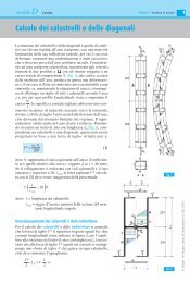
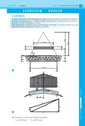
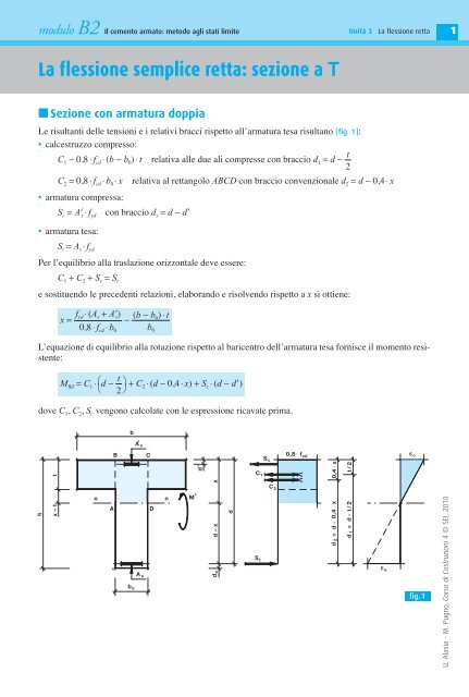
modulo B2 Il cemento armato: metodo agli stati limiteUnità 3 <strong>La</strong> <strong>flessione</strong> <strong>retta</strong>1<strong>La</strong> <strong>flessione</strong> <strong>semplice</strong> <strong>retta</strong>: <strong>sezione</strong> a T■ Sezione <strong>con</strong> <strong>armatura</strong> <strong>doppia</strong>Le risultanti delle tensioni e i relativi bracci rispetto all’<strong>armatura</strong> tesa risultano [fig. 1]:• calcestruzzo compresso:tC 1 − 0,8 ⋅ f cd ⋅ (b − b 0 ) ⋅ t relativa alle due ali compresse <strong>con</strong> braccio d 1 = d −2C 2 = 0,8 ⋅ f cd ⋅ b 0 ⋅ x relativa al <strong>retta</strong>ngolo ABCD <strong>con</strong> braccio <strong>con</strong>venzionale d 2 = d − 0,4 ⋅ x• <strong>armatura</strong> compressa:S c = A s ⋅ f yd <strong>con</strong> braccio d s = d − d• <strong>armatura</strong> tesa:S t = A s ⋅ f ydPer l’equilibrio alla traslazione orizzontale deve essere:C 1 + C 2 + S c = S te sostituendo le precedenti relazioni, elaborando e risolvendo rispetto a x si ottiene:f (b − bx = yd ⋅ (A s + A s )− 0 ) ⋅ t0,8 ⋅ f cd ⋅ b 0 b 0L’equazione di equilibrio alla rotazione rispetto al baricentro dell’<strong>armatura</strong> tesa fornisce il momento resistente:M Rd = C 1 ⋅ ⎛ td − ⎞ + C 2 ⋅(d − 0,4 ⋅ x) + S c ⋅ (d − d)⎝ 2⎠dove C 1 , C 2 , S c vengono calcolate <strong>con</strong> le espressione ricavate prima.tBb,A sCdhx – tnAb oA sDnM +x.,0,8 . f cd e cS cC 1e sx0,4 .t / 2d – xd odS tC 2xd 2 = d - 0,4d 1 = d - t/ 2fig.1U. Alasia - M. Pugno, Corso di Costruzioni 4 © SEI, 2010
modulo B2 Il cemento armato: metodo agli stati limiteUnità 3 <strong>La</strong> <strong>flessione</strong> <strong>retta</strong>2ESERCIZIOSVOLTO<strong>La</strong> <strong>sezione</strong> a T rappresentata nella figura è armata <strong>con</strong> 3 ∅ 18 inferiori e 3 ∅ 8 superiori; calcolare ilmomento resistente sapendo che verrà realizzata <strong>con</strong> calcestruzzo classe C 20/25.400382405042,84nn20127,16 92,842203 1820150Resistenza di calcolo del calcestruzzo: f cd = 11,33 N/mm 2Area dell’<strong>armatura</strong> metallica:A s = 3 ∅ 18 = 763,407 mm 2 ; A s = 3 ∅ 8 = 150,796 mm 2Nell’ipotesi che la <strong>sezione</strong> si comporti come <strong>retta</strong>ngolare <strong>con</strong> base b = 400 mm, la posizione dell’asseneutro risulta:fx = yd ⋅ (A s − A s ) 391 × (763,407 − 150,796)= ≈ 660,07 mm > t = 60 mm0,8 ⋅ f cd ⋅ b 0,8 × 11,33 × 400per cui taglia la nervatura e la sua posizione esatta è:f (b − b 391 × (763,407 − 150,796) (400 − 150) × 50x = yd ⋅ (A s − A s )−0 ) ⋅ t= − ≈ 92,84 mm0,8 ⋅ f cd ⋅ b 0 0,8 × 11,33 × 150150Le risultanti delle tensioni di compressione risultano:C 1 = 0,8 ⋅ f cd ⋅ (b − b 0 ) ⋅ t = 0,8 × 11,33 × (400 − 150) × 50 ≈ 113,300 × 10 3 NC 2 = 0,8 ⋅ f cd ⋅ b 0 ⋅ x = 0,8 × 11,33 × 150 × 92,84 ≈ 126,225 × 10 3 NS c = A s ⋅ f yd = 150,796 × 391 ≈ 58,961 × 10 3 Nb 0Il valore del momento resistente è:M Rd = C 1 ⋅ ⎛ td − ⎞ + C 2 ⋅(d − 0,4 ⋅ x) + S c ⋅ (d − d) = 113,300 × 10 3 × (220 − 25) + 126,225 ×⎝ 2⎠× 10 3 × (220 − 0,4 × 92,84) + 58,961 × (220 − 20) ≈ 56,968 × 10 6 N mm = 56,968 kN mU. Alasia - M. Pugno, Corso di Costruzioni 4 © SEI, 2010
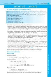
modulo B2 Il cemento armato: metodo agli stati limiteVERIFICAUnità 3 <strong>La</strong> <strong>flessione</strong> <strong>retta</strong>3<strong>La</strong> <strong>sezione</strong> a T rappresentata in figura presenta un’<strong>armatura</strong> <strong>doppia</strong> costituita da 3 ∅ 10 superiori e4 ∅ 18 inferiori, ed è realizzata <strong>con</strong> calcestruzzo classe C 20/25.Calcolare il momento resistente.4003 10nn418200[x ≈ 84,36 mm; M Rd ≈ 226,02 kN m]U. Alasia - M. Pugno, Corso di Costruzioni 4 © SEI, 20103060010030570