Trasmettitore di temperatura analogico per sensori Pt100 ...
Trasmettitore di temperatura analogico per sensori Pt100 ...
Trasmettitore di temperatura analogico per sensori Pt100 ...

You also want an ePaper? Increase the reach of your titles
YUMPU automatically turns print PDFs into web optimized ePapers that Google loves.
Misura <strong>di</strong> <strong>tem<strong>per</strong>atura</strong><br />
elettrica<br />
<strong>Trasmettitore</strong> <strong>di</strong> <strong>tem<strong>per</strong>atura</strong> <strong>analogico</strong><br />
<strong>per</strong> <strong>sensori</strong> <strong>Pt100</strong>, configurabili via PC, con montaggio in testina<br />
Modello T24.10<br />
Applicazioni<br />
■ Costruzione <strong>di</strong> macchine e impianti<br />
■ Industria <strong>di</strong> processo<br />
Caratteristiche <strong>di</strong>stintive<br />
■ Elaborazione del segnale <strong>analogico</strong>, ideale <strong>per</strong> sistemi<br />
multipli<br />
■ Configurazione con Windows PC, simulazione del sensore<br />
non necessaria <strong>per</strong> la configurazione<br />
■ Segnalazione <strong>di</strong> rottura del sensore me<strong>di</strong>ante<br />
NAMUR NE43<br />
■ Software <strong>di</strong> configurazione WIKA_TT in 6 lingue<br />
■ Versione compatta<br />
Descrizione<br />
Il trasmettitore <strong>di</strong> <strong>tem<strong>per</strong>atura</strong> modello T24 è stato progettato<br />
specificatamente <strong>per</strong> <strong>Pt100</strong> con collegamento a 2 o 3 fili e<br />
uscita analogica 4 ... 20 mA (alimentazione loop a 2 fili).<br />
Il T24 combina la velocità <strong>di</strong> risposta <strong>di</strong> un trasmettitore<br />
<strong>analogico</strong> con la flessibilità <strong>di</strong> configurazione tramite<br />
Windows PC. La rapida stabilizzazione del segnale <strong>di</strong> uscita<br />
in corrente dopo l'eccitazione delll'alimentazione consente<br />
l'uso <strong>di</strong> questo trasmettitore in sistemi multiplex.<br />
Grazie alla facilità d'uso del software <strong>di</strong> configurazione<br />
Windows, l'impostazione del campo <strong>di</strong> misura, del tipo <strong>di</strong><br />
sensore e del comportamento in caso <strong>di</strong> rottura del sensore<br />
può essere effettuata in pochi secon<strong>di</strong>. La simulazione del<br />
sensore e le <strong>di</strong>spen<strong>di</strong>ose regolazioni non sono necessarie<br />
<strong>per</strong> questo trasmettitore. Il T24, infatti, può essere configurato<br />
in remoto dalla sala <strong>di</strong> controllo me<strong>di</strong>ante il loop <strong>di</strong> corrente.<br />
Possibili errori <strong>di</strong> misurazione dovuti <strong>per</strong> esempio a una<br />
posizione non corretta della sonda <strong>di</strong> <strong>tem<strong>per</strong>atura</strong> possono<br />
essere compensati me<strong>di</strong>ante la funzione <strong>di</strong> Adattamento.<br />
Scheda tecnica WIKA TE 24.01 ∙ 11/2011<br />
Schede tecniche <strong>di</strong> prodotti analoghi:<br />
Trasmettitori <strong>di</strong> <strong>tem<strong>per</strong>atura</strong> <strong>di</strong>gitali, universalmente programmabili, modello T12.10/30; ve<strong>di</strong> scheda tecnica TE 12.03<br />
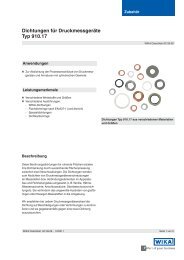
<strong>Trasmettitore</strong> <strong>di</strong> <strong>tem<strong>per</strong>atura</strong> <strong>analogico</strong>,<br />
modello T24.10<br />
Scheda tecnica WIKA TE 24.01<br />
La protezione <strong>di</strong> scrittura e un campo <strong>di</strong> <strong>tem<strong>per</strong>atura</strong><br />
ambiente più ampio completano lo spettro <strong>di</strong> caratteristiche<br />
offerte da questo trasmettitore.<br />
Grazie alla sua affidabilità e flessibilità, il trasmettitore<br />
<strong>di</strong> <strong>tem<strong>per</strong>atura</strong> T24 è idoneo <strong>per</strong> una ampia gamma <strong>di</strong><br />
applicazioni in macchine ed impianti. Sono <strong>di</strong>sponibili<br />
versioni con approvazione ATEX <strong>per</strong> applicazioni<br />
nell‘industria <strong>di</strong> processo.<br />
Come risultato delle sue <strong>di</strong>mensioni estrememente<br />
compatte, questo trasmettitore può essere installato in<br />
qualsiasi testina DIN B.<br />
I trasmettitori vengono forniti in una configurazione base (ve<strong>di</strong><br />
informazioni <strong>per</strong> l'or<strong>di</strong>ne) o secondo specifiche del cliente<br />
entro dati spcificati.<br />
Pagina 1 <strong>di</strong> 7
Specifiche tecniche<br />
Ingresso<br />
Modelli T24.10.1Px, T24.10.2Px <strong>Pt100</strong> secondo DIN EN 60751, 2-fili, 3-fili<br />
Campo <strong>di</strong> misura max. T24.10.1Px: -150 ... +850 °C T24.10.2Px: -200 ... +850 °C<br />
Span <strong>di</strong> misura T24.10.1Px: Minimo 20 K T24.10.2Px: Minimo 50 K<br />
Valore iniziale del campo <strong>di</strong> misura, configurabile T24.10.1Px: -150 ... +150 °C T24.10.2Px: -200 ... +200 °C<br />
Valore finale del campo <strong>di</strong> misura, configurabile in funzione del valore iniziale del campo <strong>di</strong> misura, si veda schema a pagina 4<br />
Configurazione base 3 fili 0 ... 150 °C<br />
Corrente <strong>di</strong> misura ca. 0,5 mA<br />
Cavo <strong>di</strong> collegamento Massima resistenza consentita ± 0,2 K / 10 Ω ciascun filo 1)<br />
30 Ω ciascun filo, trifilare simmetrico<br />
1) Per il collegamento del sensore in una connessione a 3 fili; la resistenza totale del conduttore può essere compensata fino a 20 Ω altrimenti, nel caso <strong>di</strong> connessione a 2 fili, la resistenza<br />
del conduttore viene registrata come un errore.<br />
Uscita analogica<br />
Uscita analogica, configurabile lineare alla <strong>tem<strong>per</strong>atura</strong> secondo IEC 60751<br />
4 … 20 mA, circuito a 2 fili<br />
Deviazione <strong>di</strong> misura conforme a DIN EN 60770, 23 °C ± 5 K ± 0,2 % 2)<br />
Linearizzazione lineare alla <strong>tem<strong>per</strong>atura</strong> secondo DIN EN 60751<br />
Errore <strong>di</strong> linearizzazione ± 0,1 % 3)<br />
Coefficiente <strong>di</strong> <strong>tem<strong>per</strong>atura</strong> TK Punto zero<br />
± 0,1 % / 10 KTa o<br />
Span<br />
4) ± 0,15 K / 10 KTa<br />
± 0,15 % / 10 KTa<br />
Tempo <strong>di</strong> salita t90 < 1 ms<br />
Ritardo all'accensione, elettrico < 10 ms<br />
Segnalazione Burnout sensore configurabile:<br />
■ NAMUR limite inferiore<br />
■ NAMUR limite su<strong>per</strong>iore<br />
< 3,6 mA (tipico 3 mA)<br />
> 21.0 mA (tipico 23 mA)<br />
Cortocircuito sensore non configurabile, in generale:<br />
■ NAMUR limite inferiore < 3,6 mA (tipico 3 mA) 5)<br />
Carico RA RA ≤ (UB - 10 V) / 0,022 A con RA in Ω e UB in V<br />
Effetto del carico ± 0,05 % / 100 Ω<br />
Effetto dell'alimentazione ± 0,025 % / V<br />
2) Per span <strong>di</strong> misura inferiori a 50 K: + 0,1 K, <strong>per</strong> span <strong>di</strong> misura su<strong>per</strong>iori a 550 K; + 0,1 %<br />
3) ± 0,2 % <strong>per</strong> campi <strong>di</strong> misura con limite inferiore al <strong>di</strong> sotto <strong>di</strong> 0 °C o fondo scala maggiori <strong>di</strong> 800 K<br />
4) Applicabile il valore maggiore; entro tra il campo standard <strong>di</strong> <strong>tem<strong>per</strong>atura</strong> ambiente -40 °C ≤ Ta ≤ +85 °C, con<br />
campo esteso <strong>di</strong> <strong>tem<strong>per</strong>atura</strong> ambiente, si applica il valore doppio al <strong>di</strong> fuori del campo standard<br />
5) Valore <strong>di</strong> <strong>tem<strong>per</strong>atura</strong>, in caso <strong>di</strong> corto circuito tra il conduttore n. 2 e il n. 3 (funzionamento del sensore con collegamento a 2 fili)<br />
I valori in % si riferiscono allo span <strong>di</strong> misura<br />
Ta Tem<strong>per</strong>atura ambiente<br />
UB Tensione <strong>di</strong> alimentazione del loop, ve<strong>di</strong> alimentazione<br />
Omologazioni<br />
Germanischer Lloyd (modello T24.10.xxx-G) Certificato <strong>di</strong> omologazione n. 47183-03 HH<br />
Categoria ambientale D, F, H, EMC1<br />
Gosstandart Certificato <strong>di</strong> omologazione DE.C.32.001.A n. 15279<br />
Pagina 2 <strong>di</strong> 7 Scheda tecnica WIKA TE 24.01 ∙ 11/2011
Protezione antideflagrante, alimentazione<br />
Modello Omologazioni Tem<strong>per</strong>atura ambiente/<strong>di</strong><br />
stoccaggio consentita (conforme<br />
alle classi <strong>di</strong> <strong>tem<strong>per</strong>atura</strong>)<br />
Valori <strong>di</strong> sicurezza max. <strong>per</strong><br />
Sensore Loop <strong>di</strong> corrente<br />
(collegamenti da 1 a 3) (collegamenti ±)<br />
IIC: Co = 20 µF<br />
Lo = 10 mH<br />
Uoc = DC 6,4 V<br />
Isc = 42,6 mA<br />
Pmax = 37,1 mW<br />
Ca = 20 µF<br />
La = 10 mH<br />
Uoc = DC 6,4 V<br />
Isc = 21,1 mA<br />
Pmax = 34 mW<br />
Ca = 20 µF<br />
La = 10 mH<br />
Uo = DC 5,4 V<br />
Io = 0,51 mA<br />
Co = 200 µF<br />
Lo = 1000 mH<br />
Alimentazione<br />
UB (DC) 1)<br />
T24.10.xx0 senza -40 ... +85 °C - - 10 ... 36 V<br />
T24.10.xx2 Certificato CE prove <strong>di</strong> tipo:<br />
-40 ... +85 °C a T4<br />
Uo = DC 6,4 V<br />
Ui = DC 30 V 10 ... 30 V<br />
DMT02 ATEX E 025 X<br />
-40 ... +75 °C a T5<br />
Io = 42,6 mA<br />
Ii =120 mA<br />
II 1G EEx ia IIB/IIC T4/T5/T6<br />
A sicurezza intrinseca conforme alla<br />
Direttiva 94/9/CE (ATEX)<br />
-40 ... +60 °C a T6<br />
Po = 37,1 mW<br />
IIB: Co = 500 µF<br />
Lo = 50 mH<br />
Pi = 800 mW<br />
Ci = 6,2 nF<br />
Li = 110 µH<br />
T24.10.xx6 CSA approvazione 105000-6<br />
Classe I, <strong>di</strong>visione 1, gruppi A, B, C, D<br />
T24.10.xx8 Approvazione FM 2475796<br />
Classe I, <strong>di</strong>visione 1, gruppi A, B, C, D<br />
T24.10.xx9 II 3 G Ex nA IIC T4…T6<br />
II 3 G Ex nL IIC T4…T6<br />
II 3 G Ex ic IIC T4…T6<br />
max. +85 °C a T4<br />
max. +75 °C a T5<br />
max. +60 °C a T6<br />
-40 ... +85 °C a T4<br />
-40 ... +75 °C a T5<br />
-40 ... +60 °C a T6<br />
-40 ... +85 °C a T4<br />
-40 ... +65 °C a T5<br />
-40 ... +50 °C a T6<br />
1) Ingresso dell'alimentazione protetto dalla polarità inversa; carico RA ≤ (UB - 10 V) / 0,022 A con RA in Ω e UB in V<br />
Con<strong>di</strong>zioni ambientali<br />
2) -40 ... +105 °C solo senza protezione antideflagrante<br />
Custo<strong>di</strong>a<br />
Materiale Plastica, PBT, fibra <strong>di</strong> vetro rinforzata<br />
Grado <strong>di</strong> protezione Custo<strong>di</strong>a<br />
IP 66/IP 67 secondo IEC 60529/EN 60529<br />
Collegamenti dei terminali IP 00 conforme a IEC 60529/EN 60529<br />
Sezione trasversali dei conduttori 0,14 ... 1,5 mm²<br />
Peso ca. 0,04 kg<br />
Dimensioni ve<strong>di</strong> <strong>di</strong>mensioni<br />
Varie<br />
Umax = DC 30 V<br />
Imax = 120 mA<br />
Pmax = 800 mW<br />
Ci = 6,2 nF<br />
Li = 110 µH<br />
Umax = DC 30 V<br />
Imax = 120 mA<br />
Pmax = 800 mW<br />
Ci = 6,2 nF<br />
Li = 110 µH<br />
Ui = DC 36 V<br />
Ci = 10 nF<br />
Li = 110 µH<br />
10 ... 30 V<br />
10 ... 30 V<br />
10 ... 36 V<br />
Campo <strong>di</strong> <strong>tem<strong>per</strong>atura</strong> ambiente e <strong>di</strong> stoccaggio Standard: -40 ... +85 °C<br />
Opzionale: -40 ... +105 °C 2)<br />
Classe climatica conforme a DIN EN 60654-1 Cx (-40 ... +85 °C, 5 ... 95 % <strong>di</strong> umi<strong>di</strong>tà relativa dell'aria)<br />
Massima umi<strong>di</strong>tà consentita secondo DIN EN 60068-2-30 var. 2 100 % umi<strong>di</strong>tà relativa, condensazione consentita<br />
Vibrazioni conformi a DIN EN 60068-2-6 10 ... 2000 Hz, 10 g<br />
Shock DIN EN 60068-2-27<br />
Umi<strong>di</strong>tà salina DIN EN 60068-2-11<br />
Compatibilità elettromagnetica (EMC) 2004/108/EC, EN 61326 (gruppo 1, classe A) emissioni e immunità alle<br />
interferenze (applicazione industriale)<br />
Unità <strong>di</strong> <strong>tem<strong>per</strong>atura</strong> configurable: °C, °F, K<br />
Termoresistenza Possono essere collegati <strong>sensori</strong> <strong>di</strong> resistenza lineari<br />
Attacco del sensore configurabile: a 2 o 3 fili<br />
compensazione configurabile del cavo <strong>di</strong> connessione con collegamento a 2 fili<br />
Dati informativi Tag nr., descrizione e messaggio <strong>per</strong> la configurazione possono essere memorizzati nel trasmettitore<br />
Dati <strong>di</strong> configurazione e calibrazione memorizzazione <strong>per</strong>manente in EEPROM<br />
Scheda tecnica WIKA TE 24.01 ∙ 11/2011<br />
Pagina 3 <strong>di</strong> 7
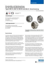
Diagramma <strong>di</strong> carico<br />
Il carico consentito <strong>di</strong>pende dalla tensione <strong>di</strong> alimentazione<br />
del loop.<br />
Carico RA in Ω<br />
Combinazioni possibili del valore iniziale / del valore finale del campo <strong>di</strong> misura<br />
Il valore su<strong>per</strong>iore del campo <strong>di</strong> misura <strong>di</strong>pende dal corrispondente valore iniziale. Per una panoramica <strong>di</strong> questa<br />
corrispondenza, vedere i grafici in<strong>di</strong>cati, come ad esempio <strong>per</strong> intervalli <strong>di</strong> 50 °C.<br />
Il software <strong>di</strong> configurazione verifica il campo <strong>di</strong> misura richiesto e accetta solo i valori consentiti.<br />
I valori interme<strong>di</strong> sono configurabili; il minimo incremento è 0,1 °C.<br />
Schema dei campi <strong>di</strong> misura, modello T24.10.1Px<br />
Campo <strong>di</strong> valore finale possibile del campo <strong>di</strong> misura in °C<br />
-200 -100 0 +100 +200 +300 +400 +500 +600 +700 +800<br />
-150 °C<br />
-100 °C<br />
-50 °C<br />
-40 °C<br />
0 °C<br />
+10 °C<br />
+20 °C<br />
+50 °C<br />
Valore iniziale del<br />
campo <strong>di</strong> misura<br />
+100 °C<br />
+150 °C<br />
Schema dei campi <strong>di</strong> misura Modello T 24.10.2Px<br />
Campo <strong>di</strong> valore finale possibile del campo <strong>di</strong> misura in °C<br />
-200 -100 0 +100 +200 +300 +400 +500 +600 +700 +800<br />
-200 °C<br />
-150 °C<br />
-100 °C<br />
-50 °C<br />
0 °C<br />
+50 °C<br />
+100 °C<br />
+150 °C<br />
+200 °C<br />
Valore iniziale del<br />
campo <strong>di</strong> misura<br />
Tensione UB in V<br />
(EEx ia) (EEx nL/nA)<br />
2363156,01<br />
Numero <strong>di</strong> fili:<br />
2363156.01<br />
Campo <strong>di</strong> misura in °C<br />
Minimo Massimo<br />
-150 ... +380 -150 ... +850<br />
-100 ... +180 -100 ... +850<br />
-50 ... -20 -50 ... +850<br />
-40 ... -20 -40 ... +850<br />
0 ... +20 0 ... +850<br />
+10 ... +30 +10 ... +850<br />
+20 ... +50 +20 ... +850<br />
+50 ... +230 +50 ... +850<br />
+100 ... +530 +100 ... +850<br />
+150 ... +830 +150 ... +850<br />
Campo <strong>di</strong> misura in °C<br />
Minimo Massimo<br />
-200 ... +350 -200 ... +850<br />
-150 ... +150 -150 ... +850<br />
-100 ... -50 -100 ... +850<br />
-50 ... 0 -50 ... +850<br />
0 ... +50 0 ... +850<br />
+50 ... +100 +50 ... +850<br />
+100 ... +150 +100 ... +850<br />
+150 ... +450 +150 ... +850<br />
+200 ... +750 +200 ... +850<br />
Pagina 4 <strong>di</strong> 7 Scheda tecnica WIKA TE 24.01 ∙ 11/2011
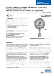
Dimensioni in mm<br />
Assegnazione collegamenti<br />
Termoresistenza /<br />
Termoresistenza<br />
3 fili 2 fili<br />
Collegamento dell'unità <strong>di</strong> programmazione PU-448<br />
Connessione PU-448 ↔ trasmettitore <strong>di</strong> <strong>tem<strong>per</strong>atura</strong><br />
(opzione: connettore rapido magWIK)<br />
Scheda tecnica WIKA TE 24.01 ∙ 11/2011<br />
Ingresso Loop 4 ... 20 mA<br />
T24,10<br />
3214338.04<br />
2363092.01<br />
2363122.01<br />
Pagina 5 <strong>di</strong> 7
Accessori<br />
Set <strong>di</strong> configurazione<br />
Modello Caratteristiche <strong>di</strong>stintive N. d'or<strong>di</strong>nazione<br />
Unità <strong>di</strong> programmazione<br />
Modello PU-448<br />
Connettore rapido magnetico<br />
magWIK<br />
Software<br />
■ Facile da usare<br />
■ Display <strong>di</strong> stato a LED<br />
■ Versione compatta<br />
■ Non è ora necessaria ulteriore alimentazione sia <strong>per</strong> l'unità <strong>di</strong><br />
programmazione che <strong>per</strong> il trasmettitore<br />
■ È possibile misurare la corrente <strong>di</strong> circuito del trasmettitore <strong>di</strong> <strong>tem<strong>per</strong>atura</strong><br />
modello T24<br />
■ Sostituisce i connettori a coccodrillo ed i terminali HART ®<br />
■ Connessione elettrica rapida, sicura ed affidabile<br />
■ Per tutte le attività <strong>di</strong> configurazione e calibrazione<br />
Software <strong>di</strong> configurazione WIKA_TT (multilingua) scaricabile gratuitamente dal sito www.wika.it<br />
11606304<br />
11604328<br />
Pagina 6 <strong>di</strong> 7 Scheda tecnica WIKA TE 24.01 ∙ 11/2011
12/2011 I based on 11/2011 GB<br />
Accessori <strong>di</strong> montaggio<br />
Custo<strong>di</strong>a da campo<br />
Adattatore, plastica / acciaio inox Adattatore, acciaio galvanizzato<br />
Accessori (si prega <strong>di</strong> or<strong>di</strong>nare separatamente) N. d'or<strong>di</strong>nazione<br />
Custo<strong>di</strong>a da campo, plastica (ABS), IP 65, <strong>per</strong> montaggio <strong>di</strong> un trasmettitore<br />
nella testina, <strong>tem<strong>per</strong>atura</strong> ambiente consentita: -40 ... +80 °C, 82 x 80 x 55 mm<br />
(L x L x A), con due pressacavi filettati M16 x 1,5<br />
3301732<br />
Adattatore, plastica / acciaio inox, <strong>per</strong> montaggio su guida DIN 3593789<br />
Adattatore in acciaio galvanizzato, <strong>per</strong> montaggio su guida DIN 3619851<br />
© 2003 WIKA Alexander Wiegand SE & Co. KG, tutti i <strong>di</strong>ritti riservati.<br />
Le specifiche tecniche riportate in questo documento rappresentano lo stato dell'arte al momento della pubblicazione.<br />
Ci riserviamo il <strong>di</strong>ritto <strong>di</strong> apportare mo<strong>di</strong>fiche alle specifiche tecniche ed ai materiali.<br />
Scheda tecnica WIKA TE 24.01 ∙ 11/2011<br />
3301732.01<br />
3224741.01<br />
WIKA Italia Srl & C. Sas<br />
Via Marconi, 8<br />
20010 Arese (Milano)<br />
Tel. (+39) 02-93861-1<br />
Fax: (+39) 02-93861-74<br />
E-Mail: info@wika.it<br />
www.wika.it<br />
3222438.01<br />
Pagina 7 <strong>di</strong> 7