aero2 Pneumatic Actuator - SVF Flow Controls, Inc.
aero2 Pneumatic Actuator - SVF Flow Controls, Inc.
aero2 Pneumatic Actuator - SVF Flow Controls, Inc.

You also want an ePaper? Increase the reach of your titles
YUMPU automatically turns print PDFs into web optimized ePapers that Google loves.
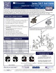
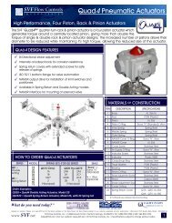
The pneumatic rack & pinion actuator is manufactured using the latest materialsand methods to provide dependable and smooth operation in demandingprocess control conditions.<strong>aero2</strong> DESIGN FEATURESHard Anodized aluminum housing“Versa-View” Continuous mechanical positionindicatorNickel Plated Alloy drive shaftISO/NAMUR design for universal mounting andaccessory attachmentBi-Directional Stroke Adjustment1/4” NPT air inlet manifoldSV F <strong>Flow</strong> <strong>Controls</strong>I N C O R P O R A T E DScan the barcode with your Smart-Phone app and view the latestpublication of this document<strong>Actuator</strong> is designed for 120 psi supply air pressureOptional 304 SS and 316 SS material available -Consult <strong>SVF</strong><strong>aero2</strong> <strong>Pneumatic</strong> <strong>Actuator</strong>High Performance Compact <strong>Pneumatic</strong> <strong>Actuator</strong>saero 2MATERIALS OF CONSTRUCTIONITEM DESCRIPTION MATERIALS SPECIFICATIONS123456789101112131415161718192021222324252627Indicator Cap ScrewPosition IndicatorPinion Snap RingThrust WasherThrust BearingBodyPiston GuideO-Ring (Pinion Top)Bearing (Pinion Top)Inside WasherStroke Adjustment StopPinion (Drive Shaft)Bearing (Pinion Bottom)O-Ring (Pinion Bottom)Spring (Cartridge)Bearing (Piston)O-Ring (Piston)PistonPlugO-Ring (Adjust Screw)Stop Nut (Adjust Screw)Adjust ScrewStop ScrewNut (Stop Screw)O-Ring (End Cap)End CapEnd Cap ScrewWhat do you need today? TMPlastic/Stainless SteelPlastic (ABS)Stainless Steel 300 SeriesStainless Steel 300 SeriesPolyoxymethylene (Delrin ® )Extruded Aluminum AlloyPolyoxymethylene (Delrin ® )Buna “N” (standard), Viton ®Polyoxymethylene (Delrin ® )Polyoxymethylene (Delrin ® )Alloy SteelNickel Plated Alloy SteelPolyoxymethylene (Delrin ® )Buna “N” (standard), Viton ®Spring Steel (Corrosion Resistant)Polyoxymethylene (Delrin ® )Buna “N” (standard), Viton ®AluminumNBRBuna “N” (standard), Viton ®Stainless Steel 300 SeriesStainless Steel 300 SeriesStainless Steel 300 SeriesStainless Steel 300 SeriesBuna “N” (standard), Viton ®AluminumStainless Steel 300 SeriesBI-DIRECTIONAL STROKE ADJUSTMENTaero 2 actuators feature bi-directionalpinion travel stops. These stops allow fortrue +/-5 o for valve travel adjustmentto ensure precise positioning in all flowcontrol services. The aero 2 travel stopsare designed to absorb the maximumrated torque of the actuator and themaximum impact loads associated withthe recommended stroke speed.UALITY FLOWSTHROUGH USSpecifications subject to change. Please visit www.<strong>SVF</strong>.net for the latest updates on this Data Sheet. All Data Sheets posted on our website supersede all prior publications • [Document #<strong>SVF</strong>_<strong>aero2</strong>_Data_Sheet • 08/27/2012www.<strong>SVF</strong>.net<strong>SVF</strong> <strong>Flow</strong> <strong>Controls</strong>, <strong>Inc</strong>. • 13560 Larwin Circle • Santa Fe Springs, CA 90670 • Tel: 1.800.783.7836 • FAX: 562.802.3114Sales@<strong>SVF</strong>.net • Visit our website: www.<strong>SVF</strong>.net • © <strong>SVF</strong> <strong>Flow</strong> <strong>Controls</strong>, <strong>Inc</strong>. • Specifications subject to change without notice1
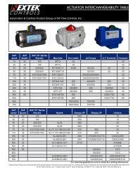
SV F <strong>Flow</strong> <strong>Controls</strong>I N C O R P O R A T E D<strong>aero2</strong> <strong>Pneumatic</strong> <strong>Actuator</strong>High Performance Compact <strong>Pneumatic</strong> <strong>Actuator</strong>s<strong>aero2</strong> DIMENSIONAL TABLE (INCHES)Model1020355075110160255400500550600650700A1.121.181.421.651.811.972.262.662.953.434.064.455.125.79B1.441.631.852.092.242.302.522.933.033.434.064.455.125.79C3.153.624.234.705.075.396.026.897.548.549.8411.2212.5514.01<strong>aero2</strong> - WEIGHTSD4.805.796.617.248.0410.3110.5511.6515.3518.0320.7922.2023.7027.80E3.153.153.153.153.153.153.153.153.153.155.125.125.125.12F1.181.181.181.181.181.181.181.181.181.181.181.181.181.18GF03/1.42F03/1.42F05/1.97F05/1.97F05/1.97F05/1.97F07/2.75F07/2.75F10/4.02F10/4.02----HF05/1.97F05/1.97F07/2.76F07/2.76F07/2.76F07/2.76F10/4.02F10/4.02F12/4.92F12/4.92F14/5.51F14/5.51F16/6.49F16/6.49J#10-32UNF#10-32UNF1/4”-20UNC1/4”-20UNC1/4”-20UNC1/4”-20UNC5/16”-18UNC5/16”-18UNC3/8”-16UNC3/8”-16UNC----K1/4”-20UNC1/4”-20UNC5/16”-18UNC5/16”-18UNC5/16”-18UNC5/16”-18UNC3/8”-16UNC3/8”-16UNC1/2”-13UNC1/2”-13UNC5/8”-11UNC5/8”-11UNC3/4”-10UNC3/4”-10UNCaero 2L sq L N (Depth) N0.43 0.550.43 0.550.55 0.710.55 0.710.67 0.830.67 0.830.87 1.020.87 1.021.06 1.221.06 1.221.42 1.571.42 1.571.81 1.971.81 1.97Model1020355075110160255400500550600650700lbs2346710131925367076106163A2Dkg11223459142231354874lbs-346712142229447885135216A2Skg-122356101626353961980.787” for A10 ~ A5001.181” for A550 ~ A700HOW TO ORDER <strong>aero2</strong> ACTUATORSSeriesA2D = Double ActingA2S = Spring ReturnA2DNI =Double Acting withNickel Infused AluminumHousingA2SNI =Spring Return withNickel Infused AluminumHousingSpecifications subject to change. Please visit www.<strong>SVF</strong>.net for the latest updates on this Data Sheet. All Data Sheets posted on our website supersede all prior publications • [Document #<strong>SVF</strong>_<strong>aero2</strong>_Data_Sheet • 08/27/2012www.<strong>SVF</strong>.netModel10t20355075110160255400500550600650700SpringsBlank =Double Acting5678910*1112(*10 Springsare standard)SealsBlank =Buna “N”(standard)V =Viton ®(optional)Options180 =180 o operation(Double ActingOnly)tSeries A2D-10 is onlyavailable as a DoubleActing Model and notavailable with Viton or the180 o operation option.Order Example for Model 20 Double Acting, 180 o Operation: = A2D-20-180A2D 20 180Order Example for Model 20 Spring Return, with 10 Springs: = A2S-20-10-VA2S 20 10 V (optional Viton ® Seals)<strong>SVF</strong> <strong>Flow</strong> <strong>Controls</strong>, <strong>Inc</strong>. • 13560 Larwin Circle • Santa Fe Springs, CA 90670 • Tel: 1.800.783.7836 • FAX: 562.802.3114Sales@<strong>SVF</strong>.net • Visit our website: www.<strong>SVF</strong>.net • © <strong>SVF</strong> <strong>Flow</strong> <strong>Controls</strong>, <strong>Inc</strong>. • Specifications subject to change without notice2
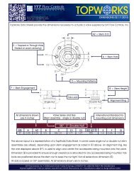
SV F <strong>Flow</strong> <strong>Controls</strong>I N C O R P O R A T E D<strong>aero2</strong> <strong>Pneumatic</strong> <strong>Actuator</strong>High Performance Compact <strong>Pneumatic</strong> <strong>Actuator</strong>saero 2 3<strong>aero2</strong> SPRING RETURN OUTPUT TORQUES (in-lbf)OUTPUT AIR TO SPRINGContinued on next page>>SUPPLY PRESSURE (psig)>> 40 50 60 70 80 90 100 SPRING OUTPUTMODELA2S-20A2S-35A2S-50A2S-75A2S-110A2S-160A2S-255SPRINGQTY56789101112567891011125678910111256789101112567891011125678910111256789101112Specifications subject to change. Please visit www.<strong>SVF</strong>.net for the latest updates on this Data Sheet. All Data Sheets posted on our website supersede all prior publications • [Document #<strong>SVF</strong>_<strong>aero2</strong>_Data_Sheet • 08/27/2012www.<strong>SVF</strong>.net0 oSTART554839111988414112110122719616632227723149743537471261050990 oEND372413755535103744715711267214148803252291334533051480 oSTART77706153441531381271111971761551333172852522214504033553196876225594941,00089378768190 oEND58463420811695735215812899692441961511033382691971285084073082087295744102550 oSTART9249084766860204191179167154132702512322111921744284003713423132846125695264844413999218628057476896311,3581,2631,1671,07197688090 oEND78675544332113715213311495752352081821551291023643212792371951525114493853232601977606705804904003061,1159768286895414020 oSTART1201131059891832422292182061951841713213032842662462312135084814544264003733457256856466065665254861,0081,0359809278728187641,6081,5191,4291,3401,2511,1611,07290 oEND897867574636205187169151133115972802562312061811571324343953553162762371986125534954363773182609088247406565694874061,3401,2021,0729348046665360 oSTART1401331261191122672552442342223523353183012845605345084834567997617236856471,2031,1521,1001,0489971,7701,6851,6001,5141,429<strong>SVF</strong> <strong>Flow</strong> <strong>Controls</strong>, <strong>Inc</strong>. • 13560 Larwin Circle • Santa Fe Springs, CA 90670 • Tel: 1.800.783.7836 • FAX: 562.802.3114Sales@<strong>SVF</strong>.net • Visit our website: www.<strong>SVF</strong>.net • © <strong>SVF</strong> <strong>Flow</strong> <strong>Controls</strong>, <strong>Inc</strong>. • Specifications subject to change without notice90 oEND1141049484742202031861691523012782542312074664293913533166555995434874329748948117336561,4291,2981,1741,0439190 oSTART1601531461393153042932832714184023863693536636386135885639479118748378001,4191,3701,3201,2701,2212,1002,0181,9361,8541,77290 oEND132122113952692532362202043693473243012785725365004644288087557006475931,1981,1221,0419668921,7721,6451,5261,3991,2800 oSTART1721663413303204514354197156916671,0229869501,5351,4861,4392,2642,1842,10590 oEND1401302862702543913693466055705368538017491,2641,1911,1191,8651,7421,62690 oSTART5566778798109120131921111291481661852032221281541792052312562823082042442853263674074484893043654264875486086697304365236106977848719581,0456988329711,1101,2491,3871,5301,6650 oEND384552606775829061728597109121133145931121311491681872052241401681962242522803083362072482893313724134544962803363924485045606166724625556477408329251,0171,110
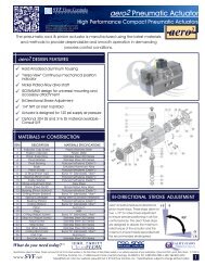
SV F <strong>Flow</strong> <strong>Controls</strong>I N C O R P O R A T E D<strong>aero2</strong> <strong>Pneumatic</strong> <strong>Actuator</strong>High Performance Compact <strong>Pneumatic</strong> <strong>Actuator</strong>s<strong>aero2</strong> SPRING RETURN OUTPUT TORQUES (in-lbf)aero 2OUTPUT AIR TO SPRING 40 50 60 70 80 90 100 SPRING OUTPUTMODELA2S-400A2S-500A2S-550A2S-600A2S-650A2S-700SPRINGQTY5678910111256789101112567891011125678910111256789101112567891011120 oSTART1,2461,0829161,8771,6091,3323,2282,8392,4513,8013,2652,7285,3734,5783,7738,7867,6956,61290 oEND8235733241,2128053982,1641,5639622,7742,0351,2953,9772,8951,8226,5765,0503,5140 oSTART1,7371,5661,3921,2182,6402,3592,0691,7894,4574,0513,6453,2395,3274,7674,2063,6457,5716,7395,8985,06612,16311,0229,8918,75090 oEND1,2961,0357735121,9431,5181,0936673,3452,7172,0881,4604,2543,4812,7071,9346,1114,9793,8582,7279,8528,2576,6525,0570 oSTART2,3462,1922,0351,8781,7131,5573,5923,3403,0792,8262,5662,3135,9575,5925,2274,8614,4964,1317,2276,7236,2185,7145,2094,70510,3329,5848,8278,0797,3236,57516,28915,26314,24513,21912,19311,16790 oEND1,9481,7131,4781,2441,0097652,9662,5832,2001,8181,4351,0524,9574,3923,8273,2612,6962,1316,2625,5664,8704,1743,4792,7839,0188,0016,9925,9754,9573,94814,21012,77511,3329,8978,4537,0180 oSTART2,7782,6312,4852,3312,1852,0391,8924,2564,0123,7773,5333,2973,0622,8187,0416,7006,3596,0185,6775,3364,9958,5528,0817,6107,1396,6686,1695,72612,23911,53310,83410,1289,4298,7318,02419,25618,30617,34816,38915,43114,47313,52390 oEND2,3312,1121,8921,6731,4461,2261,0073,5493,1922,0222,4772,1201,7711,4135,9215,3934,8654,3373,8093,2812,7537,4726,8226,1725,5234,8734,2233,57410,7619,8198,8697,9196,9766,0265,07616,93415,58514,24512,89711,55710,2098,8690 oSTART3,0632,9162,7772,6382,4984,6804,4484,2233,9993,7677,7897,4647,1396,8146,4909,4138,9658,5168,0687,61913,45112,77812,11311,44810,77521,28620,37419,46118,54817,64390 oEND2,4982,2902,0731,8641,6553,7823,4423,1022,7692,4296,3665,8635,3604,8584,3558,0447,4266,8076,1885,56911,57910,6749,7778,8727,96718,33217,04815,77114,48713,2110 oSTART3,6243,4833,3483,2143,0805,5565,3325,1164,9004,6769,1808,8678,5548,2407,92711,16410,73110,2999,8669,43415,98915,34014,69914,05713,40825,10924,22923,34922,46921,59790 oEND3,0802,8792,6702,4682,2674,6914,3634,0343,7143,3867,8087,3236,8386,3545,8699,8449,2478,6518,0547,45714,18413,31212,44611,57410,70122,26021,02319,79218,55417,3240 oSTART3,9063,7763,6455,9865,7765,5599,9369,6329,32712,03811,61711,19717,22016,59615,96627,15626,30025,45290 oEND3,2473,0512,8554,9354,6244,3058,2697,7987,32710,4369,8569,27615,03114,18313,33523,69922,49621,30090 oSTART1,1431,3701,5981,8261,0542,2832,5102,7411,8442,2122,5812,9493,3213,6914,0564,4222,7373,2873,8344,3804,9275,4736,0206,5663,3634,0364,7085,3816,0536,7267,3998,0714,9025,8856,8617,8448,8289,80310,78711,7716,9618,3499,74411,13212,52713,91415,31016,6970 oEND7599081,0591,2111,3701,5221,6731,8241,2361,4831,7301,9772,2252,4722,7192,9661,7742,1272,4802,8333,1863,5403,8934,2462,4302,9173,4053,8934,3804,8685,3565,8433,6324,3555,0875,8106,5417,2647,9878,7194,9525,9446,9287,9208,9129,90410,89611,880ACTUATOR MODELA2D-10A2D-20A2D-35A2D-50A2D-75A2D-110A2D-160405597178245383551808Supply Pressure (psig)60 8085 115146 195267 356368 490574 766827 1,1031,211 1,615DOUBLE ACTING TORQUE (in-lbf)1001422444466139571,3782,019ACTUATOR MODELA2D-255A2D-400A2D-500A2D-550A2D-600A2D-650A2D-700401,2252,0883,2495,1986,4979,39814,282Supply Pressure (psig)60 801,833 2,4503,133 4,1774,873 6,4977,797 10,3969,746 12,99514,097 18,79621,430 28,5651003,0635,2218,12212,99516,24323,49535,712Specifications subject to change. Please visit www.<strong>SVF</strong>.net for the latest updates on this Data Sheet. All Data Sheets posted on our website supersede all prior publications • [Document #<strong>SVF</strong>_<strong>aero2</strong>_Data_Sheet • 08/27/2012www.<strong>SVF</strong>.net<strong>SVF</strong> <strong>Flow</strong> <strong>Controls</strong>, <strong>Inc</strong>. • 13560 Larwin Circle • Santa Fe Springs, CA 90670 • Tel: 1.800.783.7836 • FAX: 562.802.3114Sales@<strong>SVF</strong>.net • Visit our website: www.<strong>SVF</strong>.net • © <strong>SVF</strong> <strong>Flow</strong> <strong>Controls</strong>, <strong>Inc</strong>. • Specifications subject to change without notice4
SV F <strong>Flow</strong> <strong>Controls</strong>I N C O R P O R A T E D<strong>aero2</strong> <strong>Pneumatic</strong> <strong>Actuator</strong>High Performance Compact <strong>Pneumatic</strong> <strong>Actuator</strong>s<strong>aero2</strong> ACTUATOR SIZING GUIDEaero 2Selecting the correct <strong>Actuator</strong> (Sizing)The output torques for each actuator model are listed in the Torque Tables (Pages 3 and 4).These values do not include a safety factor. For best results we recommend selecting an actuatormodel with a minimum output torque that is greater than the highest operating torque of the valve to beactuated, plus 10%.Example for Double Acting (DA) <strong>Actuator</strong> Sizing:Published Valve Torque:Air Supply:<strong>aero2</strong> Model:300 in-lbs (plus 10% safety factor = 330 in-lbf)80 psigA2D-35The A2D-35 has the output torque value of 356 in-lbf @ 80 psig.Example for Spring Return (SR) <strong>Actuator</strong> Sizing:Published Valve Torque:Air Supply:<strong>aero2</strong> Model:300 in-lbs (plus 10% safety factor = 330 in-lbf)80 psigA2S-110 (10 Springs - Standard)The A2S-110 has the following output torque values @ 80 psig:Air End:543 in-lbfSpring End:413 in-lbfSizing Safety FactorsMedia and other conditions can effect the operating torque of a valve.Following is a list of common Safety Factors.MEDIASAFETY FACTORBasic Value 1.0Liquid, clean (particle free) 1.0Gas, clean and wet (saturated steam) 1.0Gas, dry (superheated steam) 1.3Gas, dirty (natural gas) 1.5Oxygen, Chlorine 1.5Liquid, dirty (slurry), raw water 1.8Paste/Paint 1.8Specifications subject to change. Please visit www.<strong>SVF</strong>.net for the latest updates on this Data Sheet. All Data Sheets posted on our website supersede all prior publications • [Document #<strong>SVF</strong>_<strong>aero2</strong>_Data_Sheet • 08/27/2012www.<strong>SVF</strong>.net<strong>SVF</strong> <strong>Flow</strong> <strong>Controls</strong>, <strong>Inc</strong>. • 13560 Larwin Circle • Santa Fe Springs, CA 90670 • Tel: 1.800.783.7836 • FAX: 562.802.3114Sales@<strong>SVF</strong>.net • Visit our website: www.<strong>SVF</strong>.net • © <strong>SVF</strong> <strong>Flow</strong> <strong>Controls</strong>, <strong>Inc</strong>. • Specifications subject to change without notice5
NOTES:
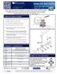
SV F <strong>Flow</strong> <strong>Controls</strong>I N C O R P O R A T E DQuad4 <strong>Pneumatic</strong> <strong>Actuator</strong>sHigh Performance, Four Piston, Rack & Pinion <strong>Actuator</strong>sThe <strong>SVF</strong> “Quad4 TM ” quarter-turn rack & pinion actuator is a four piston actuator whichgenerates torque around a centrally located pinion, giving more than double thetorque of single & double rack & pinion actuator designs. The increased number of pistons allows theirdiameter to be reduced while maintaining it’s high torque, allowing the reduced size of the actuator.QUAD4 DESIGN FEATURESBi-Directional stroke adjustmentInternally anodized body for corrosion resistanceSpring return covers with extended screws for saferelease of springsISO 5211 bottom flange for valve automationNAMUR output drive for installation of limit switches andpositionersAvailable in Spring Return and Double Acting modelsNAMUR interface for mounting of solenoid valveMATERIALS OF CONSTRUCTIONHOW TO ORDER QUAD4 ACTUATORSSERIESQD =DoubleActingQS =Spring ReturnMODEL1520253035456075What do you need today? TMSPRING SETS (FOR QS SERIES)QS15 (Only):1A1B1B2*2(*Standard)QS20 thru QS75:2AB 2A32A 2C*2A2B 2C32B 3(*Standard)SEALS“Blank” =Buna “N”(Standard)V = Viton(Optional)Order Examples:QD20 = Quad4 Double Acting <strong>Actuator</strong>, Model 20QS252C = Quad4 Spring Return <strong>Actuator</strong>, Model 25, with 2C Spring SetITEM DESCRIPTION SPECIFICATIONS12345678910111213141516171819202122BodyPadPistonPiston O-RingInner SpringMiddle SpringOuter SpringNAMUR Cover O-RingNAMUR CoverCover ScrewAir Supply O-RingIndicator ScrewIndicatorCirclip/Snap-RingThrust WasherBearingPinion O-RingStroke Adjustment ScrewPinionStroke Adjustment StopCover O-RingSpring Return Covert #19 (Pinion) has a Nickel Chemical CoatingAL 356-T6POM (Plastic)AL 356Buna “N” (Standard), VitonSpring SteelSpring SteelSpring SteelBuna “N”, VitonAL 356Stainless SteelBuna “N”, VitonStainless SteelPlastic (ABS)Stainless SteelPOM (Plastic)POM (Plastic)Buna “N”, VitonStainless SteelCarbon Steel tStainless SteelBuna “N”, VitonQ15 - Q35: AL 356Q45 - Q75: AL 380UALITY FLOWSTHROUGH USSubject to revision. Please visit www.<strong>SVF</strong>.net for the latest updates on this Data Sheet. All Data Sheets posted on our website supersede all prior publications • [Document <strong>SVF</strong>_Quad4_Data_Sheet • 09/04/2014]www.<strong>SVF</strong>.net<strong>SVF</strong> <strong>Flow</strong> <strong>Controls</strong>, <strong>Inc</strong>. • 13560 Larwin Circle • Santa Fe Springs, CA 90670 • Tel: 1.800.783.7836 • FAX: 562.802.3114Sales@<strong>SVF</strong>.net • Visit our website: www.<strong>SVF</strong>.net • © <strong>SVF</strong> <strong>Flow</strong> <strong>Controls</strong>, <strong>Inc</strong>. • Specifications subject to change without notice1
SV F <strong>Flow</strong> <strong>Controls</strong>I N C O R P O R A T E DQuad4 <strong>Pneumatic</strong> <strong>Actuator</strong>sHigh Performance, Four Piston, Rack & Pinion <strong>Actuator</strong>sQUAD4 DIMENSIONSQuad4 A B C D E F G HModel in. mm in. mm in. mm in. mm in. mm in. mm in. mm in. mmQ15 2.05 52 2.76 70 3.54 90 4.45 113 4.45 113 1.18 30 3.15 80 2.62 67Q20 2.45 62 3.17 81 3.96 101 5.16 131 5.16 131 1.18 30 3.15 80 3.04 77Q25 3.01 76 3.83 97 4.61 117 6.38 162 6.38 162 1.18 30 3.15 80 3.54 90Q30 3.69 94 4.59 117 5.38 137 7.36 187 7.36 187 1.18 30 3.15 80 4.13 105Q35 4.09 104 5.34 136 6.13 156 8.78 223 8.78 223 1.18 30 3.15 80 4.76 121Q45 5.04 128 6.46 164 7.24 184 10.75 273 10.75 273 1.18 30 3.15 80 5.67 144Q60 6.57 167 8.54 217 9.72 247 14.29 363 14.29 363 1.18 30 5.12 130 7.15 182Q75 8.24 209 10.51 267 11.69 297 17.09 434 17.09 434 1.18 30 5.12 130 8.54 217MNADDITIONAL DIMENSIONS, MOUNTING DIMENSIONS, WEIGHTQuad4 Thread SizesModel J K L MQ15Q20Q25Q30Q35Q45Q60Q7510-32/M510-32/M510-32/M510-32/M510-32/M510-32/M510-32/M510-32/M51/4-201/4-205/16-185/16-183/8-161/2-135/8-115/8-11Nin. mm5/16-185/16-183/8-163/8-163/8-161/2-135/8-115/8-111/4-201/4-205/16-185/16-18----0.350.430.550.670.871.061.421.42911141722273636PSin. mm ISO in. mm ISO1.97 50 F05 2.76 70 F071.97 50 F05 2.76 70 F072.76 70 F07 4.02 102 F102.76 70 F07 4.02 102 F10- - - 4.02 102 F10- - - 4.92 125 F12- - - 5.51 140 F14- - - 6.50 165 F16Weightlbs24811203377141kg1.11.93.55.09.015.035.164.1NAMUR4 x 10-32/M5BI-DIRECTIONAL STROKE ADJUSTMENTQuad4 actuators feature bi-directional pinion travelstops. These stops allow for true +/-5 o for valve traveladjustment to ensure precise positioning in all flowcontrol services. The Quad4 travel stops are designedto absorb the maximum rated torque of the actuatorand the maximum impact loads associated with therecommended stroke speed.Subject to revision. Please visit www.<strong>SVF</strong>.net for the latest updates on this Data Sheet. All Data Sheets posted on our website supersede all prior publications • [Document <strong>SVF</strong>_Quad4_Data_Sheet • 09/04/2014]www.<strong>SVF</strong>.net<strong>SVF</strong> <strong>Flow</strong> <strong>Controls</strong>, <strong>Inc</strong>. • 13560 Larwin Circle • Santa Fe Springs, CA 90670 • Tel: 1.800.783.7836 • FAX: 562.802.3114Sales@<strong>SVF</strong>.net • Visit our website: www.<strong>SVF</strong>.net • © <strong>SVF</strong> <strong>Flow</strong> <strong>Controls</strong>, <strong>Inc</strong>. • Specifications subject to change without notice2
SV F <strong>Flow</strong> <strong>Controls</strong>I N C O R P O R A T E DQuad4 <strong>Pneumatic</strong> <strong>Actuator</strong>sHigh Performance, Four Piston, Rack & Pinion <strong>Actuator</strong>sQUAD4 SPRING RETURN OUTPUT TORQUES (IN-LBF)SUPPLY PRESSURE (psig)>> 40 60 70 80 90 100 1200 o 90 o 0 o 90 o 0 o 90 o 0 o 90 o 0 o 90 o 0 o 90 o 0 o 90 oMODELQ15Standard>>Q20Standard>>Q25Standard>>Q30Standard>>Q35Standard>>CODE1A1B1B2Subject to revision. Please visit www.<strong>SVF</strong>.net for the latest updates on this Data Sheet. All Data Sheets posted on our website supersede all prior publications • [Document <strong>SVF</strong>_Quad4_Data_Sheet • 09/04/2014]www.<strong>SVF</strong>.net22AB2A2A2B2B2A32C2C332AB2A2A2B2B2A32C2C332AB2A2A2B2B2A32C2C332AB2A2A2B2B2A32C2C33START53---84-------206-------327293------660-------END30---43-------121-------214155------408-------START9174--158144126-----349327307-----566523478439----1,0771,019920-----END6540--1108862-----251212178-----435369272165----784681565-----OUTPUT AIR TO SPRINGSTART1159983-204191174157144---435415396370347---722682640598564547--1,3331,2791,1871,1111,051---END916743-1581371128877---340305273235191---594533443369310214--1,051956847697570---START135119102-241227210192178166--514492472446421397--851809765721687651--1,5441,4881,3921,3131,2511,182--END1118661-19217014511910985--413376343303258217--715652558482420345--1,2481,1481,035880747607--Continued on next page>><strong>SVF</strong> <strong>Flow</strong> <strong>Controls</strong>, <strong>Inc</strong>. • 13560 Larwin Circle • Santa Fe Springs, CA 90670 • Tel: 1.800.783.7836 • FAX: 562.802.3114Sales@<strong>SVF</strong>.net • Visit our website: www.<strong>SVF</strong>.net • © <strong>SVF</strong> <strong>Flow</strong> <strong>Controls</strong>, <strong>Inc</strong>. • Specifications subject to change without noticeSTART1561391221052782642462282132011891745935715505234984734554339819388938488127767296851,7571,6991,6001,5191,4551,3831,3051,239END1311058054227205178152141117103824884504163743272862331938397736775985344573702991,4471,3441,2281,067931786683573START1711551391233203072892722582462352086766556366105865625455241,1321,0911,0481,0059719368928502,0051,9501,8551,7781,7171,6491,5751,512END14712398742702492231981881651511275735375054654213813312939919298377627016285454771,7011,60314921,3391,2101,071973869START2161981801613933803623443293173042738278057857577327076906671,3961,3531,3081,2621,2271,1901,1441,1002,4532,3952,2962,2152,1512,0802,0011,935END1891611341063393172912652532292151887166786446035565144624221,2431,1781,0811,0029398617747032,1252,0221,9061,7451,6091,4641,3611,252SPRINGOUTPUT90 o 0 oSTART53801061331111331591861972212362572082472813223704124645043063724695496136907788505476517679291,0671,2131,3161,427END274462806680971151291421541681171391591862112352532741882302743193543894354782803364345135766467237883
SV F <strong>Flow</strong> <strong>Controls</strong>I N C O R P O R A T E DQuad4 <strong>Pneumatic</strong> <strong>Actuator</strong>sHigh Performance, Four Piston, Rack & Pinion <strong>Actuator</strong>sQUAD4 SPRING RETURN OUTPUT TORQUES (IN-LBF)> 40 60 70 80 90 100 1200 o 90 o 0 o 90 o 0 o 90 o 0 o 90 o 0 o 90 o 0 o 90 o 0 o 90 oMODEL CODE START END START END START END START END START END START END START ENDQ45 2AB 1,203 699 2,030 1,445 2,517 1,956 2,939 2,347 3,364 2,746 3,840 3,235 4,699 4,0472A - - 1,900 1,213 2,396 1,739 2,813 2,122 3,235 2,513 3,716 3,013 4,570 3,8142A2B - - 1,800 1,033 2,302 1,571 2,716 1,948 3,134 2,334 3,621 2,842 4,469 3,6342B - - - - 2,153 1,305 2,560 1,671 2,974 2,049 3,468 2,571 4,308 3,3492A3 - - - - 2,031 1,087 2,434 1,444 2,843 1,815 3,343 2,348 4,178 3,116Standard>> 2C - - - - - - 2,307 1,218 2,713 1,582 3,220 2,126 4,048 2,8822C3 - - - - - - - - 2,586 1,348 3,099 1,904 3,921 2,6493 - - - - - - - - 2,457 1,116 2,975 1,682 3,792 2,416Q60 2AB 2,922 1,761 4,874 3,528 6,031 4,736 7,035 5,671 8,049 6,621 9,168 7,771 11,214 9,7062A - - 4,591 3,015 5,767 4,258 6,761 5,174 7,766 6,109 8,899 7,283 10,931 9,1942A2B - - 4,372 2,607 5,562 3,877 6,548 4,778 7,546 5,700 8,690 6,894 10,711 8,7852B - - - - 5,258 3,333 6,232 4,213 7,220 5,118 8,379 6,339 10,386 8,2032A3 - - - - 4,958 2,790 5,920 3,649 6,899 4,536 8,073 5,785 10,064 7,621Standard>> 2C - - - - - - 5,634 3,129 6,603 4,000 7,792 5,275 9,768 7,0852C3 - - - - - - - - 6,302 3,462 7,505 4,762 9,468 6,5473 - - - - - - - - 6,017 2,946 7,234 4,270 9,183 6,031Q75 2AB 5,468 3,607 9,083 6,915 11,213 9,120 13,066 10,856 14,935 12,619 17,015 14,738 20,779 18,3142A - - 8,556 6,014 10,721 8,279 12,556 9,982 14,409 11,718 16,514 13,880 20,253 17,4132A2B - - 8,154 327 10,345 7,638 12,165 9,317 14,006 11,031 16,130 13,227 19,850 16,7272B - - - - 9,739 6,602 11,535 8,239 13,356 9,921 15,512 12,169 19,200 15,6162A3 - - - - 9,248 5,763 11,025 7,368 12,830 9,022 15,010 11,313 18,674 14,718Standard>> 2C - - - - - - 10,514 6,495 12,304 8,122 14,509 10,455 18,147 13,8172C3 - - - - - - - - 11,777 7,223 14,008 9,599 17,621 12,9183 - - - - - - - - 11,251 6,323 13,507 8,743 17,095 12,019SPRINGOUTPUT90 o 0 oSTART END1,173 6361,408 7641,589 8621,876 1,0202,111 1,1482,346 1,2762,581 1,4002,815 1,5272,670 1,4383,185 1,7163,597 1,9314,183 2,2514,769 2,5665,309 2,8575,851 3,1526,371 3,4324,534 2,5835,441 3,0996,132 3,4957,251 4,1328,155 4,6499,063 5,1669,967 5,68210,873 6,199QUAD4 DOUBLE ACTING TORQUESSUPPLY PRESSURE >> 40 60 70 80 90 100 120MODELQ15Q20Q25Q30Q35Q45Q60Q75Subject to revision. Please visit www.<strong>SVF</strong>.net for the latest updates on this Data Sheet. All Data Sheets posted on our website supersede all prior publications • [Document <strong>SVF</strong>_Quad4_Data_Sheet • 09/04/2014]www.<strong>SVF</strong>.net811463175059281,8074,2897,9261252294767691,3822,7196,43611,8931492715559141,6243,1707,51113,8771723116391,0521,8483,6228,58515,856<strong>SVF</strong> <strong>Flow</strong> <strong>Controls</strong>, <strong>Inc</strong>. • 13560 Larwin Circle • Santa Fe Springs, CA 90670 • Tel: 1.800.783.7836 • FAX: 562.802.3114Sales@<strong>SVF</strong>.net • Visit our website: www.<strong>SVF</strong>.net • © <strong>SVF</strong> <strong>Flow</strong> <strong>Controls</strong>, <strong>Inc</strong>. • Specifications subject to change without notice1883517231,1902,0734,0749,65917,8342073908021,3342,3114,52510,72519,8192444689611,6112,7805,42912,87223,7674
SV F <strong>Flow</strong> <strong>Controls</strong>I N C O R P O R A T E DQuad4 <strong>Pneumatic</strong> <strong>Actuator</strong>sHigh Performance, Four Piston, Rack & Pinion <strong>Actuator</strong>sQUAD4 ACTUATOR SIZING GUIDESelecting the correct <strong>Actuator</strong> (Sizing)The output torques for each actuator model are listed in the Torque Tables (Pages 3 and 4).These values do not include a safety factor. For best results we recommend selecting an actuatormodel with a minimum output torque that is greater than the highest operating torque of the valve to beactuated, plus 10%.Example for Double Acting (QD) <strong>Actuator</strong> Sizing:Published Valve Torque:Air Supply:Quad4 Model:300 in-lbs (plus 10% safety factor = 330 in-lbf)80 psigQD25The QD25 has the output torque value of 639 in-lbf @ 80 psig.Example for Spring Return (QS) <strong>Actuator</strong> Sizing:Published Valve Torque:Air Supply:Quad4 Model:300 in-lbs (plus 10% safety factor = 330 in-lbf)80 psigQS302CThe QS30 (2C Spring Set) has the following output torque values @ 80 psig:Air End:345 in-lbfSpring End:389 in-lbfSizing Safety FactorsMedia and other conditions can effect the operating torque of a valve.Following is a list of common Safety Factors.MEDIASAFETY FACTOROils, Lubricants 0.8Liquid, clean (particle free) 1.0Liquid, dirty (slurry), raw water 1.8Gas, clean and wet (saturated steam) 1.0Gas, dry (superheated steam) 1.3Gas, dirty (natural gas) 1.5Oxygen, Chlorine 1.5Subject to revision. Please visit www.<strong>SVF</strong>.net for the latest updates on this Data Sheet. All Data Sheets posted on our website supersede all prior publications • [Document <strong>SVF</strong>_Quad4_Data_Sheet • 09/04/2014]www.<strong>SVF</strong>.net<strong>SVF</strong> <strong>Flow</strong> <strong>Controls</strong>, <strong>Inc</strong>. • 13560 Larwin Circle • Santa Fe Springs, CA 90670 • Tel: 1.800.783.7836 • FAX: 562.802.3114Sales@<strong>SVF</strong>.net • Visit our website: www.<strong>SVF</strong>.net • © <strong>SVF</strong> <strong>Flow</strong> <strong>Controls</strong>, <strong>Inc</strong>. • Specifications subject to change without notice5
NOTES:
“E” SERIESELECTRIC ACTUATORSAutomation & <strong>Controls</strong> Product Group of <strong>SVF</strong> <strong>Flow</strong> <strong>Controls</strong>, <strong>Inc</strong>.NEXTEK “E” Series <strong>Actuator</strong>s are geared motors thatprovide rotary output (torque) to power all typesof rotary valves (ball, plug and butterfly valves aswell as dampers and diverters). Output is achievedthrough the application of a supply voltage (AC orDC). Rotary action is controlled through two limitswitches (one for “OPEN” and one for “CLOSED”)located in the unit and in conjunction with twocams. Precise setting of either position is achievedby adjusting the cam to activate the switch atexactly the desired point in the rotary cycle. Thepower wiring procedure is indicated on the wiringdiagram supplied with each unit.“E” SERIES ACTUATORMODEL E200W2E (NEMA 4)“E” Series”E” SERIES DESIGN FEATURES“E” Series electric, rotary actuators are designed to providethe operating torque required to automate our full line ofprocess-quality ball valves. All “E” Series electric actuatorsare available with the following features:qqqqqqqqHeavy-duty, fully enclosed, high performance motoris rated for both On/Off and modulating service.<strong>Actuator</strong> housing and fasteners meet NEMA 4guidelines (weatherproof) or NEMA 7 (hazardouslocations) requirements.Corrosion protection with thermally bondedpolyester coating.Operating speeds and output torque generatedthrough a permanently lubricated gear train.All motors feature integral thermal overloadprotection.Designed for operation in temperatures from -40 O Fto 150 O F.All models feature a manual override, ISO mountingpad and are wired for light indication.Standard travel-stop limit switches cansimultaneously be used for light indication.REVERSING MOTORSReversible motors open the valve in one direction andclose the valve in the reverse direction. Reversible motorsare ideal for precise flow control, since the actuatordoes not have to travel through the full stroke to start thereverse stroke. For example, one coil in the motor controlsthe counter-clockwise rotation or “open cycle” while theother coil controls the clockwise or “closing cycle”.qq”E” SERIES APPLICATIONSExcellent for use in systems where compressed airfor actuation is either unavailable or impractical.Electric control circuits may be designed for virtuallyany control scheme.q Readily interfaces with all electric control schemes.qIdeal for multi-ported valves. Provides three or fourdistinct stop positions.q May be used in manual jogging systems.qWhen fitted with a heater, electric actuators are wellsuited for use in sub-freezing environment.All documents posted on our website supersede all prior publications • [Document #<strong>SVF</strong>_NEXTEK_E-Series_Data_Sheet • 09/18/2014]© <strong>SVF</strong> <strong>Flow</strong> <strong>Controls</strong>, <strong>Inc</strong>. • 13560 Larwin Circle • Santa Fe Springs, CA 90670 • Tel: 1.800.783.7836 • FAX: 562.802.3114Sales@Nextek<strong>Controls</strong>.net • Visit www.Nextek<strong>Controls</strong>.net for the latest updates on this document • Specifications subject to change.1
“E” SERIESELECTRIC ACTUATORSAutomation & <strong>Controls</strong> Product Group of <strong>SVF</strong> <strong>Flow</strong> <strong>Controls</strong>, <strong>Inc</strong>.SAMPLE SPECIFICATIONAll “E” Series Electric <strong>Actuator</strong>s shall be reversible type, capacitor run motor design, thermally protected andwith a permanently lubricated hardened steel gear train.Each actuator shall be available with a manual override, visual position indication and ISO standard mountingarrangement as offered by NEXTEK <strong>Controls</strong>, Automation & <strong>Controls</strong> Product Group of <strong>SVF</strong> <strong>Flow</strong> <strong>Controls</strong>, <strong>Inc</strong>.MANUALOVERRIDETHERMALLY BONDEDPOLYESTER POWDERCOATINGREVERSIBLE MOTOR115 VAC (Standard)220 VAC/50/60 Hz12 VDC, 24 VDCVISUAL POSITIONINDICATORENCLOSUREMEETS NEMA 4 RATING(NEMA 4X ANDNEMA 7 AVAILABLE)ENCLOSEDGEAR TRAIN ISPERMANENTLYLUBRICATEDOPTIONALELECTRONIC POSITIONER4-20 mA INPUTSample Specification based on “E” Series Model E675W4EC (shown above), and Models E1000W4EC and E1500W4EC.All documents posted on our website supersede all prior publications • [Document #<strong>SVF</strong>_NEXTEK_E-Series_Data_Sheet • 09/18/2014]© <strong>SVF</strong> <strong>Flow</strong> <strong>Controls</strong>, <strong>Inc</strong>. • 13560 Larwin Circle • Santa Fe Springs, CA 90670 • Tel: 1.800.783.7836 • FAX: 562.802.3114Sales@Nextek<strong>Controls</strong>.net • Visit www.Nextek<strong>Controls</strong>.net for the latest updates on this document • Specifications subject to change.2
“E” SERIESELECTRIC ACTUATORSAutomation & <strong>Controls</strong> Product Group of <strong>SVF</strong> <strong>Flow</strong> <strong>Controls</strong>, <strong>Inc</strong>.OPTIONAL EQUIPMENT FOR “E” SERIES ACTUATORSqqqqqqElectromechanical BrakeEliminates oscillation when seating butterfly valves.Voltages 115 VAC StandardOptional 220 VAC/50/60 Hz, 12VDC, 24 VDC.Auxiliary SwitchesTwo additional limit switches may be added for interlockingother equipment such as pumps, compressors, mixers orother valves.Heater & ThermostatFor operation at low temperature (to -40 O F). Also usedto combat condensation in high humidity areas. Thecombination heater/thermostat will maintain the temperatureof the enclosure at 40 O F.Analog PositionerAccepts 4-20 mA input signal or optional 1-5 and10-50 mA, 0-10 VDC are available.Speed Control CircuitPulsing circuit to adjust (slow) the overall cycle time.qqqqqqTimer ControlOperates the actuator at specified intervals.Three-Position ControlFor use with multi-ported valves.Local Control StationExternally mounted pushbutton station.Two-Wire ControlTo meet some digital interface control systems.Torque Sensor ControlProtects the actuator in the event of unforeseentorque increases often associated with valve wearor pipeline obstructions.Reversing ContactorFor three-phase motor operation. (Only availableon some models - consult <strong>SVF</strong>).“E” SERIES MATERIALS OF CONSTRUCTIONITEM # DESCRIPTION MATERIALS1 Housing Cast Aluminum2 Coating Thermally Bonded Polyester Coating3 Gearing Hardened Steel (Permanently Lubricated)4 Output Shaft Carbon Steel5 Cover Bolts Stainless SteelAll documents posted on our website supersede all prior publications • [Document #<strong>SVF</strong>_NEXTEK_E-Series_Data_Sheet • 09/18/2014]© <strong>SVF</strong> <strong>Flow</strong> <strong>Controls</strong>, <strong>Inc</strong>. • 13560 Larwin Circle • Santa Fe Springs, CA 90670 • Tel: 1.800.783.7836 • FAX: 562.802.3114Sales@Nextek<strong>Controls</strong>.net • Visit www.Nextek<strong>Controls</strong>.net for the latest updates on this document • Specifications subject to change.3
“E” SERIESELECTRIC ACTUATORSAutomation & <strong>Controls</strong> Product Group of <strong>SVF</strong> <strong>Flow</strong> <strong>Controls</strong>, <strong>Inc</strong>.HAZARDOUS AREA RATINGS FOR NEMA 7 ENCLOSURESNEMA-7 enclosures are designed to meet or exceedspecifications for use in:q Class I, Groups C and Dq Class II, Groups E, F and Gq Divisions I and IIq Maximum Temperature = 140 O FModels E200 and E300 are CSA certified. File# LR79567uuuClass I, Groups C and DClass II, Groups E, F and GDivisions I and II“E” SERIES ISO 5211 MOUNTING DIMENSIONSTORQUE“E” SERIESMODELBOLT CIRCLE #1 MOUNTING BOLT CIRCLE #2 MOUNTING BOLT CIRCLE #3 MOUNTING TORQUEBOLTSBOLTSBOLTSin. ISO (Qty - 4) in. ISO (Qty - 4) in. ISO (Qty - 4) in-lbf NmE100W 1.417 F03 10-24x0.44 1.969 F05 1/4-20x0.44 - - - 100 11E100X 1.417 F03 10-24x0.44 1.969 F05 1/4-20x0.44 - - - 100 11E200W 1.417 F03 10-24x0.44 1.969 F05 1/4-20x0.44 2.756 F07 5/16-18x0.5 200 23E200X 1.969 F05 1/4-20x0.44 - - - - - - 200 23E200W (M) 1.417 F03 10-24x0.44 1.969 F05 1/4-20x0.44 2.756 F07 5/16-18x0.5 200 23E300W 1.417 F03 10-24x0.44 1.969 F05 1/4-20x0.44 2.756 F07 5/16-18x0.5 300 34E300X 1.969 F05 1/4-20x0.44 - - - - - - 300 34E300W (M) 1.417 F03 10-24x0.44 1.969 F05 1/4-20x0.44 2.756 F07 5/16-18x0.5 300 34E400W 2.756 F07 5/16-18x0.40 - - - - - - 400 45E675W 2.756 F07 5/16-18x0.40 - - - - - - 675 76E675X 2.756 F07 5/16-18x0.40 4.015 F10 3/8-16x0.56 - - - 675 76E1000W 2.756 F07 5/16-18x0.40 - - - - - - 1000 113E1000X 2.756 F07 5/16-18x0.40 4.015 F10 3/8-16x0.56 - - - 1000 113E1500W 2.756 F07 5/16-18x0.40 4.015 F10 3/8-16x0.56 - - - 1500 169E1500W 2.756 F07 5/16-18x0.40 4.015 F10 3/8-16x0.56 - - - 1500 169E2000W - - - 2.756 F07 5/16-18X0.63 4.015 F10 3/8-16 X .63 2000 226E2000X - - - 2.756 F07 5/16-18X0.63 4.015 F10 3/8-16 X .63 2000 226E3840W - - - 2.756 F07 5/16-18X0.63 4.015 F10 3/8-16 X .63 3840 434E3840X - - - 2.756 F07 5/16-18X0.63 4.015 F10 3/8-16 X .63 3840 434E5000W - - - 4.242 - 3/8-16 X .63 5.5118 F14 5/8-11 X .75 5000 565E5000X - - - 4.242 - 3/8-16 X .63 5.5118 F14 5/8-11 X .75 5000 565E7020W - - - 4.242 - 3/8-16 X .63 5.5118 F14 5/8-11 X .75 7020 793E7020X - - - 4.242 - 3/8-16 X .63 5.5118 F14 5/8-11 X .75 7020 793E11520W - - - 4.242 - 3/8-16 X .63 5.5118 F14 5/8-11 X .75 11520 1302E11520X - - - 4.242 - 3/8-16 X .63 5.5118 F14 5/8-11 X .75 11520 1302W= NEMA 4 | X= NEMA 7 | (M)= ModulatingThe table above provides the dimensions necessary to mount“E” Series actuators to a valve supplied by <strong>SVF</strong> <strong>Flow</strong> <strong>Controls</strong>, <strong>Inc</strong>.The Bolt Circle Dimensions include “ISO 5211” dimensions, theInternational Standard for mounting pad dimensions.Several <strong>SVF</strong> Valve Series are direct mount. Other valve series mayrequire the addition of a mounting kit.Contact <strong>SVF</strong> for additional information.NOTE: Not all actuators have three Bolt Circles.All documents posted on our website supersede all prior publications • [Document #<strong>SVF</strong>_NEXTEK_E-Series_Data_Sheet • 09/18/2014]© <strong>SVF</strong> <strong>Flow</strong> <strong>Controls</strong>, <strong>Inc</strong>. • 13560 Larwin Circle • Santa Fe Springs, CA 90670 • Tel: 1.800.783.7836 • FAX: 562.802.3114Sales@Nextek<strong>Controls</strong>.net • Visit www.Nextek<strong>Controls</strong>.net for the latest updates on this document • Specifications subject to change.4
“E” SERIESELECTRIC ACTUATORSAutomation & <strong>Controls</strong> Product Group of <strong>SVF</strong> <strong>Flow</strong> <strong>Controls</strong>, <strong>Inc</strong>.DIMENSIONS, WEIGHT (MODELS E100 ~ E1500)“E” SERIESMODELA B C D E F G H Weightin. mm in. mm in. mm in. mm in. mm in. mm in. mm in. mm lbs kgE100W 5.75 146 4.72 120 1.31 33 0.87 22 0.39 10 4.13 105 0.43 11 0.89 23 5 2.3E100X 6.06 154 4.95 126 1.34 34 1.60 41 0.39 10 5.25 133 0.35 9 0.89 23 5 2.3E200W 6.88 175 6.13 156 1.76 45 2.43 62 0.63 16 4.25 108 0.55 14 0.91 23 7 3.2E200X 8.53 217 6.39 162 1.39 35 2.23 57 0.63 16 8.66 220 0.55 14 - - 15 6.8E200W (M) 7.34 186 6.88 175 2.11 54 2.23 57 0.63 16 4.75 121 0.55 14 - - 7 3.2E300W 6.88 175 6.13 156 1.76 45 2.43 62 0.63 16 4.25 108 0.55 14 0.91 23 7 3.2E300X 8.53 217 6.39 162 1.39 35 2.23 57 0.63 16 8.66 220 0.55 14 - - 15 6.8E300W (M) 7.34 186 6.88 175 2.11 54 2.23 57 0.63 16 4.75 121 0.55 14 - - 7 3.2E400W 7.00 178 7.09 180 1.76 45 1.80 46 0.63 16 7.00 178 0.67 17 1.94 49 13 5.9E675W 7.00 178 7.09 180 1.76 45 1.80 46 0.63 16 7.00 178 0.67 17 1.94 49 13 5.9E675X 8.50 216 7.10 180 1.76 45 1.85 47 0.63 16 8.50 216 0.67 17 1.90 48 13 5.9E1000W 7.00 178 7.09 180 1.76 45 1.80 46 0.63 16 7.00 178 0.67 17 1.94 49 13 5.9E1000X 8.50 216 7.10 180 1.76 45 1.85 47 0.63 16 8.50 216 0.67 17 1.90 48 13 5.9E1500W 8.50 216 7.09 180 1.76 45 1.80 46 0.63 16 7.00 178 0.67 17 1.94 49 17 7.7E1500X 8.50 216 7.09 180 1.76 45 1.80 46 0.63 16 8.50 216 0.67 17 1.90 48 17 7.7W= NEMA 4 | X= NEMA 7 | (M)= ModulatingAll documents posted on our website supersede all prior publications • [Document #<strong>SVF</strong>_NEXTEK_E-Series_Data_Sheet • 09/18/2014]© <strong>SVF</strong> <strong>Flow</strong> <strong>Controls</strong>, <strong>Inc</strong>. • 13560 Larwin Circle • Santa Fe Springs, CA 90670 • Tel: 1.800.783.7836 • FAX: 562.802.3114Sales@Nextek<strong>Controls</strong>.net • Visit www.Nextek<strong>Controls</strong>.net for the latest updates on this document • Specifications subject to change.5
“E” SERIESELECTRIC ACTUATORSAutomation & <strong>Controls</strong> Product Group of <strong>SVF</strong> <strong>Flow</strong> <strong>Controls</strong>, <strong>Inc</strong>.DIMENSIONS, WEIGHT (MODELS E2000 ~ E11520)“E” SERIES A B C D E F G H J K L M N P WeightMODEL in. in. in. in. in. in. in. in. in. in. in. in. in. in. lbsE2000 10.0 9.96 2.50 3.25 1.19 10.0 1.12 6.00 3.75 6.25 7.0 3.0 3.75 3.75 30E3840 10.0 9.96 2.50 3.25 1.19 10.0 1.12 6.00 3.75 6.25 7.0 3.0 3.75 3.75 30E5000 14.0 14.0 5.00 4.94 1.19 13.0 1.12 7.00 5.31 13.0 10.0 4.31 5.44 5.31 100E7020 14.0 14.0 5.00 4.94 1.60 13.0 1.12 7.00 5.31 13.0 10.0 4.31 5.44 5.31 100E11520 14.0 14.0 5.00 4.94 1.60 13.0 1.12 7.00 5.31 13.0 10.0 4.31 5.44 5.31 100“E” SERIES A B C D E F G H J K L M N P WeightMODEL mm mm mm mm mm mm mm mm mm mm mm mm mm mm kgE2000 254 253 64 83 30 254 28 152 95 159 178 76 95 95 14E3840 254 253 64 83 30 254 28 152 95 159 178 76 95 95 14E5000 356 356 127 125 30 330 28 178 135 330 254 109 138 135 46E7020 356 356 127 125 41 330 28 178 135 330 254 109 138 135 46E11520 356 356 127 125 41 330 28 178 135 330 254 109 138 135 46MODELS E2000 ~ E3840Across Flats: 0.875” (22mm)MODELS E5000 ~ E11520Across Flats: 0.875” (22mm)All documents posted on our website supersede all prior publications • [Document #<strong>SVF</strong>_NEXTEK_E-Series_Data_Sheet • 09/18/2014]© <strong>SVF</strong> <strong>Flow</strong> <strong>Controls</strong>, <strong>Inc</strong>. • 13560 Larwin Circle • Santa Fe Springs, CA 90670 • Tel: 1.800.783.7836 • FAX: 562.802.3114Sales@Nextek<strong>Controls</strong>.net • Visit www.Nextek<strong>Controls</strong>.net for the latest updates on this document • Specifications subject to change.6
“E” SERIESELECTRIC ACTUATORSAutomation & <strong>Controls</strong> Product Group of <strong>SVF</strong> <strong>Flow</strong> <strong>Controls</strong>, <strong>Inc</strong>.“E” SERIES ELECTRIC ACTUATOR - QUICK REFERENCE GUIDE“E” SERIESMODELSTANDARDVOLTAGELOCKEDROTOR CURRENT WIRE SIZE CONDUIT SIZE SPEED Sec/90 O DUTY CYCLEE100 115/60/1 0.55 amps AWG 14 1 x 1/2” 2.5 75%E200 115/60/1 0.75 amps AWG 14 1 x 1/2” 5 25%E300 115/60/1 0.99 amps AWG 14 1 x 1/2” 5 25%E400 115/60/1 0.75 amps AWG 14 1 x 1/2” 10 25%E675 115/60/1 0.75 amps AWG 14 1 x 1/2” 15 25%E1000 115/60/1 1.1 amps AWG 14 1 x 1/2” 15 25%E1500 115/60/1 1.1 amps AWG 14 1 x 1/2” 30 25%E2000 115/60/1 1.5 amps AWG 14 1 x 3/4” 12 100%E3840 115/60/1 2.9 amps AWG 14 1 x 3/4” 14 100%E5000 115/60/1 2.9 amps AWG 14 1 x 3/4” 68 100%E7020 115/60/1 4.1 amps AWG 14 1 x 3/4” 68 100%E11520 115/60/1 7.1 amps AWG 14 1 x 3/4” 68 100%HOW TO ORDER “E” SERIES ELECTRIC ACTUATORSMODEL ENCLOSURE VOLTAGE DUTY CYCLE OPTIONSE100E200E300E400E675E1000E1500E2000E3840E5000W= NEMA 4WeatherproofX= NEMA 7Hazardous Area LocationsV= NEMA 4X1= 12 VDC2= 24 VDC4= 115 VAC5= 230 VAC6= 24 VACS= 25%E= 75%*F= 100%*** 75% Duty Cycle is Standardon Model E100 and Optional onModels E200 thru E1500** 100% Duty Cycle is onlyavailable on Models E2000 thruE11520 (Standard).C= Control PackageP= Potentiometer (1K)S1= Limit Switch Kit (1- SPDT) tT= Heater & ThermostatD= 180 O 3-PositionK= Brake (Power off 115 VAC)4X = NEMA 4X Rated(4X Option on NEMA 4 Model Only)t All limit switches are rated 15A, 1/2HP at125-150 VAC; 0.5A at 125 VDCE7020E11520Order Example: (E100W4ET)Example Description: E100 actuator, NEMA 4 weatherproof enclosure, 115 VAC, 75% duty cycle, heater & thermostat option.E100 W 4 E TAll documents posted on our website supersede all prior publications • [Document #<strong>SVF</strong>_NEXTEK_E-Series_Data_Sheet • 09/18/2014]© <strong>SVF</strong> <strong>Flow</strong> <strong>Controls</strong>, <strong>Inc</strong>. • 13560 Larwin Circle • Santa Fe Springs, CA 90670 • Tel: 1.800.783.7836 • FAX: 562.802.3114Sales@Nextek<strong>Controls</strong>.net • Visit www.Nextek<strong>Controls</strong>.net for the latest updates on this document • Specifications subject to change.7
“E” SERIESELECTRIC ACTUATORSAutomation & <strong>Controls</strong> Product Group of <strong>SVF</strong> <strong>Flow</strong> <strong>Controls</strong>, <strong>Inc</strong>.WIRING DIAGRAMSSTANDARD WIRING DIAGRAM FOR SINGLE PHASEAC, ON-OFF CONTROL.WIRING DIAGRAM FOR TWO-POSITIONELECTRIC ACTUATOR - 12VDC OR 24VDCSTANDARD WIRING DIAGRAM FOR SINGLE PHASE AC, ON-OFF CONTROL.Consult NEXTEK <strong>Controls</strong> for more wiring information.WIRING DIAGRAM FOR TWO-POSITION ELECTRIC ACTUATOR12VDC OR 24VDCWIRING DIAGRAM FOR 1Ph/60Hz ELECTRIC ACTUATORWITH 4-20mA, 0-5VDC or 0-10VDC CONTROLWIRING DIAGRAM FOR 115VAC THREE-POSITIONACTUATORWIRING DIAGRAM FOR 1Ph/60Hz ELECTRIC ACTUATOR WITH4-20mA, 0-5VDC or 0-10VDC CONTROLWIRING DIAGRAM FOR 115VAC THREE-POSITION ACTUATORIndividual wiring diagram sheets are available upon request.Please email our Engineering Department - Engineering@Nextek<strong>Controls</strong>.netSpecifications subject to change without noticeAll documents posted on our website supersede all prior publications • [Document #<strong>SVF</strong>_NEXTEK_E-Series_Data_Sheet • 09/18/2014]© <strong>SVF</strong> <strong>Flow</strong> <strong>Controls</strong>, <strong>Inc</strong>. • 13560 Larwin Circle • Santa Fe Springs, CA 90670 • Tel: 1.800.783.7836 • FAX: 562.802.3114Sales@Nextek<strong>Controls</strong>.net • Visit www.Nextek<strong>Controls</strong>.net for the latest updates on this document • Specifications subject to change.8
TMDiscreet Valve ControllerAutomation & <strong>Controls</strong> Product Group of <strong>SVF</strong> <strong>Flow</strong> <strong>Controls</strong>, <strong>Inc</strong>.NEXUS-LP is a discrete valve controller providing an optimizedsolution for on/off valve control & position sensing for the process industries.Equipped with a low watt miniature pilot valve and position switches or sensors, the NEXUS-LPhelps plants, platforms, and pipelines improve productivity and increase safety in the harshestenvironments and toughest applications.TMqDESIGN FEATURESIntegrated Solution (switches, sensors, pilot andspool valve in a single platform)q NEMA 4/4X, IP67 certifiedqSuitable for use on rotary applications for doubleacting or spring return actuatorsq NAMUR and ISO 5211 adjustable bracket mountingq5/2 Aluminum spool valve, anodized and polyestercoatedq 2 x 1/2” NPT conduit entriesq Single pilot actuated, with manual operator (Cv=1.4)TM<strong>SVF</strong> <strong>Flow</strong> <strong>Controls</strong> was named amongthis year’s <strong>Flow</strong> Control Innovation Awardswinners for the key innovations representedby our NEXUS-LP/LPX IntegratedSolenoid Valve & Limit Switch System.Based on votes from readers of <strong>Flow</strong> ControlMagazine, the NEXUS-LP/LPX washonored this year for novel features andcontributions to the process of fluid movement,measurement and/or containment.MATERIALS OF CONSTRUCTIONITEM # DESCRIPTION MATERIALS SPECIFICATIONS(Additional options available)1 BOX COVER DIE CAST ALUMINUM2 BOX HOUSING DIE CAST ALUMINUM3 SHAFT STAINLESS STEEL4 INDICATOR COVER POLYCARBONATE5 INDICATOR ABS6 INDICATOR FASTENERS STAINLESS STEEL7 SWITCHES MECHANICAL SWITCHES8 TERMINAL STRIP POLYCARBONATE9 CAMS POLYCARBONATE10 COVER FASTENERS STAINLESS STEEL11 SHAFT O-RING (Not Shown) BUNA “N”12 INDICATOR O-RING BUNA “N”13 PILOT BASE DIE CAST ALUMINUM14 MANUAL OPERATOR DIE CAST ALUMINUM15 SPOOL VALVE DIE CAST ALUMINUM16 BREATHERS COPPER ALLOY17 MOUNTING BRACKET CARBON STEELWORKING PRESSURE: 20 psi ~ 120 psi (1.5 bar ~ 8 bar)WORKING MEDIUM: Filtered and dried airTEMPERATURE RATING: -4 O F ~ +185 O F (-20 O C ~ +85 O C)All documents posted on our website supersede all prior publications • [Document #<strong>SVF</strong>_NEXUS-LP_Data_Sheet • 10/14/2014]© <strong>SVF</strong> <strong>Flow</strong> <strong>Controls</strong>, <strong>Inc</strong>. • 13560 Larwin Circle • Santa Fe Springs, CA 90670 • Tel: 1.800.783.7836 • FAX: 562.802.3114Sales@Nextek<strong>Controls</strong>.net • Visit www.Nextek<strong>Controls</strong>.net for the latest updates on this document • Specifications subject to change.1
TMDiscreet Valve ControllerAutomation & <strong>Controls</strong> Product Group of <strong>SVF</strong> <strong>Flow</strong> <strong>Controls</strong>, <strong>Inc</strong>.TMTMDIMENSIONS, WEIGHTDimensionItem in. mmA 5.43 138B 1.06 27C 0.79 20D 1.18 30E 0.16 4F 0.79 20G 3.15 80H 5.12 130J 5.20 132K 5.65 144L 4.33 110M 0.43 11N 4.53 115P 1.50 38R 1.18 30S 1.06 27T 1.57 40Weight:2.5lbs. (1.13 kg)DISCREET VALVE CONTROLLERNEXUS-LPDiscreet Valve Controllershown with <strong>aero2</strong>actuator &<strong>SVF</strong> B41C ANSI Class150# Flanged Ball Valve.1.48 ~ 2.07 in.} (37.5 ~ 52.5mm)All documents posted on our website supersede all prior publications • [Document #<strong>SVF</strong>_NEXUS-LP_Data_Sheet • 10/14/2014]© <strong>SVF</strong> <strong>Flow</strong> <strong>Controls</strong>, <strong>Inc</strong>. • 13560 Larwin Circle • Santa Fe Springs, CA 90670 • Tel: 1.800.783.7836 • FAX: 562.802.3114Sales@Nextek<strong>Controls</strong>.net • Visit www.Nextek<strong>Controls</strong>.net for the latest updates on this document • Specifications subject to change.2
TMDiscreet Valve ControllerAutomation & <strong>Controls</strong> Product Group of <strong>SVF</strong> <strong>Flow</strong> <strong>Controls</strong>, <strong>Inc</strong>.TMTMSTANDARD WIRING DIAGRAMWiring Diagramlocated inside topcover.Mechanical Switches M2= (Standard) 2 SPDT, 15A 125-250VACSee next page for Wiring Diagrams forOptional Switches & SensorsTMHOW TO ORDER GUIDESERIES PILOT COIL PILOT COIL VOLTAGE SPOOL VALVE SWITCHES/SENSORS POSITION INDICATORNEXUSLP=TWO POSITIONDISCRETE VALVECONTROLLERNEMA 4, 4X. IP67C1= (Standard)15mm pilot,Orifice 1.1mm12,24VDC (< 2.3W)110,220VAC (
TMDiscreet Valve ControllerAutomation & <strong>Controls</strong> Product Group of <strong>SVF</strong> <strong>Flow</strong> <strong>Controls</strong>, <strong>Inc</strong>.TMWIRING DIAGRAMS FOR OPTIONAL SWITCHES & SENSORS(RED)The configuration of thecam switches and groundapplies to all NEXUS-LPWiring Diagrams.Proximity Sensor P3 (PNP NO) = Inductive 3 wire 10-30VDC, < =150mAGROUND(YELLOW)Proximity Sensor P2 = Inductive 2 wire 10-30VDC, < =150mAProximity Sensor P3 (NPN NO) = Inductive 3 wire 10-30VDC, < =150mAProximity Sensor PP = p+f Inductive, 2 wire NCB2-V3-NO 8VDC, < = 1mAMagnetic Sensor Q3 = 3 wire, 5-240VAC/DC, < =300mAAll documents posted on our website supersede all prior publications • [Document #<strong>SVF</strong>_NEXUS-LP_Data_Sheet • 10/14/2014]© <strong>SVF</strong> <strong>Flow</strong> <strong>Controls</strong>, <strong>Inc</strong>. • 13560 Larwin Circle • Santa Fe Springs, CA 90670 • Tel: 1.800.783.7836 • FAX: 562.802.3114Sales@Nextek<strong>Controls</strong>.net • Visit www.Nextek<strong>Controls</strong>.net for the latest updates on this document • Specifications subject to change.4
ATEXAutomation & <strong>Controls</strong> Product Group of <strong>SVF</strong> <strong>Flow</strong> <strong>Controls</strong>, <strong>Inc</strong>.TMDiscreet Valve ControllerNEXUS-LPX is a discrete valve controller providing an optimizedsolution for on/off valve control & position sensing in hazardous arealocations for the process industries. Equipped with a low watt miniature pilot valve and positionswitches or sensors, the NEXUS-LPX helps plants, platforms, and pipelines improve productivity andincrease safety in the harshest environments and toughest applications.TMqDESIGN FEATURESIntegrated Solution (switches, sensors, pilot andspool valve in a single platform)q Approved for Enclosure: DNV 09 ATEX 53807X, NEMA 7qqTMArea Classification: Ex II 2G Ex d IIB T6, IP66, Class 1,Zone 1(Division 1), Group CSuitable for use on rotary applications for doubleacting or spring return actuatorsq NAMUR and ISO 5211 adjustable mounting bracketq5/2 Aluminum spool valve, anodized and polyestercoatedq 1 x 3/4” NPT conduit entryq Single pilot actuated, with manual operator (Cv=1.4)<strong>SVF</strong> <strong>Flow</strong> <strong>Controls</strong> was named amongthis year’s <strong>Flow</strong> Control Innovation Awardswinners for the key innovations representedby our NEXUS-LP/LPX IntegratedSolenoid Valve & Limit Switch System.Based on votes from readers of <strong>Flow</strong> ControlMagazine, the NEXUS-LP/LPX washonored this year for novel features andcontributions to the process of fluid movement,measurement and/or containment.MATERIALS OF CONSTRUCTIONITEM #DESCRIPTIONMATERIALS SPECIFICATIONS(Additional options available)1 BOX COVER DIE CAST ALUMINUM2 BOX HOUSING DIE CAST ALUMINUM3 SHAFT STAINLESS STEEL4 INDICATOR COVER POLYCARBONATE5 INDICATOR ABS6 INDICATOR FASTENERS STAINLESS STEEL7 SWITCHES MECHANICAL SWITCHES8 TERMINAL STRIP POLYCARBONATE9 CAMS POLYCARBONATE10 COVER FASTENERS STAINLESS STEEL11 SHAFT O-RING BUNA “N”12 INDICATOR O-RING BUNA “N”13 PILOT BASE DIE CAST ALUMINUM14 MANUAL OPERATOR DIE CAST ALUMINUM15 SPOOL VALVE DIE CAST ALUMINUM16 BREATHERS COPPER ALLOY17 MOUNTING BRACKET CARBON STEEL18 HOUSING O-RING BUNA “N”WORKING PRESSURE: 20 psi ~ 120 psi (1.5 bar ~ 8 bar)WORKING MEDIUM: Filtered and dried airTEMPERATURE RATING: -4 O F ~ +185 O F (-20 O C ~ +85 O C)All documents posted on our website supersede all prior publications • [Document #<strong>SVF</strong>_NEXUS-LPX_Data_Sheet • 10/14/2014]© <strong>SVF</strong> <strong>Flow</strong> <strong>Controls</strong>, <strong>Inc</strong>. • 13560 Larwin Circle • Santa Fe Springs, CA 90670 • Tel: 1.800.783.7836 • FAX: 562.802.3114Sales@Nextek<strong>Controls</strong>.net • Visit www.Nextek<strong>Controls</strong>.net for the latest updates on this document • Specifications subject to change.1
ATEXAutomation & <strong>Controls</strong> Product Group of <strong>SVF</strong> <strong>Flow</strong> <strong>Controls</strong>, <strong>Inc</strong>.TMDiscreet Valve ControllerTMTMDIMENSIONS, WEIGHTDimensionItem in. mmA 5.67 144B 1.06 27C 0.79 20D 0.79 20E 0.16 4F 0.79 20G 3.15 80H 5.12 130J 5.02 128K 5.69 145L 4.41 112M 0.43 11N 4.53 115P 1.50 38R 1.18 30S 1.06 27T 1.57 40Weight:2.5lbs. (1.13 kg)DISCREET VALVE CONTROLLERNEXUS-LPXDiscreet Valve Controllershown with <strong>aero2</strong>actuator &<strong>SVF</strong> B41Rev3 ANSI Class150# Flanged Ball Valve.1.48 ~ 2.07 in.} (37.5 ~ 52.5mm)All documents posted on our website supersede all prior publications • [Document #<strong>SVF</strong>_NEXUS-LPX_Data_Sheet • 10/14/2014]© <strong>SVF</strong> <strong>Flow</strong> <strong>Controls</strong>, <strong>Inc</strong>. • 13560 Larwin Circle • Santa Fe Springs, CA 90670 • Tel: 1.800.783.7836 • FAX: 562.802.3114Sales@Nextek<strong>Controls</strong>.net • Visit www.Nextek<strong>Controls</strong>.net for the latest updates on this document • Specifications subject to change.2
TMDiscreet Valve ControllerATEXAutomation & <strong>Controls</strong> Product Group of <strong>SVF</strong> <strong>Flow</strong> <strong>Controls</strong>, <strong>Inc</strong>.TMTMWIRING DIAGRAMWiring Diagram located insidetop cover.TMHOW TO ORDER GUIDESERIES PILOT COIL PILOT COIL VOLTAGE SPOOL VALVE SWITCHES/SENSORS POSITION INDICATORNEXUSLPX=TWO POSITIONDISCRETE VALVECONTROLLERATEXC1= (Standard)15mm pilot,Orifice 1.1mm12,24VDC (< 2.3W)110,220VAC (
NOTES:
TMHigh Performance Limit SwitchMechanical SwitchAutomation & <strong>Controls</strong> Product Group of <strong>SVF</strong> <strong>Flow</strong> <strong>Controls</strong>, <strong>Inc</strong>.TMThe <strong>SVF</strong> model NEXUS-LS is a reliable and compactposition feedback device fitted with two mechanical SPDT switches rated for 5A service.The NEMA 4/4X enclosure is designed for weather-proof protection and corrosionresistance in demanding environments.TMDESIGN FEATURESThe NEXUS-LS Limit Switch with StandardIndicator Cap for 90 O flow paths.q NEMA 4/4X (IP67) enclosure to satisfy outdoor protectionqqq“Quick-Set” cam is spring loaded and requires nospecial tools for calibrationDual ½” NPT conduit entries facilitate wiring in the fieldand for additional ancillary pilot valve connectionsCaptive cover bolts remain intact during wiring toprevent lossq Stainless Steel trim and mounting hardwareq Rugged and Compact design“L” Port Indicator Cap“T” Port Indicator CapMATERIALS & SPECIFICATIONSEnclosureAluminum WeatherproofNEMA 4/4X (IP67)Temperature -4 o F to 176 o F (-20 o C to 80 o C)The NEXUS-LS Limit Switch is available with an “L” PortIndicator Cap or “T” Port Indicator Cap for three-wayflow paths. See the “How to Order” Guide.INSIDE VIEW:Conduit EntryTerminal StripPosition IndicatorExternal CoatingShaft & Cover Bolts2 X 1/2” NPT8 points2-color OPEN-Yellow/CLOSED-Red(Other options available)Polyester Powder Coating300 Series StainlessSWITCH SPECIFICATIONSTypeSwitch QuantityElectrical RatingMechanical SPDT2250VAC-3A, 125VAC-5A,250VDC-0.2A, 125VDC-0.4A30VDC-4A, 15VDC-5A, 8VDC-5AAll documents posted on our website supersede all prior publications • [Document #<strong>SVF</strong>_NEXUS-LS_Data_Sheet • 06/12/2013]© <strong>SVF</strong> <strong>Flow</strong> <strong>Controls</strong>, <strong>Inc</strong>. • 13560 Larwin Circle • Santa Fe Springs, CA 90670 • Tel: 1.800.783.7836 • FAX: 562.802.3114Sales@Nextek<strong>Controls</strong>.net • Visit www.Nextek<strong>Controls</strong>.net for the latest updates on this document • Specifications subject to change.
TMHigh Performance Limit SwitchMechanical SwitchAutomation & <strong>Controls</strong> Product Group of <strong>SVF</strong> <strong>Flow</strong> <strong>Controls</strong>, <strong>Inc</strong>.TMTMDIMENSIONSDimensions shown in inches and (mm)0.25 (6)3.98 (101)High Visibility “L” and “T” PortIndicator Covers0.66 (17)0.39 (10)0.37 (9.5)1.73 (44)1.38 (35)SQ. BOLTPATTERN4.41 (112)2.67 (68)3.46 (88)TMWIRING DIAGRAMTMHOW TO ORDER GUIDEPART NUMBER DESCRIPTION POSITION INDICATOR CAPNEXUSLSNEXUSLS-1NAMUR-mount limit switch box with two mechanical SPDTswitches in a NEMA 4/4X (IP67) enclosure, 8-point terminal stripand high visibility visual indicator for Open/Closed positions.Same as above supplied with a mounting bracket when usedwith <strong>aero2</strong> actuators Models A550 thru A700 or Quad4 actuatorsModels Q60 thru Q75.BLANK = Standard 90 O (Yellow Open, Red Closed)L = Three-Way “L” (Yellow Base, Red <strong>Flow</strong> Bars)T = Three-Way “T” (Yellow Base, Red <strong>Flow</strong> Bars)All documents posted on our website supersede all prior publications • [Document #<strong>SVF</strong>_NEXUS-LS_Data_Sheet • 06/12/2013]© <strong>SVF</strong> <strong>Flow</strong> <strong>Controls</strong>, <strong>Inc</strong>. • 13560 Larwin Circle • Santa Fe Springs, CA 90670 • Tel: 1.800.783.7836 • FAX: 562.802.3114Sales@Nextek<strong>Controls</strong>.net • Visit www.Nextek<strong>Controls</strong>.net for the latest updates on this document • Specifications subject to change.
TMATEX Limit Switch BoxAutomation & <strong>Controls</strong> Product Group of <strong>SVF</strong> <strong>Flow</strong> <strong>Controls</strong>, <strong>Inc</strong>.The <strong>SVF</strong> model NEXUS-LX is a reliable and compact feedback devicefitted with two mechanical SPDT switches rated for 15A service.The NEXUS-LX is part of our family of control products for use in hazardous area environments. The ATEX ratingand NEMA-7 enclosure combine to assure dependable performance in demanding areas of all process facilities.TMTMDESIGN FEATURESqqApproved for Enclosure:ATEXDNV 09 ATEX 53807XArea Classification: Ex d IIB T6, IP66, Class I, Div. 1 & 2,Groups C and D1459qqMechanical switches are rated for temperatures from15 o F to 176 o F (-9.5 o C to +80 o C)Suitable for use on rotary applications for doubleacting or spring return actuators212qNAMUR and ISO 5211 adjustable bracket mountingqqDual 3/4” NPT conduit entries facilitate wiring in the fieldand for additional ancillary pilot valve connectionsCaptive cover bolts remain intact during wiring toprevent loss13qStainless Steel fastenersMATERIALS OF CONSTRUCTION2 36ITEM # DESCRIPTION MATERIALS SPECIFICATIONS(Additional options available)81 BOX COVER DIE CAST ALUMINUM*2 BOX HOUSING DIE CAST ALUMINUM*3 SHAFT STAINLESS STEEL4 INDICATOR COVER POLYCARBONATE5 INDICATOR CAP FASTENERS STAINLESS STEEL6 SENSORSMECHANICAL SWITCHES, PROXIMITYSENSORS, MAGNET SENSORS107 TERMINAL STRIP POLYCARBONATE8 CAMS POLYCARBONATE9 COVER BOLTS STAINLESS STEEL710 SHAFT O-RING BUNA "N"11 HOUSING O-RING BUNA "N"12 INDICATOR O-RING BUNA "N"Ground Screw13 MOUNTING BRACKET CARBON STEEL** ITEMS 1, 2, 13 WITH POLYESTER POWDER COATING11All documents posted on our website supersede all prior publications • [Document #<strong>SVF</strong>_NEXUS-LX_Data_Sheet • 04/06/2015]© <strong>SVF</strong> <strong>Flow</strong> <strong>Controls</strong>, <strong>Inc</strong>. • 13560 Larwin Circle • Santa Fe Springs, CA 90670 • Tel: 1.800.783.7836 • FAX: 562.802.3114Sales@Nextek<strong>Controls</strong>.net • Specifications subject to change.1
TMATEX Limit Switch BoxAutomation & <strong>Controls</strong> Product Group of <strong>SVF</strong> <strong>Flow</strong> <strong>Controls</strong>, <strong>Inc</strong>.TMTMDIMENSIONS, WEIGHTDimensionItem in. mmA 5.67 144CLOSEDB 1.06 27C 0.79 20D 0.79 20E 0.16 4F 0.79 20G 3.15 80H 5.12 130J 5.02 128K 4.41 112R 1.18 30Weight 2.5 lbs. 1.13 kgATEX Limit Switch Boxshown with <strong>aero2</strong>actuator & <strong>SVF</strong>Series “8” Ball Valve1.48 ~ 2.07 in.} (37.5 ~ 52.5mm)All documents posted on our website supersede all prior publications • [Document #<strong>SVF</strong>_NEXUS-LX_Data_Sheet • 04/06/2015]© <strong>SVF</strong> <strong>Flow</strong> <strong>Controls</strong>, <strong>Inc</strong>. • 13560 Larwin Circle • Santa Fe Springs, CA 90670 • Tel: 1.800.783.7836 • FAX: 562.802.3114Sales@Nextek<strong>Controls</strong>.net • Specifications subject to change.2
TMATEX Limit Switch BoxAutomation & <strong>Controls</strong> Product Group of <strong>SVF</strong> <strong>Flow</strong> <strong>Controls</strong>, <strong>Inc</strong>.TMTMWIRING DIAGRAM(RED)Wiring Diagram locatedinside top cover.(YELLOW)TMHOW TO ORDER GUIDESERIES SWITCHES/SENSORS POSITION INDICATORNEXUSLX=ATEX Limit Switch BoxMechanical Switches:M2= (Standard) 2 SPDT 15A 125-250VACLeave Blank for Standard 90 degreeYellow Open, Red ClosedProximity Sensors (Optional):P2 = Inductive 2 wire 10-30VDC, < =150mAP3 = Inductive 3 wire 10-30VDC, < =150mAPP = p+f Inductive 2 wire NCB2-V3-NO 8VDC < = 1mAororL = Three Way “L”Yellow Base, Red <strong>Flow</strong> BarT = Three Way “T”Yellow Base, Red <strong>Flow</strong> BarOther Options AvailableMagnetic Sensors (Optional):Q3 = 3 wire 5-240VAC/DC, < =300mAOrder Example: (NEXUSLXM2)NEXUS-LX NAMUR-mount limit switch box with two mechanical SPDT switches in a NEMA 4/4X/7 (IP66) enclosure,8 point terminal strip and high visual indicator for Open/Closed Positions.NEXUSLX M2 (BLANK)All documents posted on our website supersede all prior publications • [Document #<strong>SVF</strong>_NEXUS-LX_Data_Sheet • 04/06/2015]© <strong>SVF</strong> <strong>Flow</strong> <strong>Controls</strong>, <strong>Inc</strong>. • 13560 Larwin Circle • Santa Fe Springs, CA 90670 • Tel: 1.800.783.7836 • FAX: 562.802.3114Sales@Nextek<strong>Controls</strong>.net • Specifications subject to change.3
NOTES:
TMAutomation & <strong>Controls</strong> Product Group of <strong>SVF</strong> <strong>Flow</strong> <strong>Controls</strong>, <strong>Inc</strong>.Low Profile Valve Position SensorThe NEXUS-PS is a low profile sensor that delivers valve position status indemanding environments (IP-67). The technology utilizes two reed devices that sense a magnetic target in theOpen and Closed positions. The sensor element is SPST N.O. and the rotating component contains the magnetictarget as well as a high visibility position indicator.TMTMDESIGN FEATURESq Compact, Low-Profile Designq Corrosion Resistant (non-metallic + stainless construction)24” (610mm)Cableq Weather-proof to IP-67q Hermetically sealed reed elementsq Handles both AC and DC currentq SPST N.O. contactsq Simple mounting to NAMUR standardsMATERIALS OF CONSTRUCTIONSPECIFICATIONSITEM #DESCRIPTION1 POSITION INDICATOR2 MAGNETIC TARGET3 MOUNTING ADAPTOR4 NEXUS-PS DUAL SENSORTemperature RangeSensor TypeRated Operating DistanceSwitching Element Function-40 0 C ~ 85 0 C | -40 0 F ~ 185 0 FMagnet1~6 mmN.O. (Optional N.C.)12Output Type2-WireSwitching Frequency0~4.8 KHzPosition Indicator 0~90 03Working Voltage5~240V AC/DC4Working Current0~300mALow Profile Valve Position SensorRated PowerIngress Protection10WIP67Cable Length24” (610mm)All documents posted on our website supersede all prior publications • [Document #<strong>SVF</strong>_NEXUS-PS_Data_Sheet • 12/01/2014]© <strong>SVF</strong> <strong>Flow</strong> <strong>Controls</strong>, <strong>Inc</strong>. • 13560 Larwin Circle • Santa Fe Springs, CA 90670 • Tel: 1.800.783.7836 • FAX: 562.802.3114Sales@Nextek<strong>Controls</strong>.net • Visit www.Nextek<strong>Controls</strong>.net for the latest updates on this document • Specifications subject to change.1
Automation & <strong>Controls</strong> Product Group of <strong>SVF</strong> <strong>Flow</strong> <strong>Controls</strong>, <strong>Inc</strong>.Low Profile Valve Position SensorTMTMTMDIMENSIONSDimensions shown in mm20mm =20.8mm =30mm =40mm =51mm =75mm =0.78”0.82”1.18”1.57”2.00”2.95”WIRING DIAGRAMREDBLUEYELLOWBLACKORDER CODE: NEXUSPSABOUT REED SWITCHESA Reed Switch consists of two ferromagnetic blades (generally composed of iron and nickel) hermetically sealed ina glass tube. The blades overlap internally in the glass capsule with a gap between them, and make contact witheach other when in the presence of a magnetic field.Current “Off”*******Current “On”NS1. “Normally Open” Reed Switch 2. Switch closes when magnet is nearAll documents posted on our website supersede all prior publications • [Document #<strong>SVF</strong>_NEXUS-PS_Data_Sheet • 12/01/2014]© <strong>SVF</strong> <strong>Flow</strong> <strong>Controls</strong>, <strong>Inc</strong>. • 13560 Larwin Circle • Santa Fe Springs, CA 90670 • Tel: 1.800.783.7836 • FAX: 562.802.3114Sales@Nextek<strong>Controls</strong>.net • Visit www.Nextek<strong>Controls</strong>.net for the latest updates on this document • Specifications subject to change.2
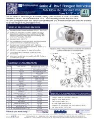
NAMUR PILOT VALVEAutomation & <strong>Controls</strong> Product Group of <strong>SVF</strong> <strong>Flow</strong> <strong>Controls</strong>, <strong>Inc</strong>.The VECTOR-PV4 Series NEMA 4 pilot valves are UL/CSA approved, direct mount (NAMUR VDI/VDE 3845)valves used to pilot pneumatic actuators. The valve is a universal type (5/2 convertible to 3/2) and can beused on double acting or spring return actuators.DESIGN FEATURESqMay be used as a 3-way or 4-way pilot valvefor spring return and double acting actuatorsrespectively.qAvailable in different voltages (120 VAC, 220VAC, 12VDC, 24 VDC).q NAMUR mounting interfaceq Rated to NEMA 4/4X, IP65.q Class “F” coil standard.qEasily field retrofitted for Spring Return andDouble Acting applications.GENERAL SPECIFICATIONSThe VECTOR-PV4 pilot valve is aNEMA 4/4X IP65 version.(Refer to How to Order, below)The VECTOR-PV4 Wiring Diagram can be found on the following pageType 5/2, 3/2Air PressureTemperature40 psi to 120 psi-13 O F to 176 O FVoltages Standard Optional60/50 Hz AC 110V/120V, 220V 24VDC 24V 12VPower ConsumptionAir ConnectionsAC = 4 VA; DC = 4W1/4” NPTAir <strong>Flow</strong> (Cv) 1.1Electrical EntryRating/EnclosureWeight1/2” NPT/DIN TypeNEMA 4 (IP65)1 lb.HOW TO ORDER GUIDESERIESVECTOR-PV4 = NAMUR Mount 3/2 NC and 5/2 Fuctions For SingleActing and Double Acting <strong>Pneumatic</strong> <strong>Actuator</strong>sCE , IP65, NEMA 4,4X ApprovedVOLTAGE110 VAC -4VA 50HZ (Standard)24 VDC -4W (Standard)220 VAC -4VA 50HZ (Optional)12 VDC -4W (Optional)Order Example: (VECTORPV4110VAC)Example Description: VECTOR-PV4, NAMUR Mount Pilot Valve, NEMA 4,4X approved, with 110 VAC Coil.All documents posted on our website supersede all prior publications • [Document #<strong>SVF</strong>_VECTOR-PV4_Data_Sheet • 10/15/2014]© <strong>SVF</strong> <strong>Flow</strong> <strong>Controls</strong>, <strong>Inc</strong>. • 13560 Larwin Circle • Santa Fe Springs, CA 90670 • Tel: 1.800.783.7836 • FAX: 562.802.3114Sales@Nextek<strong>Controls</strong>.net • Visit www.Nextek<strong>Controls</strong>.net for the latest updates on this document • Specifications subject to change.
NAMUR PILOT VALVEAutomation & <strong>Controls</strong> Product Group of <strong>SVF</strong> <strong>Flow</strong> <strong>Controls</strong>, <strong>Inc</strong>.PILOT VALVE DIMENSIONSWiring the VECTOR-PV4PositiveNegativeNote: The coil assembly does notneed to be removed from the pilotvalve for wiring.Dimensions in inches (mm)Bottom ViewGround1. Remove the Housing/Terminal assembly from thecoils by loosening the fastener. Note: Items A and B are asingle unit.2. Remove the Terminal (B) from the housing. (A flat headscrewdriver will help in this)3. Connect the supply wiring as shown above left.4. Insert Terminal block (B) back into the housing5. Slide onto coil and tighten.PILOT VALVE MOUNTING INSTRUCTIONSThe mounting kit includes 2 interface plates that will direct the supply air to the correct manifold ports for either doubleacting (5/2) or Spring return (3/2) actuators. Each interface plate has a set of alignment pins to ensure proper engagement.AlignmentpinsFor Spring Returnactuators useInterface Plate 3/2AlignmentpinsFor Double Actingactuators useInterface Plate 5/2Always note the orientation of the Pilot Valve body, manual override lever and supply air porting when following these instructions.SPRING RETURN ACTUATORS*:Using the 3/2 Interface Plate,mount the Pilot Valve to theactuator as shown.DOUBLE ACTING ACTUATORS:Using the 5/2 Interface Plate, mount the PilotValve to the actuator as shown for:ENERGIZE TO CLOSE**ENERGIZE TO OPEN*Figure A-1 Manual OverrideThe letter “A” Indicatesposition of yellowlever for AutomaticOperation.AutomaticManualFor Manual Override,rotate the yellowlever Clockwise tocorrespond with thearrow as indicated bythe letter “M”.* Supply air porting is on the bottom of the VECTOR ** Supply air porting is on the top of the VECTORMANUAL OVERRIDE: Use of the manual override will by-pass automatic operation. This function is helpful in the event that the valvemust be cycled when electrical supply is unavailable. When the yellow lever is in line with “A” it is in Automatic Operation. ForManual Override, rotate the yellow lever Clockwise as indicated by the letter “M”. Refer to Figure A-1 above.NOTE: For detailed instructions on the VECTOR-PV Series, please refer to the IOM.All documents posted on our website supersede all prior publications • [Document #<strong>SVF</strong>_VECTOR-PV4_Data_Sheet • 10/15/2014]© <strong>SVF</strong> <strong>Flow</strong> <strong>Controls</strong>, <strong>Inc</strong>. • 13560 Larwin Circle • Santa Fe Springs, CA 90670 • Tel: 1.800.783.7836 • FAX: 562.802.3114Sales@Nextek<strong>Controls</strong>.net • Visit www.Nextek<strong>Controls</strong>.net for the latest updates on this document • Specifications subject to change.
ATEX NAMUR PILOT VALVEAutomation & <strong>Controls</strong> Product Group of <strong>SVF</strong> <strong>Flow</strong> <strong>Controls</strong>, <strong>Inc</strong>.The VECTOR-PV7 Series Valve with encapsulated and ATEX approved coils makes this valve excellent forhazardous locations (Flameproof, Ex mb II T4 or T5 and NEC Class I,II Division I Groups A,B,C,D,E,F,G).Each pilot valve is equipped with 3/2 and 5/2 function NAMUR interface plates which allows to be used forboth spring return and double acting actuators.DESIGN FEATURESqqMay be used as a 3-way or 4-way pilot valvefor spring return and double acting actuatorsrespectively.Available in different voltages (120 VAC, 220VAC, 24 VDC).q NAMUR mounting interfaceq ATEX approved for Hazardous Areas.q Class “H” coil standard.qEasily field retrofitted for Spring Return andDouble Acting applications.GENERAL SPECIFICATIONSThe VECTOR-PV7 pilot valve isATEX approved for Hazardous Area Locations.(Refer to How to Order, below)The VECTOR-PV7 Wiring Diagram can be found on the following pageType 5/2, 3/2Air Pressure40 psi to 120 psiTemperature-13 O F to 149 O FVoltages Standard Optional60/50 Hz AC 110V/120V, 220V 24VDC 24VPower ConsumptionAC = 4 VA; DC = 3WAir Connections1/4” NPTAir <strong>Flow</strong> (Cv) 1.1Electrical Entry1/2” NPT/DIN TypeRating/EnclosureIP66, ATEX approved for Hazardous Area LocationsWeight1 lb.HOW TO ORDER GUIDESERIESVECTOR-PV7 = NAMUR Mount 3/2 NC and 5/2 Fuctions For SingleActing and Double Acting <strong>Pneumatic</strong> <strong>Actuator</strong>sCE, ATEX approved for Hazardous Area LocationsOrder Example: (VECTORPV7110VAC)VOLTAGE110 VAC -4VA 50HZ (Standard)24 VDC -4W (Standard)220 VAC -4VA 50HZ (Optional)Example Description: VECTOR-PV7, NAMUR Mount Pilot Valve, with 110 VAC Coil.All documents posted on our website supersede all prior publications • [Document #<strong>SVF</strong>_VECTOR-PV7_Data_Sheet • 10/15/2014]© <strong>SVF</strong> <strong>Flow</strong> <strong>Controls</strong>, <strong>Inc</strong>. • 13560 Larwin Circle • Santa Fe Springs, CA 90670 • Tel: 1.800.783.7836 • FAX: 562.802.3114Sales@Nextek<strong>Controls</strong>.net • Visit www.Nextek<strong>Controls</strong>.net for the latest updates on this document • Specifications subject to change.
ATEX NAMUR PILOT VALVEAutomation & <strong>Controls</strong> Product Group of <strong>SVF</strong> <strong>Flow</strong> <strong>Controls</strong>, <strong>Inc</strong>.PILOT VALVE DIMENSIONSWIRING THE VECTOR PV7The VECTOR-PV7 is pre-wired with a 39” (100mm) lead.39” LeadLt. Blue: PositiveBrown: NegativeDimensions in inches (mm)Bottom ViewGreen/Yellow: GroundPILOT VALVE MOUNTING INSTRUCTIONSThe mounting kit includes 2 interface plates that will direct the supply air to the correct manifold ports for either doubleacting (5/2) or Spring return (3/2) actuators. Each interface plate has a set of alignment pins to ensure proper engagement.AlignmentpinsFor Spring Returnactuators useInterface Plate 3/2AlignmentpinsFor Double Actingactuators useInterface Plate 5/2Always note the orientation of the Pilot Valve body, manual override lever and supply air porting when following these instructions.SPRING RETURN ACTUATORS*:Using the 3/2 Interface Plate,mount the Pilot Valve to theactuator as shown.DOUBLE ACTING ACTUATORS:Using the 5/2 Interface Plate, mount the PilotValve to the actuator as shown for:ENERGIZE TO CLOSE**ENERGIZE TO OPEN*Figure A-1 Manual OverrideThe letter “A” Indicatesposition of yellowlever for AutomaticOperation.AutomaticManualFor Manual Override,rotate the yellowlever Clockwise tocorrespond with thearrow as indicated bythe letter “M”.* Supply air porting is on the bottom of the VECTOR ** Supply air porting is on the top of the VECTORMANUAL OVERRIDE: Use of the manual override will by-pass automatic operation. This function is helpful in the event that the valvemust be cycled when electrical supply is unavailable. When the yellow lever is in line with “A” it is in Automatic Operation. ForManual Override, rotate the yellow lever Clockwise as indicated by the letter “M”. Refer to Figure A-1 above.NOTE: For detailed instructions on the VECTOR-PV Series, please refer to the IOM available on www.<strong>SVF</strong>.net.All documents posted on our website supersede all prior publications • [Document #<strong>SVF</strong>_VECTOR-PV7_Data_Sheet • 10/15/2014]© <strong>SVF</strong> <strong>Flow</strong> <strong>Controls</strong>, <strong>Inc</strong>. • 13560 Larwin Circle • Santa Fe Springs, CA 90670 • Tel: 1.800.783.7836 • FAX: 562.802.3114Sales@Nextek<strong>Controls</strong>.net • Visit www.Nextek<strong>Controls</strong>.net for the latest updates on this document • Specifications subject to change.
Automation & <strong>Controls</strong> Product Group of <strong>SVF</strong> <strong>Flow</strong> <strong>Controls</strong>, <strong>Inc</strong>.DMODeclutchable Manual OverrideThe <strong>SVF</strong> Series “DMO” allows simple and reliable manual positioning of valves, dampers, and otherquarter turn devices to override existing pneumatic or hydraulic rotary actuators. Recommended for all springreturn actuators and on valves with an operating torque in excess of 620 in-lbs, the “DMO” Series is easilyfield installed on existing automated valves and can be adapted to any pneumatic quarter turn actuator.DMOqDESIGN FEATURESCompact, Modular Design - fits between valve andactuator for a complete manual override systemq ISO 5211 Industry Standard Mounting Padq Three Stage Coupler (<strong>Actuator</strong>, Gear, Valve)q Weather-proof to IP-65q Rugged Declutch Lever and Engagement Handleq Six Models available in a wide Torque Rangeq Adjustable travel stops in both directions (Open/Close)qqIntegral Drive Sleeve and Gear - permits smooth,reliable operation for extremely long lifeOptional Vent Valve to exhaust supply air from theactuatorMATERIALS OF CONSTRUCTIONITEM # DESCRIPTION MATERIALS271 BODY (MODELS 38 & 54) DIE CAST ALUMINUM, EPOXY COATED1 BODY (MODEL 80) CAST IRON, EPOXY COATED2 BRACKET CAP (MODELS 38 & 54) DIE CAST ALUMINUM, EPOXY COATED2 BRACKET CAP (MODEL 80) CAST IRON, EPOXY COATED6453 WORM SHAFT CARBON STEEL, POLYESTER COATED4 WORM CARBON STEEL5 BUSHING CARBON STEEL, POLYESTER COATED6 WORM GEAR CAST IRON (QT-500-7GB1348-88)7 LOCK HANDLE SCREW STAINLESS STEEL (SS304)1988 HANDWHEEL CARBON STEEL9 CLUTCH LEVER (HANDLE) CARBON STEEL, POLYESTER COATED10 SHAFT COUPLER STAINLESS STEEL (SS304)103All documents posted on our website supersede all prior publications • [Document #<strong>SVF</strong>_NEXTEK_DMO_Data_Sheet • 05/05/2014]© <strong>SVF</strong> <strong>Flow</strong> <strong>Controls</strong>, <strong>Inc</strong>. • 13560 Larwin Circle • Santa Fe Springs, CA 90670 • Tel: 1.800.783.7836 • FAX: 562.802.3114Sales@Nextek<strong>Controls</strong>.net • Visit www.Nextek<strong>Controls</strong>.net for the latest updates on this document • Specifications subject to change.1
Automation & <strong>Controls</strong> Product Group of <strong>SVF</strong> <strong>Flow</strong> <strong>Controls</strong>, <strong>Inc</strong>.DMODIMENSIONS & SPECIFICATIONS - MODELS D-38-1, D-38-2DMODeclutchable Manual Override“DMO”MODELC D E F G H I J K Lin. mm in. mm in. mm in. mm in. mm in. mm in. mm in. mm in. mm in. mmD-38-1 0.91 23 4.61 117 5.51 140 1.02 26 8.77 223 5.51 140 6.89 175 7.68 195 7.68 195 7.87 200D-38-2 1.10 28 4.61 117 5.71 145 1.02 26 8.77 223 5.51 140 6.89 175 7.68 195 7.68 195 7.87 200“DMO”MODELD1 (Bottom) D2 (Bottom) D3 (Top) D4 (Top) T1 T2 T3 (Through) T4 (Through)in. mm ISO in. mm ISO in. mm ISO in. mm ISO Thread Thread in. mm in. mmD-38-1 2.76 70 F07 4.02 102 F10 - - - 4.02 102 F10 M8 M10 - - 0.55 14D-38-2 2.76 70 F07 4.02 102 F10 - - - 4.02 102 F10 M8 M10 - - 0.55 14“DMO”MODELA (Shaft Bottom) B (Shaft Bottom) M (Shaft Top) N (Shaft Top) Gear Input Torque Output Torquein. mm in. mm in. mm in. mm Ratio in-lbs Nm in-lbs NmD-38-1 0.87 22 0.87 22 0.87 22 0.87 22 38:1 531 60 4868 550D-38-2 0.87 22 0.87 22 1.06 27 1.06 27 38:1 531 60 4868 550See Page 5 for larger drawingBOTTOMTOPDMOHOW TO ORDER GUIDE - MODELS D-38-1, D-38-2MODELCODEGear Input Torque Output Torque ISO 5211 Handwheel WeightRatio in-lbs Nm in-lbs Nm Mounting in. mm lbs kgDMO-38-1 38:1 531 60 4868 550 F07/F10 7.87 200 12 5.5DMO-38-2 38:1 531 60 4868 550 F07/F10 7.87 200 12 5.5Order Example: DMO-38-1 (See following pages for Models D-54 and D-80)Description: Declutchable Manual Override size 38-1 , ISO F07/F10 mounting, 22mm Top & Bottom coupler shaft, 200mm HandwheelAll documents posted on our website supersede all prior publications • [Document #<strong>SVF</strong>_NEXTEK_DMO_Data_Sheet • 05/05/2014]© <strong>SVF</strong> <strong>Flow</strong> <strong>Controls</strong>, <strong>Inc</strong>. • 13560 Larwin Circle • Santa Fe Springs, CA 90670 • Tel: 1.800.783.7836 • FAX: 562.802.3114Sales@Nextek<strong>Controls</strong>.net • Visit www.Nextek<strong>Controls</strong>.net for the latest updates on this document • Specifications subject to change.2
Automation & <strong>Controls</strong> Product Group of <strong>SVF</strong> <strong>Flow</strong> <strong>Controls</strong>, <strong>Inc</strong>.DMODIMENSIONS & SPECIFICATIONS - MODELS D-54-1, D-54-2DMODeclutchable Manual Override“DMO”MODELC D E F G H I J K Lin. mm in. mm in. mm in. mm in. mm in. mm in. mm in. mm in. mm in. mmD-54-1 1.14 29 4.65 118 5.79 147 1.22 31 10.53 268 7.09 180 8.46 215 9.25 235 8.07 205 11.81 300D-54-2 1.46 37 4.65 118 6.02 153 1.22 31 10.53 268 7.09 180 8.46 215 9.25 235 8.07 205 11.81 300“DMO”MODELD1 (Bottom) D2 (Bottom) D3 (Top) D4 (Top) T1 T2 T3 (Through) T4 (Through)in. mm ISO in. mm ISO in. mm ISO in. mm ISO Thread Thread in. mm in. mmD-54-1 4.92 125 F12 - - - 4.92 125 F12 - - - M12 - 0.55 14 - -D-54-2 - - - 5.51 140 F14 - - - 5.51 140 F14 - M16 - - 0.71 18“DMO”MODELA (Shaft Bottom) B (Shaft Bottom) M (Shaft Top) N (Shaft Top) Gear Input Torque Output Torquein. mm in. mm in. mm in. mm Ratio in-lbs Nm in-lbs NmD-54-1 1.06 27 1.06 27 1.06 27 1.06 27 54:1 1062 120 10621 1200D-54-2 1.06 27 1.06 27 1.42 36 1.42 36 54:1 1062 120 10621 1200See Page 5 for larger drawingBOTTOMTOPDMOHOW TO ORDER GUIDE - MODELS D-54-1, D-54-2MODELCODEGear Input Torque Output Torque ISO 5211 Handwheel WeightRatio in-lbs Nm in-lbs Nm Mounting in. mm lbs kgDMO-54-1 54:1 1062 120 10621 1200 F12 11.81 300 20 9DMO-54-2 54:1 1062 120 10621 1200 F14 11.81 300 20 9Order Example: DMO-54-1 (See previous page for Model D-38 and following page for Model D-80)Description: Declutchable Manual Override size 54-1 , ISO F12 mounting, 27mm Top & Bottom coupler shaft, 300mm HandwheelAll documents posted on our website supersede all prior publications • [Document #<strong>SVF</strong>_NEXTEK_DMO_Data_Sheet • 05/05/2014]© <strong>SVF</strong> <strong>Flow</strong> <strong>Controls</strong>, <strong>Inc</strong>. • 13560 Larwin Circle • Santa Fe Springs, CA 90670 • Tel: 1.800.783.7836 • FAX: 562.802.3114Sales@Nextek<strong>Controls</strong>.net • Visit www.Nextek<strong>Controls</strong>.net for the latest updates on this document • Specifications subject to change.3
Automation & <strong>Controls</strong> Product Group of <strong>SVF</strong> <strong>Flow</strong> <strong>Controls</strong>, <strong>Inc</strong>.DMODIMENSIONS & SPECIFICATIONS - MODELS D-80-1, D-80-2DMODeclutchable Manual Override“DMO”MODELC D E F G H I J K Lin. mm in. mm in. mm in. mm in. mm in. mm in. mm in. mm in. mm in. mmD-80-1 1.46 37 5.83 148 7.28 185 1.57 40 14.21 361 9.84 250 11.73 298 12.60 320 9.65 245 15.75 400D-80-2 1.85 47 5.83 148 7.68 195 1.57 40 14.21 361 9.84 250 11.73 298 12.60 320 9.65 245 15.75 400“DMO”MODELD1 (Bottom) D2 (Bottom) D3 (Top) D4 (Top) T1 T2 T3 (Through) T4 (Through)in. mm ISO in. mm ISO in. mm ISO in. mm ISO Thread Thread in. mm in. mmD-80-1 5.51 140 F14 - - - 5.51 140 F14 - - - M16 - 0.71 18 - -D-80-2 - - - 6.50 165 F16 - - - 6.50 165 F16 - M20 - - 0.87 22“DMO”MODELA (Shaft Bottom) B (Shaft Bottom) M (Shaft Top) N (Shaft Top) Gear Input Torque Output Torquein. mm in. mm in. mm in. mm Ratio in-lbs Nm in-lbs NmD-80-1 1.42 36 1.42 36 1.42 36 1.42 36 80:1 1239 140 17701 2000D-80-2 1.42 36 1.42 36 1.81 46 1.81 46 80:1 1239 140 17701 2000See Page 5 for larger drawingBOTTOMTOPDMOHOW TO ORDER GUIDE - MODELS D-80-1, D-80-2MODELCODEGear Input Torque Output Torque ISO 5211 Handwheel WeightRatio in-lbs Nm in-lbs Nm Mounting in. mm lbs kgDMO-80-1 80:1 1239 140 17701 2000 F14 15.75 400 68 31DMO-80-2 80:1 1239 140 17701 2000 F16 15.75 400 68 31Order Example: DMO-80-1 (See previous pages for Models D-38 and D-54)Description: Declutchable Manual Override size 80-1 , ISO F14 mounting, 36mm Top & Bottom coupler shaft, 400mm HandwheelAll documents posted on our website supersede all prior publications • [Document #<strong>SVF</strong>_NEXTEK_DMO_Data_Sheet • 05/05/2014]© <strong>SVF</strong> <strong>Flow</strong> <strong>Controls</strong>, <strong>Inc</strong>. • 13560 Larwin Circle • Santa Fe Springs, CA 90670 • Tel: 1.800.783.7836 • FAX: 562.802.3114Sales@Nextek<strong>Controls</strong>.net • Visit www.Nextek<strong>Controls</strong>.net for the latest updates on this document • Specifications subject to change.4
Automation & <strong>Controls</strong> Product Group of <strong>SVF</strong> <strong>Flow</strong> <strong>Controls</strong>, <strong>Inc</strong>.DMODIMENSIONAL DRAWINGS FOR ALL MODELSBOTTOM OF DMODMODeclutchable Manual OverrideTOP OF DMOScan the barcode with your SmartPhone app and viewthe latest publication of this documentAll documents posted on our website supersede all prior publications • [Document #<strong>SVF</strong>_NEXTEK_DMO_Data_Sheet • 05/05/2014]© <strong>SVF</strong> <strong>Flow</strong> <strong>Controls</strong>, <strong>Inc</strong>. • 13560 Larwin Circle • Santa Fe Springs, CA 90670 • Tel: 1.800.783.7836 • FAX: 562.802.3114Sales@Nextek<strong>Controls</strong>.net • Visit www.Nextek<strong>Controls</strong>.net for the latest updates on this document • Specifications subject to change.5
NOTES: