NAMUR PILOT VALVE - SVF Flow Controls, Inc.
NAMUR PILOT VALVE - SVF Flow Controls, Inc.
NAMUR PILOT VALVE - SVF Flow Controls, Inc.
- No tags were found...

You also want an ePaper? Increase the reach of your titles
YUMPU automatically turns print PDFs into web optimized ePapers that Google loves.
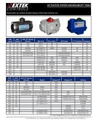
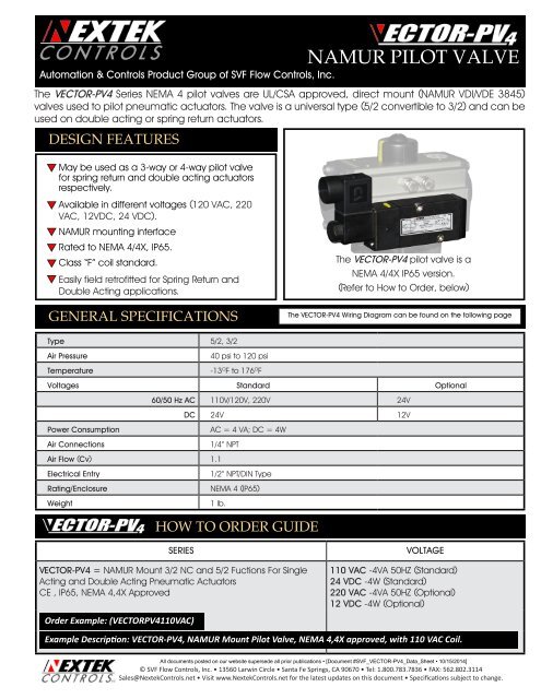
<strong>NAMUR</strong> <strong>PILOT</strong> <strong>VALVE</strong>Automation & <strong>Controls</strong> Product Group of <strong>SVF</strong> <strong>Flow</strong> <strong>Controls</strong>, <strong>Inc</strong>.The VECTOR-PV4 Series NEMA 4 pilot valves are UL/CSA approved, direct mount (<strong>NAMUR</strong> VDI/VDE 3845)valves used to pilot pneumatic actuators. The valve is a universal type (5/2 convertible to 3/2) and can beused on double acting or spring return actuators.DESIGN FEATURESqMay be used as a 3-way or 4-way pilot valvefor spring return and double acting actuatorsrespectively.qAvailable in different voltages (120 VAC, 220VAC, 12VDC, 24 VDC).q <strong>NAMUR</strong> mounting interfaceq Rated to NEMA 4/4X, IP65.q Class “F” coil standard.qEasily field retrofitted for Spring Return andDouble Acting applications.GENERAL SPECIFICATIONSThe VECTOR-PV4 pilot valve is aNEMA 4/4X IP65 version.(Refer to How to Order, below)The VECTOR-PV4 Wiring Diagram can be found on the following pageType 5/2, 3/2Air PressureTemperature40 psi to 120 psi-13 O F to 176 O FVoltages Standard Optional60/50 Hz AC 110V/120V, 220V 24VDC 24V 12VPower ConsumptionAir ConnectionsAC = 4 VA; DC = 4W1/4” NPTAir <strong>Flow</strong> (Cv) 1.1Electrical EntryRating/EnclosureWeight1/2” NPT/DIN TypeNEMA 4 (IP65)1 lb.HOW TO ORDER GUIDESERIESVECTOR-PV4 = <strong>NAMUR</strong> Mount 3/2 NC and 5/2 Fuctions For SingleActing and Double Acting Pneumatic ActuatorsCE , IP65, NEMA 4,4X ApprovedVOLTAGE110 VAC -4VA 50HZ (Standard)24 VDC -4W (Standard)220 VAC -4VA 50HZ (Optional)12 VDC -4W (Optional)Order Example: (VECTORPV4110VAC)Example Description: VECTOR-PV4, <strong>NAMUR</strong> Mount Pilot Valve, NEMA 4,4X approved, with 110 VAC Coil.All documents posted on our website supersede all prior publications • [Document #<strong>SVF</strong>_VECTOR-PV4_Data_Sheet • 10/15/2014]© <strong>SVF</strong> <strong>Flow</strong> <strong>Controls</strong>, <strong>Inc</strong>. • 13560 Larwin Circle • Santa Fe Springs, CA 90670 • Tel: 1.800.783.7836 • FAX: 562.802.3114Sales@Nextek<strong>Controls</strong>.net • Visit www.Nextek<strong>Controls</strong>.net for the latest updates on this document • Specifications subject to change.
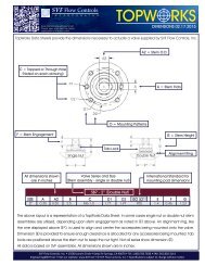
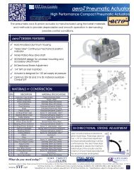
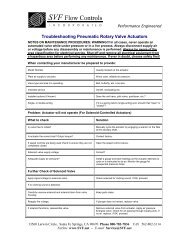
<strong>NAMUR</strong> <strong>PILOT</strong> <strong>VALVE</strong>Automation & <strong>Controls</strong> Product Group of <strong>SVF</strong> <strong>Flow</strong> <strong>Controls</strong>, <strong>Inc</strong>.<strong>PILOT</strong> <strong>VALVE</strong> DIMENSIONSWiring the VECTOR-PV4PositiveNegativeNote: The coil assembly does notneed to be removed from the pilotvalve for wiring.Dimensions in inches (mm)Bottom ViewGround1. Remove the Housing/Terminal assembly from thecoils by loosening the fastener. Note: Items A and B are asingle unit.2. Remove the Terminal (B) from the housing. (A flat headscrewdriver will help in this)3. Connect the supply wiring as shown above left.4. Insert Terminal block (B) back into the housing5. Slide onto coil and tighten.<strong>PILOT</strong> <strong>VALVE</strong> MOUNTING INSTRUCTIONSThe mounting kit includes 2 interface plates that will direct the supply air to the correct manifold ports for either doubleacting (5/2) or Spring return (3/2) actuators. Each interface plate has a set of alignment pins to ensure proper engagement.AlignmentpinsFor Spring Returnactuators useInterface Plate 3/2AlignmentpinsFor Double Actingactuators useInterface Plate 5/2Always note the orientation of the Pilot Valve body, manual override lever and supply air porting when following these instructions.SPRING RETURN ACTUATORS*:Using the 3/2 Interface Plate,mount the Pilot Valve to theactuator as shown.DOUBLE ACTING ACTUATORS:Using the 5/2 Interface Plate, mount the PilotValve to the actuator as shown for:ENERGIZE TO CLOSE**ENERGIZE TO OPEN*Figure A-1 Manual OverrideThe letter “A” Indicatesposition of yellowlever for AutomaticOperation.AutomaticManualFor Manual Override,rotate the yellowlever Clockwise tocorrespond with thearrow as indicated bythe letter “M”.* Supply air porting is on the bottom of the VECTOR ** Supply air porting is on the top of the VECTORMANUAL OVERRIDE: Use of the manual override will by-pass automatic operation. This function is helpful in the event that the valvemust be cycled when electrical supply is unavailable. When the yellow lever is in line with “A” it is in Automatic Operation. ForManual Override, rotate the yellow lever Clockwise as indicated by the letter “M”. Refer to Figure A-1 above.NOTE: For detailed instructions on the VECTOR-PV Series, please refer to the IOM.All documents posted on our website supersede all prior publications • [Document #<strong>SVF</strong>_VECTOR-PV4_Data_Sheet • 10/15/2014]© <strong>SVF</strong> <strong>Flow</strong> <strong>Controls</strong>, <strong>Inc</strong>. • 13560 Larwin Circle • Santa Fe Springs, CA 90670 • Tel: 1.800.783.7836 • FAX: 562.802.3114Sales@Nextek<strong>Controls</strong>.net • Visit www.Nextek<strong>Controls</strong>.net for the latest updates on this document • Specifications subject to change.