

KitchenAid XBP 40TC SX 2V FB - Hob - XBP 40TC SX 2V FB - Hob EN (F030359) Istruzioni per l'Uso
KitchenAid XBP 40TC SX 2V FB - Hob - XBP 40TC SX 2V FB - Hob EN (F030359) Istruzioni per l'Uso
KitchenAid XBP 40TC SX 2V FB - Hob - XBP 40TC SX 2V FB - Hob EN (F030359) Istruzioni per l'Uso

Create successful ePaper yourself
Turn your PDF publications into a flip-book with our unique Google optimized e-Paper software.
Gas supply connection<br />
• Check that the appliance is set for the type of gas available<br />
and then connect it to the mains gas piping or the gas<br />
cylinder in compliance with current regulations and<br />
standards.<br />
• This appliance is designed and set to work with the gas<br />
indicated on the label situated on the actual hob. If the gas<br />
supply is other than the type for which the appliance has<br />
been set, proceed with replacing the corresponding nozzles<br />
(provided), following instructions given in the paragraph<br />
“Adaptation to different types of gas”.<br />
• For trouble-free o<strong>per</strong>ation, suitable use of energy and<br />
longer life of the appliance, make sure that the supply<br />
pressure complies with the values indicated in the table 1<br />
"burners and nozzles specifications, otherwise install a<br />
special pressure regulator on the supply pipe in compliance<br />
with current standards and regulations.<br />
• Connect in such a way that the appliance is subjected to<br />
no strain whatsoever.<br />
Either a rigid metal pipe with fittings in compliance with the<br />
standards in force must be used for connecting to the nipple<br />
union (threaded ½"G male fitting) situated at the rear of the<br />
appliance to the right (fig.5), or flexible steel pipe in<br />
compliance with the standards in force, which must not<br />
exceed 2000 mm in length.<br />
Should it be necessary to turn the fitting, the gasket (supplied<br />
with the appliance) must be replaced.<br />
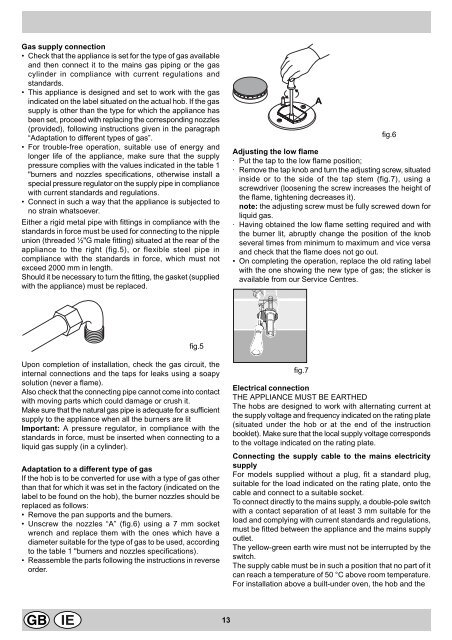
A<br />
fig.6<br />
Adjusting the low flame<br />
· Put the tap to the low flame position;<br />
· Remove the tap knob and turn the adjusting screw, situated<br />
inside or to the side of the tap stem (fig.7), using a<br />
screwdriver (loosening the screw increases the height of<br />
the flame, tightening decreases it).<br />
note: the adjusting screw must be fully screwed down for<br />
liquid gas.<br />
· Having obtained the low flame setting required and with<br />
the burner lit, abruptly change the position of the knob<br />
several times from minimum to maximum and vice versa<br />
and check that the flame does not go out.<br />
• On completing the o<strong>per</strong>ation, replace the old rating label<br />
with the one showing the new type of gas; the sticker is<br />
available from our Service Centres.<br />
fig.5<br />
Upon completion of installation, check the gas circuit, the<br />
internal connections and the taps for leaks using a soapy<br />
solution (never a flame).<br />
Also check that the connecting pipe cannot come into contact<br />
with moving parts which could damage or crush it.<br />
Make sure that the natural gas pipe is adequate for a sufficient<br />
supply to the appliance when all the burners are lit<br />
Important: A pressure regulator, in compliance with the<br />
standards in force, must be inserted when connecting to a<br />
liquid gas supply (in a cylinder).<br />
Adaptation to a different type of gas<br />
If the hob is to be converted for use with a type of gas other<br />
than that for which it was set in the factory (indicated on the<br />
label to be found on the hob), the burner nozzles should be<br />
replaced as follows:<br />
• Remove the pan supports and the burners.<br />
• Unscrew the nozzles “A” (fig.6) using a 7 mm socket<br />
wrench and replace them with the ones which have a<br />
diameter suitable for the type of gas to be used, according<br />
to the table 1 "burners and nozzles specifications).<br />
• Reassemble the parts following the instructions in reverse<br />
order.<br />
fig.7<br />
Electrical connection<br />
THE APPLIANCE MUST BE EARTHED<br />
The hobs are designed to work with alternating current at<br />
the supply voltage and frequency indicated on the rating plate<br />
(situated under the hob or at the end of the instruction<br />
booklet). Make sure that the local supply voltage corresponds<br />
to the voltage indicated on the rating plate.<br />
Connecting the supply cable to the mains electricity<br />
supply<br />
For models supplied without a plug, fit a standard plug,<br />
suitable for the load indicated on the rating plate, onto the<br />
cable and connect to a suitable socket.<br />
To connect directly to the mains supply, a double-pole switch<br />
with a contact separation of at least 3 mm suitable for the<br />
load and complying with current standards and regulations,<br />
must be fitted between the appliance and the mains supply<br />
outlet.<br />
The yellow-green earth wire must not be interrupted by the<br />
switch.<br />
The supply cable must be in such a position that no part of it<br />
can reach a tem<strong>per</strong>ature of 50 °C above room tem<strong>per</strong>ature.<br />
For installation above a built-under oven, the hob and the<br />
13


