

KitchenAid XBP 40TC SX 2V FB - Hob - XBP 40TC SX 2V FB - Hob EN (F030359) Istruzioni per l'Uso
KitchenAid XBP 40TC SX 2V FB - Hob - XBP 40TC SX 2V FB - Hob EN (F030359) Istruzioni per l'Uso
KitchenAid XBP 40TC SX 2V FB - Hob - XBP 40TC SX 2V FB - Hob EN (F030359) Istruzioni per l'Uso

Create successful ePaper yourself
Turn your PDF publications into a flip-book with our unique Google optimized e-Paper software.
oven must be connected separately to the electricity supply<br />
both for safety reasons and for easy removal of the oven if<br />
necessary.<br />
Do not use adapters or shunts as they could cause heating<br />
or burning.<br />
Before connecting to the power supply, make sure that:<br />
• the limiter valve and the domestic system can withstand<br />
the load from the appliance (see rating plate);<br />
• the supply system is efficiently earthed according to<br />
standards and laws in force;<br />
• the socket or double-pole switch are easily accessible when<br />
the appliance is installed.<br />
Important: the wires in the mains lead are coloured in<br />
accordance with the following code:<br />
Green & Yellow - Earth<br />
Blue<br />
- Neutral<br />
Brown<br />
- Live<br />
As the colours of the wires in the mains lead may not<br />
correspond with the coloured markings identifying the<br />
terminals in your plug, proceed as follows:<br />
Connect the Green & Yellow wire to terminal marked “E” or<br />
or coloured Green or Green & Yellow.<br />
Connect the Brown wire to the terminal marked “L” or<br />
coloured Red.<br />
Connect the Blue wire to the terminal marked “N” or coloured<br />
Black.<br />
FAILURE TO OBSERVE THE ACCID<strong>EN</strong>T-PREV<strong>EN</strong>TION<br />
REGULATIONS RELIEVES THE MANUFACTURER OF ALL<br />
LIABILITY.<br />
Replacing the cable<br />
Use a rubber cable of the type H05RR-F with a suitable cross<br />
section 3 x 0.75 mm².<br />
The yellow-green earth wire must be 2-3 cm longer than the<br />
other wires.<br />
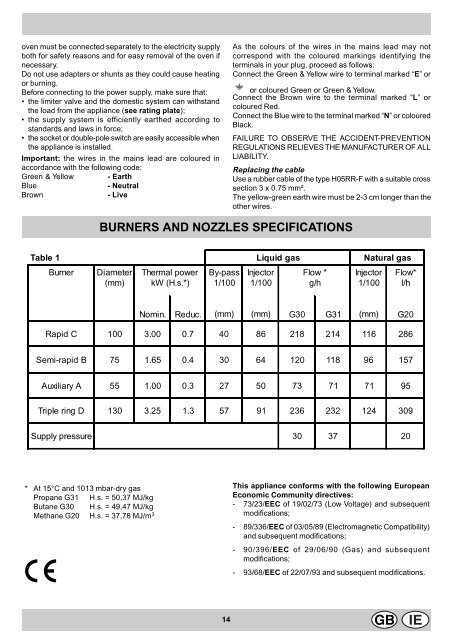
BURNERS AND NOZZLES SPECIFICATIONS<br />
Table 1 Liquid gas Natural gas<br />
Burner Diameter<br />
(mm)<br />
Thermal power<br />
kW (H.s.*)<br />
By-pass<br />
1/100<br />
Injector<br />
1/100<br />
Flow *<br />
g/h<br />
Injector<br />
1/100<br />
Flow*<br />
l/h<br />
Nomin. Reduc. (mm) (mm) G30 G31 (mm) G20<br />
Rapid C 100 3.00 0.7 40 86 218 214 116 286<br />
Semi-rapid B 75 1.65 0.4 30 64 120 118 96 157<br />
Auxiliary A 55 1.00 0.3 27 50 73 71 71 95<br />
Triple ring D 130 3.25 1.3 57 91 236 232 124 309<br />
Supply pressure 30 37 20<br />
* At 15°C and 1013 mbar-dry gas<br />
Propane G31 H.s. = 50,37 MJ/kg<br />
Butane G30 H.s. = 49,47 MJ/kg<br />
Methane G20 H.s. = 37,78 MJ/m 3<br />
This appliance conforms with the following European<br />
Economic Community directives:<br />
- 73/23/EEC of 19/02/73 (Low Voltage) and subsequent<br />
modifications;<br />
- 89/336/EEC of 03/05/89 (Electromagnetic Compatibility)<br />
and subsequent modifications;<br />
- 90/396/EEC of 29/06/90 (Gas) and subsequent<br />
modifications;<br />
- 93/68/EEC of 22/07/93 and subsequent modifications.<br />
14


