Zuggabeln und Zugösen - Jost-Werke GmbH
Zuggabeln und Zugösen - Jost-Werke GmbH
Zuggabeln und Zugösen - Jost-Werke GmbH

You also want an ePaper? Increase the reach of your titles
YUMPU automatically turns print PDFs into web optimized ePapers that Google loves.
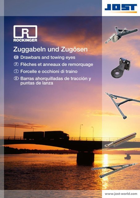
<strong>Zuggabeln</strong> <strong>und</strong> Zugösen<br />
Drawbars and towing eyes<br />
Flèches et anneaux de remorquage<br />
Forcelle e occhioni di traino<br />
Barras ahorquilladas de tracción y<br />
puntas de lanza<br />
www.jost-world.com
D<br />
GB<br />
F<br />
I<br />
E<br />
Für alle aufgeführten Produkte sind<br />
technische Änderungen vorbehalten.<br />
We reserve the right to make changes<br />
to the technical specifications of all the<br />
products depicted in this catalogue.<br />
Tous les produits sont présentés sous<br />
réserve de modifications techniques.<br />
Per tutti i prodotti illustrati ci riserviamo<br />
il diritto di apportare modifiche tecniche.<br />
Respecto a todos los productos indicados<br />
se reservan modificaciones técnicas.<br />
JOST-<strong>Werke</strong><br />
Siemensstraße 2<br />
D-63263 Neu-Isenburg<br />
Tel.: +49 (0) 61 02 / 2 95-0<br />
Fax: +49 (0) 61 02 / 2 95-4 35<br />
E-Mail: jost-sales@jost-world.com<br />
D<br />
GB<br />
F<br />
I<br />
E<br />
www.jost-world.com<br />
<strong>Zuggabeln</strong> von ROCKINGER<br />
2004 hat JOST das traditionsreiche Unternehmen<br />
Regensburger Zuggabel übernommen. Das Unternehmen,<br />
das früher auch unter dem Namen Grau<br />
bekannt war, entwickelt <strong>und</strong> produziert seit fast 80<br />
Jahren <strong>Zuggabeln</strong>. Ab sofort werden diese Produkte<br />
unter der Marke ROCKINGER vertrieben.<br />
ROCKINGER Drawbars<br />
In 2004, JOST took over the long-established<br />
company Regensburger Zuggabel. The company,<br />
formerly known as Grau, has been developing<br />
and producing drawbars for nearly 80 years. From<br />
now on, these products will be sold <strong>und</strong>er the<br />
ROCKINGER brand.<br />
Flèches de remorquage de ROCKINGER<br />
En 2004, JOST a racheté l’entreprise traditionnelle<br />
de flèches de remorquage créée à Ratisbonne.<br />
L‘entreprise, connue auparavant sous le nom de<br />
Grau, développe et produit des flèches de remorquage<br />
depuis près de 80 ans. Dès à présent,<br />
ces produits seront distribués sous la marque<br />
ROCKINGER.<br />
Barre di trazione ROCKINGER<br />
Nel 2004, JOST ha rilevato l’azienda tradizionale<br />
Regensburger Zuggabel. L’azienda, prima nota anche<br />
con il nome Grau, sviluppa e produce barre di trazione<br />
da quasi 80 anni. Fin da subito, questi prodotti<br />
vengono distribuiti sotto il marchio ROCKINGER.<br />
Barras ahorquilladas de ROCKINGER<br />
En 2004 JOST adquirió Regensburger Zuggabel,<br />
una empresa con una larga tradición. La empresa,<br />
también conocida anteriormente por el nombre Grau,<br />
desarrolla y produce barras ahorquilladas desde hace<br />
casi 80 años. A partir de ahora, estos productos serán<br />
distribuidos bajo la marca ROCKINGER.<br />
ROCKINGER<br />
Member of JOST-World<br />
3
Inhaltsverezichnis • Table of contents • Contenu • Indice • Índice<br />
Seite • Page •<br />
Page • Pagina<br />
• Página<br />
Montage- <strong>und</strong> Betriebsanleitung / Hinweise <strong>und</strong> Vorschriften 8<br />
Assembly and Operating Instructions / Directions and Guidelines 11<br />
Indications et réglementations / Notice de montage et d´emploi 14<br />
Istruzioni di montaggio e d´uso / Norme e avvertenze 17<br />
Instrucciones de montaje y de uso / Indicaciones y especificaciones 20<br />
GNZ<br />
GNZ S<br />
GZN<br />
GZA<br />
GZL<br />
GZU<br />
GZV<br />
GZLV<br />
GZHL<br />
GZHU<br />
GZY<br />
GZSY<br />
GSZ<br />
GSG<br />
GH<br />
GHE<br />
GHD<br />
4<br />
ROCKINGER<br />
Member of JOST-World<br />
Seite • Page •<br />
Beschreibung • Description • Description • Descrizione • Descripción<br />
Page • Pagina<br />
• Página<br />
Zuggabel Normalprofil • Drawbar standard profile • Flêche de remorque – profil standard • Timoni<br />
Profilo normale • Perfil normal de la lanza-timón 23<br />
Zuggabel mit schräg eingeschweißter Zugöse • Drawbar with slant welded drawbar eye • Flêche<br />
de remorque avec anneaux de remorquage oudés en biais • Timoni con occhione di traino incli- 24<br />
nato • Lanza-timón con punta de lanza soldada de forma inclinada<br />
Zuggabel mit auswechselbarer Zugöse • Drawbar with interchangeable drawbar eye • Flêche de<br />
remorque avec anneaux deremorquage détachables • Timoni con occhione di traino intercam-<br />
25<br />
biabile • Lanza-timón con punta de lanza cambiable<br />
Zuggabel gekröpft • Drawbar cranked • Flêche de remorque coudée • Timone piegato a gomito •<br />
Lanza-timón acodada 26<br />
Zuggabel längenverstellbar • Drawbar extendable • Flêche de remorque réglable en longueur •<br />
Timone regolabile in lunghezza • Lanza-timón extensible 27<br />
Zuggabel längenverstellbar, leichte Ausführung • Drawbar extendable • Flêche de remorque<br />
réglable en longueur • Timone regolabile in lunghezza • Lanza-timón extensible 28<br />
Zuggabel längenverstellbar • Drawbar extendable • Flêche de remorque réglable en longueur •<br />
Timone regolabile in lunghezza • Lanza-timón extensible 29<br />
Zuggabel längenverstellbar, pneumatisch verriegelbar • Drawbar extendable with pneumatic lock<br />
• Flêche de remorque réglable en longueur avec verrouillage pneumatique • Timone regolabile in 30<br />
lunghezza con blocco pneumatico • Lanza-timón extensible con bloqueo neumático<br />
Zuggabel längenverstellbar mit gekröpfter Zugstange • Drawbar extendable, with cranked towing<br />
bar • Flêche de remorque réglable en longueur, avec barre de traction coudée • Timone regolabile<br />
32<br />
in lunghezza, con barra di trazione piegata a gomito • Lanza-timón extensible, con barra de tracción<br />
acodada<br />
Zuggabel längenverstellbar, gekröpft • Drawbar extendable, cranked • Flêche de remorque<br />
réglable en longueur, coudées • Timone regolabile in lunghezza, piegate a gomito • Lanza-timón 33<br />
extensible, acodada<br />
Zuggabel Y-Form • Drawbar Y shaped • Flêche de remorque, forme en Y • Timoni a Y • Lanzatimón<br />
en forma de Y 34<br />
Zuggabel Y-Form, schräg • Drawbar Y shaped, slant • Flêche de remorque, forme en Y, en biais •<br />
Timoni a Y, inclinato • Lanza-timón en forma de Y, inclinada 35<br />
Zuggabel mit schwenkbarer Zugöse • Pivoting drawbar eye • Anneaux de remorquage interchangeable<br />
• Occhione orientabi • Punta de lanza giratoria 36<br />
Zuggabel mit schwenkbarer Zugöse, gekröpft • Pivoting drawbar eye, cranked • Anneaux de<br />
remorquage interchangeable, coudées • Occhione orientabi, piegate a gomito • Punta de lanza<br />
giratoria, acodada<br />
Höheneinstelleinrichtung, Fixierung durch Klemmung • Height Adjustment System, Fixed using<br />
clamps • Dispositifs d´ajustement de la hauteur réglable, Fixation par serrage • Dispositivi<br />
di regolazione dell´altezza, Fissaggio con bloccaggio • Mecanismo de regulación de la altura,<br />
Fijación mediante un terminal<br />
Höheneinstelleinrichtung, stufenlos auf Zug einstellbar • Height Adjustment System, infinitely<br />
adjustable by pulling • Dispositifs d´ajustement de la hauteur réglable, Réglable en continu sur<br />
traction • Dispositivi di regolazione dell´altezza, Regolazione continua al traino • Mecanismo de<br />
regulación de la altura, ajuste continuo de tracción<br />
Höheneinstelleinrichtung, stufenlos auf Druck einstellbar • Height Adjustment System, infinitely<br />
adjustable by pushing • Dispositifs d´ajustement de la hauteur réglable, Réglable en continu sur<br />
tension • Dispositivi di regolazione dell´altezza, Regolazione continua alla pressione • Mecanismo<br />
de regulación de la altura, ajuste continuo de presión<br />
37<br />
38<br />
38<br />
39
Ersatzteile <strong>und</strong> Zubehör<br />
Spare parts and accessories<br />
Pièces détachées et accessoires<br />
Parti di ricambio e accessori<br />
Piezas de recambio y accesorios<br />
Inhaltsverezichnis • Table of contents • Contenu • Indice • Índice<br />
Seite • Page •<br />
Beschreibung • Description • Description • Descrizione • Descripción<br />
Page • Pagina<br />
• Página<br />
Zugstangenrohre • Towbar pipe • Tubes pour barre de traction • Tubi barre di trazione • Tubos<br />
de barras de tracción 40<br />
Zugstangenrohre • Towbar pipe • Tubes pour barre de traction • Tubi barre di trazione • Tubos<br />
de barras de tracción 40<br />
Seite • Page •<br />
Page • Pagina<br />
• Página<br />
Silentlager • Silent bearings • Palier Silent • Cuscinetto silent • Cojinete silent 41<br />
Lagerbuchsen: (Messing) • Bearing bushes: (brass) • Douilles de palier : (laiton) • Gusci di cusci-<br />
41<br />
netto: (in ottone) • Casquillos de cojinete: (Latón)<br />
Lagerbolzen Form A: (abgesetzt) • Bearing bolt form A: (extended with different diameter) • Axe<br />
de crochet forme A: (étagé) • Perno ganascia forma A: (fissato) • Bulón de articulación forma A:<br />
41<br />
(recortado)<br />
Lagerbolzen Form B • Bearing bolt form B • Axe de crochet, forme B • Perno ganascia forma B<br />
41<br />
• Bulón de articulación forma B<br />
Anschweissaugen • Welding eyes • OEillets de soudure • Occhi saldati • Succión de la soldadura 41<br />
Zugösen 40 mm / 50 mm • Towing eye 40 mm / 50 mm • Anneaux de remorquage 40 mm / 50<br />
42<br />
mm • Occhioni die traino 40 mm / 50 mm • Punta de lanza 40 mm / 50 mm<br />
Übermaßbuchsen • Oversize bushes • Douilles à sur-mesure • Bussole maggiorate • Casquillos<br />
42<br />
de sobremedida<br />
Prüflehren (Kupplungsbolzen <strong>und</strong> Zugösen) • Wear gauge (Coupling pin and towing eye) •<br />
Gabarits (axes d’accouplement et anneaux de remorquage) • Calibri di controllo (perni e occhioni 42<br />
di traino) • Calibres de referencia (perno de acoplamiento y puntas de lanza)<br />
Montagedorn zum Ein- <strong>und</strong> Ausschlagen von Zugösenbuchsen • Mounting tool for hammering<br />
in and removing towing eye bushes • Broche de montage pour enfoncer et ressortir les douilles<br />
42<br />
des anneaux de remorquage • Spina di montaggio per inserire e estrarre le bussole dell’occhione<br />
• Cuña de montaje para introducir y sacar los casquillos de las puntas de lanza<br />
Einroll-Werkzeug für Zugösenbuchsen • Rolling-in device for towing eye bushes • Outil de<br />
roulage pour les douilles des anneaux de remorquage • Avvolgitore per le bussole dell’occhione 42<br />
• Herramienta de introducción de casquillos de puntas de lanza<br />
Aufschlüsselung der Artikel-Nummer • Breakdown to Order No. • Séquençage de la référence • Decodifica del codice<br />
44<br />
articolo • Desglose de los números de artículos<br />
Bestellformular • Order form • Modèle de bon • Modulo per ordine • Formulario de pedido 46<br />
ROCKINGER<br />
Member of JOST-World<br />
5
Verwendete Piktogramme • Used pictographs • Pictogrammes utilisés • Pittogrammi utilizzati • Pictogramas emppleados<br />
D<br />
GB<br />
F<br />
I<br />
E<br />
6<br />
Verwendete Piktogramme<br />
Used pictographs<br />
Picto grammes utilisés<br />
Pittogrammi utilizzati<br />
Pictogramas emppleados<br />
D<br />
C<br />
ROCKINGER<br />
Member of JOST-World<br />
Typ • Type • Type • Tipo • Tipo<br />
U Profil • U profile • Profil U • Profilo a U • Perfil en u<br />
Vierkantprofile • Square profile • Profils quatre pans • Profili a quadro • Perfil cuadrado<br />
Einhängeauge • Securing eye • Œillet d’accrochage • Occhio d’aggancio • Ojo de enganche<br />
n Anzahl der Bohrungen • Number of boreholes • Nombre de forages • Numero di fori • Número de perforaciones<br />
Gewicht • Weight • Poids • Peso • Peso<br />
E Zugöse • Drawbar eye • Remorquage • Occhione • Punta de lanza<br />
V Verschiebeweg • Slide • Course de déplacement • Percorso di spostamento • Espacio desplazable<br />
Av<br />
zulässige Vorderachslast des Drehschemels • Permissible front load of the turning steering frame • Charge avant admise de la selle<br />
orientable • Carico anteriore autorizzato della ralla • Carga delantera permitida del pivote bastidor<br />
empfohlene Gesamtmasse des Anhängers • Recommended maximum weight of the trailer • Masse totale recommandée de la remorque<br />
• Massa totale consigliata del rimorchio • Carga total recomendada del remolque
D<br />
GB<br />
F<br />
I<br />
E<br />
Zugösenübersicht Bezeichnung • Overview of drawbar eyes Description • Vue de l’anneau de remorquage Désignation<br />
• Panoramica degli occhioni di traino Definizione • Vista general de las puntas de lanza Denominación<br />
Zugösenübersicht Bezeichnung<br />
Overview of drawbar eyes Description<br />
Vue de l’anneau de remorquage Désignation<br />
Panoramica degli occhioni di traino Definizione<br />
Vista general de las puntas de lanza<br />
Denominación<br />
E<br />
Zugösenübersicht Bezeichnung • Overview of drawbar eyes Description • Vue de l’anneau de remorquage<br />
Désignation • Panoramica degli occhioni di traino Definizione • Vista general de las puntas de lanza<br />
Denominación a b c<br />
1 40 DIN 74054 A 40 100 30<br />
2 50 DIN 74053 A (EG) 50 115 45<br />
3 50 Schwerlast • Heavy duty • Charge • carico eccez. • carga pesada 50 110 45<br />
4 40 Schweizer Zugöse • Swiss drawbar eye • Anneau de remorquage suisse • Occhione svizzero • Punta de<br />
lanza Suiza<br />
40 115 40<br />
5 57 Skandinavien Zugöse • Skandinavian drawbar eye • Skand. anneau de remorquage • Skand. occhione •<br />
Punta de lanza Skand.<br />
57 184 24<br />
6 76 VG 74059 B 76 158 41<br />
7 76 VG 74059 A* 76 158 41<br />
8 40 DIN 74054 B* 40 100 30<br />
9 40 / 50 Schwenkzugöse • Pivoting drawbar eye • Anneau de remorquage pivotant • Occhione orientabile •<br />
Punta de lanza giratoria<br />
– – –<br />
S 40 CH / 50 Schwenkzugöse • Pivoting drawbar eye • Anneau de remorquage pivotant • Occhione orientabile •<br />
Punta de lanza giratoria<br />
A 40 DIN 11026 Einzelabnahme • Single Item purchase • Achat isolé • Collaudo singolo • Compra única 40 100 42<br />
B 40 DIN – D 140 kN Einzelabnahme • Single Item purchase • Achat isolé • Collaudo singolo • Compra única 40 100 30<br />
C KS✶80 Zugpfanne • Coupling head • Coupelle de traction • Gancio di traino • Cabeza de acoplamiento 80 121 –<br />
S 40 CH – D 168 kN 40 115 40<br />
* = auswechselbar M 45x3 • convertible M 45x3 • remplaçable M 45x3 • intercambiabile M 45x3 • intercambiable M 45x3<br />
a<br />
E<br />
b<br />
c<br />
ROCKINGER<br />
Member of JOST-World<br />
7
Hinweise <strong>und</strong> Vorschriften • Directions and Guidelines • Notice de montage et d´emploi • Norme e avvertenze • Indicaciones y especificaciones<br />
D<br />
Montage- <strong>und</strong> Betriebsanleitung<br />
/ Hinweise<br />
<strong>und</strong> Vorschriften<br />
0. Allgemeines<br />
<strong>Zuggabeln</strong> stellen die Verbindung zwischen Zugmaschine <strong>und</strong><br />
Gelenkdeichselanhänger her. Sie sind zum Anbau an einem<br />
Drehschemel bestimmt.<br />
<strong>Zuggabeln</strong> sind typgenehmigungspflichtige, fahrzeugverbindende<br />
Teile, an die höchste Sicherheitsanforderungen gestellt<br />
werden. Sie dürfen nur in Verbindung mit den bestimmungsgemäßen,<br />
zur Zugöse genehmigten, Anhängerkupplungen<br />
betrieben werden. Veränderungen jeglicher Art (außer die<br />
unter Punkt 2.2 zulässigen) schließen Gewährleistungsansprüche<br />
aus <strong>und</strong> führen zum Erlöschen der Typgenehmigung<br />
<strong>und</strong> damit zum Erlöschen der Fahrzeugbetriebserlaubnis.<br />
<strong>Zuggabeln</strong> werden entsprechend den Richtlinien 94/20 EG<br />
bzw. ECE-R55 der Klasse E gefertigt. Die Montage darf nur<br />
von autorisierten Fachbetrieben <strong>und</strong> nach den geltenden<br />
Richtlinien <strong>und</strong> nationalen Zulassungsvorschriften durchgeführt<br />
werden. Für Deutschland gelten §§ 19,20 <strong>und</strong> 21 der<br />
StVZO sowie die EG-FGV. Weiterhin sind die Auflagen des<br />
§13 FZV hinsichtlich der Mitteilungspflicht bei Änderung von<br />
Fahrzeugdaten zu beachten.<br />
1. Kenndaten <strong>und</strong> Verwendungsbereich<br />
Die zulässigen Belastungsdaten für <strong>Zuggabeln</strong> entnehmen<br />
Sie den Angaben auf dem Fabrikschild oder der Programmübersicht<br />
bzw. den jeweiligen Katalogblättern. Sie gelten für<br />
die bestimmungsgemäße Verwendung entsprechend der<br />
Richtlinie 94/20 EG bzw. ECE-R55.<br />
Bei dynamischen Zusatzbeanspruchungen, z.B. Betrieb auf<br />
unebenen Fahrbahnen, Baustellen <strong>und</strong> Forstwirtschaft,<br />
sollten Sie den D-Wert nicht voll ausnutzen oder eine stärkere<br />
Zuggabel verwenden bzw. bei ROCKINGER nachfragen.<br />
Entscheidend für die Auswahl einer Zuggabel ist der D-Wert<br />
sowie die zul. Vorderachslast des Drehschemels an welchen<br />
sie angebaut werden soll. Die Angaben zur zulässigen<br />
Gesamtmasse des Anhängers dienen als Orientierungshilfe<br />
<strong>und</strong> sind lediglich eine Empfehlung.<br />
Die Eignung der Zuggabel für die Zusammenstellung eines<br />
Zuges kann anhand des angegebenen D-Wertes überprüft<br />
werden.<br />
Zugfahrzeug <strong>und</strong> Gelenkdeichselanhänger: Der D-Wert<br />
• Theoretische Deichselkraft zwischen Zugfahrzeug <strong>und</strong><br />
Anhänger,rechnerischer Vergleichswert von Kräften zwischen<br />
sich bewegenden Massen<br />
8<br />
ROCKINGER<br />
Member of JOST-World<br />
• Der D-Wert läßt sich nur aus dem zulässigen Gesamtgewicht<br />
beider Größen ermitteln (Zugfahrzeug <strong>und</strong> Gelenkdeichselanhänger).<br />
• Berechnung des D-Wertes (kN):<br />
D (kN) =g. T . R<br />
T + R<br />
T : Gesamtgewicht des Zugfahrzeuges in t<br />
R : Gesamtgewicht des Gelenkdeichselanhängers in t<br />
g : Erdbeschleunigung 9,81 m/ s 2<br />
Der errechnete D-Wert darf gleich oder kleiner als der<br />
D-Wert der Zuggabel sein.<br />
Bei der Zusammenstellung des Zuges ist darauf zu achten,<br />
dass der Winkel der Zugöse zur Horizontalen (nach oben oder<br />
unten) nicht mehr als 3° beträgt.<br />
Größere Abweichungen können zu vorzeitigem Verschleiß<br />
oder sogar zur Beschädigung der Zuggabel führen.<br />
2. Montagehinweise<br />
2.1. Montage der Lageraugen<br />
Zur Lagerung von <strong>Zuggabeln</strong> empfehlen wir primär die<br />
Verwendung von Silentbloc-Buchsen.<br />
Silentbloc-Buchsen reduzieren Verschleiß <strong>und</strong> Wartungsaufwand<br />
<strong>und</strong> erhöhen den Komfort.<br />
<strong>Zuggabeln</strong> mit Silentbloc-Buchsen (1):<br />
Zur Befestigung der Zuggabel sind primär Schrauben<br />
(M 30-8.8) zu verwenden. Das Anziehdrehmoment der<br />
selbstsichernden Mutter sollte dabei 400 Nm betragen.<br />
Hierdurch wird die Klemmwirkung des Silentblocs erzielt, die<br />
die Funktion der Radialbewegung über das Gummielement<br />
gewährleistet.<br />
Bei der Erstmontage der Schraube sollte diese mit einem<br />
handelsüblichen Schmierfett oder einer Montagepaste eingesetzt<br />
werden, um eine spätere Demontage zu erleichtern.<br />
Ein Schmieren des Lagers ist nicht nötig.<br />
Um eine Schädigung der Silentbloc-Buchsen zu vermeiden,<br />
sollte der vertikale Schwenkwinkel der <strong>Zuggabeln</strong> ± 20° nicht<br />
überschreiten. Aus diesem Gr<strong>und</strong> wird empfohlen, Silentbloc-<br />
Buchsen nicht für <strong>Zuggabeln</strong> in Verbindung mit Zuggabelabsenkeinrichtungen<br />
zu verwenden.<br />
Schraube<br />
Silentbloc<br />
selbstsichernde<br />
Mutter<br />
Scheibe<br />
Zum Einbau der Silentbloc-Buchsen können auch Federbolzen<br />
verwendet werden.<br />
Die Einbauhinweise sind analog (2) zu beachten.
Hinweise <strong>und</strong> Vorschriften • Directions and Guidelines • Notice de montage et d´emploi • Norme e avvertenze • Indicaciones y especificaciones<br />
<strong>Zuggabeln</strong> mit Messing /Bronze-Verschleißbuchsen (2)<br />
Bolzen Buchse<br />
Bolzen Buchse<br />
Kronenmutter<br />
Scheibe<br />
selbstsichernde<br />
Mutter<br />
Scheibe<br />
Bei der Montage muss darauf geachtet werden, daß die<br />
Zuggabel vertikal beweglich bleibt, in der Lagerung jedoch<br />
spielfrei befestigt ist. Zur Befestigung können Federbolzen<br />
in Verbindung mit „Scheibe / Kronenmutter / Splint“ oder<br />
„Scheibe / selbstsichernde Sechskantmutter“ verwendet<br />
werden. Das Anziehdrehmoment der Kronenmutter sollte<br />
dabei min. 180 Nm betragen. Der Federbolzen sollte vor der<br />
Montage mit einem handelsüblichen Schmierfett oder einer<br />
Montagepaste geschmiert werden. Während des Betriebes<br />
muss der Federbolzen in regelmäßigen Abständen (gemäß<br />
der vorgeschriebenen Wartungsintervalle des Anhängers)<br />
nachgeschmiert werden, oder an die Zentralschmieranlage<br />
angeschlossen sein.<br />
2.2. Montage von Befestigungsteilen /<br />
Reparaturschweißen<br />
Zur Anbringung von Befestigungsteilen zur Aufnahme von<br />
Höheneinstelleinrichtungen, Blindkupplungen <strong>und</strong> dergleichen<br />
sind Bohrungen sowie ein Auge an den Querstreben angebracht.<br />
Des Weiteren können über geeignete Klemmeinrichtungen<br />
(z.B. Federlasche für GHE) zusätzliche Aufnahmepunkte<br />
an den Längsstreben montiert werden.<br />
Sollten die vorgenannten Möglichkeiten nicht ausreichen,<br />
können auf der Längsstrebe Haken oder Augen angeschweißt<br />
werden.<br />
Dabei ist strikt darauf zu achten, dass diese auf der Profilmitte,<br />
mit einer ringsum verlaufenden Kehlnaht (a = 3 mm)<br />
mit großer Sorgfalt anzubringen sind.<br />
Änderungs- oder Reparaturschweißungen sowie Richtarbeiten<br />
an <strong>Zuggabeln</strong> sind strikt untersagt.<br />
2.3. Montage einer Höheneinstelleinrichtung<br />
Die Höheneinstelleinrichtung ist so anzubringen, dass die<br />
angebaute Zuggabel die Anforderungen hinsichtlich Bodenfreiheit<br />
<strong>und</strong> Höheneinstellung der Zugöse erfüllt.<br />
Die Zuggabel muss bodenfrei sein. Die Bodenfreiheit muss<br />
auch beim Herabfallen der Zuggabel aus horizontaler Lage<br />
mindestens 200 mm betragen.<br />
Die Höheneinstelleinrichtung muss so gebaut sein, dass die<br />
Zuggabel von einer Person ohne Zuhilfenahme von Werkzeug<br />
oder anderen Hilfsmitteln auf die Höhe des Fangmauls<br />
der Anhängekupplung am Zugfahrzeug eingestellt werden<br />
kann. Mit der Höheneinstelleinrichtung muss sich die Zugöse<br />
aus horizontaler Lage über der Fahrbahn mindestens 300<br />
mm nach oben <strong>und</strong> nach unten verstellen lassen. In diesem<br />
Bereich muss die Zuggabel stufenlos oder in Stufen von<br />
höchstens 50 mm, gemessen an der Zugöse, verstellbar sein.<br />
Die Höheneinstelleinrichtung darf die leichte Beweglichkeit<br />
der Zuggabel nach dem erfolgten Kupplungsvorgang nicht<br />
beeinträchtigen.<br />
2.4. Hinweis GZU, GZL, GZHL, GZLG, GZV<br />
Längenverstellbare Zugrohre: Die Befestigungs- bzw. Klemmschrauben<br />
sind gemäß den Angaben des zugehörigen Katalogblattes<br />
anzuziehen. Das Zugrohr darf nicht gefettet werden.<br />
2.5 Hinweis GZN 12 <strong>und</strong> 26<br />
GZN 12 u. 26: Das Anzugsmoment der Kronenmutter (SW70)<br />
beträgt min. 500 Nm.<br />
Achtung: Ist die Einführung des Splintes nicht möglich,<br />
unbedingt bis zur nächsten Splintloch-Überdeckung weiter<br />
anziehen. Keinesfalls die Kronenmutter zurückdrehen!<br />
2.6. Hinweis GZLV (pneumatisch verriegelbar)<br />
Druckluftbetätigungsventile zur Ver- bzw. Entriegelung<br />
gehören nicht zum Lieferumfang.<br />
Der Federspeicherzylinder kann einfachwirkend mit Sinterfilter<br />
oder doppelwirkend angeschlossen werden. Die separate<br />
Bedienungsanleitung GZLV ist zu beachten.<br />
2.7. Hinweis: GSG <strong>und</strong> GSZ (Schwenkzugösen)<br />
Bedienung: Federstecker lösen, Knebel von Hand aufschrauben,<br />
Absteckbolzen entfernen, Zugöse 180° schwenken <strong>und</strong> in<br />
um gekehrter Reihenfolge wieder befestigen <strong>und</strong> sichern.<br />
3. Prüf- <strong>und</strong> Instandsetzungshinweise<br />
<strong>Zuggabeln</strong> unterliegen aufgr<strong>und</strong> der auftretenden betriebsüblichen<br />
Beanspruchung normalem Verschleiß. Sie sind daher<br />
in regelmäßigen Abständen nach folgenden Gesichtspunkten<br />
zu prüfen <strong>und</strong> ggf. instandzusetzen.<br />
3.1. Befestigungs- <strong>und</strong> Sicherungselemente<br />
Befestigungs- <strong>und</strong> Sicherungselemente dürfen weder lose<br />
noch beschädigt sein. Lose Befestigungselemente sind mit<br />
den vorgeschriebenen Anziehdrehmomenten nachzuziehen,<br />
schadhafte Befestigungs- oder Sicherungselemente sind zu<br />
ersetzen.<br />
3.2. Lageraugenspiel<br />
Längsspiel max. 2 mm, Seitenspiel max. 4 mm für Bronze-,<br />
Kunststofflager. Für Silentlager ist kein Spiel zulässig.<br />
Lagermaterialablösungen sind nicht zulässig.<br />
(VdTÜV-Merkblatt 712)<br />
3.3. Zuggabelstreben, Zugösenschaft, Schweißnähte<br />
Zuggabelstreben (Längs- <strong>und</strong> Querstreben), Zugösenschaft<br />
<strong>und</strong> Schweißnähte dürfen keine mechanischen Beschädigungen<br />
aufweisen oder übermäßig stark korrodiert sein.<br />
ROCKINGER<br />
Member of JOST-World<br />
9
Hinweise <strong>und</strong> Vorschriften • Directions and Guidelines • Notice de montage et d´emploi • Norme e avvertenze • Indicaciones y especificaciones<br />
<strong>Zuggabeln</strong> mit Verformungen, Anrissen oder Brüchen infolge<br />
unsachgemäßen Betriebs sind nicht mehr verkehrssicher. Sie<br />
dürfen weder gerichtet noch durch andere Reparaturarbeiten<br />
instandgesetzt werden <strong>und</strong> müssen durch neue <strong>Zuggabeln</strong><br />
ersetzt werden.<br />
3.4 Zugösen / Wartung / Prüfung<br />
Um eine möglichst lange Standzeit der Zugöse zu erreichen<br />
ist vor der Inbetriebnahme <strong>und</strong> nach längerem Einsatz die<br />
Zugöse mit zähem, möglichst wasserbeständigem Fett (EP3)<br />
zu schmieren.<br />
Zugösen dürfen nicht beschädigt oder verschlissen sein.<br />
Ausgeschlagene oder lose Verschleißbuchsen sind rechtzeitig<br />
auszutauschen. Verdrehte oder verbogene Zugösen dürfen<br />
keinesfalls gerichtet werden ➠ Unfallgefahr.<br />
Verschleißmaße:<br />
10<br />
b<br />
e<br />
1 Maß mit Buchse<br />
2 Maß ohne Buchse<br />
c<br />
DIN/CH b 1<br />
max. (mm)<br />
3.5. Höheneinstelleinrichtung (HE)<br />
HE dürfen weder lose, beschädigt noch korrodiert sein.<br />
Schadhafte oder übermäßig korrodierte Teile der HE sind<br />
auszutauschen.<br />
Die Funktion der HE muss den Anforderungen nach Abschnitt<br />
2.3. genügen.<br />
4. Oberflächenbehandlung<br />
Optimaler Korrosionsschutz bis zu Längen von 2600mm durch<br />
kathodische Elektro-Tauchlackierung mit Zinkphosphatierung<br />
(KTL Zn). Eine nachträgliche Decklackierung ist bei normalen<br />
Ansprüchen nicht nötig.<br />
<strong>Zuggabeln</strong> mit Längen über 2600 mm sind gestrahlt <strong>und</strong> mit<br />
Aynthal-KH gr<strong>und</strong>iert. Hier ist eine k<strong>und</strong>enseitige Endlackierung<br />
für einen dauerhaften Korrosionsschutz nötig.<br />
ROCKINGER<br />
Member of JOST-World<br />
c<br />
min. (mm)<br />
e 2<br />
min. (mm)<br />
74054 41,5 28,0 22,0<br />
74053 52,5 41,5 23,5<br />
Zugöse CH 41,5 36,5 29,5<br />
11026 41,5 38,0 22,0<br />
Skand. 57 mm 59,5 19,0 -<br />
5. Hinweise zur Identifizierung<br />
<strong>Zuggabeln</strong> sind kennzeichnungspflichtige Bauteile.<br />
Die zugehörigen Belastungsdaten können sie den Angaben<br />
auf dem Fabrikschild entnehmen.<br />
1<br />
2<br />
3<br />
1. Typ<br />
2. Artikel-Nr.<br />
3. zulässiger D-Wert in kN<br />
4. EG-Zulassung<br />
5. zulässige Vorderachslast Av in t<br />
6. ECE-R55 Zulassung<br />
6. Anmerkung<br />
4<br />
Sonderausführungen mit Gutachten zur Erteilung einer Einzelgenehmigung<br />
nach §13 FzTV i.V. m. § 22a StVZO erhalten ein<br />
individuelles Prüfzeichen (TP-Nr.). Das zugehörige Gutachten<br />
wird separat versendet <strong>und</strong> ist bei den Fahrzeugpapieren<br />
mitzuführen.<br />
ROCKINGER hat für fast alle Fahrzeugkombinationen<br />
passende EG- bzw. ECE-typgenehmigte <strong>Zuggabeln</strong>. Um den<br />
Anforderungen des Marktes nachzukommen, sind weitere<br />
Typgenehmigungen geplant, bestehende werden erweitert<br />
<strong>und</strong> ergänzt. Deshalb behalten wir uns Änderungen, die dem<br />
technischen Fortschritt dienen, vor.<br />
6<br />
5
GB<br />
Hinweise <strong>und</strong> Vorschriften • Directions and Guidelines • Notice de montage et d´emploi • Norme e avvertenze • Indicaciones y especificaciones<br />
Assembly and Operating<br />
Instructions / Directions<br />
and Guidelines<br />
0. General information<br />
Drawbars are the connection between the tractor and the<br />
steerable drawbar trailer.<br />
They are designed to be mounted on a pivot support.<br />
Drawbars are parts that are subject to type approval and that<br />
connect vehicles, and are therefore subject to the highest<br />
safety requirements.<br />
They may only be operated with the compliant towing hitches<br />
and towing eyes that have been approved.<br />
Changes of any kind (except for the ones allowed <strong>und</strong>er 2.2)<br />
exclude guarantee claims and type approval is forfeited and<br />
thus the vehicle operating licence as well.<br />
Drawbars are produced in accordance with the Directives<br />
94/20 EC and ECE-R55 Class E. The assembly may only be<br />
completed by authorised specialist companies and according<br />
to the applicable Directives and national approval regulations.<br />
For Germany, §§ 19, 20 and 21 of the StVZO (German Road<br />
Traffic Licensing Regulations) apply. In addition, the conditions<br />
of §13 FZV relating to the duty of notification for alteration of<br />
vehicle data are to be adhered to.<br />
1. Characteristics and range of application<br />
The permissible load conditions for drawbars can be seen<br />
on the inscription on the factory name plate or the product<br />
overview table or the respective catalogue pages. They apply<br />
to the intended use in compliance with the Directive 94 / 20<br />
EC or ECE-R55.<br />
In the case of additional dynamic stress, e.g. operation on<br />
uneven road surfaces, construction sites and forestry, the<br />
D value should not be fully exploited or a stronger drawbar<br />
should be used i.e. enquiries should be made at ROCKINGER.<br />
Decisive for the selection of a drawbar is the D value as well<br />
as the permissible front axle load of the turning steering frame<br />
onto which it is to be attached. Specifications for the permissible<br />
maximum weight of the trailer can be used as an orientation<br />
guide and serve only as a recommendation.<br />
The suitability of a drawbar for the combination of vehicles<br />
can be checked using the specified D value.<br />
Truck and steerable drawbar trailer: The D value<br />
• Theoretical drawbar force between truck and trailer, calculated<br />
reference value of forces between the moving masses<br />
• The D value can only be calculated by the permissible total<br />
weight of both measures (truck and steerable drawbar trailer)<br />
• Calculating the D value (kN):<br />
D (kN) =g. T . R<br />
T + R<br />
T : Total weight of the truck in t<br />
R : Total weight of the steerable drawbar trailer in t<br />
g : acceleration due to gravity, 9.81 m/s 2<br />
The calculated D value may be the less than or equal to the<br />
D value of the drawbar.<br />
When combining vehicles, it must be ensured that the angle<br />
(up or down) of the towing eye is not greater than 3° to the<br />
horizontal axis.<br />
Greater deviations may lead to premature wear or even<br />
damage to the drawbar.<br />
2. Assembly instructions<br />
2.1. Assembling pivots<br />
We primarily recommend the use of Silentbloc bushes for the<br />
bearing of drawbars.<br />
Silentbloc bushes reduce wear and maintenance work and<br />
increase comfort.<br />
Drawbars with Silentbloc bushes (1):<br />
Screws (M 30-8.8) should primarily be used to fasten the<br />
drawbar. The torque of the self-locking nut should be<br />
400 Nm for this. This effectuates the clamping action of the<br />
Silentbloc, which ensures the functionality of the radial motion<br />
using the rubber element.<br />
When first assembling the screw, it should be inserted with<br />
standard lubricating grease or assembly paste, to facilitate<br />
disassembly at a later point in time.<br />
The bearing does not need to be lubricated.<br />
In order to avoid damage to the Silentbloc bushes,the vertical<br />
pivoting angle of the drawbar should not exceed ± 20°. Using<br />
Silentbloc bushes for drawbars fitted with a drawbar height<br />
adjustment device is therefore not recommended.<br />
Screw<br />
Silentbloc<br />
Washer<br />
ROCKINGER<br />
Member of JOST-World<br />
self-locking<br />
nut<br />
Spring bolts can also be used to fasten Silentbloc bushes.<br />
The assembly instructions (2) are also to be observed.<br />
11
Hinweise <strong>und</strong> Vorschriften • Directions and Guidelines • Notice de montage et d´emploi • Norme e avvertenze • Indicaciones y especificaciones<br />
Drawbars with brass/bronze wear bushes (2)<br />
12<br />
Bolt Bush<br />
Bolt Bush<br />
ROCKINGER<br />
Member of JOST-World<br />
Washer<br />
Washer<br />
Castlenut<br />
self-locking<br />
nut<br />
During assembly, it must be ensured that the drawbar<br />
remains vertically movable; in the bearing, however, it must<br />
be free from play. For fastening, spring bolts may be used in<br />
combination with washers/castle nuts/split-pins or washers/<br />
self-locking hex-nuts. The torque of the self-locking nut<br />
should be at least 180 Nm. The spring bolt should be lubricated<br />
with standard lubricating grease or assembly paste prior<br />
to assembly. During operation, the spring bolt must be regularly<br />
greased (according to the trailer’s specified maintenance<br />
intervals), or be connected to a centralised lubricating system.<br />
2.2. Assembly of mounting parts / repair welding<br />
There are boreholes and eyeholes on the cross struts for<br />
attaching fastening fixtures for the mounting of height adjustment<br />
systems, dummy couplings and the like.<br />
Furthermore, additional mounting points can be mounted on<br />
the longitudinal struts using suitable clamping fixtures<br />
(e.g. spring shackles for GHE).<br />
If the aforementioned options are not sufficient, hooks or<br />
eyeholes can be welded onto the longitudinal struts.<br />
When doing so, it must be ensured that they are circumferentially<br />
fillet welded (a = 3mm) to the profile centreline.<br />
Modification or repair welding and straightening work on<br />
drawbars is strictly prohibited.<br />
2.3. Assembling a Height Adjustment System<br />
The height adjustment system is to be assembled such that<br />
the mounted drawbar fulfils requirements for gro<strong>und</strong> clearance<br />
and height adjustment of the drawbar eye.<br />
The drawbar must clear the gro<strong>und</strong>. Gro<strong>und</strong> clearance must<br />
be at least 200 mm, even when dropping the drawbar from<br />
the horizontal position.<br />
The height adjustment system must be constructed such that<br />
the drawbar can be adjusted to the height of the towing hitch<br />
funnel on the tractor by one person without the use of tools<br />
or other aids.<br />
The drawbar eye must be free to move horizontally at least<br />
300 mm up and down horizontal to the road surface with the<br />
height adjustment system. In this area, the drawbar must<br />
be infinitely adjustable or in steps no greater than 50 mm,<br />
measured at the drawbar eye. The height adjustment system<br />
may not impair the light manoeuvrability of the drawbar after<br />
successful coupling.<br />
2.4. Note on GZU, GZL, GZHL, GZLG, GZV<br />
Extendable towing pipe: The fixing and clamping screws<br />
are to be tightened in accordance with the information on<br />
the associated catalogue page. The towing pipe may not be<br />
greased.<br />
2.5 Note on GZN 12 and 26<br />
GZN 12 & 26: The tightening torque of the castle nut (SW70)<br />
is min. 500 Nm.<br />
Caution: If the splint cannot be inserted, you must<br />
continue to screw in up to the next splint hole cover.<br />
Never turn the castle nut backwards!<br />
2.6. Note on GZLV (pneumatically lockable)<br />
Pneumatic operation vents for locking/unlocking are not<br />
included.<br />
The spring loaded cylinder can be connected for single-action<br />
with a sinter filter or for double-action. Please note the separate<br />
instruction manual for GZLV.<br />
2.7. Note: GSG and GSZ (pivoting towing eyes)<br />
Operation: Release the spring cotter, unscrew the locking bolt<br />
by hand, remove the pin bolt, swivel the drawbar by 180°, and<br />
refasten and secure in reverse order.<br />
3. Inspection and maintenance notes<br />
Drawbars are subject to normal wear due to stress occurring<br />
during normal operation. Therefore, they must be checked<br />
with respect to the following criteria at regular intervals and,<br />
if necessary, repaired.<br />
3.1. Mounting and securing elements<br />
Mounting and securing elements may not be loose or<br />
damaged.<br />
Loose mounting elements are to be tightened according<br />
to the specified torques, damaged mounting or securing<br />
elements must be replaced.<br />
3.2. Pivot play<br />
Longitudinal play max. 2 mm, latitudinal play max. 4 mm for<br />
bronze or plastic bearings. No play is allowed for Silent bearings.<br />
Separation of bearing material is not permissible.<br />
(Technical Inspection Authority data sheet 712)<br />
3.3. Drawbar struts, drawbar eye shaft, welding seams<br />
Drawbar struts (longitudinal or latitudinal), drawbar eye shafts<br />
and welding seams may not exhibit any mechanical damage<br />
or be overly corroded. Drawbars with deformations, cracks or<br />
breakages as a result of improper use are no longer roadworthy.
They may neither be straightened nor repaired in any<br />
other way but must be replaced by new drawbars.<br />
3.4 Towing eyes / Maintenance / Inspection<br />
In order to achieve a long tool life of the towing eye, one<br />
has to grease the towing eye before initial operation or after<br />
longer operation with viscous, if possible water-proof, grease<br />
(EP3).<br />
Towing eyes may not be damaged or worn. Knocked out or<br />
loose wear bushes must be replaced in time. Distorted or<br />
twisted towing eyes may not be straightened <strong>und</strong>er any<br />
circumstances ➠ Risk of accident.<br />
Wear mass:<br />
b<br />
e<br />
1 Measuring with bush<br />
2 Measuring without bush<br />
c<br />
DIN/CH b 1<br />
Hinweise <strong>und</strong> Vorschriften • Directions and Guidelines • Notice de montage et d´emploi • Norme e avvertenze • Indicaciones y especificaciones<br />
max. (mm)<br />
3.5. Height adjustment system (HAS)<br />
HASs may not be loose, damaged or corroded. Damaged<br />
or overly corroded parts of the HAS must be replaced.<br />
The functionality of the HAS must fulfil the requirements<br />
specified in section 2.3.<br />
4. Surface treatment<br />
c<br />
min. (mm)<br />
Optimum protection against corrosion up to a length of<br />
2600mm thanks to cathodic e-coating with zinc phosphate<br />
(EPD Zn). A subsequent top coat is not necessary in normal<br />
circumstances.<br />
Drawbars longer than 2600mm are blasted and gro<strong>und</strong>ed with<br />
Aynthal-KH. Lasting protection against corrosion is<br />
ensured without the customer needing to add a final coat.<br />
5. Identification instructions<br />
e 2<br />
min. (mm)<br />
74054 41,5 28,0 22,0<br />
74053 52,5 41,5 23,5<br />
Drawbar eye CH 41,5 36,5 29,5<br />
11026 41,5 38,0 22,0<br />
Skand. 57 mm 59,5 19,0 -<br />
Drawbars are components which must be identified.<br />
The permissible load conditions can be seen on the inscription<br />
on the factory name plate.<br />
1<br />
2<br />
3<br />
1. Type<br />
2. Item No.<br />
3. Permissible D value in kN<br />
4. EC Authorisation<br />
5. Permissible front axle load<br />
6. ECE-R55 authorisation<br />
6. Annotation<br />
4<br />
Special models with a certificate for the issuance of individual<br />
authorisation in accordance with §13 FzTV in connection with<br />
§ 22a StVZO are given individual approval (TP No.). The associated<br />
certificate is sent separately and is to be provided with<br />
the vehicle papers.<br />
ROCKINGER has appropriate EC and ECE type approved<br />
drawbars for almost all vehicle combinations. In order to meet<br />
the requirements of the market, further type approvals are<br />
planned, and existing ones are being extended and added to.<br />
For this reason, all drawbars are subject to changes that are<br />
conducive to technical progress.<br />
We would be happy to answer any further questions.<br />
6<br />
ROCKINGER<br />
Member of JOST-World<br />
5<br />
13
Hinweise <strong>und</strong> Vorschriften • Directions and Guidelines • Notice de montage et d´emploi • Norme e avvertenze • Indicaciones y especificaciones<br />
F<br />
Indications et réglementations<br />
/ Notice de<br />
montage et d´emploi<br />
0. Généralités<br />
Les fourches de remorquage établissent la liaison entre<br />
l’engin de remorquage et la remorque articulée à timon.<br />
Elles sont conçues pour un montage sur une sellette.<br />
Les fourches de remorquage sont soumises à une homologation<br />
de type. En tant que pièces de liaison entre les véhicules,<br />
elles sont soumises aux plus hautes exigences de sécurité.<br />
Elles ne peuvent seulement être entraînées par des attelages<br />
de remorque aux normes par le biais d’anneaux de remorquage<br />
homologués.<br />
Les modifications de toute nature (à l’exception de celles<br />
stipulées dans le sous-menu 2.2) sortent du cadre des modalités<br />
de garantie, impliquent l’annulation de l’homologation de<br />
type et impliquent par conséquent l’autorisation d’exploitation<br />
du véhicule.<br />
Les fourches de remorquage sont conçues en conformité<br />
avec les directives 94/20 CE et/ou avec le règlement ECE-R55<br />
de la classe E.<br />
Le montage ne peut être effectué que par des entreprises<br />
spécialisées autorisés et selon les directives en vigueur et<br />
les dispositions d’autorisation nationales. Pour l’Allemagne,<br />
cela concerne les articles 19, 20 et 21 du StVZO (Règlement<br />
allemand relatif à l’admission des véhicules à la circulation<br />
routière) ainsi que le EG-FGV (Règlement de la CE relatif à<br />
l’admission des véhicules. D’autre part, les obligations de l’art.<br />
13 FZV (Règlement allemand relatif à l’autorisation des véhicules)<br />
doivent être en compte quant aux obligations de donner<br />
des renseignements lors de la modification des données du<br />
véhicule.<br />
1. Caractéristiques et domaine d’utilisation<br />
Vous trouverez les données de charge admissibles pour les<br />
fourches de remorquage sur la plaque du constructeur ou bien<br />
sur l’aperçu du programme et/ou dans les pages du catalogue<br />
correspondantes. Celles-ci sont valables pour les utilisations<br />
conformes aux normes correspondant à la directive 94/20 CE<br />
et/ou au règlement ECE-R55.<br />
Lors de contraintes dynamiques complémentaires, par ex.<br />
dans le cas d’exploitation sur des voies accidentées, chantiers<br />
ou exploitations forestières, vous ne devez pas utiliser<br />
complètement la valeur D ou opter pour une fourche de<br />
remorquage plus résistante. Demandez conseil à ROCKINGER<br />
pour ses fourches de remorquage.<br />
La valeur D d’une fourche de remorquage, tout comme la<br />
charge admissible sur l’essieu avant du timon sur lequel elle<br />
doit être montée sont déterminantes pour le choix d’une<br />
fourche de remorquage. Les données sur la masse totale<br />
admissible de la remorque servent de repère et sont seulement<br />
une recommandation.<br />
14<br />
ROCKINGER<br />
Member of JOST-World<br />
L´aptitude de la fourche de remorque à l’assemblage d’un<br />
véhicule peut être vérifiée à l’aide de la valeur D indiquée.<br />
Tracteur et remorque à timon articulé : la valeur D<br />
• Force théorique sur le timon entre le tracteur et la remorque,<br />
valeur comparative calculée des forces entre deux<br />
masses mobiles.<br />
• La valeur D ne peut être déterminée qu’à partir du poids<br />
total admissible des deux valeurs (tracteur et remorque à<br />
timon articulé).<br />
• Calcul de la valeur D (kN) :<br />
D (kN) =g. T . R<br />
T + R<br />
T : Poids total du tracteur en t<br />
R : Poids total de la remorque en t<br />
g : gravité de la pesanteur 9,81 m / s 2<br />
La valeur D déterminée doit être égale ou inférieure à la<br />
valeur D de la flèche de remorquage.<br />
Lors de l’assemblage du véhicule, il est nécessaire de prendre<br />
en considération le fait que l’angle de l’anneau de remorquage<br />
par rapport à l’horizontale (vers le haut ou vers le bas) ne doit<br />
pas dépasser 3°. Des déviations plus importantes peuvent<br />
entraîner l’usure anticipée de la fourche et même aboutir à<br />
une éventuelle rupture.<br />
2. Indications de montage<br />
2.1. Montage des œillets de palier<br />
Pour le scellement de fourches de remorque, nous vous<br />
conseillons premièrement l’utilisation de coussinets Silent-bloc.<br />
Les coussinets Silent-bloc réduisent l’usure, les frais d’entretien<br />
et augmentent le confort.<br />
Fourches de remorque avec coussinets Silent-bloc (1) :<br />
Utilisez premièrement des vis (M 30-8.8) pour fixer la fourche<br />
de remorque. Le couple de serrage de l’écrou ne pouvant<br />
être desserré doit être de 400 Nm. De cette façon, on<br />
obtient le grippage du Silent-bloc qui assure la fonction du<br />
mouvement radial à l’aide d’un élément en caoutchouc.<br />
Vis Silent-bloc<br />
Rondelle<br />
Ècrou<br />
indesserable<br />
Lors du premier montage de la vis, il est nécessaire de fixer<br />
celle-ci en utilisant de la graisse ou une pâte de montage afin<br />
de faciliter le démontage ultérieur.
Hinweise <strong>und</strong> Vorschriften • Directions and Guidelines • Notice de montage et d´emploi • Norme e avvertenze • Indicaciones y especificaciones<br />
Il n’est pas nécessaire de graisser le palier.<br />
Afin d’éviter un endommagement des coussinets Silent-bloc,<br />
l’angle de rotation verticale de la fourche de remorque ne doit<br />
pas dépasser les ± 20°. Pour cette raison, il est recommandé<br />
de ne pas utiliser les coussinets Silentbloc pour les fourches<br />
de remorque avec un appareillage de rabattement de fourche.<br />
Pour le montage des coussinets Silent-Bloc, des boulons<br />
à ressort peuvent aussi être utilisés. Les indications de<br />
montage sont à suivre de la même manière, voir (2).<br />
Fourches de remorque avec coussinets d’usure en laiton /<br />
bronze (2)<br />
Boulon Bague<br />
Boulon Bague<br />
Rondelle<br />
Rondelle<br />
Ècrou<br />
crénelé<br />
Ècrou<br />
indesserable<br />
Lors du montage, veillez à ce que la fourche reste mobile<br />
verticalement et à ce qu’elle soit fixée sans jeu dans son<br />
articulation. Pour la fixation, vous pouvez utiliser des boulons<br />
à ressort en lien avec les combinaisons « rondelle / écrou<br />
crénelé / goupille fendue » ou « rondelle / écrou six-pans<br />
indesserrable ». Le couple de serrage de l’écrou crénelé<br />
devrait s‘élever au minimum à 180 Nm. Le boulon à ressort<br />
doit être lubrifié avant le montage avec de la graisse ou<br />
une pâte de montage usuelle dans le commerce. Durant le<br />
fonctionnement, le boulon à ressort doit être lubrifié périodiquement<br />
(selon les intervalles d’entretien de la remorque<br />
prescrits) ou joint au dispositif central de graissage.<br />
2.2. Montage des pièces de fixation /<br />
soudures de réparation<br />
Des perçages et un œillet sont placés sur les renforcements<br />
transversaux, permettant de positionner les pièces de fixation<br />
pour les dispositifs d’ajustement de la hauteur, des faux<br />
accouplements et autres.<br />
D’autre part, les dispositifs de serrage appropriés (par ex.<br />
menotte de ressort pour GHE) permettent de monter d’autres<br />
embases de fixation sur les renforcements longitudinaux.<br />
Si les possibilités énoncées précédemment ne suffisent pas,<br />
des crochets ou des œillets peuvent être soudés sur le renforcement<br />
longitudinal.<br />
Veillez strictement à les fixer au centre du profil avec une<br />
soudure d’angle sur les alentours (a = 3 mm) avec un grand soin.<br />
Les soudures de réparation ou de modification tout<br />
comme les travaux d’alignement sur les fourches de<br />
remorquage sont strictement interdits.<br />
2.3. Montage d’un dispositif d’ajustement de la hauteur<br />
Vous devez fixer le dispositif d’ajustement de la hauteur<br />
réglable de telle sorte que la fourche de remorque installée<br />
remplisse les exigences sur la garde au sol et le réglage de la<br />
hauteur des anneaux de remorquage.<br />
La fourche de remorque ne doit pas toucher le sol. La garde<br />
au sol doit, même si la fourche chute de sa position horizontale,<br />
être d’au moins 200 mm.<br />
Le dispositif d’ajustement de la hauteur réglable doit être<br />
construit de telle sorte qu’une personne puisse adapter la<br />
hauteur du pavillon du crochet d’adaptation du véhicule tracteur<br />
sans devoir utiliser d’outils ou d’autres moyens techniques.<br />
L’anneau de remorquage doit pouvoir être déplacé d’au moins<br />
300 mm vers le haut ou vers le bas à partir de la position<br />
horizontale à l’aide du dispositif d’ajustement de la hauteur.<br />
Dans cet intervalle, la fourche de remorque doit pouvoir être<br />
réglée en continu ou bien par crans de max. 50 mm à partir de<br />
l’anneau de remorquage. Après l’attelage, le dispositif d’ajustement<br />
de la hauteur réglable ne doit pas entraver la mobilité<br />
de la fourche.<br />
2.4. Indication GZU, GZL, GZHL, GZLG, GZV<br />
Tube de remorque réglable en longueur : Les vis de fixation<br />
et de serrage doivent être choisis en fonction des données<br />
fournies dans les pages correspondantes du catalogue. Le<br />
tube de remorquage ne doit pas être graissé.<br />
2.5. Indication GZN 12 et 26<br />
GZN 12 et 26 : Le couple de démarrage de l’écrou crénelé<br />
(SW70) est d’au moins 500 Nm.<br />
Attention : Si la mise en place de la goupille n’est pas<br />
possible, continuer le serrage jusqu’au prochain recouvrement<br />
du trou de goupille. Ne desserrer en aucun cas<br />
l’écrou crénelé !<br />
2.6. Indication GZLV (verrouillage pneumatique possible)<br />
Les soupapes d’actionnement d’air comprimé pour le<br />
verrouillage et/ou le déverrouillage ne font pas parties de la<br />
livraison.<br />
Le cylindre de frein à accumulateur peut être joint à simple<br />
effet avec un filtre fritté ou à double effet. Le manuel d’utilisation<br />
GZLV livré séparément doit être respecté.<br />
2.7. Indication : GSG et GSZ (anneaux de remorquage<br />
pivotants)<br />
Utilisation : Débloquez les goupilles, desserrez la manette de<br />
serrage à la main, enlevez le boulon de liaison, faites pivoter<br />
l’anneau de remorquage à 180°, le fixer de nouveau dans le<br />
sens inverse et le sécuriser.<br />
3. Indications de contrôle et de remise en<br />
état<br />
Les flêches de remorque subissent pendant leur utilisation<br />
des usures normales. Par conséquent, elles doivent être<br />
contrôlées et remisent en état périodiquement d´après les<br />
points suivants.<br />
ROCKINGER<br />
Member of JOST-World<br />
15
Hinweise <strong>und</strong> Vorschriften • Directions and Guidelines • Notice de montage et d´emploi • Norme e avvertenze • Indicaciones y especificaciones<br />
3.1. Éléments de fixation et de sécurité<br />
Les éléments de fixation et de sécurité ne doivent pas être<br />
lâches ni abîmés. Des éléments de fixation lâches doivent<br />
être resserrés avec le couple de serrage prescrit, les éléments<br />
de fixation ou de sécurité abîmés doivent être remplacés.<br />
3.2. Jeu des fixations de palier<br />
Jeu axial max. 2 mm, jeu transversal max. 4mm pour des<br />
paliers en bronze ou en plastic. Aucun jeu n´est permis pour<br />
les paliers Silent.<br />
Il est interdit de remplacer le matériel des paliers.<br />
(Vd fiche technique 712 du TÜV)<br />
3.3. Jambe de force de la flêche de remorque, manche de<br />
l´anneau de remorquage, cordon de soudure<br />
Les jambes de force (longitudinales ou transversales) de<br />
la flêche de remorque, le manche de l´anneau de remorquage<br />
et le cordon de soudure ne doivent pas présentés<br />
d´endommagements mécaniques ou bien être excessivement<br />
corrodés.<br />
Les flêches de remorque ayant des déformations, des<br />
fissures ou bien des cassures suite à un emploi inapproprié ne<br />
sont plus sûres. Elles ne doivent ni être réparées ni être mises<br />
en état et doivent être remplacées par de nouvelles flêches.<br />
3.4 Anneaux de remorquage / Maintenance / Vérification<br />
Pour assurer aux anneaux de remorquage une durée de vie<br />
aussi haute que possible, les graisser avant la mise en service<br />
et après une longue utilisation avec un lubrifiant épais et résistant<br />
à l’eau, si possible, (EP3). Les anneaux de remorquage ne<br />
doivent pas être endommagés ou usés.<br />
Changer les douilles d’usure lorsque celles-ci sont détériorées<br />
où qu’elles ne tiennent plus. Ne redresser en aucun cas les<br />
anneaux tordus ou faussés ➠ Danger d’accident.<br />
Masse d’usure :<br />
16<br />
b<br />
e<br />
DIN/CH b 1<br />
1 Dimension avec douille<br />
2 Dimension sans douille<br />
c<br />
max. (mm)<br />
3.5. Dispositif d´ajustement de la hauteur réglable (HE)<br />
Les dispositifs HE ne doivent ni être lâches, ni être abîmés ni<br />
corrodés. Les parties abîmées ou excessivement corrodées<br />
des dispositifs doivent être remplacées. La fonction des<br />
dispositifs doit suffire aux exigences du paragraphe 2.3.<br />
ROCKINGER<br />
Member of JOST-World<br />
c<br />
min. (mm)<br />
e 2<br />
min. (mm)<br />
74054 41,5 28,0 22,0<br />
74053 52,5 41,5 23,5<br />
Anneau de remorquage CH 41,5 36,5 29,5<br />
11026 41,5 38,0 22,0<br />
Skand. 57 mm 59,5 19,0 -<br />
4. Traitement de la surface<br />
Protection optimale contre la corrosion pour des longueurs<br />
allant jusqu’à 2600 mm grâce à un revêtement peinture par<br />
cataphorèse avec phosphatation au zinc (KTL Zn). Il n’est<br />
pas nécessaire d’appliquer une couche de finition pour des<br />
exigences normales.<br />
Les flèches de remorque longues de plus de 2600 mm sont<br />
traitées au jet de sable et de l’Aynthal-KH est appliqué sur<br />
celles-ci. Ici, le client doit appliquer une dernière couche pour<br />
une protection durable contre la corrosion.<br />
5. Indications pour l’identification<br />
Les fourches de remorquage sont des pièces de montage<br />
assujetties à une identification précise.<br />
Les données relatives à la charge peuvent être consultées<br />
directement sur la plaque du constructeur.<br />
4<br />
6<br />
1<br />
5<br />
2<br />
1. Type<br />
2. N° d’article<br />
3. Valeur D autorisée en kN<br />
4. Autorisation CE<br />
5. Charge autorisée de l’essieu avant en t<br />
6. Autorisation ECE-R55<br />
6. Remarque<br />
3<br />
Les constructions spéciales ayant reçu une autorisation<br />
unique après expertise selon l’art.13 FzTV (Règlement allemand<br />
relatif aux pièces des véhicules) en lien avec l’art. 22a<br />
StVZO possèdent un numéro de vérification individuel (N° TP).<br />
L’expertise correspondante est envoyée séparément et doit<br />
être conservée avec les papiers du véhicule.<br />
ROCKINGER possède des fourches de remorquage homologuées<br />
pour les types CE et/ou ECE pour presque tous<br />
types de combinaison de véhicules. Afin de satisfaire aux<br />
exigences du marché, d’autres homologations de type sont<br />
planifiées, les homologations existantes seront amplifiées et<br />
complétées. C´est pourquoi nous nous réservons le droit de<br />
changer tout matériel permettant de faire avancer le progrès<br />
technique.<br />
N’hésitez pas à nous contacter si vous avez d’autres questions.
I<br />
Istruzioni di<br />
montaggio e d´uso /<br />
Norme e avvertenze<br />
0. In generale<br />
Hinweise <strong>und</strong> Vorschriften • Directions and Guidelines • Notice de montage et d´emploi • Norme e avvertenze • Indicaciones y especificaciones<br />
Le forcelle rappresentano il collegamento tra la motrice e il<br />
rimorchio e sono destinate al montaggio sulla ralla.<br />
Le forcelle sono organi di aggancio per articolati ai quali si<br />
richiedono massime garanzie di sicurezza e che di conseguenza<br />
sono soggette all’obbligo di omologazione. Esse<br />
possono essere impiegate solo in conformità alla loro destinazione<br />
d’uso e solo insieme ai ganci di traino omologati per i<br />
rispettivi occhioni. Modifiche di qualsiasi genere (tranne quelle<br />
previste dal punto 2.2) escludono ogni garanzia, invalidano<br />
l’omologazione e di conseguenza il collaudo complessivo del<br />
veicolo.<br />
Le forcelle sono costruite in conformità con la direttiva 94/20<br />
CE, o ECE-R55, classe E. Il montaggio può essere eseguito<br />
solo ad opera di ditte specializzate ed autorizzate ed è<br />
necessario attenersi alle Direttive CE in vigore e alle rispettive<br />
normative di omologazione nazionali (in Germania i §§ 19, 20<br />
e 21 del Codice Stradale) e l’ordinanza CE sull’omologazione<br />
degli autoveicoli (EG-FGV). Si devono inoltre rispettare gli oneri<br />
previsti dal §13 dell’ordinanza sull’immatricolazione dei veicoli<br />
(FZV) sull’obbligo di comunicazione in caso di modifica dei dati<br />
del veicolo.<br />
1. Dati e campo di applicazione<br />
I dati relativi al carico ammissibile per le forcelle sono riportati<br />
sulla targhetta di fabbrica oppure nei rispettivi fogli del<br />
catalogo. Tali dati si riferiscono ad un utilizzo conforme alle<br />
prescrizioni della Direttiva 94/20 CE o ECE-R55. In presenza<br />
di maggiori sollecitazioni dinamiche (per esempio l’impiego su<br />
strade accidentate, in cantieri, nell’economia boschiva) non si<br />
dovrebbe sfruttare completamente il valore D. In questi casi è<br />
consigliabile ricorrere a una forcella più resistente o contattare<br />
la ROCKINGER per ulteriori informazioni.<br />
Il criterio decisivo per la scelta di una forcella è il valore D e il<br />
carico sull’asse anteriore della ralla su cui si intende montare<br />
la forcella. I dati relativi alla massa totale ammessa per il rimorchio<br />
sono valori orientativi e valgono solo quale raccomandazione.<br />
L’idoneità delle forcelle per il traino può essere verificata sulla<br />
base del valore D indicato.<br />
Veicolo trainante e rimorchio: il valore D<br />
• Forza teorica al timone tra il veicolo trainante ed il rimorchio,<br />
valore di calcolo comparativo delle forze tra masse in<br />
movimento<br />
• Il valore D può essere calcolato soltanto dalle masse complessive<br />
ammesse di entrambe le parti (veicolo trainante e<br />
rimorchio).<br />
• Calcolo del valore D (kN):<br />
D (kN) =g. T . R<br />
T + R<br />
T : massa complessiva del veicolo trainante in t<br />
R : massa complessiva del rimorchio in t<br />
g : accelerazione di gravità 9,81 m / s 2<br />
Il valore D calcolato può essere uguale o inferiore al valore D<br />
della forcella di traino.<br />
Nella composizione dell’autotreno è necessario far sì che l’angolo<br />
dell’occhione di traino rispetto all’orizzontale (verso l’alto<br />
o il basso) non superi i 3°.<br />
Differenze maggiori possono provocare un’usura straordinaria<br />
oppure causare la rottura della forcella.<br />
2. Avvertenze per il montaggio<br />
2.1. Montaggio dei supporti con boccola<br />
Quali supporti delle forcelle consigliamo soprattutto le boccole<br />
Silentbloc.<br />
Le boccole Silentbloc riducono l’usura e la manutenzione,<br />
aumentando il grado di confort.<br />
Forcelle con boccole Silentbloc (1):<br />
Per il fissaggio dei forcelle vanno impiegate soprattutto viti<br />
(M 30-8.8). La coppia di serraggio del dado autobloccante<br />
deve essere pari a 400 Nm. È così garantita l’azione di<br />
bloccaggio del Silentbloc per il movimento radiale mediante<br />
guarnizioni di gomma.<br />
Quando la vite viene montata per la prima volta, si dovrebbe<br />
impiegare un grasso lubrificante o una pasta di montaggio che<br />
ne consentano il semplice smontaggio in futuro.<br />
Non è necessario lubrificare il cuscinetto.<br />
Onde evitare il danneggiamento delle boccole Silentbloc,<br />
l’angolo di oscillazione verticale dei forcelle non deve superare<br />
i ± 20°. Per questo motivo si consiglia di non utilizzare boccole<br />
Silentbloc per forcelle dotati di dispositivi di discesa.<br />
Vite Silentbloc<br />
Rondella<br />
ROCKINGER<br />
Member of JOST-World<br />
Dado autobloccante<br />
Per il montaggio delle boccole Silentbloc si possono usare<br />
anche perni molla.<br />
Si prega di osservare in questo caso i consigli per il<br />
montaggio.<br />
17
Hinweise <strong>und</strong> Vorschriften • Directions and Guidelines • Notice de montage et d´emploi • Norme e avvertenze • Indicaciones y especificaciones<br />
Forcelle con boccole di usura in ottone / bronzo (2)<br />
18<br />
Perno Bussola<br />
Perno Bussola<br />
ROCKINGER<br />
Member of JOST-World<br />
Rondella<br />
Rondella<br />
Dado a<br />
corona<br />
Dado autobloccante<br />
Durante il montaggio assicurarsi che la forcella sia libera di<br />
muoversi verticalmente, pur essendo bloccata con un supporto<br />
privo di gioco. Per il fissaggio possono essere impiegati perni<br />
molla in collegamento con “rondella / dado a corona / coppiglia”<br />
o “rondella / dado esagonale autobloccante”.<br />
La coppia di serraggio del dado a corona deve essere<br />
pari ad almeno 180 Nm. Prima del montaggio, il perno molla<br />
dovrebbe essere lubrificato con grasso lubrificante o pasta<br />
di montaggio. Durante l’utilizzo, il perno molla deve essere<br />
lubrificato a intervalli regolari (secondo gli intervalli di lubrificazione<br />
prescritti per il rimorchio), ovvero collegato all’impianto<br />
di lubrificazione centralizzato.<br />
2.2. Montaggio di elementi di fissaggio / Saldature di<br />
riparazione<br />
I tiranti trasversali sono dotati di appositi fori e di un occhiello<br />
per il montaggio di elementi di fissaggio per dispositivi di regolazione<br />
dell’altezza, raccordi di chiusura e simili.<br />
È possibile inoltre anche utilizzare con adeguati dispositivi<br />
di blocco (per esempio biscottini per GHE) punti di supporto<br />
supplementari nei tiranti longitudinali.<br />
Nel caso che le possibilità precedentemente menzionate non<br />
siano sufficienti, è possibile saldare ai tiranti longitudinali ganci<br />
o occhielli supplementari.<br />
Assicurarsi che siano fissati al centro del profilo con la<br />
massima precisione con una saldatura d’angolo continua<br />
(a = 3 mm).<br />
È vietato eseguire modifiche o saldature di riparazione e<br />
lavori di regolazione sulle forcelle.<br />
2.3. Montaggio di un dispositivo di regolazione dell‘altezza<br />
Il dispositivo di regolazione dell’altezza va montato in maniera<br />
tale che la forcella così montata soddisfi i requisiti prescritti in<br />
termini di distanza dal suolo e regolazione in altezza dell’occhione<br />
di traino.<br />
La forcella non può toccare il suolo. La distanza dal suolo<br />
deve corrispondere, anche a forcella abbassata dalla posizione<br />
orizzontale, almeno a 200 mm.<br />
Il dispositivo di regolazione dell’altezza deve essere montato<br />
in maniera tale che una persona, senza il ricorso ad attrezzi o<br />
altri mezzi ausiliari, sia in grado di regolare la forcella all’altezza<br />
della campana del gancio di traino sul veicolo trainante.<br />
Il dispositivo di regolazione dell’altezza deve consentire la<br />
regolazione in alto e in basso dell’occhione di traino, dalla<br />
posizione orizzontale sulla carreggiata, per almeno 300 mm. In<br />
quest’ambito la forcella deve essere regolabile senza soluzione<br />
di continuità o anche a scatti di max. 50 mm misurati<br />
rispetto all’occhione di traino. Il dispositivo di regolazione<br />
dell’altezza non può impedire il facile movimento della forcella<br />
ad agganciamento completato.<br />
2.4. Note per forcelle GZU, GZL, GZHL, GZLG, GZV<br />
Tubo di traino a lunghezza regolabile. Le viti di fissaggio o di<br />
bloccaggio devono essere strette in base alle indicazioni della<br />
relativa pagina del catalogo. Il tubo di traino non deve essere<br />
ingrassato.<br />
2.5 Note per forcelle GZN 12 e 26<br />
GZN 12 e 26: Il momento di serraggio del dado a corona<br />
(SW70) deve essere di almeno 500 Nm.<br />
Attenzione: Se non è possibile inserire la coppiglia, continuare<br />
assolutamente a stringere fino alla copertura del<br />
foro della coppiglia successiva. È assolutamente vietato<br />
svitare il dado a corona!<br />
2.6. Nota per forcelle GZLV (a bloccaggio pneumatico)<br />
Le valvole di comando ad aria compressa per il bloccaggio e lo<br />
sbloccaggio non fanno parte dei pezzi in dotazione.<br />
Il cilindro del freno a molla si può collegare semplicemente<br />
con filtro di sinterizzazione o a effetto doppio. Seguire le istruzioni<br />
d’uso separate del modello GZLV.<br />
2.7. Nota: GSG e GSZ (anelli di traino orientabili)<br />
Uso: allentare lo spinotto a scatto, svitare manualmente la<br />
vite ad alette, estrarre il perno ad incastro, ruotare l’occhione<br />
di traino di 180° e ristringere e fissare gli elementi in ordine<br />
inverso.<br />
3. Istruzioni per la verifica e<br />
la manutenzione<br />
In condizioni di normale sollecitazione in fase di utilizzo, i<br />
timoni sono sottoposti a normale usura. Essi vanno quindi<br />
sottoposti a intervalli regolari di controllo e, se necessario, a<br />
manutenzione secondo i seguenti criteri.<br />
3.1. Elementi di fissaggio e di sicurezza<br />
Gli elementi di fissaggio e di sicurezza non devono essere<br />
allentati o danneggiati. Serrare gli elementi di fissaggio alle<br />
coppie di serraggio prescritte e sostituire gli elementi di<br />
fissaggio e di sicurezza eventualmente danneggiati.<br />
3.2. Gioco dei supporti<br />
Gioco longitudinale max. 2 mm, gioco trasversale max. 4 mm<br />
per supporti in bronzo o materiale plastico. Per i supporti in<br />
gomma non è consentito nessun gioco.<br />
Non sono consentiti scollanti per il materiale dei supporti.<br />
(circolare TÜV 712)
3.3. Tiranti, corpi degli occhioni di traino, saldature<br />
I tiranti dei timoni (tiranti longitudinali e trasversali), i corpi<br />
degli occhioni di traino e le saldature non possono presentare<br />
danni meccanici o corrosione eccessiva. I timoni che presentano<br />
distorsioni, strappi o punti di rottura dovuti ad un uso non<br />
appropriato non sono più sicuri e sono quindi da sostituire<br />
con nuovi timoni. È vietato sottoporre i timoni danneggiati a<br />
raddrizzatura o riparazioni di altro tipo.<br />
3.4 Timoni / Manutenzione / Controllo<br />
Per garantire la massima durata di funzionamento dell’occhione<br />
di traino, prima di metterlo in funzione e dopo un<br />
impiego prolungato lubrificarlo con grasso adatto resistente<br />
all’acqua (EP3).<br />
Gli occhioni di traino non devono essere né danneggiati né<br />
usurati.<br />
Sostituire per tempo le bussole di usura ammaccate o allentate.<br />
Evitare assolutamente di raddrizzare occhioni storti o<br />
deformati ➠ Pericolo di incidente!<br />
Limite di usura:<br />
b<br />
e<br />
1 Misura con bussola<br />
2 Misura senza bussola<br />
Hinweise <strong>und</strong> Vorschriften • Directions and Guidelines • Notice de montage et d´emploi • Norme e avvertenze • Indicaciones y especificaciones<br />
DIN/CH b 1<br />
c<br />
max. (mm)<br />
3.5. Dispositivo di regolazione dell´altezza (HE)<br />
I dispositivi di regolazione dell´altezza non possono essere<br />
allentati, danneggiati o corrosi. Tutte le parti danneggiate<br />
o eccessivamente corrose dei dispositivi di regolazione<br />
dell´altezza vanno sostituite. Il funzionamento dei dispositivi<br />
di regolazione dell´altezza deve soddisfare i requisiti di cui al<br />
paragrafo 2.3.<br />
4. Trattamento di superficie<br />
c<br />
min. (mm)<br />
e 2<br />
min. (mm)<br />
74054 41,5 28,0 22,0<br />
74053 52,5 41,5 23,5<br />
Occhione di traino CH 41,5 36,5 29,5<br />
11026 41,5 38,0 22,0<br />
Skand. 57 mm 59,5 19,0 -<br />
Protezione anticorrosione ottimale fino a lunghezze di<br />
2600mm con verniciatura elettrocatodica per immersione con<br />
fosfatazione allo zinco (KTL Zn). In caso di esigenze normali<br />
non è necessaria la verniciatura di copertura supplementare.<br />
Le forcelle di lunghezza superiore a 2600 mm sono sabbiate<br />
e con fondo in Synthal-KH. In questo caso è necessaria una<br />
verniciatura finale da parte del cliente per una protezione anticorrosione<br />
permanente.<br />
5. Avvertenze sull‘identificazione<br />
Le forcelle sono componenti soggetti all’obbligo di contrassegno.<br />
I dati relativi al carico ammissibile sono riportati sulla targhetta<br />
di fabbrica.<br />
4<br />
6<br />
1<br />
5<br />
2<br />
1. Tipo<br />
2. Codice articolo<br />
3. Valore D ammesso in kN<br />
4. Omologazione CE<br />
5. Carico asse anteriore ammesso Av in t<br />
6. Omologazione ECE-R55<br />
6. Annotazione<br />
3<br />
Ai modelli speciali con perizia per il conferimento di un’autorizzazione<br />
singola ai sensi del §13 dell’ordinanza sui componenti<br />
degli autoveicoli (FzTV) associata al § 22a del Codice Stradale<br />
viene assegnato un codice di controllo individuale (codice TP).<br />
La relativa perizia verrà inviata in via separata e dovrà essere<br />
portata con sé insieme agli altri documenti del veicolo.<br />
ROCKINGER dispone di modelli omologati CE o ECE di<br />
forcelle adatte per qualsiasi combinazione con veicoli. Per<br />
soddisfare le esigenze del mercato sono già previste altre<br />
omologazioni, nonché l’ampliamento e l’integrazione di quelle<br />
già disponibili. Pertanto ci riserviamo il diritto di modifiche<br />
dovute al progresso tecnico. Siamo a vostra completa disposizione<br />
per qualsiasi chiarimento.<br />
ROCKINGER<br />
Member of JOST-World<br />
19
Hinweise <strong>und</strong> Vorschriften • Directions and Guidelines • Notice de montage et d´emploi • Norme e avvertenze • Indicaciones y especificaciones<br />
E<br />
Instrucciones de montaje<br />
y de uso / Indicaciones<br />
y especificaciones<br />
0. Información general<br />
Las barras ahorquilladas de tracción representan la conexión<br />
entre la máquina de tracción y el remolque del brazo de tiro<br />
articulado.<br />
Éstas pueden ser montadas en un pivote de giro.<br />
Las barras ahorquilladas de tracción son un tipo de piezas<br />
sujetas a autorización que unen vehículos, por lo que deben<br />
cumplir los más altos requisitos de seguridad. Éstas sólo<br />
pueden ser utilizadas con los acoplamientos de remolques<br />
específicos que a su vez están autorizados para las puntas de<br />
lanza.<br />
Cualquier modificación realizada (excepto modificaciones<br />
aceptadas bajo el punto 2.2) conlleva la exclusión de cualquier<br />
derecho a garantía, con lo cual se extinguirá la licencia para<br />
este tipo y con ello el permiso de uso de dicho automóvil.<br />
Las barras ahorquilladas de tracción de la empresa se construyen<br />
conforme las directrices 94/20 CE y ECE-R55 de<br />
clase E. Su montaje debe ser realizado únicamente por una<br />
empresa técnica autorizada, siguiendo las directrices y las<br />
normas nacionales de admisión vigentes. En Alemania son<br />
vigentes las normas §§ 19,20 y 21 de StVZO (orden alemana<br />
de permiso de circulación de vehículos) y la CE-FGV (reglamento<br />
alemán de homologación de vehículos). Además se<br />
han de tener en cuenta las condiciones descritas en §13 FZV<br />
referentes a la obligación de notificación del cambio de los<br />
datos del vehículo.<br />
1. Características y campo de aplicación<br />
Los datos sobre la carga máxima permitida para las barras<br />
ahorquilladas de tracción se encuentran en la placa del fabricante<br />
o en la vista general del programa y en las hojas del<br />
catálogo. Estos datos son válidos en caso de hacer un uso<br />
adecuado, siguiendo las normas 94 / 20 CE y ECE-R55.<br />
En caso de realizar esfuerzos dinámicos adicionales, como p.<br />
ej. debidos a su utilización en terrenos irregulares, en zonas<br />
de obras o en el campo, no debería alcanzar el valor D máximo<br />
o debería utilizar una barra ahorquillada de tracción más fuerte.<br />
En estos casos le recomendamos que se ponga en contacto<br />
con la empresa ROCKINGER.<br />
Para la elección de una barra ahorquillada de tracción son decisivos<br />
el valor D y la carga permitida en la tracción delantera<br />
de la quinta rueda, en la cual debe ser montada. Los valores<br />
de la carga total permitida del remolque son únicamente una<br />
recomendación y sirven como valores orientativos.<br />
Para saber si una barra ahorquillada de tracción es apropiada<br />
o no para el montaje en una tracción, se puede realizar una<br />
verificación, introduciendo el valor D necesario.<br />
20<br />
ROCKINGER<br />
Member of JOST-World<br />
Veicolo trainante e rimorchio: il valore D<br />
• Fuerza teórica del brazo de tiro entre el vehículo de tracción<br />
y el remolque, valor de referencia calculado para las fuerzas<br />
existentes entre dos masas en movimiento<br />
• El valor D sólo puede ser determinado a partir del peso total<br />
permitido de ambas magnitudes (vehículo de tracción y<br />
remolque del brazo de tiro articulado).<br />
• Cálculo del valor D (kN):<br />
D (kN) =g. T . R<br />
T + R<br />
T : Peso total del vehículo de tracción en t<br />
R : Peso total del remolque con brazo de tiro articulado en t<br />
g : Aceleración de la gravedad 9,81 m / s 2<br />
El valor D calculado puede ser igual o menor al valor D de la<br />
barra ahorquillada de tracción.<br />
Al unir dos vehículos se ha de tener en cuenta que el ángulo<br />
de la punta de lanza respecto a la horizontal (hacia arriba o<br />
hacia abajo) no sea mayor a 3°. Variaciones más grandes<br />
pueden ocasionar un desgaste prematuro o incluso el daño de<br />
la barra ahorquillada de tracción.<br />
2. Indicaciones de montaje<br />
2.1. Montaggio dei supporti con boccola<br />
Para la articulación de las barras ahorquilladas de tracción de<br />
se recomienda la utilización de los casquillos de bloque Silent.<br />
Los casquillos de bloque Silent reducen el desgaste y la necesidad<br />
de mantenimiento, y aumentan el confort.<br />
Barras ahorquilladas de tracción con casquillos de bloque<br />
Silent (1):<br />
Para la fijación de la barra ahorquillada de tracción se han de<br />
utilizar tornillos (M30-8.8). El par de apriete del las tuercas<br />
autofijadoras debe tener un valor de 400 Nm. De esta<br />
manera se consigue la fijación mediante el bloque Silent que<br />
garantiza el movimiento radial sobre el cuerpo de goma.<br />
En su primer montaje, el tornillo debe ser impregnado con<br />
un lubricante corriente o una pasta de fijación para facilitar su<br />
desmontaje en el futuro.<br />
No es necesaria la lubricación del cojinete.<br />
Para evitar un deterioro de los casquillos de bloque Silent, el<br />
ángulo de giro vertical de las barras de tracción no debe sobrepasar<br />
los ±20°. Por éste motivo se recomienda no utilizar<br />
los casquillos del bloque Silent para barras ahorquilladas de<br />
tracción en conexión con sistemas de descenso de las barras<br />
ahorquilladas.
Hinweise <strong>und</strong> Vorschriften • Directions and Guidelines • Notice de montage et d´emploi • Norme e avvertenze • Indicaciones y especificaciones<br />
Tornillo Bloque Silent<br />
Arandela<br />
Tuerca<br />
autofijadora<br />
Per il montaggio delle boccole Silentbloc si possono usare<br />
anche perni molla.<br />
Si prega di osservare in questo caso i consigli per il montaggio.<br />
Para el montaje de los casquillos del bloque Silent también se<br />
pueden emplear bulones.<br />
Las indicaciones de instalación son análogas a (2).<br />
Barras ahorquilladas de tracción con casquillos de<br />
desgaste de latón/bronce (2)<br />
Bulón Casquillo<br />
Bulón Casquillo<br />
Tuerca<br />
almenada<br />
Arandela<br />
Arandela<br />
Tuerca<br />
autofijadora<br />
Durante el montaje se ha de tener en cuenta que la barra<br />
ahorquillada de tracción ha de permanecer móvil en dirección<br />
vertical y la articulación debe estar fijada sin posibilidad de<br />
movimiento. Para la fijación se pueden utilizar bulones en<br />
conexión con “arandela / tuerca almenada / clavija hendida” o<br />
“arandela / tuerca hexagonal autofijadora”. El par de apriete<br />
del las tuercas almenadas debe tener un valor mín. de<br />
180 Nm. Antes de su montaje, el bulón debe ser impregnado<br />
con un lubricante corriente o con una pasta de montaje.<br />
Durante su funcionamiento, el bulón debe volver a ser impregnado<br />
en intervalos uniformes (según los intervalos de revisión<br />
especificados para el remolque), o debe estar conectado al<br />
sistema lubrificante centralizado.<br />
2.2. Montaje de elementos de fijación / soldaduras de<br />
reparación<br />
Para la instalación de elementos de fijación durante la instalación<br />
de mecanismos de regulación de la altura, acoplamientos<br />
falsos y otros mecanismos parecidos es necesario realizar<br />
perforaciones y una abertura en el soporte transversal.<br />
Adicionalmente puede emplear otros mecanismos de fijación<br />
adecuados (p. ej. un grillete de suspensión para GHE).<br />
Si las posibilidades nombradas anteriormente no son suficientes,<br />
también se pueden soldar ganchos o aberturas en los<br />
soportes longitudinales.<br />
Para ello se debe tener rigurosamente en cuenta que estos se<br />
deben fijar mediante un cordón angular (a = 3mm) en el medio<br />
de su perfil.<br />
Está estrictamente prohibida la realización de soldaduras<br />
de cambio o de reparación y el perfeccionamiento en las<br />
barras ahorquilladas de tracción.<br />
2.3. Montaje de un mecanismo de regulación de la altura<br />
El mecanismo de regulación de la altura ha de ser instalado<br />
de tal manera, que la barra de tracción fijada anteriormente<br />
cumpla con las exigencias de distancia al suelo y de regulación<br />
de altura de la punta de lanza.<br />
La barra ahorquillada de tracción debe situarse a cierta distancia<br />
del suelo. Al dejar descender la barra de tracción, su distancia<br />
al suelo, en posición horizontal, debe de ser como mínimo de<br />
200 mm.<br />
El mecanismo de regulación de la altura debe ser instalado de<br />
tal manera, que la barra de tracción pueda ser ajustada por una<br />
persona a la altura de la boca de enganche del remolque en el<br />
vehículo de tracción sin la ayuda de herramientas u otros medios.<br />
Con el mecanismo de regulación de la altura, la punta de lanza<br />
se debe poder ajustar por lo menos 300mm hacia arriba y<br />
hacia abajo en posición horizontal sobre la calzada. En este<br />
intervalo, la barra ahorquillada de tracción debe ser regulable<br />
de forma continua o gradualmente en escalones de 50 mm<br />
como máximo, medidos a partir de la punta de lanza. Después<br />
del proceso de acoplamiento, el mecanismo de regulación de<br />
la altura no puede impedir el fácil desplazamiento de la barra<br />
de tracción.<br />
2.4. Instrucciones GZU, GZL, GZHL, GZLG, GZV<br />
Tubos de tracción extensibles: Los tornillos de fijación y de<br />
apriete deben ser apretados tal y como se indica en las hojas<br />
del catálogo correspondiente. El tubo de tracción no debe ser<br />
lubricado.<br />
2.5 Instrucción GZN 12 y 26<br />
GZN 12 y 26: El par de apriete de la tuerca almenada (SW70)<br />
debe tener un valor mín. de 500 Nm.<br />
Atención: Si no puede introducir la clavija hendida, siga<br />
apretando hasta la próxima cubierta del agujero de la<br />
clavija. ¡No desatornille nunca la tuerca almenada!<br />
2.6. Instrucción GZLV (enclave neumático)<br />
Las válvulas de accionamiento neumático necesarias para el<br />
bloqueo o desbloqueo no están incluidas en el pedido.<br />
El cilindro almacenador de fuerza por muelle puede ser conectado<br />
como cilindro de efecto simple mediante un filtro sinterizado<br />
o como cilindro de doble efecto. Tenga en cuenta las<br />
instrucciones de manejo GZLV suministradas por separado.<br />
2.7. Advertencia: GSG y GSZ (punta de lanza giratoria)<br />
Manejo: Desmontar la clavija elástica de fijación, desenroscar<br />
la manilla manualmente, retirar el bulón de ajustamiento, girar<br />
ROCKINGER<br />
Member of JOST-World<br />
21
Hinweise <strong>und</strong> Vorschriften • Directions and Guidelines • Notice de montage et d´emploi • Norme e avvertenze • Indicaciones y especificaciones<br />
la punta de lanza 180°. Volver a ajustar y a asegurar en orden<br />
inverso.<br />
3. Instrucciones de control y reparación<br />
Las lanzas-timón muestran un nivel de desgaste durante<br />
su utilización. Éstas deben ser controladas en espacios de<br />
tiempo uniformes y si es necesario, también han de ser reparadas.<br />
3.1. Elementos de sujeción y de seguridad<br />
Los elementos de sujeción y de seguridad no pueden estar<br />
sueltos ni dañados. Elementos de sujeción sueltos han de ser<br />
apretados con el par de apriete especificado. Los elementos<br />
de sujeción o de seguridad dañados han de ser reemplazados.<br />
3.2. Hulgura de ojos del soporte<br />
Hulgura axial máx. de 2 mm, juego lateral máx. de 4 mm para<br />
cojinetes de bronce o de plástico. Para los Silentbloc no se<br />
admite ninguna hulgura.<br />
No está permitido reemplazar el material de los cojinetes.<br />
(Hoja de instrucciones 712 de TÜV)<br />
3.3. Soportes de la lanza-timón, grupos de puntas de<br />
lanzas, cordones de soldadura<br />
Los soportes de la lanza-timón (soportes longitudinal y<br />
transversal), los grupos de puntas de lanzas y los cordones<br />
de soldadura no pueden presentar daños mecánicos o estar<br />
excesivamente corroído. Las lanzas-timón que presentan<br />
deformaciones, grietas o roturas que implican un servicio<br />
inadecuado no son seguras para la circulación. Éstas no<br />
pueden ser enderezadas de nuevo ni reparadas y deben ser<br />
reemplazadas por otras nuevas.<br />
3.4 Puntas de lanza / Mantenimiento / Evaluación<br />
Para conseguir una larga duración de uso de las puntas de<br />
lanza, debe lubricarlas con una grasa viscosa y resistente al<br />
agua (EP3) antes de su primera puesta en funcionamiento y<br />
también tras su larga utilización.<br />
Las puntas de lanza no pueden estar dañadas o desgastadas.<br />
Se han de reemplazar a tiempo los casquillos de desgaste<br />
dañados o sueltos. No se deben enderezar las puntas de lanza<br />
torcidas o dobladas ➠ Peligro de accidente.<br />
Masa de desgaste:<br />
e<br />
b<br />
DIN/CH b 1<br />
1 Medida con casquillo<br />
2 Medida sin casquillo<br />
22<br />
c<br />
max. (mm)<br />
ROCKINGER<br />
Member of JOST-World<br />
c<br />
min. (mm)<br />
e 2<br />
min. (mm)<br />
74054 41,5 28,0 22,0<br />
74053 52,5 41,5 23,5<br />
Punta de lanza CH 41,5 36,5 29,5<br />
11026 41,5 38,0 22,0<br />
Skand. 57 mm 59,5 19,0 -<br />
3.5. Mecanismo de regulación de la altura (HE)<br />
El mecanismo no puede estar suelto, ni defectuoso ni<br />
corroído.<br />
Las partes dañadas o extremadamente corroídas del mecanismo<br />
han de ser reemplazadas. La función del HE tiene que<br />
cumplir los requisitos del apartado 2.3.<br />
4. Tratamiento de la superficie<br />
Protección anticorrosiva óptima hasta 2600 mm mediante<br />
electrodeposición catódica por inmersión con fosfatado de<br />
zinc (KTL Zn). No es necesario un recubrimiento posterior de<br />
la superficie para su empleo normal.<br />
Las barras ahorquilladas de tracción han sido tratadas con<br />
chorro de arena y revestidas con Synthal-KH. Para conseguir<br />
una protección anticorrosiva permanente, el cliente debe darle<br />
una capa de pintura final.<br />
5. Instrucciones para la identificación<br />
Las barras ahorquilladas de tracción son piezas de identificación<br />
obligatoria. Los datos especificados sobre la carga<br />
máxima permitida se encuentran en la placa del fabricante.<br />
4<br />
6<br />
1<br />
5<br />
2<br />
1. Tipo<br />
2. Nº del artículo<br />
3. Valor D permitido en kN<br />
4. Homologación CE<br />
5. Tracción delantera permitida Av en t<br />
6. Homologación ECE-R55<br />
6. Comentario<br />
3<br />
Soluciones individuales con certificado para la concesión de<br />
una aprobación individual según §13 FzTV junto con § 22a<br />
StVZO reciben una marca de verificación especial (Nº TP). El<br />
certificado correspondiente se enviará por separado. Este<br />
certificado se debe guardar con los papeles del vehículo.<br />
ROCKINGER tiene barras ahorquilladas de tracción homologadas<br />
según CE y ECE para casi todas las combinaciones<br />
de vehículos. Para cumplir con los requisitos del mercado<br />
se están planeando más homologaciones del tipo, así como<br />
ampliando y completando las ya existentes. Por éste motivo<br />
nos reservamos el derecho a realizar aquellos cambios que<br />
permiten el progreso técnico. Si tiene alguna pregunta no<br />
dude en contactar con nosotros.
GNZ<br />
D<br />
GB<br />
F<br />
I<br />
E<br />
Zuggabel Normalprofil<br />
Drawbar standard profile<br />
Flêche de remorque – profil standard<br />
Timoni profilo normale<br />
Perfil normal de la lanza-timón<br />
E<br />
(t) (t)<br />
Av<br />
D<br />
(kN)<br />
A<br />
EG / ECE A<br />
(mm)<br />
B<br />
(mm)<br />
<strong>Zuggabeln</strong> • Drawbars • Flêches de remorque • Timoni • Lanzas-timón<br />
YA GNZ 9,4 9,4 5 70 E1 01-1964 650-750 320-1100 50-100 20-50 1,2,6 U 50<br />
YA GNZ 9,4 9,4 5 70 E1 01-1964 800-1950 320-1250 50-100 20-50 1,2,6 U 50<br />
YD GNZ 18 18 10 98 e1 00-1911 1000-2600 300-1400 60-100 24-50 1,2,3,4,6,C U 65<br />
YG GNZ 27 27 12 125 e1 00-1909 1000-2400 200-1400 60-100 24-50 1,2,3,4,5,6,C U 80<br />
YG GNZ 27 27 12 125 e1 00-1909 2450-2800 300-1400 60-100 24-50 1,2,3,4,5,6,C U 80<br />
YF GNZ 40 A 40 12 125 E1 01-2001 1000-1850 200-590 70-100 24-50 1,2,3,4,5,6,C U 100<br />
YF GNZ 40 A 40 12 125 E1 01-2001 1900-3800 250-590 70-100 24-50 1,2,3,4,5,6,C U 100<br />
YF GNZ 40 A 40 18 125 E1 01-2001 1000-3800 600-1500 70-100 24-50 1,2,3,4,5,6,C U 100<br />
YF GNZ 40 B 40 12 168 E1 01-2021 1000-1750 200-590 70-100 24-50 2,3,4,5 U 100<br />
YF GNZ 40 B 40 12 168 E1 01-2021 1800-3300 250-590 70-100 24-50 2,3,4,5 U 100<br />
YF GNZ 40 B 40 18 168 E1 01-2021 1000-3300 600-1400 70-100 24-50 2,3,4,5 U 100<br />
YC GNZ 50 50 18 185 E1 01-2022 1200-3800 400-590 70-100 24-50 2,3,5 U 100<br />
YC GNZ 50 50 24 185 E1 01-2022 1200-3800 600-1400 70-100 24-50 2,3,5 U 100<br />
C<br />
(mm)<br />
D<br />
D<br />
(mm)<br />
B<br />
C<br />
ROCKINGER<br />
Member of JOST-World<br />
E<br />
23
<strong>Zuggabeln</strong> • Drawbars • Flêches de remorque • Timoni • Lanzas-timón<br />
GNZ S<br />
D<br />
GB<br />
F<br />
I<br />
E<br />
24<br />
Zuggabel mit schräg eingeschweißter Zugöse<br />
Drawbar with slant welded drawbar eye<br />
Flêche de remorque avec anneaux de remorquage oudés en biais<br />
Timoni con occhione di traino inclinato<br />
Lanza-timón con punta de lanza soldada de forma inclinada<br />
H<br />
E<br />
(t) (t)<br />
Av<br />
ROCKINGER<br />
Member of JOST-World<br />
A<br />
D<br />
(kN)<br />
D<br />
EG / ECE A<br />
(mm)<br />
B<br />
C<br />
B<br />
(mm)<br />
C<br />
(mm)<br />
D<br />
(mm)<br />
E H<br />
(max)<br />
YG GNZ 27 S 27 12 125 e1 00-1909 1300-2800 200-1400 60-100 24-50 1,2,3,4,5,6,C 150 U 80<br />
YF GNZ 40 AS 40 12 125 E1 01-2001 1000-1150 200-590 70-100 24-50 1,2,3,4,5,6,C 150 U 100<br />
YF GNZ 40 AS 40 12 125 E1 01-2001 1200-1450 200-590 70-100 24-50 1,2,3,4,5,6,C 200 U 100<br />
YF GNZ 40 AS 40 12 125 E1 01-2001 1500-1750 250-590 70-100 24-50 1,2,3,4,5,6,C 250 U 100<br />
YF GNZ 40 AS 40 12 125 E1 01-2001 1800-1850 250-590 70-100 24-50 1,2,3,4,5,6,C 300 U 100<br />
YF GNZ 40 AS 40 18 125 E1 01-2001 1900-2050 200-590 70-100 24-50 1,2,3,4,5,6,C 300 U 100<br />
YF GNZ 40 AS 40 18 125 E1 01-2001 2100-2350 200-590 70-100 24-50 1,2,3,4,5,6,C 350 U 100<br />
YF GNZ 40 AS 40 18 125 E1 01-2001 2400-2800 250-590 70-100 24-50 1,2,3,4,5,6,C 400 U 100<br />
YF GNZ 40 AS 40 18 125 E1 01-2001 1000-1150 600-1500 70-100 24-50 1,2,3,4,5,6,C 150 U 100<br />
YF GNZ 40 AS 40 18 125 E1 01-2001 1200-1450 600-1500 70-100 24-50 1,2,3,4,5,6,C 200 U 100<br />
YF GNZ 40 AS 40 18 125 E1 01-2001 1500-1750 600-1500 70-100 24-50 1,2,3,4,5,6,C 250 U 100<br />
YF GNZ 40 AS 40 18 125 E1 01-2001 1800-2050 600-1500 70-100 24-50 1,2,3,4,5,6,C 300 U 100<br />
YF GNZ 40 AS 40 18 125 E1 01-2001 2100-2350 600-1500 70-100 24-50 1,2,3,4,5,6,C 350 U 100<br />
YF GNZ 40 AS 40 18 125 E1 01-2001 2400-2800 600-1500 70-100 24-50 1,2,3,4,5,6,C 400 U 100<br />
YF GNZ 40 BS 40 12 168 E1 01-2021 1050-1400 200-590 70-100 24-50 2,3,4,5 150 U 100<br />
YF GNZ 40 BS 40 12 168 E1 01-2021 1450-1750 200-590 70-100 24-50 2,3,4,5 150 (max 200) U 100<br />
YF GNZ 40 BS 40 12 168 E1 01-2021 1800-2100 250-590 70-100 24-50 2,3,4,5 150 (max 250) U 100<br />
YF GNZ 40 BS 40 12 168 E1 01-2021 2150-2450 250-590 70-100 24-50 2,3,4,5 150 (max 300) U 100<br />
YF GNZ 40 BS 40 12 168 E1 01-2021 2500-2800 250-590 70-100 24-50 2,3,4,5 150 (max 350) U 100<br />
YF GNZ 40 BS 40 12 168 E1 01-2021 2850-3300 250-590 70-100 24-50 2,3,4,5 150 (max 400) U 100<br />
YF GNZ 40 BS 40 18 168 E1 01-2021 1050-1400 600-1400 70-100 24-50 2,3,4,5 150 U 100<br />
YF GNZ 40 BS 40 18 168 E1 01-2021 1450-1750 600-1400 70-100 24-50 2,3,4,5 150 (max 200) U 100<br />
YF GNZ 40 BS 40 18 168 E1 01-2021 1800-2100 600-1400 70-100 24-50 2,3,4,5 150 (max 250) U 100<br />
YF GNZ 40 BS 40 18 168 E1 01-2021 2150-2450 600-1400 70-100 24-50 2,3,4,5 150 (max 300) U 100<br />
YF GNZ 40 BS 40 18 168 E1 01-2021 2500-2800 600-1400 70-100 24-50 2,3,4,5 150 (max 350) U 100<br />
YF GNZ 40 BS 40 18 168 E1 01-2021 2850-3300 600-1400 70-100 24-50 2,3,4,5 150 (max 400) U 100<br />
YC GNZ 50 S 40 18 185 E1 01-2022 1200-1300 400-590 70-100 24-50 2,3,5 150 U 100<br />
YC GNZ 50 S 40 18 185 E1 01-2022 1350-1650 400-590 70-100 24-50 2,3,5 150 (max 200) U 100<br />
YC GNZ 50 S 40 18 185 E1 01-2022 1700-2000 400-590 70-100 24-50 2,3,5 150 (max 250) U 100<br />
YC GNZ 50 S 40 18 185 E1 01-2022 2050-2300 400-590 70-100 24-50 2,3,5 150 (max 300) U 100<br />
YC GNZ 50 S 40 18 185 E1 01-2022 2350-2650 400-590 70-100 24-50 2,3,5 150 (max 350) U 100<br />
YC GNZ 50 S 40 18 185 E1 01-2022 2700-3800 400-590 70-100 24-50 2,3,5 150 (max 400) U 100<br />
YC GNZ 50 S 50 24 185 E1 01-2022 1200-1300 600-1400 70-100 24-50 2,3,5 150 U 100<br />
YC GNZ 50 S 50 24 185 E1 01-2022 1350-1650 600-1400 70-100 24-50 2,3,5 150 (max 200) U 100<br />
YC GNZ 50 S 50 24 185 E1 01-2022 1700-2000 600-1400 70-100 24-50 2,3,5 150 (max 250) U 100<br />
YC GNZ 50 S 50 24 185 E1 01-2022 2050-2300 600-1400 70-100 24-50 2,3,5 150 (max 300) U 100<br />
YC GNZ 50 S 50 24 185 E1 01-2022 2350-2650 600-1400 70-100 24-50 2,3,5 150 (max 350) U 100<br />
YC GNZ 50 S 50 24 185 E1 01-2022 2700-3800 600-1400 70-100 24-50 2,3,5 150 (max 400) U 100<br />
Andere Abmessungen auf Anfrage möglich. • Other dimensions available on request. • D’autres dimensions possibles sur demande. • Altre misure possibili su<br />
richiesta. • Otras dimensiones posibles a petición.
GZN<br />
D<br />
GB<br />
F<br />
I<br />
E<br />
Zuggabel mit auswechselbarer Zugöse<br />
Drawbar with interchangeable drawbar eye<br />
Flêche de remorque avec anneaux deremorquage détachables<br />
Timoni con occhione di traino intercambiabile<br />
Lanza-timón con punta de lanza cambiable<br />
(t) (t)<br />
E<br />
Av<br />
D<br />
(kN)<br />
A<br />
Ma = min 500Nm<br />
EG / ECE A<br />
(mm)<br />
<strong>Zuggabeln</strong> • Drawbars • Flêches de remorque • Timoni • Lanzas-timón<br />
YD GZN 12 16 10 95 e4 00-0240 1800-2200 800-1400 60-100 24-35 7, 8 U 65<br />
YE GZN 26 26 10 120 e4 00-0284 1000-2400 200-1400 60-100 24-50 7, 8 U 80<br />
B<br />
(mm)<br />
D<br />
B<br />
C<br />
(mm)<br />
C<br />
D<br />
(mm)<br />
ROCKINGER<br />
Member of JOST-World<br />
E<br />
25
<strong>Zuggabeln</strong> • Drawbars • Flêches de remorque • Timoni • Lanzas-timón<br />
GZA<br />
D<br />
GB<br />
F<br />
I<br />
E<br />
26<br />
Zuggabel gekröpft<br />
Drawbar cranked<br />
Flêche de remorque coudée<br />
Timone piegato a gomito<br />
Lanza-timón acodada<br />
H<br />
E<br />
(t) (t)<br />
Av<br />
ROCKINGER<br />
Member of JOST-World<br />
Y<br />
D<br />
(kN)<br />
180<br />
EG / ECE Y<br />
(mm)<br />
A<br />
Andere Abmessungen auf Anfrage möglich. • Other dimensions available on request. • D’autres dimensions possibles sur demande. • Altre misure possibili su<br />
richiesta. • Otras dimensiones posibles a petición.<br />
A<br />
(mm)<br />
B<br />
(mm)<br />
C<br />
(mm)<br />
D<br />
D<br />
(mm)<br />
B<br />
C<br />
E H<br />
(mm)<br />
YM GZA 40 A 40 12 125 e4 00-0236 700 1100-1400 200-1400 70-100 24-50 1,2,3,4,5 150 (100,200,250) U 100<br />
YM GZA 40 A 40 12 125 e4 00-0236 810 1450-2350 200-1400 70-100 24-50 1,2,3,4,5 150 (100,200,250) U 100<br />
YM GZA 40 A 40 12 125 e4 00-0236 910 2400-2800 200-1400 70-100 24-50 1,2,3,4,5 150 (100,200,250) U 100<br />
YM GZA 40 B 50 24 160 e4 00-0236 700 1400 200-1400 70-100 24-50 2,3,5 150 (100,200,250) U 100<br />
YM GZA 40 B 50 24 160 e4 00-0236 810 1450-1700 200-1400 70-100 24-50 2,3,5 150 (100,200,250) U 100<br />
YM GZA 40 B 50 24 160 e4 00-0236 910 1750-1800 200-1400 70-100 24-50 2,3,5 150 (100,200,250) U 100
GZL<br />
D<br />
GB<br />
F<br />
I<br />
E<br />
Zuggabel längenverstellbar<br />
Drawbar extendable<br />
Flêche de remorque réglable en longueur<br />
Timone regolabile in lunghezza<br />
Lanza-timón extensible<br />
V<br />
E<br />
(t) (t)<br />
Av<br />
D<br />
(kN)<br />
Ma = 300Nm<br />
EG / ECE A<br />
(mm)<br />
A<br />
B<br />
(mm)<br />
<strong>Zuggabeln</strong> • Drawbars • Flêches de remorque • Timoni • Lanzas-timón<br />
C<br />
(mm)<br />
D<br />
(mm)<br />
D<br />
B<br />
C<br />
E V<br />
(mm)<br />
YS GZL 27** 27 10 125 e4 00-0234 1000-1150 200-1400 60-100 24-50 1,2,3,4,5 12x50* (8x50; 16x50*) U 80<br />
YS GZL 27** 27 10 125 e4 00-0234 1200-1300 200-1400 60-100 24-50 1,2,3,4,5 12x50 (16x50*) U 80<br />
YS GZL 27** 27 10 125 e4 00-0234 1250-2600 200-1400 60-100 24-50 1,2,3,4,5 12x50 (16x50) U 80<br />
YT GZL 50 A 32 12 125 e4 00-2583 1200-3500 700-1300 70-100 24-50 1,2,3,4,5 12x50 (16x50) U 100<br />
YT GZL 50 B 50 12 180 e4 00-2583 1200-1750 700-1300 70-100 24-50 2,3,5 12x50 (16x50) U 100<br />
YT GZL 50 B 50 16 180 e4 00-2583 1200-1350 700-1300 70-100 24-50 2,3,5 10x50 U 100<br />
YT GZL 50 B 50 16 180 e4 00-2583 1400-1750 700-1300 70-100 24-50 2,3,5 12x50 U 100<br />
YT GZL 50 B 50 16 180 e4 00-2583 1800-3500 700-1300 70-100 24-50 2,3,5 12x50 (16x50) U 100<br />
YT GZL 50 B 50 18 180 e4 00-2583 1400-1550 700-1300 70-100 24-50 2,3,5 10x50 U 100<br />
YT GZL 50 B 50 18 180 e4 00-2583 1600-2250 700-1300 70-100 24-50 2,3,5 12x50 U 100<br />
YT GZL 50 B 50 18 180 e4 00-2583 2300-3500 700-1300 70-100 24-50 2,3,5 12x50 (16x50) U 100<br />
* Zugstangenüberstand nach hinten berücksichtigen. • Note rear protrusion of towbar. • Tenir compte de la résistance des barres de remorquage vers l‘arrière.<br />
• Tenere conto della prominenza posteriore della barra di trazione. • Tener en cuenta el saliente hacia atrás de la barra de tracción.<br />
** Nicht geeignet für Forst- u. Baustellenfahrzeuge. • Not suitable for forestry and construction vehicles. • Ne convient pas aux véhicules d’exploitation forestière<br />
ou engins de chantier • Inadatto all’impiego in cantieri e nell’economia boschiva. • No es apto para vehículos forestales y de la construcción.<br />
ROCKINGER<br />
Member of JOST-World<br />
27
<strong>Zuggabeln</strong> • Drawbars • Flêches de remorque • Timoni • Lanzas-timón<br />
GZU<br />
D<br />
GB<br />
F<br />
I<br />
E<br />
28<br />
Zuggabel längenverstellbar, leichte Ausführung<br />
Drawbar extendable, light weight design<br />
Flêche de remorque réglable en longueur, exécution légère<br />
Timone regolabile in lunghezza, modello leggero<br />
Lanza-timón extensible, modelo ligero<br />
V<br />
E<br />
(t) (t)<br />
Av<br />
ROCKINGER<br />
Member of JOST-World<br />
D<br />
(kN)<br />
Ma=300Nm<br />
EG / ECE A<br />
(mm)<br />
A<br />
YH GZU 27* 27 10 125 e4 00-0467 1200-1350 200-1400 60-100 24-50 1,2,3,4,5 5x100 U 80<br />
YH GZU 27* 27 10 125 e4 00-0467 1400-1850 200-1400 60-100 24-50 1,2,3,4,5 6x100 U 80<br />
YH GZU 27* 27 10 125 e4 00-0467 1900-2600 200-1400 60-100 24-50 1,2,3,4,5 6x100 (8x100) U 80<br />
YJ GZU 40 A 27 10 125 e4 00-1428 1200-1350 200-1400 70-100 24-50 1,2,3,4,5 5x100 U 100<br />
YJ GZU 40 A 27 10 125 e4 00-1428 1400-1850 200-1400 70-100 24-50 1,2,3,4,5 6x100 U 100<br />
YJ GZU 40 A 27 10 125 e4 00-1428 1900-2600 200-1400 70-100 24-50 1,2,3,4,5 6x100 (8x100) U 100<br />
YK GZU 40 B 27 10 190 e4 00-1428 1400-1850 600-1400 70-100 24-50 2,3,5 6x100 U 100<br />
YK GZU 40 B 27 10 190 e4 00-1428 1900-2600 600-1400 70-100 24-50 2,3,5 6x100 (8x100) U 100<br />
YK GZU 40 B 32 12 190 e4 00-1428 1400-1600 600-1400 70-100 24-50 2,3,5 4x100 U 100<br />
YK GZU 40 B 32 12 190 e4 00-1428 1650-1950 600-1400 70-100 24-50 2,3,5 5x100 U 100<br />
YK GZU 40 B 32 12 190 e4 00-1428 2000-2600 600-1400 70-100 24-50 2,3,5 6x100 U 100<br />
* Nicht geeignet für Forst- u. Baustellenfahrzeuge. • Not suitable for forestry and construction vehicles. • Ne convient pas aux véhicules d’exploitation<br />
forestière ou engins de chantier • Inadatto all’impiego in cantieri e nell’economia boschiva. • No es apto para vehículos forestales y de la construcción.<br />
B<br />
(mm)<br />
C<br />
(mm)<br />
D<br />
(mm)<br />
D<br />
B<br />
E<br />
(mm)<br />
C<br />
V<br />
(mm)
GZV<br />
D<br />
GB<br />
F<br />
I<br />
E<br />
Zuggabel längenverstellbar<br />
Drawbar extendable<br />
Flêche de remorque réglable en longueur<br />
Timone regolabile in lunghezza<br />
Lanza-timón extensible<br />
V<br />
E<br />
(t) (t)<br />
Av<br />
D<br />
(kN)<br />
EG / ECE A<br />
(mm)<br />
Ma=330Nm<br />
A<br />
B<br />
(mm)<br />
<strong>Zuggabeln</strong> • Drawbars • Flêches de remorque • Timoni • Lanzas-timón<br />
C<br />
(mm)<br />
D<br />
(mm)<br />
D<br />
B<br />
C<br />
E V<br />
(mm)<br />
YW GZV A 32 12 125 e4 00-2649 1500 800-1300 100 30-50 1, 4 10x50 (500) 80 x 80<br />
YW GZV A 32 12 125 e4 00-2649 1800 800-1300 100 30-50 1, 4 14x50 (700) 80 x 80<br />
YW GZV A 32 12 125 e4 00-2649 2300 800-1300 100 30-50 1, 4 20x50 (1000) 80 x 80<br />
YW GZV B 50 24 190 e4 00-2649 1500 800-1300 100 30-50 2, 3, 5 10x50 (500) 80 x 80<br />
YW GZV B 50 24 190 e4 00-2649 1800 800-1300 100 30-50 2, 3, 5 14x50 (700) 80 x 80<br />
YW GZV B 50 24 190 e4 00-2649 2300 800-1300 100 30-50 2, 3, 5 20x50 (1000) 80 x 80<br />
ROCKINGER<br />
Member of JOST-World<br />
29
<strong>Zuggabeln</strong> • Drawbars • Flêches de remorque • Timoni • Lanzas-timón<br />
GZLV<br />
1<br />
D<br />
GB<br />
F<br />
I<br />
E<br />
30<br />
Zuggabel längenverstellbar, pneumatisch verriegelbar<br />
Drawbar extendable with pneumatic lock<br />
Flêche de remorque réglable en longueur avec verrouillage pneumatique<br />
Timone regolabile in lunghezza con blocco pneumatico<br />
Lanza-timón extensible con bloqueo neumático<br />
V4<br />
V3<br />
V max<br />
(t) (t)<br />
Av<br />
ROCKINGER<br />
Member of JOST-World<br />
V2<br />
D<br />
(kN)<br />
V1<br />
E<br />
min. 350<br />
la<br />
EG / ECE A<br />
(mm)<br />
410<br />
A<br />
M A=max. 300 Nm<br />
B<br />
(mm)<br />
C<br />
(mm)<br />
ld<br />
170<br />
D<br />
(mm)<br />
min.150<br />
T<br />
E V<br />
YV GZLV A1 50 1 125 e4 00-2202 1300-2350 800-1300 100 30-50 1, 4 1 140-175 80 x 80<br />
YV GZLV A2 50 1 125 e4 00-2202 1300-2350 800-1300 100 30-50 1, 4 1 140-175 80 x 80<br />
YV GZLV B1 50 1 190 e4 00-2202 1300-2350 800-1300 100 30-50 2, 5 1 140-175 80 x 80<br />
YV GZLV B2 50 1 190 e4 00-2202 1300-2350 800-1300 100 30-50 2, 5 1 140-175 80 x 80<br />
1 siehe Tabelle 2 • see table 2 • voir tableau 2 • consultare la tabella 2 • consultar tabla 2<br />
D<br />
65<br />
B<br />
C<br />
(kg)
2<br />
GZLV A1 + GZLV B1<br />
ld<br />
(mm)<br />
A Av<br />
(mm) min. (t)<br />
la max.(mm)<br />
10 t 12 t 16 t 18 t 20 t 24 t<br />
950 1300 2900 2250 2150 1950 1800 1600<br />
1150 1500 3100 2600 2450 2250 2050 1850<br />
1450 1800 3400 3150 2900 2650 2500 2250<br />
1700 2050 - 3650 3250 3000 2850 2600<br />
2000 2350 - 3950 3750 3450 3250 2950<br />
<strong>Zuggabeln</strong> • Drawbars • Flêches de remorque • Timoni • Lanzas-timón<br />
GZLV A2 + GZLV B2 la max. (mm)<br />
ld A Av 20 t 24 t<br />
(mm) (mm) min. (t)<br />
950 1300 3300 2800<br />
1150 1500 3500 3150<br />
1450 1800 3800 3700<br />
1700 2050 - 4050<br />
2000 2350 - 4350<br />
D max. 4 Verstellungen – verdrehte Montage um 180° zulässig – Abstände der Verstellung bei Bestellung frei wählbar (Mindestabstand untereinander 150mm) –<br />
Spiel der Zugstange einstellbar – pneum. Ansteuerung nicht im Lieferumfang – pneum. Zylinder, federbelastet, max. 8bar, einfach- oder doppelwirkend<br />
anschließbar – Bei großem Verstellweg unbedingt Maß T beachten ( T = V+410+65 – ld)<br />
GB max. 4 adjustments – assembly twisted by 180° permitted – spacing of adjustments can be freely selected when ordering (minimum vertical clearance of<br />
150mm) – play of towbar adjustable – pneum. activation not included – pneum. cylinder, spring loaded, max. 8 bar, can be connected for single or doubleaction<br />
– dimension T must be noted for large adjustments ( T = V+410+65 – ld)<br />
F Max. 4 réglages – Montage vrillé à 180° autorisé – Distance des réglages lors de la commande sélectionnable librement (distance minimale entre chaque :<br />
150 mm) – Jeu de la barre de remorquage réglable – Pilotage pneumatique non compris dans le contenu de livraison – Cylindre pneumatique, commandé par<br />
ressort, max. 8 bar, connectable à simple ou double effet – Absolument prendre en compte la valeur T lors d’une course de réglage importante (T = V+410+65-ld)<br />
I Spostamento max. 4 – È autorizzato il montaggio sfalsato di 180° – Distanze di spostamento a scelta a piacere al momento dell’ordinazione (distanza reciproca<br />
minima 150mm) – Gioco impostabile della barra di trazione – Comando pneumatico non compreso nella fornitura – Cilindri pneumatici caricati a molla, max.<br />
8bar, collegabili a effetto singolo o doppio – Se il percorso di spostamento è elevato, rispettare assolutamente la misura T ( T = V+410+65 – ld)<br />
E máx. 4 ajustes – posibilidad de montaje girado hasta 180° – libre selección de la distancia de ajuste en el pedido (distancia mínima de 150mm) – juego de la<br />
barra de tracción ajustable – control neum. no incluido en el suministro – cilindro neum., cargado por resorte, máx. 8 bar, con posibilidad de conexión con<br />
efecto simple o doble – si el desplazamiento de ajuste es grande, tenga en cuenta la medida T ( T = V+410+65 – ld)<br />
ROCKINGER<br />
Member of JOST-World<br />
31
<strong>Zuggabeln</strong> • Drawbars • Flêches de remorque • Timoni • Lanzas-timón<br />
GZHL<br />
D<br />
GB<br />
F<br />
I<br />
E<br />
32<br />
Zuggabel längenverstellbar mit gekröpfter Zugstange<br />
Drawbar extendable, with cranked towing bar<br />
Flêche de remorque réglable en longueur, avec barre de traction coudée<br />
Timone regolabile in lunghezza, con barra di trazione piegata a gomito<br />
Lanza-timón extensible, con barra de tracción acodada<br />
150<br />
V<br />
E<br />
(t) (t)<br />
Av<br />
ROCKINGER<br />
Member of JOST-World<br />
X<br />
D<br />
(kN)<br />
160<br />
Ma=300Nm<br />
A<br />
EG / ECE A<br />
(mm)<br />
B<br />
(mm)<br />
C<br />
(mm)<br />
D<br />
(mm)<br />
D<br />
B<br />
C<br />
E V<br />
(mm)<br />
YU GZHL 30 A 30 10 120 e4 00-2243 1100-1250 600-1300 60-100 24-50 1,2,3,4 8x50, (12x50*) 200 U 80<br />
YU GZHL 30 A 30 10 120 e4 00-2243 1300-1450 600-1300 60-100 24-50 1,2,3,4 8x50, (12x50*) 400 U 80<br />
YU GZHL 30 A 30 10 120 e4 00-2243 1500-1900 600-1300 60-100 24-50 1,2,3,4 12x50 400 U 80<br />
YU GZHL 30 B 30 10 100 e4 00-2243 1950-2400 600-1300 60-100 24-50 1,2,3,4 12x50 400 U 80<br />
* Zugstangenüberstand nach hinten berücksichtigen. • note rear protrusion of towbar • Tenir compte de la résistance des barres de remorquage vers l‘arrière •<br />
Tenere conto della prominenza posteriore della barra di trazione • Tener en cuenta el saliente hacia atrás de la barra de tracción<br />
X<br />
(mm)
GZHU<br />
D<br />
GB<br />
F<br />
I<br />
E<br />
Zuggabel längenverstellbar, gekröpft<br />
Drawbar extendable, cranked<br />
Flêche de remorque réglable en longueur, coudées<br />
Timone regolabile in lunghezza, piegate a gomito<br />
Lanza-timón extensible, acodada<br />
H<br />
V<br />
(t) (t)<br />
Av<br />
E<br />
D<br />
(kN)<br />
Y<br />
EG / ECE Y<br />
(mm)<br />
180<br />
A<br />
A<br />
(mm)<br />
B<br />
(mm)<br />
<strong>Zuggabeln</strong> • Drawbars • Flêches de remorque • Timoni • Lanzas-timón<br />
C<br />
(mm)<br />
D<br />
(mm)<br />
D<br />
C<br />
B<br />
E H<br />
(mm)<br />
YI GZHU 40 32 10 125 e4 00-1004 750 1200-1350 200-1400 70-100 24-50 1,2,3,4,5 150 (100, 200, 250) 5x100 U 100<br />
YI GZHU 40 32 10 125 e4 00-1004 750 1400-1850 200-1400 70-100 24-50 1,2,3,4,5 150 (100, 200, 250) 6x100 U 100<br />
YI GZHU 40 32 10 125 e4 00-1004 800 1900-2100 200-1400 70-100 24-50 1,2,3,4,5 150 (100, 200, 250) 6x100 (8x100) U 100<br />
YI GZHU 40 32 10 125 e4 00-1004 900 2150-2600 200-1400 70-100 24-50 1,2,3,4,5 150 (100, 200, 250) 6x100 (8x100) U 100<br />
ROCKINGER<br />
Member of JOST-World<br />
V<br />
(mm)<br />
33
<strong>Zuggabeln</strong> • Drawbars • Flêches de remorque • Timoni • Lanzas-timón<br />
GZY<br />
D<br />
GB<br />
F<br />
I<br />
E<br />
34<br />
Zuggabel Y-Form<br />
Drawbar Y shaped<br />
Flêche de remorque, forme en Y<br />
Timoni a Y<br />
Lanza-timón en forma de Y<br />
E<br />
(t) (t)<br />
Av<br />
ROCKINGER<br />
Member of JOST-World<br />
S<br />
D<br />
(kN)<br />
A<br />
EG / ECE S<br />
(mm)<br />
YY GZY 27* 27 10 125 e4 00-0873 600 1300-1750 400-1300 60-100 24-50 1,2,3,4,5 U 80<br />
YY GZY 27* 27 10 125 e4 00-0873 900 1800-2050 400-1300 60-100 24-50 1,2,3,4,5 U 80<br />
YY GZY 27* 27 10 125 e4 00-0873 1100 2100-3000 400-1300 60-100 24-50 1,2,3,4,5 U 80<br />
* Nicht geeignet für Forst- u. Baustellenfahrzeuge. • Not suitable for forestry and construction vehicles. • Ne convient pas aux véhicules d’exploitation forestière<br />
ou engins de chantier • Inadatto all’impiego in cantieri e nell’economia boschiva. • No es apto para vehículos forestales y de la construcción.<br />
A<br />
(mm)<br />
B<br />
(mm)<br />
D<br />
C<br />
(mm)<br />
B<br />
C<br />
D<br />
(mm)<br />
E
GZY 36<br />
D<br />
GB<br />
F<br />
I<br />
E<br />
Zuggabel Y-Form<br />
Drawbar Y shaped<br />
Flêche de remorque, forme en Y<br />
Timoni a Y<br />
Lanza-timón en forma de Y<br />
H<br />
E<br />
(t) (t)<br />
H<br />
Y<br />
A<br />
A<br />
A<br />
<strong>Zuggabeln</strong> • Drawbars • Flêches de remorque • Timoni • Lanzas-timón<br />
YX GZY 36 36 12 125 xx xx-xxxx 650 1300 600-1100 70-100 24-50 1,2,3,4,5,6, 150 (100,200) U 100<br />
YX<br />
YX<br />
GZY 36<br />
GZY 36<br />
36<br />
36<br />
12<br />
12<br />
125<br />
125<br />
xx xx-xxxx<br />
xx xx-xxxx<br />
650<br />
850<br />
1300-1750<br />
A<br />
1800-2550<br />
600-1300<br />
600-1300<br />
70-100<br />
70-100<br />
24-50<br />
24-50<br />
1,2,3,4,5,6,<br />
1,2,3,4,5,6,<br />
150 (100,200,250)<br />
150 (100,200,250)<br />
U 100<br />
U 100<br />
YX GZY 36 36 12 125 xx xx-xxxx 1100 2600-3000 600-1300 70-100 24-50 1,2,3,4,5,6, 150 (100,200,250) U 100<br />
E<br />
D<br />
(kN)<br />
EG / ECE S<br />
(mm)<br />
YX GZY 36 36 12 125 xx xx-xxxx 650 1300 600-1100 70-100 24-50 1,2,3,4,5,6,C U 100<br />
YX GZY 36 36 12 125 xx xx-xxxx 650 1300-1750 600-1300 70-100 24-50 1,2,3,4,5,6,C U 100<br />
YX GZY 36 36 12 125 xx xx-xxxx 850 1800-2550 600-1300 70-100 24-50 1,2,3,4,5,6,C U 100<br />
YX GZY 36 36 12 125 xx xx-xxxx 1100 2600-3000 600-1300 70-100 24-50 1,2,3,4,5,6,C U 100<br />
(t) (t)<br />
Av<br />
Av<br />
D<br />
(kN)<br />
EG / ECE S<br />
(mm)<br />
A<br />
(mm)<br />
A<br />
(mm)<br />
B<br />
(mm)<br />
B<br />
(mm)<br />
C<br />
(mm)<br />
D<br />
(mm)<br />
C<br />
(mm)<br />
D<br />
D<br />
B<br />
C<br />
ROCKINGER<br />
Member of JOST-World<br />
B<br />
D<br />
(mm)<br />
E H<br />
(mm)<br />
C<br />
E<br />
35
<strong>Zuggabeln</strong> • Drawbars • Flêches de remorque • Timoni • Lanzas-timón<br />
GZSY<br />
D<br />
GB<br />
F<br />
I<br />
E<br />
36<br />
Zuggabel Y-Form, schräg<br />
Drawbar Y shaped, slant<br />
Flêche de remorque, forme en Y, en biais<br />
Timoni a Y, inclinato<br />
Lanza-timón en forma de Y, inclinada<br />
H<br />
E<br />
(t) (t)<br />
Av<br />
ROCKINGER<br />
Member of JOST-World<br />
D<br />
(kN)<br />
S<br />
EG / ECE S<br />
(mm)<br />
A<br />
A<br />
(mm)<br />
B<br />
(mm)<br />
C<br />
(mm)<br />
D<br />
D<br />
(mm)<br />
B<br />
C<br />
E H<br />
(mm)<br />
YX GZSY 40 32 12 125 xx-xxxx 600 1300-1750 400-1300 70-100 24-50 1,2,3,4,5 150 U 100<br />
YX GZSY 40 32 12 125 xx-xxxx 900 1800-2050 400-1300 70-100 24-50 1,2,3,4,5 150 (200,250) U 100<br />
YX GZSY 40 32 12 125 xx-xxxx 1100 2100-3000 400-1300 70-100 24-50 1,2,3,4,5 150 (200,250) U 100<br />
Andere Abmessungen auf Anfrage möglich. • Other dimensions available on request. • D’autres dimensions possibles sur demande. • Altre misure possibili su<br />
richiesta. • Otras dimensiones posibles a petición.
GSZ<br />
D<br />
GB<br />
F<br />
I<br />
E<br />
D<br />
GB<br />
F<br />
I<br />
E<br />
Zuggabel mit schwenkbarer Zugöse<br />
Pivoting drawbar eye<br />
Anneaux de remorquage interchangeable<br />
Occhione orientabi<br />
Punta de lanza giratoria<br />
E<br />
Ersatzteile<br />
Spare parts<br />
Pièces détachées<br />
Parti di ricambio<br />
Piezas de recambio<br />
(t) (t)<br />
Av<br />
D<br />
(kN)<br />
1<br />
Y255000010<br />
A<br />
EG / ECE A<br />
(mm)<br />
<strong>Zuggabeln</strong> • Drawbars • Flêches de remorque • Timoni • Lanzas-timón<br />
YO GSZ 50 24 125 / 190 e4 00-2128 1100-2600 400-1400 70-100 24-50 1/3 (4/3) U 100<br />
3<br />
2<br />
Y255000020<br />
B<br />
(mm)<br />
D<br />
C<br />
(mm)<br />
1/3 = Y002503009<br />
4/3 = Y002502609<br />
B<br />
C<br />
D<br />
(mm)<br />
ROCKINGER<br />
Member of JOST-World<br />
E<br />
37
<strong>Zuggabeln</strong> • Drawbars • Flêches de remorque • Timoni • Lanzas-timón<br />
GSG<br />
D<br />
GB<br />
F<br />
I<br />
E<br />
38<br />
Zuggabel mit schwenkbarer Zugöse, gekröpft<br />
Pivoting drawbar eye, cranked<br />
Anneaux de remorquage interchangeable, coudées<br />
Occhione orientabi, piegate a gomito<br />
Punta de lanza giratoria, acodada<br />
H<br />
E<br />
(t) (t)<br />
920-1010<br />
Av<br />
ROCKINGER<br />
Member of JOST-World<br />
D<br />
(kN)<br />
180<br />
A<br />
EG / ECE A<br />
(mm)<br />
B<br />
(mm)<br />
D<br />
C<br />
(mm)<br />
B<br />
D<br />
(mm)<br />
C<br />
E H<br />
(mm)<br />
YN GSG 50 24 125 / 160 e4 00-3287 1400-1450 400-1400 70-100 24-50 1/3 (4/3) 150 (200) U 100<br />
YN GSG 50 24 125 / 160 e4 00-3287 1500-2000 400-1400 70-100 24-50 1/3 (4/3) 150 (200, 250) U 100<br />
YN GSG 50 24 125 / 160 e4 00-3287 2050-2800 400-1400 70-100 24-50 1/3 (4/3) 150 U 100<br />
D<br />
GB<br />
F<br />
I<br />
E<br />
Ersatzteile<br />
Spare parts<br />
Pièces détachées<br />
Parti di ricambio<br />
Piezas de recambio<br />
1<br />
Y255000010<br />
3<br />
2<br />
Y255000020<br />
1/3 = Y002503009<br />
4/3 = Y002502609
GH<br />
D<br />
GB<br />
F<br />
4<br />
I<br />
E<br />
GHE<br />
D<br />
GB<br />
F<br />
I<br />
E<br />
2<br />
Höheneinstelleinrichtung • Height Adjustment System • Dispositifs d´ajustement de la hauteur réglable • Dispositivi di regolazione<br />
dell´altezza • Mecanismo de regulación de la altura<br />
Höheneinstelleinrichtung, Fixierung durch Klemmung<br />
Height Adjustment System, fixed using clamps<br />
Dispositifs d´ajustement de la hauteur réglable, fixation par serrage<br />
Dispositivi di regolazione dell´altezza, fissaggio con bloccaggio<br />
Mecanismo de regulación de la altura, fijación mediante un terminal<br />
1<br />
B<br />
3<br />
Ø d1<br />
Höheneinstelleinrichtung, stufenlos auf Zug einstellbar<br />
Height Adjustment System, infinitely adjustable by pulling<br />
Dispositifs d´ajustement de la hauteur réglable, réglable en continu sur traction<br />
Dispositivi di regolazione dell´altezza, regolazione continua al traino<br />
Mecanismo de regulación de la altura, ajuste continuo de tracción<br />
Y 2561 0000 0<br />
A<br />
A<br />
(mm)<br />
135 +10<br />
500-670<br />
B<br />
(mm)<br />
260-340 240-310<br />
P 0 =300N<br />
R=63N/mm<br />
C<br />
(mm)<br />
ROCKINGER<br />
Member of JOST-World<br />
ø d1<br />
(mm)<br />
100<br />
Ød2<br />
ø d2<br />
(mm)<br />
Y 2580 0000 0 A 422....570 15,5 33,0 14 20<br />
Y 2581 0000 0 B 630....880 15,5 33,0 14 20<br />
Y 2582 0000 0 C 680....930 15,5 33,0 14 20<br />
Y 2583 0000 0 D 840....1090 15,5 33,0 14 20<br />
Y 2584 0000 0 G 422....570 15,5 15,5 14 14<br />
Y 2586 0000 0 H 680....930 15,5 15,5 14 14<br />
Y 2585 0000 0 I 680....1030 22,0 33,0 16 20<br />
Pos.<br />
1 Y 2550 0041 0<br />
2 Y 2550 0042 0<br />
3 Y 2550 0043 0<br />
4 Y 2590 0016 1 U 65<br />
4 Y 2590 0017 1 U 80<br />
4 Y 2590 0018 1 U 100<br />
C<br />
150<br />
39
Höheneinstelleinrichtung • Height Adjustment System • Dispositifs d´ajustement de la hauteur réglable • Dispositivi di regolazione dell´altezza •<br />
Mecanismo de regulación de la altura<br />
GHD<br />
Lo= 405<br />
D Höheneinstelleinrichtung, stufenlos Lmin.=165 auf Druck einstellbar<br />
GB<br />
Height Adjustment System, infinitely R=43N/mm adjustable by pushing<br />
110 110<br />
F Dispositifs d´ajustement de la hauteur réglable, réglable en continu sur tension<br />
I Dispositivi di regolazione dell´altezza, regolazione continua alla pressione<br />
E Mecanismo de regulación de la altura, ajuste continuo de presión<br />
40<br />
min.100<br />
max. 450<br />
Ø14<br />
15<br />
ROCKINGER<br />
Member of JOST-World<br />
L<br />
200-400<br />
60<br />
min.100<br />
Ø20<br />
(3x)<br />
30.5<br />
max. 450<br />
Ø14<br />
15<br />
L<br />
(mm)<br />
Y 2588 0000 0 780<br />
Y 2588 0001 0 980<br />
Lo= 405<br />
Lmin.=165<br />
R=43N/mm<br />
L<br />
110 110<br />
200-400<br />
60<br />
Ø20<br />
(3x)<br />
30.5
GZL/GZLG<br />
E<br />
E<br />
nx Ø 24 50<br />
X<br />
V<br />
(mm)<br />
V<br />
(mm)<br />
nx<br />
L<br />
nx L<br />
(mm)<br />
Ø24 50<br />
Ø 16.5<br />
nx L<br />
(mm)<br />
d<br />
(mm)<br />
E (Zugöse • Drawbar eye • Anneaux de<br />
remorquage • Occhione di traino • Pwwunta de lanza)<br />
A Y254000420 12x50 17 1266 81x19 40 DIN 74054 (X = 200) A 1250<br />
Weitere Ausführungen auf Anfrage. • More models upon request. • Informations supplémentaires sur demande. • Altre versioni su richiesta. •<br />
Más modelos sobre pedido.<br />
d<br />
(mm)<br />
d<br />
E (Zugöse •Drawbar eye • Anneaux de remorquage •<br />
Occhione di traino • Punta de lanza)<br />
A Y254000310 12x50 17 1120 81x11 40 DIN 74054<br />
T Y254000330 12x50 17 1120 81x24 50 DIN 74053 (EG)<br />
C Y254000340 12x50 17 1120 81x11 40 CH<br />
S Y254000370 12x50 17 1120 81x24 57 Skandinavien Zugöse • Skandinavian drawbar eye • Skand. anneau<br />
de remorquage • Skand. occhione • Punta de lanza Skand.<br />
L Y254000390 16x50 21 1320 81x19 40 DIN 74054<br />
P Y254000393 16x50 21 1320 81x19 40 CH<br />
GZU/GZHU<br />
E<br />
L<br />
V<br />
(mm)<br />
d<br />
Ø 16.5<br />
nx L<br />
(mm)<br />
d<br />
(mm)<br />
E (Zugöse • Drawbar eye • Anneaux de<br />
remorquage • Occhione di traino • Punta de lanza)<br />
ROCKINGER<br />
Member of JOST-World<br />
1<br />
Y255000210<br />
P Y254000830 5x100 7 975 81x19 40 DIN 74054<br />
A Y254000700 6x100 8 1075 81x11 40 DIN 74054 A > 1900<br />
K Y254000800 6x100 8 1075 81x19 40 DIN 74054 A
Ersatzteile <strong>und</strong> Zubehör • Spare parts and accessories • Pièces détachées et accessoires • Parti di ricambio e accessori • Piezas de recambio y accesorios<br />
Ersatzteile <strong>und</strong> Zubehör • Spare parts and accessories<br />
• Pièces détachées et accessoires • Parti<br />
di ricambio e accessori • Piezas de recambio y<br />
accesorios<br />
42<br />
H<br />
h1 -0,5<br />
h2<br />
A<br />
ØC<br />
D<br />
ØB -0,1<br />
ØA +0,15<br />
ØB<br />
ROCKINGER<br />
Member of JOST-World<br />
A<br />
ØC<br />
ØA<br />
ØA<br />
A<br />
ØB<br />
ØC<br />
B B D D<br />
B<br />
ØA<br />
ØA<br />
ØC<br />
B<br />
ØC<br />
Silentlager • Silent bearings • Palier Silent • Cuscinetto silent • Cojinete<br />
silent<br />
ØB<br />
ØC<br />
A<br />
(mm)<br />
B<br />
(mm)<br />
C<br />
(mm)<br />
Y 059037009 82 30 60,3<br />
Y 059037109 102 30 60,3<br />
Y 059037209 102 32 60,3<br />
Lagerbuchsen: (Messing) • Bearing bushes: (brass) • Douilles de palier :<br />
(laiton) • Gusci di cuscinetto: (in ottone) • Casquillos de cojinete: (Latón)<br />
A<br />
(mm)<br />
B<br />
(mm)<br />
C<br />
(mm)<br />
Y 018035509 70 26 32<br />
Y 018018409 80 28 34<br />
Y 018018509 100 30 36<br />
Y 018039109 100 32 38<br />
Y 018042509 100 40 45<br />
Y 018075509 80 26 32<br />
Lagerbolzen Form A: (abgesetzt) • Bearing bolt form A: (extended with different<br />
diameter) • Axe de crochet forme A: (étagé) • Perno ganascia forma<br />
A: (fissato) • Bulón de articulación forma A: (recortado)<br />
A<br />
(mm)<br />
B<br />
(mm)<br />
C<br />
(mm)<br />
Anschweissaugen • Welding eyes • OEillets de soudure • Occhi saldati • Succión de la soldadura<br />
A<br />
B C H<br />
h1 D h2<br />
(mm) (mm) (mm) (mm)<br />
Y 016388609 22 38 42 21 10 – –<br />
Y 016388709 26 38 42 21 10 – –<br />
Y 016388809 26 38 42 25 10 29 4<br />
Y 016388909 24 44 48 26 12 – –<br />
Y 016389009 28 44 48 26 10 – –<br />
Y 016389109 28 44 48 30 10 31 4<br />
Y 016389209 26 44 50 30 12 – –<br />
Y 016389309 30 44 50 30 12 – –<br />
Y 016389409 30 44 50 34 12 33 4<br />
Y 016389509 40 50 55 30 12 – –<br />
Y 016389609 40 50 55 34 12 43 4<br />
D<br />
(mm)<br />
Y 016388009 70 26 92,5 22 19,5<br />
Y 016388109 80 28 107,5 24 24,5<br />
Y 016388209 100 30 131,5 26 28,5<br />
Lagerbolzen Form B • Bearing bolt form B • Axe de crochet, forme B •<br />
Perno ganascia forma B • Bulón de articulación forma B<br />
A<br />
(mm)<br />
B<br />
(mm)<br />
Y 016388309 70 26 110<br />
Y 016388409 80 28 130<br />
Y 016388509 100 30 160<br />
Y 016387009 100 40 160
Ersatzteile <strong>und</strong> Zubehör • Spare parts and accessories • Pièces détachées et accessoires • Parti di ricambio e accessori • Piezas de recambio y accesorios<br />
2<br />
2<br />
3<br />
d<br />
2<br />
2<br />
1<br />
3<br />
3<br />
>R(2)<br />
76<br />
1<br />
1<br />
40<br />
4<br />
5<br />
50<br />
Zugösen 40 mm / 50 mm • Towing eye 40 mm / 50 mm • Anneaux de remorquage<br />
40 mm / 50 mm • Occhioni die traino 40 mm / 50 mm • Punta de lanza<br />
40 mm / 50 mm<br />
ø<br />
(mm)<br />
1 ROE 57319 40<br />
1 ROE 57292 50<br />
1 ROE 57303 76<br />
2 ROE 56049 40 / 50 / 76<br />
3 ROE 53435 40 / 50 / 76<br />
4 ROE 53051 40<br />
4 ROE 53004 50<br />
5 ROE 53386 40<br />
5 ROE 53376 50<br />
5 ROE 53556 57,5 R<br />
5 ROE 53611 57,5 V<br />
Übermaßbuchsen • Oversize bushes • Douilles à sur-mesure • Bussole<br />
maggiorate • Casquillos de sobremedida<br />
a = 40 mm<br />
a = 50 mm<br />
d<br />
(mm) R<br />
ROE 53206 48,5 1<br />
ROE 53207 49,0 2<br />
ROE 53208 49,5 3<br />
ROE 53029 50,0 4<br />
d<br />
(mm) R<br />
ROE 53362 60,5 1<br />
ROE 53363 61,0 2<br />
Prüflehren (Kupplungsbolzen <strong>und</strong> Zugösen) • Wear gauge (Coupling pin and<br />
towing eye) • Gabarits (axes d’accouplement et anneaux de remorquage) •<br />
Calibri di controllo (perni e occhioni di traino) • Calibres de referencia<br />
(perno de acoplamiento y puntas de lanza)<br />
(mm)<br />
ROE 57026 30 (LoF), 40<br />
ROE 57122 50 (ISO)<br />
Montagedorn zum Ein- <strong>und</strong> Ausschlagen von Zugösenbuchsen • Mounting<br />
tool for hammering in and removing towing eye bushes • Broche de montage<br />
pour enfoncer et ressortir les douilles des anneaux de remorquage •<br />
Spina di montaggio per inserire e estrarre le bussole dell’occhione • Cuña<br />
de montaje para introducir y sacar los casquillos de las puntas de lanza<br />
ø<br />
(mm)<br />
ROE 57111 40<br />
ROE 57228 50<br />
Einroll-Werkzeug für Zugösenbuchsen • Rolling-in device for towing eye<br />
bushes • Outil de roulage pour les douilles des anneaux de remorquage •<br />
Avvolgitore per le bussole dell’occhione • Herramienta de introducción de<br />
casquillos de puntas de lanza<br />
ø<br />
(mm)<br />
ROE 57059 40<br />
ROE 57088 50<br />
ROCKINGER<br />
Member of JOST-World<br />
43
Aufschlüsselung der Artikel-Nummer<br />
D<br />
11: Zugrohr verstellbarer <strong>Zuggabeln</strong><br />
GZU 27<br />
GZU 40 A<br />
44<br />
Aufschlüsselung der Artikel-Nummer<br />
Stelle<br />
1-2: Typ 9 + 10: Auge 11: Zugöse nicht verstellbarer<br />
<strong>Zuggabeln</strong><br />
YA = GNZ 9,4<br />
YC = GNZ 50<br />
YD = GNZ 18<br />
YD = GZN 12<br />
YE = GZN 26<br />
YF = GNZ 40<br />
YG = GNZ 27<br />
YH = GZU 27<br />
YI = GZHU<br />
YJ = GZU 40<br />
YK = GZU 40 B<br />
YL = GZLG<br />
YM = GZA 40<br />
YN = GSG<br />
YO = GSZ<br />
YS = GZL 27<br />
YT = GZL 50<br />
YU = GZHL 30<br />
YV = GZLV<br />
YW = GZV<br />
YX = GZSY 40<br />
YX = GZY 40<br />
YY = GZY 27<br />
Beispiel, Artikelnr. (Stelle)<br />
GZU 40 B GZHU E V<br />
(mm)<br />
P - P 1 5x100<br />
B B B 2 5x100<br />
T T T 3 5x100<br />
R - R 4 5x100<br />
L L L 5 5x100<br />
K (A) - K 1 6x100<br />
B B B 2 6x100<br />
C C C 3 6x100<br />
R (D) - R 4 6x100<br />
L L L 5 6x100<br />
Y - Y 6 6x100<br />
F - F 1 8x100<br />
G G G 2 8x100<br />
H H H 3 8x100<br />
I - - 4 8x100<br />
J J J 5 8x100<br />
( ) = A > 1900mm<br />
ROCKINGER<br />
Member of JOST-World<br />
C / D<br />
10 = 60 / 24<br />
D<br />
20 = 80 / 26<br />
30 = 70 / 26<br />
40 = 80 / 25<br />
50 = 80 / 28<br />
60 = 80 / 30<br />
70 = 100 / 30<br />
80 = 100 / 35<br />
90 = 100 / 30 (Silentbloc)<br />
91 = 100 / 32 (Silentbloc)<br />
00 = 60 / 20<br />
01 = 70 / 24<br />
02 = 60 / 25<br />
03 = 100 / 28<br />
04 = 100 / 32<br />
05 = 70 / 40<br />
06 = 90 / 40<br />
07 = 100 / 40<br />
08 = 90 / 50<br />
09 = 80 / 30 (Silentbloc)<br />
ON = 100 / 86-75 (Briab)<br />
weitere Ausführungen auf Anfrage<br />
C<br />
GZL 27 GZL 50 A GZL 50 B E V<br />
(mm)<br />
G H - 1 8x50<br />
I I I 2 8x50<br />
K K K 3 8x50<br />
- - U 2 10x50<br />
A F - 1 12x50<br />
T T T 2 12x50<br />
D D D 3 12x50<br />
C V - 4 12x50<br />
E S S 5 12x50<br />
J J - 6 12x50<br />
L L - 1 16x50<br />
N N N 2 16x50<br />
M M M 3 16x50<br />
P P - 4 16x50<br />
Q Q Q 5 16x50<br />
0 = ohne<br />
1 = 40 DIN 74054 A<br />
2 = 50 DIN 74053 A (EG)<br />
3 = 50 Schwerlast<br />
4 = 40 CH Schweiz Zugöse<br />
5 = 57 mm Skand.<br />
6 = 76 VG 74059 B<br />
7 = 76 VG 74059 A*<br />
8 = 40 DIN 74054 B*<br />
9 = 40 DIN / 50 HD Schwenkzugöse<br />
S = 40 CH / 50 HD Schwenkzugöse<br />
A = 40 DIN 11026 (Lof)**<br />
B = 40 DIN – D140 kN**<br />
C = KS✶80<br />
S = 40 CH – D = 168 kN<br />
* = auswechselbar M 45 x 3<br />
** = Einzelabnahme<br />
12: Ausführung<br />
0 = Serie<br />
S = schräg<br />
N = Nato<br />
K = Kässbohrer<br />
G = gekröpft<br />
A = Schmitz<br />
13: Höhenabstand<br />
0 = 0 Serie<br />
0 = 150 Standard *<br />
1 = 100<br />
2 = 200<br />
3 = 300<br />
4 = 250<br />
5 = 350<br />
6 = 400<br />
* bei gekröpften Versionen<br />
nicht verstellbare <strong>Zuggabeln</strong><br />
YD 210 130 50 1 0 0<br />
1-2 3-5 A (cm) 6-8 B (cm) 9+10 11 E 12 13<br />
verstellbare <strong>Zuggabeln</strong><br />
YS 190 098 90 T 0 0<br />
1-2 3-5 A (cm) 6-8 B (cm) 9+10 11* 12 13<br />
* Zugrohr verstellbarer <strong>Zuggabeln</strong><br />
GZHL E X V<br />
(mm) (mm)<br />
A 1 200 12x50 A 1250<br />
K 6 400 12x50 A > 1250<br />
GZV GZLV E<br />
A A 1<br />
B B 2<br />
C - 3<br />
D D 4<br />
L L 5
GB<br />
Breakdown to Order No.<br />
Pos.<br />
1-2: Type 9 + 10: Eye 11: Drawbar eye of non-adjustable<br />
drawbars<br />
YA = GNZ 9,4<br />
YC = GNZ 50<br />
YD = GNZ 18<br />
YD = GZN 12<br />
YE = GZN 26<br />
YF = GNZ 40<br />
YG = GNZ 27<br />
YH = GZU 27<br />
YI = GZHU<br />
YJ = GZU 40<br />
YK = GZU 40 B<br />
YL = GZLG<br />
YM = GZA 40<br />
YN = GSG<br />
YO = GSZ<br />
YS = GZL 27<br />
YT = GZL 50<br />
YU = GZHL 30<br />
YV = GZLV<br />
YW = GZV<br />
YX = GZSY 40<br />
YX = GZY 40<br />
YY = GZY 27<br />
Example, Order No. (Pos.)<br />
C / D<br />
10 = 60 / 24<br />
D<br />
20 = 80 / 26<br />
30 = 70 / 26<br />
40 = 80 / 25<br />
50 = 80 / 28<br />
60 = 80 / 30<br />
70 = 100 / 30<br />
80 = 100 / 35<br />
90 = 100 / 30 (Silentbloc)<br />
91 = 100 / 32 (Silentbloc)<br />
00 = 60 / 20<br />
01 = 70 / 24<br />
02 = 60 / 25<br />
03 = 100 / 28<br />
04 = 100 / 32<br />
05 = 70 / 40<br />
06 = 90 / 40<br />
07 = 100 / 40<br />
08 = 90 / 50<br />
09 = 80 / 30 (Silentbloc)<br />
ON = 100 / 86-75 (Briab)<br />
more models upon request<br />
C<br />
0 = without<br />
1 = 40 DIN 74054 A<br />
2 = 50 DIN 74053 A (EG)<br />
3 = 50 heavy duty<br />
4 = 40 CH Swiss drawbar eye<br />
5 = 57 mm Skand.<br />
6 = 76 VG 74059 B<br />
7 = 76 VG 74059 A*<br />
8 = 40 DIN 74054 B*<br />
9 = 40 DIN / 50 HD Pivoting drawbar<br />
eye<br />
S = 40 CH / 50 HD Pivoting drawbar<br />
A = 40 DIN 11026 (Lof)**<br />
B = 40 DIN – D140 kN**<br />
C = KS✶80<br />
S = 40 CH – D = 168 kN<br />
* = convertible M 45 x 3<br />
** = Single Item purchase<br />
12: Version<br />
0 = Series<br />
S = slanted<br />
N = Nato<br />
K = Kässbohrer<br />
G = cranked<br />
A = Schmitz<br />
13: Height difference<br />
0 = 0 Serie<br />
0 = 150 Standard *<br />
1 = 100<br />
2 = 200<br />
3 = 300<br />
4 = 250<br />
5 = 350<br />
6 = 400<br />
* cranked version<br />
ROCKINGER<br />
Member of JOST-World<br />
Breakdown to Order No.<br />
non-adjustable drawbars<br />
YD 210 130 50 1 0 0<br />
1-2 3-5 A (cm) 6-8 B (cm) 9+10 11 E 12 13<br />
adjustable drawbars<br />
YS 190 098 90 T 0 0<br />
1-2 3-5 A (cm) 6-8 B (cm) 9+10 11* 12 13<br />
* Towing pipe of adjustable drawbars<br />
11: Towing pipe of adjustable drawbars<br />
GZU 27<br />
GZU 40 A<br />
GZU 40 B GZHU E V<br />
(mm)<br />
P - P 1 5x100<br />
B B B 2 5x100<br />
T T T 3 5x100<br />
R - R 4 5x100<br />
L L L 5 5x100<br />
K (A) - K 1 6x100<br />
B B B 2 6x100<br />
C C C 3 6x100<br />
R (D) - R 4 6x100<br />
L L L 5 6x100<br />
Y - Y 6 6x100<br />
F - F 1 8x100<br />
G G G 2 8x100<br />
H H H 3 8x100<br />
I - - 4 8x100<br />
J J J 5 8x100<br />
( ) = A > 1900mm<br />
GZL 27 GZL 50 A GZL 50 B E V<br />
(mm)<br />
G H - 1 8x50<br />
I I I 2 8x50<br />
K K K 3 8x50<br />
- - U 2 10x50<br />
A F - 1 12x50<br />
T T T 2 12x50<br />
D D D 3 12x50<br />
C V - 4 12x50<br />
E S S 5 12x50<br />
J J - 6 12x50<br />
L L - 1 16x50<br />
N N N 2 16x50<br />
M M M 3 16x50<br />
P P - 4 16x50<br />
Q Q Q 5 16x50<br />
GZHL E X V<br />
(mm) (mm)<br />
A 1 200 12x50 A 1250<br />
K 6 400 12x50 A > 1250<br />
GZV GZLV E<br />
A A 1<br />
B B 2<br />
C - 3<br />
D D 4<br />
L L 5<br />
45
Séquençage de la référence<br />
F<br />
46<br />
Séquençage de la référence<br />
Empl.<br />
1-2: Type 9 + 10: Oeillet 11: Anneau de remorquage flêche non<br />
réglable<br />
YA = GNZ 9,4<br />
YC = GNZ 50<br />
YD = GNZ 18<br />
YD = GZN 12<br />
YE = GZN 26<br />
YF = GNZ 40<br />
YG = GNZ 27<br />
YH = GZU 27<br />
YI = GZHU<br />
YJ = GZU 40<br />
YK = GZU 40 B<br />
YL = GZLG<br />
YM = GZA 40<br />
YN = GSG<br />
YO = GSZ<br />
YS = GZL 27<br />
YT = GZL 50<br />
YU = GZHL 30<br />
YV = GZLV<br />
YW = GZV<br />
YX = GZSY 40<br />
YX = GZY 40<br />
YY = GZY 27<br />
Exemple, Référence (Empl.)<br />
flêche non réglable<br />
YD 210 130 50 1 0 0<br />
1-2 3-5 A (cm) 6-8 B (cm) 9+10 11 E 12 13<br />
flêche réglable<br />
YS 190 098 90 T 0 0<br />
1-2 3-5 A (cm) 6-8 B (cm) 9+10 11* 12 13<br />
* Tube de remorquage à flêche réglable<br />
11: Tube de remorquage à flêche réglable<br />
GZU 27<br />
GZU 40 A<br />
GZU 40 B GZHU E V<br />
(mm)<br />
P - P 1 5x100<br />
B B B 2 5x100<br />
T T T 3 5x100<br />
R - R 4 5x100<br />
L L L 5 5x100<br />
K (A) - K 1 6x100<br />
B B B 2 6x100<br />
C C C 3 6x100<br />
R (D) - R 4 6x100<br />
L L L 5 6x100<br />
Y - Y 6 6x100<br />
F - F 1 8x100<br />
G G G 2 8x100<br />
H H H 3 8x100<br />
I - - 4 8x100<br />
J J J 5 8x100<br />
( ) = A > 1900mm<br />
ROCKINGER<br />
Member of JOST-World<br />
C / D<br />
10 = 60 / 24<br />
D<br />
20 = 80 / 26<br />
30 = 70 / 26<br />
40 = 80 / 25<br />
50 = 80 / 28<br />
60 = 80 / 30<br />
70 = 100 / 30<br />
80 = 100 / 35<br />
90 = 100 / 30 (Silentbloc)<br />
91 = 100 / 32 (Silentbloc)<br />
00 = 60 / 20<br />
01 = 70 / 24<br />
02 = 60 / 25<br />
03 = 100 / 28<br />
04 = 100 / 32<br />
05 = 70 / 40<br />
06 = 90 / 40<br />
07 = 100 / 40<br />
08 = 90 / 50<br />
09 = 80 / 30 (Silentbloc)<br />
ON = 100 / 86-75 (Briab)<br />
Informations supplémentaires sur<br />
demande<br />
C<br />
GZL 27 GZL 50 A GZL 50 B E V<br />
(mm)<br />
G H - 1 8x50<br />
I I I 2 8x50<br />
K K K 3 8x50<br />
- - U 2 10x50<br />
A F - 1 12x50<br />
T T T 2 12x50<br />
D D D 3 12x50<br />
C V - 4 12x50<br />
E S S 5 12x50<br />
J J - 6 12x50<br />
L L - 1 16x50<br />
N N N 2 16x50<br />
M M M 3 16x50<br />
P P - 4 16x50<br />
Q Q Q 5 16x50<br />
0 = sans<br />
1 = 40 DIN 74054 A<br />
2 = 50 DIN 74053 A (EG)<br />
3 = 50 charge<br />
4 = 40 CH anneau de remorquage<br />
suisse<br />
5 = 57 mm Skand.<br />
6 = 76 VG 74059 B<br />
7 = 76 VG 74059 A*<br />
8 = 40 DIN 74054 B*<br />
9 = 40 DIN / 50 HD Anneau de remorquage<br />
pivotant<br />
S = 40 CH / 50 HD Anneau de remorquage<br />
pivotant<br />
A = 40 DIN 11026 (Lof)**<br />
B = 40 DIN – D140 kN**<br />
C = KS✶80<br />
S = 40 CH – D = 168 kN<br />
* = remplaçable M 45 x 3<br />
** = Achat isolé<br />
12: Modèle<br />
0 = Série<br />
S = oblique<br />
N = Otan<br />
K = Kässbohrer<br />
G = coudé<br />
A = Schmitz<br />
13: Différence de niveau<br />
0 = 0 Série<br />
0 = 150 Standard *<br />
1 = 100<br />
2 = 200<br />
3 = 300<br />
4 = 250<br />
5 = 350<br />
6 = 400<br />
* version coudé<br />
GZHL E X V<br />
(mm) (mm)<br />
A 1 200 12x50 A 1250<br />
K 6 400 12x50 A > 1250<br />
GZV GZLV E<br />
A A 1<br />
B B 2<br />
C - 3<br />
D D 4<br />
L L 5
I<br />
Decodifica del codice articolo<br />
Esempio, Codice art. (Pos.)<br />
ROCKINGER<br />
Member of JOST-World<br />
Decodifica del codice articolo<br />
Pos.<br />
1-2: Modello 9 + 10: Occhio 11: Occhioni del timoni non regolabili 12: Modello<br />
YA = GNZ 9,4<br />
C / D<br />
0 = senza<br />
0 = Serie<br />
YC = GNZ 50<br />
10 = 60 / 24<br />
1 = 40 DIN 74054 A<br />
S = inclinato<br />
YD = GNZ 18<br />
20 = 80 / 26<br />
D<br />
2 = 50 DIN 74053 A (EG)<br />
N = Nato<br />
YD = GZN 12<br />
30 = 70 / 26<br />
3 = 50 carico eccez.<br />
K = Kässbohrer<br />
YE = GZN 26<br />
40 = 80 / 25<br />
4 = 40 CH Occhione svizzero G = piegato a gomito<br />
YF = GNZ 40<br />
50 = 80 / 28<br />
5 = 57 mm Skand.<br />
A = Schmitz<br />
YG = GNZ 27<br />
60 = 80 / 30<br />
6 = 76 VG 74059 B<br />
YH = GZU 27<br />
70 = 100 / 30<br />
7 = 76 VG 74059 A*<br />
YI = GZHU<br />
80 = 100 / 35<br />
8 = 40 DIN 74054 B*<br />
YJ = GZU 40<br />
90 = 100 / 30 (Silentbloc)<br />
9 = 40 DIN / 50 HD Occhione orientabile<br />
YK = GZU 40 B<br />
91 = 100 / 32 (Silentbloc)<br />
YL = GZLG<br />
00 = 60 / 20<br />
S = 40 CH / 50 HD Occhione orientabile<br />
YM = GZA 40<br />
YN = GSG<br />
YO = GSZ<br />
YS = GZL 27<br />
YT = GZL 50<br />
YU = GZHL 30<br />
YV = GZLV<br />
YW = GZV<br />
YX = GZSY 40<br />
YX = GZY 40<br />
01 = 70 / 24<br />
02 = 60 / 25<br />
03 = 100 / 28<br />
04 = 100 / 32<br />
05 = 70 / 40<br />
06 = 90 / 40<br />
07 = 100 / 40<br />
08 = 90 / 50<br />
09 = 80 / 30 (Silentbloc)<br />
ON = 100 / 86-75 (Briab)<br />
A = 40 DIN 11026 (Lof)**<br />
B = 40 DIN – D140 kN**<br />
C = KS✶80<br />
S = 40 CH – D = 168 kN<br />
* = intercambiabile M 45 x 3<br />
** = Collaudo singolo<br />
13: Altezza<br />
0 = 0 Serie<br />
0 = 150 Standard *<br />
1 = 100<br />
2 = 200<br />
3 = 300<br />
4 = 250<br />
5 = 350<br />
6 = 400<br />
YY = GZY 27<br />
altre versioni su richiesta<br />
* version piegato a gomito<br />
C<br />
timoni non regolabili<br />
YD 210 130 50 1 0 0<br />
1-2 3-5 A (cm) 6-8 B (cm) 9+10 11 E 12 13<br />
timoni regolabili<br />
YS 190 098 90 T 0 0<br />
1-2 3-5 A (cm) 6-8 B (cm) 9+10 11* 12 13<br />
* Tubo barra di trazione delle timoni regolabili<br />
11: Tubo barra di trazione delle timoni regolabili<br />
GZU 27<br />
GZU 40 A<br />
GZU 40 B GZHU E V<br />
(mm)<br />
P - P 1 5x100<br />
B B B 2 5x100<br />
T T T 3 5x100<br />
R - R 4 5x100<br />
L L L 5 5x100<br />
K (A) - K 1 6x100<br />
B B B 2 6x100<br />
C C C 3 6x100<br />
R (D) - R 4 6x100<br />
L L L 5 6x100<br />
Y - Y 6 6x100<br />
F - F 1 8x100<br />
G G G 2 8x100<br />
H H H 3 8x100<br />
I - - 4 8x100<br />
J J J 5 8x100<br />
( ) = A > 1900mm<br />
GZL 27 GZL 50 A GZL 50 B E V<br />
(mm)<br />
G H - 1 8x50<br />
I I I 2 8x50<br />
K K K 3 8x50<br />
- - U 2 10x50<br />
A F - 1 12x50<br />
T T T 2 12x50<br />
D D D 3 12x50<br />
C V - 4 12x50<br />
E S S 5 12x50<br />
J J - 6 12x50<br />
L L - 1 16x50<br />
N N N 2 16x50<br />
M M M 3 16x50<br />
P P - 4 16x50<br />
Q Q Q 5 16x50<br />
GZHL E X V<br />
(mm) (mm)<br />
A 1 200 12x50 A 1250<br />
K 6 400 12x50 A > 1250<br />
GZV GZLV E<br />
A A 1<br />
B B 2<br />
C - 3<br />
D D 4<br />
L L 5<br />
47
Desglose de los números de artículos<br />
E<br />
48<br />
Desglose de los números de artículos<br />
Punto<br />
1-2: Tipo 9 + 10: Ojo 11: Punta de lanza no ajustable<br />
lanzas-timón<br />
YA = GNZ 9,4<br />
YC = GNZ 50<br />
YD = GNZ 18<br />
YD = GZN 12<br />
YE = GZN 26<br />
YF = GNZ 40<br />
YG = GNZ 27<br />
YH = GZU 27<br />
YI = GZHU<br />
YJ = GZU 40<br />
YK = GZU 40 B<br />
YL = GZLG<br />
YM = GZA 40<br />
YN = GSG<br />
YO = GSZ<br />
YS = GZL 27<br />
YT = GZL 50<br />
YU = GZHL 30<br />
YV = GZLV<br />
YW = GZV<br />
YX = GZSY 40<br />
YX = GZY 40<br />
YY = GZY 27<br />
Ejemplo, no de artículo (Punto)<br />
no ajustable barras de tracción<br />
YD 210 130 50 1 0 0<br />
1-2 3-5 A (cm) 6-8 B (cm) 9+10 11 E 12 13<br />
ajustable barras de tracción<br />
YS 190 098 90 T 0 0<br />
1-2 3-5 A (cm) 6-8 B (cm) 9+10 11* 12 13<br />
* Tubo de tracción ajustable barras de tracción<br />
11: Tubo de tracción ajustable barras de tracción<br />
GZU 27<br />
GZU 40 A<br />
GZU 40 B GZHU E V<br />
(mm)<br />
P - P 1 5x100<br />
B B B 2 5x100<br />
T T T 3 5x100<br />
R - R 4 5x100<br />
L L L 5 5x100<br />
K (A) - K 1 6x100<br />
B B B 2 6x100<br />
C C C 3 6x100<br />
R (D) - R 4 6x100<br />
L L L 5 6x100<br />
Y - Y 6 6x100<br />
F - F 1 8x100<br />
G G G 2 8x100<br />
H H H 3 8x100<br />
I - - 4 8x100<br />
J J J 5 8x100<br />
( ) = A > 1900mm<br />
ROCKINGER<br />
Member of JOST-World<br />
C / D<br />
10 = 60 / 24<br />
D<br />
20 = 80 / 26<br />
30 = 70 / 26<br />
40 = 80 / 25<br />
50 = 80 / 28<br />
60 = 80 / 30<br />
70 = 100 / 30<br />
80 = 100 / 35<br />
90 = 100 / 30 (Silentbloc)<br />
91 = 100 / 32 (Silentbloc)<br />
00 = 60 / 20<br />
01 = 70 / 24<br />
02 = 60 / 25<br />
03 = 100 / 28<br />
04 = 100 / 32<br />
05 = 70 / 40<br />
06 = 90 / 40<br />
07 = 100 / 40<br />
08 = 90 / 50<br />
09 = 80 / 30 (Silentbloc)<br />
ON = 100 / 86-75 (Briab)<br />
más modelos sobre pedido<br />
C<br />
GZL 27 GZL 50 A GZL 50 B E V<br />
(mm)<br />
G H - 1 8x50<br />
I I I 2 8x50<br />
K K K 3 8x50<br />
- - U 2 10x50<br />
A F - 1 12x50<br />
T T T 2 12x50<br />
D D D 3 12x50<br />
C V - 4 12x50<br />
E S S 5 12x50<br />
J J - 6 12x50<br />
L L - 1 16x50<br />
N N N 2 16x50<br />
M M M 3 16x50<br />
P P - 4 16x50<br />
Q Q Q 5 16x50<br />
0 = sin<br />
1 = 40 DIN 74054 A<br />
2 = 50 DIN 74053 A (EG)<br />
3 = 50 carga pesada<br />
4 = Punta de lanza Suiza 40 CH<br />
5 = 57 mm Skand.<br />
6 = 76 VG 74059 B<br />
7 = 76 VG 74059 A*<br />
8 = 40 DIN 74054 B*<br />
9 = 40 DIN / 50 HD Punta de lanza<br />
giratoria<br />
S = 40 CH / 50 HD Punta de lanza<br />
giratoria<br />
A = 40 DIN 11026 (Lof)**<br />
B = 40 DIN – D140 kN**<br />
C = KS✶80<br />
S = 40 CH – D = 168 kN<br />
* = intercambiable M 45 x 3<br />
** = Compra única<br />
12: Modelo<br />
0 = Serie<br />
S = inclinado<br />
N = Nato<br />
K = Kässbohrer<br />
G = acodado<br />
A = Schmitz<br />
13: Separación vertica<br />
0 = 0 Serie<br />
0 = 150 Standard *<br />
1 = 100<br />
2 = 200<br />
3 = 300<br />
4 = 250<br />
5 = 350<br />
6 = 400<br />
* version acodado<br />
GZHL E X V<br />
(mm) (mm)<br />
A 1 200 12x50 A 1250<br />
K 6 400 12x50 A > 1250<br />
GZV GZLV E<br />
A A 1<br />
B B 2<br />
C - 3<br />
D D 4<br />
L L 5
Bestellformular • Order form • Modèle de bon • Modulo per ordine • Formulario de pedido<br />
Bestellformular • Order form • Modèle de bon •<br />
Modulo per ordine • Formulario de pedido<br />
An • To • À • A • Dirección:<br />
Wir bestellen per • We order via • Nous passons<br />
commande par • Ordiniamo tramite • El pedido se envía por<br />
c Nachtexpress • Night express • Messagerie rapide de nuit<br />
• Espresso notturno • Servicio de mensajería nocturno<br />
c Spedition • Shipping • Transporteur • Spedizioniere<br />
• Empresa de transportes<br />
Anzahl<br />
Amount<br />
Quantité<br />
Quantità<br />
Cantidad<br />
Typ<br />
Type<br />
Type<br />
Tipo<br />
Tipo<br />
A<br />
A<br />
A<br />
A<br />
A<br />
B<br />
B<br />
B<br />
B<br />
B<br />
Bemerkung • Remark • Remarque • Nota • Observación<br />
H = Höhenabstand (Bild 1 <strong>und</strong> 2) • Height difference (image 1 and 2) • Différence de niveau (figures 1 et 2) • Altezza (figure 1 e 2) • Separación vertical (figura 1 y 2)<br />
V = Verstellbereich (Bild 3) • Extension range (image 3) • Plage de réglagel (figures 3) • Range di regolazione (figure 3) • Rango de ajuste (figura 3)<br />
Zugöse schräg • Drawbar eye slanted<br />
• Anneau de remorquage oblique<br />
• Occhione di traino inclinato • Punta de<br />
lanza diagonal<br />
H<br />
E<br />
A<br />
D<br />
1<br />
B<br />
C<br />
C<br />
C<br />
C<br />
C<br />
C<br />
D<br />
D<br />
D<br />
D<br />
D<br />
Buchsen Messing<br />
Sockets Brass<br />
Prises Laiton<br />
Bussole in ottone<br />
Casquillos Latón<br />
gekröpft • cranked • coudé • piegato a<br />
gomito • acodado<br />
H<br />
E<br />
A<br />
K<strong>und</strong>e • Client • Client • Cliente • Cliente:<br />
Datum • Date • Date • Data • Fecha:<br />
Unterschrift • Signature • Signature • Firma • Firma:<br />
Buchsen Silent<br />
Sockets Silent<br />
Prises Silent<br />
Bussole Silent<br />
Casquillos Silent<br />
D<br />
2<br />
B<br />
C<br />
Zugöse E<br />
Drawbar eye E<br />
Anneau de remorquage E<br />
Occhione di traino E<br />
Punta de lanza E<br />
verstellbar • adjustable • réglable<br />
• regolabile • ajustable<br />
V<br />
E<br />
A<br />
ROCKINGER<br />
Member of JOST-World<br />
H<br />
H<br />
H<br />
H<br />
H<br />
V<br />
V<br />
V<br />
V<br />
V<br />
3<br />
D<br />
B<br />
49<br />
C
ZDE 180 000 077 09/12<br />
1<br />
2<br />
3<br />
8<br />
Systeme<br />
Systems<br />
Systèmes<br />
Sisteme<br />
Sistemas<br />
6<br />
12<br />
Sattelkupplungen<br />
Fifth wheel couplings<br />
Sellettes d’attelage<br />
Ralle a perno<br />
Quintas ruedas<br />
Königszapfen<br />
King pins<br />
Pivots d’attelage<br />
Perni da articolazione<br />
King pin<br />
4 Stützwinden Modul<br />
Telescopic landing gear Modul<br />
Béquilles téléscopiques Modul<br />
Sollevatori telescopici Modul<br />
Dispositivos de apoyo telescópicos Modul<br />
5<br />
Hubodometer<br />
Hubodometer<br />
Hubodométres<br />
Contachilometri<br />
Hubodometros<br />
6 TRIDEC Lenksysteme<br />
Steering Solutions<br />
Systèmes directionnels<br />
Sistemi autosterzanti<br />
Sistemas de dirección forzada<br />
4<br />
5<br />
11<br />
4<br />
3<br />
8<br />
1<br />
9<br />
2<br />
10<br />
7 Containertechnik<br />
Container equipment<br />
Produits pour porte-conteneurs<br />
Prodotti per container<br />
Técnica container<br />
8<br />
Kugellenkkränze<br />
Ball bearing turntables<br />
Ronds d´avant-train à billes<br />
Ralle a sfere<br />
Corona giratoria<br />
9 <strong>Zuggabeln</strong> <strong>und</strong> Zugösen<br />
Drawbars and towing eyes<br />
Flèches et anneaux de remorquage<br />
Forcelle e occhioni di traino<br />
Barras ahorquilladas de tracción y puntas de lanza<br />
10 Anhängekupplungen<br />
Towing hitches<br />
Crochets d’attelages<br />
Ganci di traino<br />
Enganches para remolque<br />
11 VARIOBLOC<br />
12 Landwirtschaftliche Kupplungen<br />
Agricultural hitches<br />
Crochets agricoles<br />
Ganci agricoli<br />
Enganches para vehículos agrícolas<br />
JOST-<strong>Werke</strong>, Siemensstraße 2, D-63263 Neu-Isenburg, Phone +49 (0) 61 02 2 95-0, Fax +49 (0) 61 02 2 95-2 98<br />
E-Mail: jost-sales@jost-world.com, Internet: www.jost-world.com<br />
7