Kabelaufwicklung VIS 2000 - Wohler USA - Woehler.com
Kabelaufwicklung VIS 2000 - Wohler USA - Woehler.com
Kabelaufwicklung VIS 2000 - Wohler USA - Woehler.com

Create successful ePaper yourself
Turn your PDF publications into a flip-book with our unique Google optimized e-Paper software.
25.03.2010 Art. Nr. 21643<br />
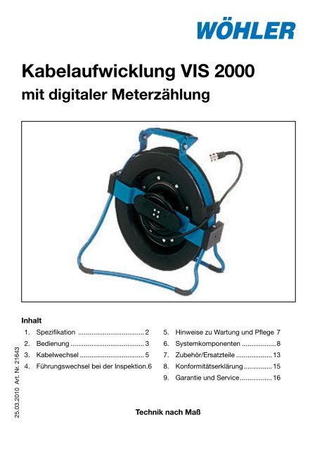
<strong>Kabelaufwicklung</strong> <strong>VIS</strong> <strong>2000</strong><br />
mit digitaler Meterzählung<br />
Inhalt<br />
1. Spezifikation ................................... 2<br />
2. Bedienung ....................................... 3<br />
3. Kabelwechsel .................................. 5<br />
4. Führungswechsel bei der Inspektion. 6<br />
5. Hinweise zu Wartung und Pflege 7<br />
6. Systemkomponenten ..................8<br />
7. Zubehör/Ersatzteile ...................13<br />
8. Konformitätserklärung ...............15<br />
9. Garantie und Service .................16<br />
Technik nach Maß
1. Spezifikation<br />
1. Spezifikation<br />
2 Hotline: 0 29 53 / 73 211 Fax: 0 29 53 / 73 250<br />
<strong>Kabelaufwicklung</strong> <strong>VIS</strong> <strong>2000</strong><br />
Das Videoinspektionssystem <strong>VIS</strong> <strong>2000</strong> ermöglicht die optische Kontrolle und<br />
Dokumentation in Rohren und Schächten, z.B. Abgasanlagen, Lüftungsanlagen,<br />
Abwasserrohren, etc. Das breite Spektrum der untereinander kompatiblen Systemkomponenten<br />
bietet die Auswahl einer individuellen und sehr gut auf die jeweilige<br />
Aufgabe abgestimmten Kamerazusammenstellung.<br />
Die hier beschriebene <strong>Kabelaufwicklung</strong> <strong>VIS</strong> <strong>2000</strong> dient dem bequemen Transport<br />
und der komfortablen Handhabung des bis zu 30 m langen Kamerakabels während<br />
der Inspektion.<br />
Darüber hinaus bietet die <strong>Kabelaufwicklung</strong> eine für Transport und Inspektion verstellbare<br />
Halterung zur Aufnahme der Monitor- und Steuereinheit, eine integrierte<br />
digitale Meterzählung zur Kabellängenmessung, einen komfortablen 4-Punkt-Tragegurt,<br />
eine Kabelbremse sowie einen Klappfuß. Sie ist hervorragend einzusetzen<br />
bei der Inspektion von vertikalen Rohrleitungen wie Schornsteinen oder Fallrohren<br />
und von Schächten etc. von oben. Mit heruntergeklappter Monitoreinheit inkl.<br />
Kamerakopf-Köcher sowie eingeklapptem Fuß entsteht eine kompakte, vollständige<br />
Videoinspektionseinheit, die am Traggriff oder mittels Tragegurt bequem zum<br />
Einsatzort transportiert werden kann. Mittels 4-Punkt-Tragegurt kann die Einheit<br />
vor Ort mit ausgeklapptem Monitor vor dem Körper getragen werden, so dass beide<br />
Hände für die Bedienung von Monitor und Kabel/Kamerakopf frei bleiben. Zur<br />
Bedienung auf dem Tisch oder dem Boden kann der Klappfuß breit ausgeklappt<br />
werden, so dass ein sicherer Stand erreicht wird. Eine eingebaute Kabelbremse<br />
dient der Sicherung des Kamerakopfes am Kabel.<br />
Die integrierte Meterzählung mit einer hohen Auflösung von 0,05 Metern und einer<br />
NullTaste ermöglicht eine genaue Positionsbestimmung der Schadstelle sowie<br />
Abstandsmessungen im Rohr.<br />
1.2 Technische Daten<br />
Maße zusammengeklappt:<br />
Höhe: 34 cm<br />
Breite: 35 cm<br />
Tiefe: 10 cm<br />
Gewicht: 2,5 kg (ohne Kabel)<br />
Max. Kabellänge: 30 cm<br />
Integrierte Meterzählung:<br />
Funktionsprinzip: digital<br />
Auflösung: 0,05 m<br />
Messbereich: 0 - 30,00 m<br />
Bedien-Taste: Nullstellung, Parametereingabe<br />
Bereitschaftsanzeige: LED
2. Bedienung<br />
2. Bedienung<br />
2.1 Bedienelemente<br />
5<br />
3<br />
9<br />
1<br />
Abbildung 2.1 Foto Foto<br />
ändern<br />
4 7<br />
2.2 Handhabung des Gerätes<br />
2.2.1 Anschluss der Kameraköpfe<br />
2<br />
10<br />
6<br />
9<br />
8<br />
1 Bedientaste<br />
<strong>Kabelaufwicklung</strong> <strong>VIS</strong> <strong>2000</strong><br />
(Nullstellung während der<br />
Messung, Parametereinstellung<br />
bei Einziehung eines<br />
neuen Kabels)<br />
2 Kabeltrommel<br />
3 Klappfuß<br />
4 Monitorhalterung mit Klapp-<br />
möglichkeit<br />
5 Traggriff<br />
6 Bremse (Rückseite)<br />
7 Anschlussmöglichkeit<br />
4-Punkt-Gurt<br />
8 Kabelanschluss zum Monitor<br />
9 Befestigung Monitoranschluss<br />
kabel (Rückseite Mitte)<br />
10 Einstellknopf zum Ändern der<br />
Position der Monitorhalterung<br />
Alle Kameraköpfe verfügen über eine 8-polige Kupplungs-Buchse, über die sie<br />
mit dem Kamerakabel der <strong>Kabelaufwicklung</strong> verbunden werden (8-poliger Kabelstecker).<br />
Stecken Sie die Kupplungs-Buchse des Kamerakopfes auf den Kabelanschluss<br />
des Kamerakabels und drehen Sie anschließend das Gewindestück an der <strong>Kabelaufwicklung</strong><br />
zum Verschließen im Uhrzeigersinn.<br />
2.2.2 Anschluss der Monitore<br />
Zum Anschließen des Monitors klappen Sie zunächst die Monitorhalterung hoch<br />
(Abbildung 1, Teil 4). Drücken Sie hierzu den Einstellknopf. (Abbildung 1, Teil 10).<br />
Verbinden Sie nun die Monitorhalterung mit dem Stativanschluss des Monitors.<br />
Danach verbinden Sie den Kabelanschluss der <strong>Kabelaufwicklung</strong> (Abb.1, Teil 8)<br />
mit der Eingangsbuchse am Monitor.<br />
e-mail: mgkg@woehler.de Internet: http://mgkg.woehler.<br />
3<br />
DEUTSCH
2. Bedienung<br />
2.2.3 Inspektion vertikaler Rohrleitungen<br />
4 Hotline: 0 29 53 / 73 211 Fax: 0 29 53 / 73 250<br />
<strong>Kabelaufwicklung</strong> <strong>VIS</strong> <strong>2000</strong><br />
Rohrleitungen wie Schornsteine oder Fallrohre lassen sich am besten von oben,<br />
z.B. vom Dach aus inspizieren. Hierfür ist die <strong>Kabelaufwicklung</strong> ideal geeignet. Um<br />
beide Hände frei zu haben, können Sie sie während der Inspektion vor dem Körper<br />
tragen, indem sie den 4-Punkt-Tragegurt an den dafür vorgesehenen Stellen der<br />
Aufwicklung befestigen. Klemmen Sie dazu die beiden schmalen Karabinerhaken<br />
in die Aufnahmen links und rechts unterhalb des Tragegriffes. Die beiden runden<br />
Karabinerhaken sind am Klappfuß zu befestigen, und zwar so, dass die rote Resettaste<br />
auf der Trommel zum Körper getragen wird. Dann hängen Sie sich die Gurte<br />
über die Schultern, so dass Sie das Kunststoffteil im Rücken tragen. Sie haben nun<br />
mit samt dem Gerät optimale Bewegungsfreiheit und können dabei das Display<br />
jederzeit auch inklusive Blendschutz bequem einsehen.<br />
Ist es nicht notwendig, die Position der <strong>Kabelaufwicklung</strong> und des Betrachters<br />
während der Inspektion zu ändern, bietet es sich an, die Aufwicklung für die Inspektion<br />
auf einem Tisch oder auf dem Boden abzustellen. Hierzu ist der Klappfuß<br />
auszuklappen.<br />
Nachdem Sie die Kabelaufaufwicklung in die für die jeweils anstehende Aufgabe<br />
günstigste Position gebracht haben, lösen sie die Trommelbremse durch eine halbe<br />
Umdrehung des schwarzen Drehknopfes. Drehen Sie den Knopf zum Lösen der<br />
Bremse nach links. Sie können nun das Kabel mit dem Kamerakopf in das Rohr<br />
herunterlassen. Wollen sie eine Stelle im Rohr genauer inspizieren, stellen sie die<br />
Bremse durch Rückdrehen des Drehknopfes wieder fest.<br />
Während des Transports ist die Trommelbremse grundsätzlich festzustellen. Der<br />
Klappfuß und die Monitorhalterung sind einzuklappen
3. Kabelwechsel<br />
2.3 Digitale Meterzählung<br />
<strong>Kabelaufwicklung</strong> <strong>VIS</strong> <strong>2000</strong><br />
In der <strong>Kabelaufwicklung</strong> ist eine digitale Meterzählung integriert, so dass die<br />
Position der Schadstelle während der Inspektion genau bestimmt werden<br />
kann und außerdem eine genaue Abstandsmessung im Rohr möglich ist. Die<br />
Betriebsbereitschaft der Meterzählung wird durch eine grüne LED angezeigt,<br />
die aufleuchtet, sobald der Kamerakopf eingeschaltet ist. Das Ergebnis der<br />
Meterzählung ist auf dem Monitor abzulesen. Dazu ist ggf. das Bildschirmmenü<br />
des Monitors entsprechend zu konfigurieren.<br />
Eine Bedientaste ermöglicht es, die Meterzählung an beliebiger Position, z.B. am<br />
Schornsteineingang, auf Null zu setzen. Der Weg des Kabels bis zum Schornsteineingang<br />
wird so nicht mitgezählt, und die genaue Position der Schadstelle im<br />
Schacht wird angegeben. Zur Abstandsmessung setzen sie die Metrierung beim<br />
Ausgangspunkt auf Null (durch Halten des Tasters an der Aufwicklung ca. 2 Sek.)<br />
und lesen dann bequem am Endpunkt den Abstand ab.<br />
3. Kabelwechsel<br />
Zum Austausch des Kabels ist zunächst die Bremse zu lösen. Das Kabel muss<br />
dann vorsichtig bis zum Ende herausgezogen werden. Lösen Sie nun die<br />
Steckverbindung zwischen Kabel und Kabelführung und nehmen Sie das Kabel<br />
heraus.<br />
Drehen Sie anschließend die <strong>Kabelaufwicklung</strong> im Uhrzeigersinn knapp eine Drehung<br />
vorsichtig bis zum Anschlag zurück. Führen Sie die Kupplungsbuchse des neuen<br />
Kabels durch die Öse zur Steckeraufnahme und verbinden Sie sie mit dem Stecker<br />
der <strong>Kabelaufwicklung</strong>. Jetzt können sie das Kabel linksherum aufwickeln. Beim<br />
Hereinschieben des Kabels sollte darauf geachtet werden, dass es sich gleichmäßig<br />
über die Breite der Kabeltrommel aufwickelt.<br />
Stellen Sie die Trommelbremse wie unter Punkt 2.2.3 beschrieben fest.<br />
Sollte ein Kabel anderer Länge eingesetzt worden sein, ist eine Neuprogrammierung<br />
der Parameter notwendig. Dazu halten Sie die Bedientaste der <strong>Kabelaufwicklung</strong><br />
ca. 3 Sekunden lang gedrückt und schalten den Monitor ein. Es erscheint oben eine<br />
Zeile mit Parametern. Mit Doppelklick auf die Bedientaste der <strong>Kabelaufwicklung</strong><br />
lässt sich der blinkende Cursor nach rechts bewegen, mit Einmalklick der Zähler<br />
verändern. Abspeichern lassen sich die Werte mit einem 3s Dauerklick. Anschließend<br />
werden die aktuellen Parameter neu angezeigt. Die Parameter müssen nach<br />
folgender Tabelle eingestellt werden:<br />
e-mail: mgkg@woehler.de Internet: http://mgkg.woehler.<br />
5<br />
DEUTSCH
4. Führungshilfen bei der Inspektion<br />
Typ Länge Impulse Da Di<br />
K-Aufw. 20m 695 24 19<br />
K-Aufw. 30m 1042 27 19<br />
K-Haspel 42 20m 382 42 38<br />
K-Haspel 42 30m 573 42 36<br />
K-Haspel 36 20m 561 36 32<br />
K-Haspel 36 30m 868 36 30<br />
4. Führungshilfen bei der Inspektion<br />
6 Hotline: 0 29 53 / 73 211 Fax: 0 29 53 / 73 250<br />
<strong>Kabelaufwicklung</strong> <strong>VIS</strong> <strong>2000</strong><br />
Im Folgenden sollen einige allgemeine Empfehlungen zum Einsatz von Führungshilfen<br />
bei der Inspektion von Rohren und Schächten gegeben werden, die wir aus<br />
unserer bisherigen Erfahrung gewonnen haben. Da jedes Rohr- und Schachtsystem<br />
individuell verschieden ist, muss natürlich in jedem Einzelfall vor Ort über<br />
die Benutzung der Hilfen entschieden werden. Bei der Auswahl der geeignetsten<br />
Führungshilfe ist zu beachten, dass diese neben einer guten Führung ein problemloses<br />
Hineinschieben wie Hinausziehen des Kamerakopfes gewährleisten muss.<br />
Die Gefahr eines möglichen Verklemmens oder Verhakens der Führungshilfe im<br />
Rohr ist zu berücksichtigen.<br />
Inspektion eines Rohres Ø 40 - 50 mm Benutzen Sie das Videoinspektionssystem<br />
immer ohne Zubehör.<br />
Inspektion eines Rohres Ø 50 -70 mm Benutzen Sie das Videoinspektonssystem<br />
immer ohne Zubehör.<br />
Verwenden Sie die Schubhüle ausschließlich<br />
im waagerechten Teil, wenn<br />
Wasser oder Schlick vorhanden ist.<br />
Inspektion eines Rohres Ø 70 - 100<br />
mm<br />
Inspektion eines Rohres Ø 100 - 125<br />
mm<br />
Die Inspektion ist problemlos mit und<br />
ohne Schubhülse möglich. Für Fallrohre<br />
oder für die vertikale Inspektion ist ein<br />
Führungsgewicht zu nutzen.<br />
Es können ein Zentrierstern und/oder<br />
eine Schubhüle bzw. eine Schubhülse<br />
mit Objektivschutz genutzt werden.<br />
Inspektion eines Rohres ab Ø 154 Siehe oben, allerdings ist der Kamerakopf<br />
nur wenige Meter zu schieben.
5. Wartung und Pflege<br />
5. Hinweise zu Wartung und Pflege<br />
<strong>Kabelaufwicklung</strong> <strong>VIS</strong> <strong>2000</strong><br />
Verschmutzungen am Kabel lassen sich entfernen, indem Sie das Kabel durch<br />
ein feuchtes Tuch ziehen. Reinigen Sie auch die <strong>Kabelaufwicklung</strong> mit einem<br />
feuchten Tuch und ggf. einem milden Reinigungsmittel. Achten Sie dabei unbedingt<br />
darauf, dass kein Wasser in den Bereich der Meterzählung dringt.<br />
Achtung: Das Gerät ist vor dem Öffnen von jeglicher Spannungsquelle<br />
(Monitoreinheit etc.) zu trennen. In jedem Fall sollten Arbeiten an der <strong>Kabelaufwicklung</strong><br />
nur von einem von Wöhler zugelassenen Fachbetrieb vorgenommen<br />
werden.<br />
6. Systemkomponenten<br />
Zur Anpassung an die jeweilige Inspektionsaufgabe bietet das Videoinspektionssystem<br />
<strong>VIS</strong> <strong>2000</strong> eine Vielzahl verschiedener, untereinander kompatibler Bausteine<br />
im Bezug auf die Auswahl von:<br />
• Monitor- und Steuereinheit<br />
• Kamerakopf<br />
• Verbindungskabel / -stange<br />
• Zubehör<br />
Durch Kombination der Module kann für die jeweilige Aufgabe die optimale Ausstattung<br />
zusammengestellt werden. Auch spätere Ergänzungen des Systems im<br />
Hinblick auf neue Aufgaben sind jederzeit möglich<br />
Abb. 2 zeigt die verschiedenen Komponenten im Überblick. Auf den nachfolgenden<br />
Seiten werden diese inkl. des zusätzlich erhältlichen Zubehörs kurz beschrieben.<br />
e-mail: mgkg@woehler.de Internet: http://mgkg.woehler.<br />
7<br />
DEUTSCH
6. Systemkomponenten<br />
Abbildung 6.1: Systemkomponenten<br />
8 Hotline: 0 29 53 / 73 211 Fax: 0 29 53 / 73 250<br />
<strong>Kabelaufwicklung</strong> <strong>VIS</strong> <strong>2000</strong>
6. Systemkomponenten<br />
6.1 Farbmonitor <strong>VIS</strong> <strong>2000</strong> (Best.-Nr. 7915 J)<br />
Der Farbmonitor ist kompatibel zu folgenden Kameraköpfen:<br />
-Miniatur-Kamerakopf Farbe<br />
-Kamerakopf <strong>VIS</strong> <strong>2000</strong> Farbe<br />
-Kamerakopf <strong>VIS</strong> 98 s/W<br />
- Endoskop-Kamerakopf<br />
-Miniatur-Kamerakopf s/w<br />
6.2 Farbmonitor <strong>VIS</strong> <strong>2000</strong> PRO (Best.-Nr. 6836 J)<br />
<strong>Kabelaufwicklung</strong> <strong>VIS</strong> <strong>2000</strong><br />
Der Farbmonitor <strong>VIS</strong> <strong>2000</strong> ist ein kompakter,<br />
leichter Monitor, der in einer Ledertasche<br />
mit Blendschutz und Tragegurt<br />
vor dem Körper getragen werden kann.<br />
Im Menü werden Datum, Uhrzeit, ein<br />
beweglicher Cursor sowie ein Titel mit<br />
10 Zeichen eingeblendet.<br />
Mit dem Farbmonitor <strong>VIS</strong> <strong>2000</strong>PRO ist<br />
es jetzt möglich, einzelne Bilder, wie<br />
auch Video-Sequenzen digital über den<br />
integrierten Karten Slot auf eine CF-<br />
Speicherkarte aufzunehmen. Die gespeicherten<br />
Bilder (.jpg) und Videosequenzen<br />
(.mov) können direkt vom Monitor über<br />
die CF-Speicherkarte leicht auf einen PC<br />
ausgelesen werden. Die integrierte Menüeinblendung<br />
stellt Längenanzeige, Darum<br />
und Uhrzeit als auch einen Titel am großen<br />
Farb-TFT-Display dar.<br />
Der Farbmonitor ist kompatibel zu folgenden Kameraköpfen:<br />
- Miniatur-Kamerakopf Farbe<br />
- Kamerakopf <strong>VIS</strong> <strong>2000</strong> Farbe<br />
- Kamerakopf <strong>VIS</strong> 98 s/W<br />
- Endoskop-Kamerakopf<br />
e-mail: mgkg@woehler.de Internet: http://mgkg.woehler.<br />
9<br />
DEUTSCH
6. Systemkomponenten<br />
6.3 Miniatur Kamerakopf <strong>VIS</strong> <strong>2000</strong> Farbe (Best.-Nr. 7817 J)<br />
Miniatur-Kamerakopf schwarz-weiß (Best.-Nr. 7871 J)<br />
6.4 Kamerakopf <strong>VIS</strong> <strong>2000</strong> Farbe (Best.-Nr. 7806 J)<br />
10 Hotline: 0 29 53 / 73 211 Fax: 0 29 53 / 73 250<br />
<strong>Kabelaufwicklung</strong> <strong>VIS</strong> <strong>2000</strong><br />
Der Miniatur Kamerakopf ist ein bis zu 3 bar<br />
wasserdichter Kamerakopf im robusten Edelstahlgehäuse,<br />
der über ein Weitwinkelobjektiv<br />
(f 2,5 mm) verfügt.<br />
Aufgrund seines kleinen Durchmessers von nur<br />
26 mm, der kurzen Baulänge und der robusten<br />
flexiblen Stangenanbindung lässt sich der Miniatur<br />
Kamerakopf auch in engen Leitungen<br />
durch mehrere Bögen hindurch problemlos<br />
einsetzen.<br />
Anwendung: Der Miniatur-Kamerakopf ist hervorragend<br />
geeignet zur optischen Inspektion<br />
und Kontrolle von Kanälen, Rohren, Abgasleitungen,<br />
Lüftungsleitungen und Ringspalte mit<br />
Durchmessern von ca. 40 mm bis 100 mm.<br />
Speziell der Miniatur Kamerakopf s/w ist durch<br />
seine außerordentliche Lichtempfindlichkeit<br />
auch für die Kontrolle von Schornsteinen bis 20<br />
x 20 cm und Abgasleitungen bis 30 cm Durchmesser<br />
geeignet.<br />
Die Kameraköpfe <strong>VIS</strong> <strong>2000</strong> Farbe und <strong>VIS</strong><br />
98 s/w sind spritzwassergeschützt durch ein<br />
vollständig gekapseltes Alugehäuse. Das Objektiv<br />
ist jeweils unter der Glaskuppel um 180°<br />
schwenkbar und um 360° drehbar. Durch zuschaltbare<br />
helle Lichtkörper kann der Fernbereich<br />
ausgeleuchtet werden. Der Kamerakopf<br />
ist mit einem Weitwinkelobjektiv (f = 2,0 mm)<br />
ausgestattet.<br />
Anwendung: Die Kameraköpfe sind hervorragend<br />
geeignet zur Dokumentation von Schäden<br />
und zur Kontrolle in Abgas- und Lüftungsanlagen<br />
sowie zur vorbereitenden Inspektion<br />
bei Sanierungsarbeiten an Abgasanlagen ab<br />
einem Durchmesser von ca. 70 mm.
6. Systemkomponenten<br />
6.5 Endoskop Kamerakopf Farbe (Best.-Nr. 8697 J)<br />
6.6 Video Inspektionssystem-Zubehör<br />
<strong>Kabelaufwicklung</strong> <strong>VIS</strong> <strong>2000</strong><br />
Der Endospop Kamerakopf Farbe wird vor<br />
allem zur Dokumentation endoskopischer<br />
Aufnahmen für die gutachterliche Tätigkeit<br />
eingesetzt. Außerdem ermöglicht er<br />
die Visualisierung des Endoskopbildes für<br />
mehrere Betrachter.<br />
Die Kamerahalterung ist mit einem<br />
Verbindungskabel und einem Gewinde<br />
M10 ausgestattet und kann so bequem<br />
auf alle GFK-Stangen montiert werden.<br />
Sie ist sowohl bei der vertikalen als<br />
auch bei der horizontalen Inspektion<br />
einsetzbar. Der Kamerakopf wird im<br />
Schutzkorb mit Blickrichtung nach unten<br />
hinten positioniert, so dass einfallendes<br />
Tageslicht bei der Inspektion von<br />
Schornsteinen nicht blendet.<br />
e-mail: mgkg@woehler.de Internet: http://mgkg.woehler. 11<br />
DEUTSCH
6. Systemkomponenten<br />
6.6.2 Kamerafederführung (Best.-Nr. 8633 J)<br />
6.6.3 Kamerahaspel (Best.-Nr. 7308 J, 7309 J, 7307 J)<br />
12 Hotline: 0 29 53 / 73 211 Fax: 0 29 53 / 73 250<br />
<strong>Kabelaufwicklung</strong> <strong>VIS</strong> <strong>2000</strong><br />
Die Kamerafederführung erleichtert<br />
die Führung des Kamerakopfes<br />
am Kabel in vertikalen<br />
Kanälen, indem sie das Verdrehen<br />
und Pendeln des Kopfes verhindert.<br />
Die Feder ist auf die jewei-<br />
Die Kamerahaspel wird mit Kamerastangen<br />
von 6 oder 7 mm l und<br />
einer Länge bis zu 30 m angeboten.<br />
Die Stange erlaubt die komfortable<br />
Inspektion vertikal wie auch horizontal<br />
verlaufender Rohrsysteme.<br />
6.6.4 Stabilisierungshülse mit Leinsternhalter (Best.-Nr. 3590 J)<br />
Zur Stabilisierung der Kameraköpfe<br />
<strong>VIS</strong> <strong>2000</strong> auf den Kamerastangen<br />
beim Durchstoßen großer Leitungen;<br />
einschraubbar in den Kamerakopf, die<br />
Rollenführung oder die Kameraführung;<br />
Zur Führung beim Herabstoßen,<br />
z.B. im Schonrstein, kann ein Leinstein<br />
aufgesteckt werden (nicht im LIeferumfang<br />
enthalten)
7. Zubehör<br />
6.6.5 LED Zusatzbeleuchtung (Best.-Nr. 9377 P und 9177 P)<br />
6.6.6 Digitaler Bildwandler (Best.-Nr. 6233 J)<br />
7. Zubehör/Ersatzteile zur <strong>Kabelaufwicklung</strong> Vis <strong>2000</strong><br />
7.1 Teleskop-Rollbock (Best.-Nr. 5706 L)<br />
<strong>Kabelaufwicklung</strong> <strong>VIS</strong> <strong>2000</strong><br />
Die LED Zusatzbeleuchtung mit<br />
rot-gelben und mit weißen LEDs zur<br />
Arbeit mit den Kameraköpfen <strong>VIS</strong> 98<br />
und <strong>2000</strong> ermöglicht die Ausleuchtung<br />
des Fernbereiches während der<br />
Inspektion. Die Zusatzbeleuchtung<br />
lässt sich einfach auf den Kamerakopf<br />
Mit Hilfe des digitalen Bildwandlers<br />
können Bilder über eine USB-Schnittstelle<br />
auf ein Notebook oder einen PC<br />
gespeichert werden.<br />
Mit dem Teleskop-Rollbock lässt<br />
sich der Kamerakopf am Kabel<br />
kontrolliert herablassen. Da er aus<br />
Edelstahl hergestellt ist, ist er besonders<br />
leicht und stabil. Er ist von<br />
22 auf 40 cm ausziehbar.<br />
e-mail: mgkg@woehler.de Internet: http://mgkg.woehler. 13<br />
DEUTSCH
7. Zubehör<br />
7.2 Transportkoffer XXL (Best.-Nr. 5824 L)<br />
7.3 Ersatzkabel<br />
14 Hotline: 0 29 53 / 73 211 Fax: 0 29 53 / 73 250<br />
<strong>Kabelaufwicklung</strong> <strong>VIS</strong> <strong>2000</strong><br />
mit Schultergurt. Garantiert den<br />
sicheren Transport der Kabelführung<br />
samt Zubehör<br />
30 m Kamerakabel mit Metrierung Best.-Nr. 7812 L<br />
20 m Kamerakabel mit Metrierung Best.-Nr. 9172 L<br />
7.5 Verlängerungskabel (Best.-Nr. 8636 L)<br />
10 m Verlängerungskabel mit Metrierung<br />
7.4 Tragegurt (Best.-Nr. 8136 I)<br />
Ermögicht es, die <strong>Kabelaufwicklung</strong><br />
bequem vor dem Körper zu tragen,<br />
so dass beide Hände für die Arbeiten<br />
frei bleiben
8. Konformitätserklärung<br />
8. EG-Konformitätserklärung<br />
Für das folgend bezeichnete Produkt<br />
9. Garantie und Service<br />
9.1 Garantie<br />
Videoinspektionsgerät <strong>VIS</strong> <strong>2000</strong><br />
<strong>Kabelaufwicklung</strong> <strong>VIS</strong> <strong>2000</strong><br />
wird hiermit bestätigt, dass es den wesentlichen Schutzanforderungen entspricht,<br />
die in den Richtlinien des Rates zur Angleichung der Rechtsvorschriften der Mitgliedstaaten<br />
über die elektomagnetische Verträglichkeit (2004/108/EG) festgelegt<br />
sind.<br />
Zur Beurteilung des Produkts hinsichtlich der elektromagnetischen Verträglichkeit<br />
wurden folgende Normen herangezogen:<br />
EN 55024 Störfestigkeit<br />
EN 55022 Störaussendung<br />
Dieser Erklärung wird verantwortlich für den Hersteller/Importeur<br />
Adresse:<br />
abgegeben durch:<br />
Wöhler Messgeräte Kehrgeräte GmbH<br />
Schützenstr. 38, D-33181 Bad Wünnenberg<br />
Dipl.-Phys. Johannes Lötfering, Geschäftsführer<br />
Bad Wünnenberg, 28.10.2004<br />
Jeder Farbmonitor <strong>VIS</strong> <strong>2000</strong> wird im Werk in allen Funktionen geprüft und verlässt<br />
unser Werk erst nach einer ausführlichen Qualitätskontrolle.<br />
Bei sachgemäßem Gebrauch beträgt die Garantiezeit auf den Monitor 12 Monate.<br />
Ausgenommen sind Verschleißteile (wie z.B. Akkus/Batterien) und Verbrauchsmaterialien.<br />
Die Kosten für den Transport und die Verpackung des Geräts im Reparaturfall<br />
e-mail: mgkg@woehler.de Internet: http://mgkg.woehler. 15<br />
DEUTSCH
9. Garantie und Service<br />
16 Hotline: 0 29 53 / 73 211 Fax: 0 29 53 / 73 250<br />
<strong>Kabelaufwicklung</strong> <strong>VIS</strong> <strong>2000</strong><br />
werden von dieser Garantie nicht abgedeckt. Diese Garantie erlischt, wenn Reparaturen<br />
und Abänderungen von dritter, nicht autorisierter Stelle an dem Gerät<br />
vorgenommen wurden.<br />
Der SERVICE wird bei uns sehr groß geschrieben. Deshalb sind wir auch selbstverständlich<br />
nach der Garantiezeit für Sie da.<br />
• Es erfolgt eine sofortige Reparatur, wenn Sie mit Ihrem Gerät zu uns nach<br />
Bad Wünnenberg kommen.<br />
• Sie schicken das Gerät zu uns, wir reparieren es innerhalb weniger Tage<br />
und schicken es Ihnen mit unserem Paketdienst.<br />
• Sie erhalten gegen einen geringen Pauschalbetrag ein Leihgerät gestellt.<br />
• Sofortige Hilfe erhalten Sie durch unsere Techniker am Telefon.
9. Garantie und Service<br />
Verkaufs- und Servicestellen<br />
Deutschland<br />
Wöhler Messgeräte Kehrgeräte<br />
GmbH<br />
Schützenstr. 41<br />
33181 Bad Wünnenberg<br />
Tel.: +49 2953 73-100<br />
Fax: +49 2953 73-250<br />
mgkg@woehler.de<br />
http://mgkg.woehler.de<br />
Verkaufs- u. Servicestelle Süd<br />
Wöhler Messgeräte Kehrgeräte<br />
GmbH<br />
Gneisenaustr.12<br />
80992 München<br />
Tel.: +49 89 1589223-0<br />
Fax: +49 89 1589223-99<br />
sued@woehler.de<br />
International<br />
<strong>USA</strong><br />
<strong>Wohler</strong> <strong>USA</strong> Inc.<br />
20 Locust Street, Suite 205<br />
Danvers, MA 01923<br />
Tel.: +1 978 750 9876<br />
Fax.: +1 978 750 9799<br />
www.wohlerusa.<strong>com</strong><br />
Italien<br />
Wöhler Italia srl<br />
Corso Libertà 9<br />
39100 Bolzano<br />
Tel.: +390471402422<br />
Fax: +39 0471<br />
Verkaufs- u. Servicestelle Rhein/<br />
Ruhr<br />
Wöhler Messgeräte Kehrgeräte<br />
GmbH<br />
Castroper Str. 105<br />
44791 Bochum<br />
Tel.: +49 234 516993-0<br />
Fax: +49 234 516993-99<br />
rheinruhr@woehler.de<br />
Tschechien<br />
Wöhler Bohemia s.r.o.<br />
Za Naspern 1993<br />
393 01 Pelhrimov<br />
Tel.: +420 5653 49019<br />
Fax: +420 5653 23078<br />
info@woehler.cz<br />
<strong>Kabelaufwicklung</strong> <strong>VIS</strong> <strong>2000</strong><br />
e-mail: mgkg@woehler.de Internet: http://mgkg.woehler. 17<br />
DEUTSCH
9. Garantie und Service<br />
18 Hotline: 0 29 53 / 73 211 Fax: 0 29 53 / 73 250<br />
<strong>Kabelaufwicklung</strong> <strong>VIS</strong> <strong>2000</strong>
<strong>VIS</strong> <strong>2000</strong> Cable reel<br />
with digital metric marking<br />
Contents<br />
1. Specification .............................19<br />
2. Operation ...................................20<br />
3. Changing the cable ...................22<br />
4. Maintenance ..............................23<br />
5. System Components .................23<br />
6. Accessories ...............................29<br />
7. Declaration of conformity ..........30<br />
8. Guarantee and Service ..............31<br />
The Measure of Technology
1. Specification<br />
1. Specification<br />
20 Hotline: 0 29 53 / 73 211 Fax: 0 29 53 / 73 250<br />
Cable reel <strong>VIS</strong> <strong>2000</strong><br />
The video inspection system is ideal for the optical control and examination of horizontally<br />
and vertically running exhaust systems (modern chimneys) as well as for<br />
sewers and ventilation systems with a diameter from 6 to 30 cm. The <strong>com</strong>patible<br />
system <strong>com</strong>ponents offer various individual solutions which are perfectly convenient<br />
for the corresponding job.<br />
The cable reel described in this manual is used for the transport and the handling<br />
of camera cables up to 30 m during the inspection. It <strong>com</strong>es with a support for the<br />
monitor for more <strong>com</strong>fortable inspection and an integrated digital metric marking<br />
for the measuring of the cable lenght, as well as a <strong>com</strong>fortable shoulder strap, a<br />
cable brake and a collapsable stand. It is perfectly applicable for the inspection of<br />
vertical pipings such as chimneys, downpipes and slots from above. By means of<br />
the foldable monitor support and the collapsable stand of the winder, the set is very<br />
<strong>com</strong>pact and can <strong>com</strong>fortably be transported. At work, the unit may be carried in<br />
front of the body by the 4-point-carrying-belt with the monitor in front of the body,<br />
so that both hands will be free for the operation of the monitor and the cable with<br />
the camera head. When the stand is <strong>com</strong>pletely unfolded, the cable reel can be<br />
placed on a table or on the floor. An integrated cable brake holds the camera head<br />
at the cable.<br />
The integrated metric marking with a high resolution of 0.05 meters and a zerosetting<br />
button enables an exact determination of the position of the defect as well<br />
as the measurement of distances in the duct.<br />
1.2 Tecnical Data<br />
Size, unfolded:<br />
Height: 34 cm<br />
Width: 35 cm<br />
Depth: 10 cm<br />
Weight: 2.5 kg (without cable)<br />
Max. cable length 30 m<br />
Integrated metric marking:<br />
Functional principle: digital<br />
Resolution: 0.05 m<br />
Measuring range: 0 - 30.00 m<br />
Operation button: Reset to zero, Input of parameters<br />
Standby: LED
2. Operation<br />
2. Operation<br />
2.1 Controls<br />
3<br />
5<br />
9<br />
1<br />
Figure 2.1 Foto Foto<br />
ändern<br />
4 7<br />
2.2 Operation of the device<br />
2.2.1 Connection of the camera heads<br />
Cable reel <strong>VIS</strong> <strong>2000</strong><br />
1 Operation button<br />
(Reset to zero during the measurment,<br />
input of parameters<br />
during the installation of the<br />
new cable )<br />
2 Cable reel<br />
3 Stand<br />
4 Collapsible monitor holder<br />
5 Grip<br />
6 Brake (back side)<br />
7 Connection for 4-point-belt<br />
8 Cable connection to the monitor<br />
9 Attachment of the monitor<br />
connection cable (Middle of<br />
the back side)<br />
10 Adjusting button for changing<br />
the position of the monitor<br />
support<br />
All camera-heads are connected via a clutch socket with 8 poles to the cable in<br />
the cable reel (cable jack with 8 poles).<br />
Plug camera head and camera cable together and then turn the thread<br />
clockwise for closing the screw connection tightly.<br />
2.2.2 Connection of the monitors<br />
2<br />
10<br />
6<br />
9<br />
First, unfold the monitor support while pressing the adjusting button. (Figure<br />
2.1, part 10). Now screw the monitor out of the monitor support. After that<br />
connect the cable connection of the cable reel (figure 2.1, part 8) to the video<br />
in-socket of the monitor.<br />
8<br />
e-mail: mgkg@woehler.de Internet: http://mgkg.woehler. 21<br />
ENGLISH
2. Operation<br />
2.2.3 Inspection of vertical pipings<br />
22 Hotline: 0 29 53 / 73 211 Fax: 0 29 53 / 73 250<br />
Cable reel <strong>VIS</strong> <strong>2000</strong><br />
Pipings, such as chimneys or downpipes, can be inspected best from above.<br />
The cable reel is ideal for that purpose. If you carry it in front of the body with the<br />
four-point carrying belt system, your hands will be free for working. First jam the<br />
two narrow snap-hooks in the two openings at the left and the right under the<br />
grip. The two round snap-hooks will be fixed to the stand, so that the red resetbutton<br />
on the reel shows to the body. This way you can move optimally and you<br />
are able to regard the display at every time.<br />
If it is not necesarry to change the position of the cable reel during the inspection,<br />
it will be best to put the cable reel on a table or on the floor while working. In this<br />
case you will have to unfold the stand.<br />
After having put the cable reel in the best position, release the brake by turning the<br />
knob at the reel half a rotation left. Now you can let the cable with the camera head<br />
down in the pipe. If you want to control a special point of the pipe in a more detailed<br />
way, you will have to fix the brake by turning the rotation button back.<br />
During transport the brake generally has to be fixed and the stand and the monitor<br />
holder must be folded.
2. Operation<br />
2.3 Digital Metric Marking<br />
Cable reel <strong>VIS</strong> <strong>2000</strong><br />
The cable reel has a digital metric marking integrated, so that the position of<br />
the defect can be exactly determined during the inspection and a distance<br />
measurement in the pipe will be possible. The green LED shows that the metric<br />
marking is ready for operation. The LED will shine as soon as the camera head is<br />
switched on. The result of the meter measurement will be shown in the monitor. If<br />
necessary, you will have to configurate the display menu correspondingly.<br />
A special button can reset the metric marking to zero in every position, for<br />
example at the chimney entry. The way of the camera until the entry of the<br />
chimney will not be included in the measurement and the exact position of the<br />
defect in the pipe will be shown. For measuring the distance, reset the metric<br />
marking to zero at the initial point (by pressing the operation button for two<br />
seconds) and then read off the distance at the end point.<br />
3. Changing the cable<br />
For changing the cable, first release the brake. Then pull the cable carefully out<br />
of the reel. Now disconnect the connection between cable and cable reel and<br />
take out the cable.<br />
Then carefully turn the cable reel clockwise almost one rotation back up to the<br />
stop position. Guide the jack of the new cable through the loop to the clutch<br />
socket and connect them. Now you can roll up the viper anticlockwise. While<br />
rolling up the cable, pay attention that it coils smooth around the reel.<br />
Fix the brake as described in point 2.2.3.<br />
If you insert a cable with another length, you will have to change the parameters.<br />
Press the operation button during about three seconds for switching on the<br />
monitor. The parameters will be shown in the first line. With a double-click on the<br />
operating button of the cable reel the blinking cursor can be moved to the right.<br />
Clicking once the counter can be changed. By pressing the button for three seconds,<br />
the value will be stored. After that the new parameters will be displayed.<br />
The parameters must be entered according to the following table:<br />
e-mail: mgkg@woehler.de Internet: http://mgkg.woehler. 23<br />
ENGLISH
4. Maintenance<br />
Type lenth running meters external dimension internal dim.<br />
Cable winder 20m 695 24 19<br />
Cable winder 30m 1042 27 19<br />
Camera viper 42<br />
38<br />
20m 382 42<br />
Camera viper 42<br />
36<br />
30m 573 42<br />
Camera viper 36 20m 561 36<br />
4.Maintenance<br />
24 Hotline: 0 29 53 / 73 211 Fax: 0 29 53 / 73 250<br />
Cable reel <strong>VIS</strong> <strong>2000</strong><br />
The cable can be cleaned by pulling it through a damp cloth. Clean the cable reel<br />
with a damp cloth only, but never with water and cleaning agent. Pay attention that<br />
no water will enter the metric marking.<br />
Attention: Before opening the device disconnect it from any voltage<br />
source. (e.g. monitor unit.) Only an authorized establishment should<br />
5. System Components<br />
The video-inspection-system <strong>VIS</strong> <strong>2000</strong> offers a great number of <strong>com</strong>patible <strong>com</strong>ponents<br />
to adapt the device to varios special tasks, that <strong>com</strong>ponents are.<br />
· monitor and control unit<br />
· camera head<br />
· connection cable/rod<br />
· accessories<br />
This way it is possible to <strong>com</strong>bine the perfect equipment for each task. You can<br />
also <strong>com</strong>plete the system later on for new tasks.<br />
Figure 5w.1 shows the different <strong>com</strong>ponents. On the next pages, the <strong>com</strong>ponents<br />
and their accessories are shortly described.
5. System Components<br />
5. System Components<br />
Figure 5.1: System Components<br />
Cable reel <strong>VIS</strong> <strong>2000</strong><br />
e-mail: mgkg@woehler.de Internet: http://mgkg.woehler. 25<br />
ENGLISH
5. System Components<br />
5.1 Camera head <strong>VIS</strong> <strong>2000</strong> Colour (Order no. 7806 J )<br />
Camera head <strong>VIS</strong> 98 b/w (Order no. 7801)<br />
5.2 Miniature camera head (Order no. 7817 J)<br />
Miniature camera head b/w (Order no. 7871 J )<br />
26 Hotline: 0 29 53 / 73 211 Fax: 0 29 53 / 73 250<br />
Cable reel <strong>VIS</strong> <strong>2000</strong><br />
The camera heads <strong>VIS</strong> <strong>2000</strong> colour and <strong>VIS</strong><br />
98 b/w are splashproof enclosed in an aluminium<br />
housing. They enable a simple and<br />
exact inspection by the 180 o tilt and 360 o pan<br />
function of the camera head. Extra LEDs for<br />
additional light make it possible to see even<br />
at far distances. The camera head <strong>com</strong>es<br />
with a wide angle objective (f=2.0 mm).<br />
Applications: Inspection and documentation<br />
of damage in ventilation and exhaust<br />
systems from aprox. 70 mm.<br />
The mini camera head is watertight up to 3<br />
bar and has a durable stainless steel housing<br />
with a wide angle objective (f=2.0 mm).<br />
Because of the small diameter of only 26<br />
mm, the short length and the flexible viper<br />
it can be used in small lines and pipes with<br />
various bows without problems.<br />
Applications: Inspection and direct documentation<br />
of flue lines and ventilations as<br />
well as water pipes with a diameter from 40<br />
mm to 100 mm.<br />
Especially the mini camera head black and<br />
white is extremely sensitive to light and<br />
therefore convenient for the control of chimneys<br />
up to 20 x 20 cm and flue lines up to<br />
30 cm Ø.
5. System Components<br />
5.3 Endoscope camera head colour (Order no. 8697 J )<br />
5.4 Assessories Video inspection<br />
5.4.1 Camera roller guide (Order no. 7826 J)<br />
Cable reel <strong>VIS</strong> <strong>2000</strong><br />
The Endoscope Camera Head color is used<br />
especially for the documentation of endoscopic<br />
snapshots for expertises. It also makes it<br />
possible that various persons can regard the<br />
endoscopic picturenon a monitor.<br />
Camera roller guide for the Camera head <strong>VIS</strong><br />
<strong>2000</strong> and <strong>VIS</strong> 98, for pushing the camera<br />
head in horizontally running exhaust systems<br />
and ventilation systems and chimneys.<br />
Advantages/Features:<br />
• guidance rolls<br />
• simple installation at the camera head<br />
• special steel protection, powder coated<br />
5.4.2 Stabilization sleeve with star holder (Order no. 3590 J)<br />
For the stabilization of the camera heads <strong>VIS</strong><br />
<strong>2000</strong> and <strong>VIS</strong> 98 on the camera viper when<br />
pushing through large pipes; it is simply<br />
screwed into the roller guide. When pushing<br />
downwards, for example in the chimney, a<br />
star can be plugged on for better guiding<br />
(not included in delivery).<br />
e-mail: mgkg@woehler.de Internet: http://mgkg.woehler. 27<br />
ENGLISH
5. System Components<br />
5.4.3 Telescope Dolly (Order no. 5706 L)<br />
28 Hotline: 0 29 53 / 73 211 Fax: 0 29 53 / 73 250<br />
Cable reel <strong>VIS</strong> <strong>2000</strong><br />
For letting down the camera head at the<br />
cable. Especially light and stable because<br />
of special steel. Extendable from 22 to 40<br />
cm.<br />
5.4.4 LED supplementary light (Order no. 9377 P und 9177 P)<br />
5.4.5 Camera viper (Order no. 7822 J )<br />
The LED supplementary light with red-yellow<br />
and white LEDs, for camera head <strong>VIS</strong> <strong>2000</strong><br />
and <strong>VIS</strong> 98 makes it possible to iluminate the<br />
distant zone during the inspection.<br />
The camera viper is available with a camera<br />
rod of 6 or 7mm diameter and a length of<br />
20.05 m. With the viper a <strong>com</strong>fortable inspection<br />
of horizontally and vertically running<br />
exhaust systems is possible.
5. System <strong>com</strong>ponents<br />
5.4.6 Viper Camera Holder (Order no. 8680 J)<br />
5.4.7 Camera Spring Guide (Order no. 8633 J)<br />
5.4.8 Special Cable (Order no. 9181 L)<br />
0.8 m, for the connection of the Camera rod to the monitor.<br />
5.4.9 Camera rod<br />
Cable reel <strong>VIS</strong> <strong>2000</strong><br />
The camera holder provides a connection<br />
cable and a M 10 thread and therefore can<br />
easily be connected to our cleaning rods.<br />
The camera is in a protective cage and faces<br />
down, so that incidental daylight does not<br />
cause problems. Attached to rods both, horizontal<br />
and vertical pipes can be examined.<br />
For centering of the camera head in vertical<br />
vents. A stainless steel spring prevents a<br />
rotating and oscillating of the camera head.<br />
The spring is adjustable to the tubing size.<br />
Camera rod black, flexible, 6 mm Ø, 5 m long (Order no. 7821 J)<br />
Camera rod black, flexible, 6 mm Ø, 20 m long (Order no. 7818 J)<br />
Camera rod black, flexible, 6 mm Ø, 30 m long (Order no. 7819 J)<br />
Camera rod red, stable, 7 mm Ø, 5 m long (Order no. 7305 J)<br />
Camera rod red, stable, 7 mm Ø, 20 m long (Order no. 7829 J)<br />
Camera rod red, stable, 7 mm Ø, 30 m long (Order no. 7306 J)<br />
e-mail: mgkg@woehler.de Internet: http://mgkg.woehler. 29<br />
ENGLISH
6. Accessories<br />
6. Accessories/Spare Parts of the Colour Monitor <strong>VIS</strong> <strong>2000</strong><br />
6.1 Power Supply <strong>VIS</strong> <strong>2000</strong> PRO (Order no. 6837 J)<br />
for mains operation and charging<br />
30 Hotline: 0 29 53 / 73 211 Fax: 0 29 53 / 73 250<br />
Cable reel <strong>VIS</strong> <strong>2000</strong><br />
6.2 Leather protection bag for monitor <strong>VIS</strong> <strong>2000</strong> PRO (Order no. 6838 J)<br />
6.3 Adaptercable (Order no. 8637 O)<br />
for the 12 volt car-system<br />
6.4 Shoulder strap (Order no. 8136 I)<br />
With glare protection and shoulder-strap. For<br />
the secure transport and a <strong>com</strong>fortable position<br />
of the monitor during the inspection.<br />
Makes it possible to carry the Cable reel<br />
<strong>com</strong>fortably in front of the body, so that both<br />
hands will be free for working.
7. Declaration of conformity<br />
7. Declaration of conformity<br />
Manufacturer: WÖHLER Messgeräte Kehrgeräte GmbH<br />
Schützenstr. 41, 33181 Bad Wünnenberg<br />
Cable reel <strong>VIS</strong> <strong>2000</strong><br />
declares that the following product:<br />
Product name: Wöhler <strong>VIS</strong> <strong>2000</strong> Cable reel<br />
<strong>com</strong>plies with key safety requirements set down in the guidelines of the Council<br />
for the Harmonisation of the Legal Requirements of the Member States in relation<br />
to electromagnetic <strong>com</strong>patibility (2004/108/CE).<br />
The following standards are used to assess the product in terms of electromagnetic<br />
<strong>com</strong>patibility:<br />
EN 55024 Resistance to jamming<br />
EN 55022 Emitted interference<br />
This declaration is issued on behalf of the aforementioned manufacturer by:<br />
Johannes Lötfering, Managing Director Bad Wünnenberg, 28.10.2004<br />
e-mail: mgkg@woehler.de Internet: http://mgkg.woehler. 31<br />
ENGLISH
8. Guarantee and Service<br />
8. Guarantee and Service<br />
8.1 Guarantee<br />
32 Hotline: 0 29 53 / 73 211 Fax: 0 29 53 / 73 250<br />
Cable reel <strong>VIS</strong> <strong>2000</strong><br />
Every Wöhler <strong>VIS</strong> <strong>2000</strong> cable reel has been subjected to a thorough functional<br />
check and only leaves our factory after detailed quality control. The final inspection<br />
is recorded in detail in a test report and is kept by us on our premises. If the device<br />
is used correctly, the guarantee period is 12 months from the date of purchase.<br />
This guarantee does not cover wear and tear parts.<br />
The guarantee does not include the costs for transport and packing material in case<br />
of repair. It will expire, if third persons, who are not authorized, repaire or change<br />
the device.<br />
We see SERVICE as a very important element in our business. That is why we are<br />
still available to you even after the guarantee period has expired.<br />
• An immediate repair will be carried out if you bring your meter to us in Bad<br />
Wünnenberg.<br />
• If you send us the meter, it will be returned to you by our delivery service<br />
after repair in just a few days.<br />
• We can lend you a device for a small standard fee.<br />
• You can obtain immediate help from our engineers by telephone
Sales and service sites<br />
Points of sale and service<br />
Germany<br />
Wöhler Messgeräte Kehrgeräte<br />
GmbH<br />
Schützenstr. 41<br />
33181 Bad Wünnenberg<br />
Tel.: +49 2953 73-100<br />
Fax: +49 2953 73-250<br />
mgkg@woehler.de<br />
http://mgkg.woehler.de<br />
Verkaufs- u. Servicestelle Süd<br />
Wöhler Messgeräte Kehrgeräte<br />
GmbH<br />
Gneisenaustr.12<br />
80992 München<br />
Tel.: +49 89 1589223-0<br />
Fax: +49 89 1589223-99<br />
sued@woehler.de<br />
International<br />
<strong>USA</strong><br />
<strong>Wohler</strong> <strong>USA</strong> Inc.<br />
20 Locust Street, Suite 205<br />
Danvers, MA 01923<br />
Tel.: +1 978 750 9876<br />
Fax.: +1 978 750 9799<br />
www.wohlerusa.<strong>com</strong><br />
Italy<br />
Wöhler Italia srl<br />
Corso Libertà 9<br />
39100 Bolzano<br />
Tel.: +390471402422<br />
Fax: +39 0471<br />
Verkaufs- u. Servicestelle Rhein/<br />
Ruhr<br />
Wöhler Messgeräte Kehrgeräte<br />
GmbH<br />
Castroper Str. 105<br />
44791 Bochum<br />
Tel.: +49 234 516993-0<br />
Fax: +49 234 516993-99<br />
rheinruhr@woehler.de<br />
Czech Republic<br />
Wöhler Bohemia s.r.o.<br />
Za Naspern 1993<br />
393 01 Pelhrimov<br />
Tel.: +420 5653 49019<br />
Fax: +420 5653 23078<br />
info@woehler.cz<br />
Your contact:<br />
Cable reel <strong>VIS</strong> <strong>2000</strong><br />
e-mail: mgkg@woehler.de Internet: http://mgkg.woehler. 33<br />
ENGLISH
Avvolgicavo <strong>VIS</strong> <strong>2000</strong><br />
con contametri digitale incorporato<br />
Indice<br />
1. Specificazione ............................. 36<br />
2. Uso ..............................................37<br />
3. Sostituzione del cavo ..................39<br />
4. Guide per l’ispezione ...................40<br />
Soluzioni tecniche su misura<br />
5. Indicazioni sulla manutenzione<br />
e la cura .......................................41<br />
6. Componenti del sistema .............41<br />
7. Certificato di conformità ..............47<br />
8. Garanzia: .....................................47
1. Specification<br />
1. Specificazione<br />
36 Tel: 0471 402422 Fax: 0471 406099<br />
Avvolgicavo <strong>VIS</strong> <strong>2000</strong><br />
Il sistema di videoispezione <strong>VIS</strong> <strong>2000</strong> permette il controllo visivo e la documentazione<br />
di tubi e canali, <strong>com</strong>e ad es. impianti di scarico, impianti di ventilazione,<br />
tubi acqua di rifiuto ecc. La vasta gamma di <strong>com</strong>ponenti di sistema, <strong>com</strong>patibili<br />
l’uno con l’altro, offre una scelta individuale per la <strong>com</strong>posizione della telecamera<br />
perfettamente adattabile al rispettivo <strong>com</strong>pito da svolgere.<br />
L’avvolgicavo <strong>VIS</strong> <strong>2000</strong> qui descritto serve per il trasporto <strong>com</strong>odo e per una maneggevolezza<br />
confortevole del cavo dotato di telecamera, la cui lunghezza massima<br />
è di 30 m, durante l ’ispezione. L’avvolgicavo offre inoltre un supporto regolabile<br />
per il trasporto e per l’ispezione per collocarvi l’unità del monitor e di <strong>com</strong>ando, un<br />
contametri digitale integrato per misurare la lunghezza del cavo, una cintura confortevole<br />
a 4 punti, un freno del cavo nonché un piede pieghevole. Si presta molto<br />
bene all’impiego dall’alto per l’ispezione di tubi verticali, <strong>com</strong>e per canne fumarie<br />
o per pluviali, pozzi ecc.. Con l’unità motore ribaltata verso il basso, <strong>com</strong>preso il<br />
contenitore della testata della telecamera e con il piede ribaltato si crea un’unità di<br />
videoispezione <strong>com</strong>patta e <strong>com</strong>pleta, che, usando la maniglia o la cintura, si può<br />
trasportare <strong>com</strong>odamente sul luogo d’impiego. Grazie alla cintura a 4 punti sul luogo<br />
è possibile trasportare l’unità davanti al proprio corpo con il monitor tratto fuori,<br />
di modo che entrambe le mani rimangano libere per l’uso del monitor e del cavo /<br />
della testata di telecamera. Per l’uso sul tavolo o sul pavimento si può ribaltare il<br />
piede pieghevole, in modo da ottenere una stabilità sicura. Un freno integrato del<br />
cavo serve ad assicurare la testata della telecamera sul cavo.<br />
Il contametri integrato di un’elevata risoluzione di 0,05 metri è dotato di un tasto di<br />
azzeramento che permette di individuare in modo preciso la posizione del danno<br />
permettendo inoltre misurazioni di distanza all’interno del tubo.<br />
1.2 Dati tecnici<br />
Dimensioni nello stato ripiegato:<br />
Altezza: 34 cm<br />
Larghezza: 35 cm<br />
Profondità: 10 cm<br />
Peso: 2,5 kg (senza cavo)<br />
Lunghezza max. cavo:<br />
Contametri integrato:<br />
30 m<br />
Funzionamento digitale<br />
Risoluzione: 0,05 m<br />
Campo di misura: 0 - 30,00 m<br />
Tasto di <strong>com</strong>ando: azzeramento, inserimento parametri<br />
Indicazione dispositivo pronto: LED
2. Uso<br />
2. Uso<br />
2.1 Elementi di <strong>com</strong>ando<br />
4 7<br />
5<br />
3<br />
9<br />
1<br />
Figura 2.1 Foto Foto<br />
ändern<br />
2.2 Manovra di unità<br />
2.2.1 Collegamento dei testata<br />
2<br />
10<br />
6<br />
9<br />
8<br />
1 Tasto di <strong>com</strong>ando<br />
e-mail: info@woehler.it www.woehler.it<br />
Avvolgicavo <strong>VIS</strong> <strong>2000</strong><br />
(azzeramento durante la<br />
misurazione, impostazione parametri<br />
per l’inserimento di un<br />
nuovo cavo)<br />
2 Tamburo per cavi<br />
3 Piede ribaltabile<br />
4 Supporto monitor con possibili<br />
tà di ribaltamento<br />
5 Maniglia<br />
6 Freno (sul retro)<br />
7 Possibilità di collegamento<br />
Cintura a 4 punti<br />
8 Collegamento cavo al monitor<br />
9 Fissaggio del cavo di collega<br />
mento monitor (retro centrale)<br />
10 Pulsante di impostazione per<br />
modificare la posizione del<br />
supporto monitor<br />
Scegliere l’avvolgicavo con il cavo rigido adatto per robustezza, raggio di curvatura<br />
e lunghezza<br />
Montare la testata adatta, scegliendo tra la minitestata colori o b/n a seconda<br />
delle esigenze (b/n vede meglio nelle canne fumarie).<br />
2.2.2 Collegamento dei monitor<br />
Per collegare il monitor, ribaltare innanzitutto il supporto del monitor verso l’alto<br />
(fig. 1, parte 4). Per farlo premere il pulsante d’impostazione (fig. 1, parte 10). Poi<br />
collegare il supporto monitor con la presa d’ingresso del piede del monitor.<br />
In seguito collegare la connessione dell’avvolgicavo (fig. 1, parte 8) con la presa<br />
d’ingresso sul monitor.<br />
37<br />
ITALIANO
2. Uso<br />
2.2.3 Ispezione di tubazioni verticali<br />
38 Tel: 0471 402422 Fax: 0471 406099<br />
Avvolgicavo <strong>VIS</strong> <strong>2000</strong><br />
Il modo migliore di ispezionare tubazioni verticali, <strong>com</strong>e ad es. canne fumarie o tubi<br />
verticali a gravità, è di farlo dall’alto, ad es. dal tetto. L’aspo infatti è perfettamente<br />
idoneo a questo proposito. Per avere libere entrambe le mani, durante l’ispezione<br />
stessa si può portare l’aspo davanti al proprio corpo, fissando la cintura a 4 punti<br />
sugli appositi punti dell’aspo. Fissare i due moschettoni stretti negli appositi alloggiamenti<br />
posizionati a sinistra ed a destra al di sotto della maniglia. I due moschettoni<br />
tondi vanno fissati sul piede ribaltabile in modo tale che il tasto rosso di reset venga<br />
portato sul tamburo verso il proprio corpo. Poi mettere le cinture sopra le proprie<br />
spalle, di modo che il <strong>com</strong>ponente in plastica sia situato sulla propria schiena. In<br />
tal modo con l’apparecchiatura si ha una libertà ottimale di movimento e si può<br />
vedere <strong>com</strong>odamente in qualsiasi momento il display anche con la protezione<br />
antiriflessi <strong>com</strong>presa.<br />
Se non è necessario cambiare la posizione dell’aspo e dell’operatore durante<br />
l’ispezione, è opportuno appoggiare per l’ispezione l’aspo su un tavolo oppure sul<br />
pavimento. Per farlo, ribaltare il piede all’infuori.<br />
Dopo aver posto l’avvolgicavo nella posizione idonea per il <strong>com</strong>pito da svolgere,<br />
sbloccare il freno del tamburo effettuando metà giro con la manopola nera. Per<br />
sbloccare il freno girare la manopola verso la sinistra. Ora si può introdurre nel<br />
tubo verso il basso il cavo insieme alla testata della telecamera. Se si desidera<br />
ispezionare in modo più preciso un determinato punto del tubo, bloccare di nuovo<br />
il freno girando di nuovo indietro la manopola.<br />
Durante il trasporto, in via di principio il freno del tamburo va sempre bloccato. Il<br />
piede ribaltabile ed il supporto del monitor vanno ribaltati verso l’interno.
3. Sostituzione del cavo<br />
2.3 Contametri digitale<br />
e-mail: info@woehler.it www.woehler.it<br />
Avvolgicavo <strong>VIS</strong> <strong>2000</strong><br />
Nell’aspo è incorporato un contametri digitale, in modo da poter determinare<br />
con precisione durante l’ispezione la posizione del danno e per consentire inoltre<br />
una misurazione precisa delle distanze all’interno del tubo. Un LED verde indica<br />
che il contametri è pronto al funzionamento, il LED si illumina non appena la<br />
testata della telecamera è stata inserita. Il risultato del contametri si può leggere<br />
sul monitor. In caso necessario, a questo proposito occorrerà appositamente<br />
configurare il menù dello schermo del monitor.<br />
Il tasto di <strong>com</strong>ando consente di azzerare il contametri in qualsiasi posizione,<br />
<strong>com</strong>e ad es. all’ingresso della canna fumaria. Così il percorso del cavo fino<br />
all’ingresso della canna fumaria non viene integrato nel conteggio, e verrà<br />
indicata la posizione precisa del danno. Per misurare le distanze, azzerare il<br />
metraggio al punto di partenza (tenendo premuto il tasto sull’aspo per 2 sec.<br />
circa) e poi al punto finale leggere <strong>com</strong>odamente la distanza.<br />
3. Sostituzione del cavo<br />
Per sostituire il cavo occorre innanzitutto sbloccare il freno. In seguito estrarre con<br />
cura il cavo fino alla fine. Sconnettere poi la connessione tra cavo e guida del cavo<br />
e estrarre il cavo.<br />
In seguito girare con cura l’aspo in senso orario per poco meno di un giro fino alla<br />
battuta. Fare passare il connettore del nuovo cavo alla presa attraverso l’asola e<br />
collegarlo con la spina dell’aspo. Ora è possibile avvolgere il cavo verso la sinistra.<br />
Nell’inserire il cavo occorre fare attenzione che esso si avvolga in modo equo lungo<br />
la larghezza del tamburo del cavo.<br />
Bloccare il freno del tamburo <strong>com</strong>e descritto al punto 2.2.3.<br />
In caso che sia stato impiegato un cavo di una lunghezza diversa, occorrerà programmare<br />
nuovamente i parametri. A questo proposito tener premuto il tasto di<br />
<strong>com</strong>ando dell’aspo per 3 secondi circa e accendere il monitor. In alto <strong>com</strong>pare una<br />
riga contenente i parametri. Con un doppio clic sul tasto di <strong>com</strong>ando dell’aspo il<br />
cursore lampeggiante si sposta verso la destra, un unico clic permette invece di<br />
modificare il contatore. Per salvare i valori usare un clic di una durata di 3 sec.. In<br />
seguito verranno visualizzati i parametri attuali. I parametri vanno impostati secondo<br />
la tabella di seguito riportata:<br />
39<br />
ITALIANO
4. Guide per l‘ispezione<br />
Tipo Lunghezza Impulsi Da Di<br />
Avvolgicavo 20m 695 24 19<br />
Avvolgicavo 30m 1042 27 19<br />
Aspo 42 20m 382 42 38<br />
Aspo 42 30m 573 42 36<br />
Aspo 36 20m 561 36 32<br />
Aspo 36 30m 868 36 30<br />
4. Guide per l’ispezione<br />
40 Tel: 0471 402422 Fax: 0471 406099<br />
Avvolgicavo <strong>VIS</strong> <strong>2000</strong><br />
In seguito vengono riportati alcuni consigli generali relativi all’impiego di guide durante<br />
l’ispezione di tubi e canali che risultano dall’esperienza da noi fatta. Sic<strong>com</strong>e<br />
ogni sistema di tubi e di canali è individualmente diverso, naturalmente per ogni<br />
singolo caso occorrerà decidere sul luogo sull’uso delle guide. Nel scegliere la guida<br />
più idonea occorre osservare che essa, oltre a guidare bene il cavo, deve garantire<br />
che si possa inserire ed estrarre la testata della telecamera senza problemi. Occorre<br />
tener conto del rischio che la guida rimanga incastrata all’interno del tubo.<br />
Ispezione di tubi Ø 40 - 50 mm Impiegare sempre il sistema di videoispezione<br />
senza accessori.<br />
Ispezione di tubi Ø 50 -70 mm Impiegare sempre il sistema di videoispezione<br />
senza accessori.<br />
Usare il manicotto di spinta esclusivamente<br />
nella parte orizzontale, quando<br />
è presente acqua oppure fango.<br />
Ispezione di tubi Ø 70 - 100 mm E’ possibile effettuare l’ispezione senza<br />
problemi sia con che senza il manicotto<br />
di spinta. Per tubi verticali a gravità o<br />
per l’ispezione verticale occorre usare<br />
un peso di guida.<br />
Ispezione di tubi Ø 100 - 125 mm E’ possibile usare una stella di centraggio<br />
e/o un manicotto di spinta con<br />
protezione dell’obiettivo.<br />
Ispezione di tubi a partire da Ø 154 Vedasi sopra, però la testata della telecamera<br />
va spinta solo per pochi metri.
5. Indicazioni sulla manutenzione e la cura<br />
5. Indicazioni sulla manutenzione e la cura<br />
e-mail: info@woehler.it www.woehler.it<br />
Avvolgicavo <strong>VIS</strong> <strong>2000</strong><br />
Per rimuovere lo sporco dal cavo fare passare il cavo attraverso una pezza umida.<br />
Pulire anche l’avvolgicavo con una pezza umida e, se necessario, con un detergente<br />
dolce. Occorre assolutamente fare attenzione che non ci sia acqua che penetri nella<br />
zona del contametri.<br />
Attenzione: prima di aprire l’apparecchiatura staccarla da qualsiasi fonte di tensione<br />
(unità monitor ecc.). In qualsiasi caso i lavori sull’avvolgicavo vanno effettuati solo<br />
da una società qualificata e autorizzata dalla Wöhler.<br />
6. Componenti del sistema<br />
Il sistema di videoispezione <strong>VIS</strong> <strong>2000</strong> dispone di una vasta gamma di accessori e<br />
<strong>com</strong>ponenti per adattarsi ad ogni esigenza dell’impianto. Ogni sistema di videoispezione<br />
si <strong>com</strong>pone dei 4 <strong>com</strong>ponenti base:<br />
· unità monitor per colori e b/n<br />
· testata telecamera colori o b/n<br />
· cavo/cavoasta di collegamento<br />
· accessori<br />
41<br />
ITALIANO
6. Componenti del sistema<br />
Fig. 6.1: Componenti<br />
42 Tel: 0471 402422 Fax: 0471 406099<br />
Avvolgicavo <strong>VIS</strong> <strong>2000</strong>
6. Componenti del sistema<br />
6.1 Testata telecamera rotativa<br />
6.2 Microtestata fissa<br />
e-mail: info@woehler.it www.woehler.it<br />
Avvolgicavo <strong>VIS</strong> <strong>2000</strong><br />
La testata telecamera rotativa permette la<br />
videoispezione a “mezzaluna”, perché girevole<br />
a 360° e ruotabile a 180°. La testata è<br />
protetta da una cupola in vetro con protezione<br />
IP 64 contro gli spruzzi d’acqua.<br />
L’obiettivo a gran d’angolo (f=2,0mm) della<br />
telecamera è protetto contro i riflessi di<br />
luce da un anello e molla a trascinamento.<br />
La testata rotativa è particolarmente adatta<br />
per la videoispezione di canne fumarie, canali<br />
di ventilazione e canali asciutti o umidi<br />
tutti i tipi a partire da un diametro minimo<br />
di 70 mm.<br />
Esistono due versioni:<br />
<strong>VIS</strong> <strong>2000</strong> testata a colori, mostra bene i<br />
particolari colorati cod. 7806<br />
<strong>VIS</strong> 98 testata bianco/nero, indicata particolarmente<br />
per le canne fumarie molto<br />
scure cod. 7801.<br />
La microtestata fissa è a tenuta d’acqua fino<br />
3 bar, realizzata in corpo d’alluminio e dispone<br />
di un obiettivo a gran d’angolo (f=2,5mm).<br />
Grazie al diametro ridotto di soli 2,6mm, la<br />
lunghezza contenuta e al raccordo flessibile<br />
è possibile utilizzare la microtestata anche<br />
nei canali piccoli a partire da ca. 40 mm (con<br />
max. 3 curve) fino a max. 100 mm.<br />
La microtestata b/n è particolarmente luminosa<br />
e indicata per le videoispezione di<br />
canne fumarie fino le misure 200x200mm o<br />
diametro 300mm.<br />
Esistono due versioni:<br />
Microtestata colori per canali e c.f.<br />
7817<br />
Microtestata b/n per canne fumarie<br />
7871<br />
43<br />
ITALIANO
6. Componenti del sistema<br />
6.3 Testata endoscopio<br />
6.4 Accessori vari per videoispezione<br />
44 Tel: 0471 402422 Fax: 0471 406099<br />
Avvolgicavo <strong>VIS</strong> <strong>2000</strong><br />
Permette di collegare ogni endoscopio<br />
Wöhler direttamente alla <strong>VIS</strong> <strong>2000</strong>PRO,<br />
permettendo la memorizzazione delle immagini<br />
riprese con l’endoscopio flessibile o<br />
il tecnoendoscopio rigido.<br />
Testata endoscopio cod. 8697<br />
Guida a rotelle, protegge la testata sia per<br />
le videoispezione dall’alto con il cavo o la<br />
sondacavo, o nei canali con spinta attraverso<br />
la sondacavo. La guida a rotelle è <strong>com</strong>pleta<br />
di raccordo a baionetta per il fissaggio della<br />
testata, filetto per il montaggio dello stabilizzatore<br />
con centratore.<br />
Per il montaggio togliere il cestello superiore<br />
svitandolo in senso antiorario, inserire la testata<br />
fissandola con il raccordo a baionetta<br />
e rimontare il cestello. Collegare il cavo o<br />
sondacavo.<br />
Guida a rotelle cod. 7826<br />
Stabilizzatore con centratore, con filetto per<br />
testata o guida a rotelle, con fissaggio rapido<br />
delle spazzole con foro 28 mm, rende rigido<br />
l’attacco della sondacavo alla testata o guida<br />
a rotelle, per l’inserimento nei canali, nonché<br />
protegge la cupola dai maggiori urti laterali<br />
nella videoispezione anche di canne fumarie,<br />
nonché permette di montare una spazzola<br />
centratrice.<br />
Stabilizzatore con centratore cod.<br />
3590
6. Componenti del sistema<br />
e-mail: info@woehler.it www.woehler.it<br />
Avvolgicavo <strong>VIS</strong> <strong>2000</strong><br />
taccato dal bordo del <strong>com</strong>ignolo o della<br />
portina d’ispezione del sottotetto.<br />
Inserire la carrucola con il doppio ferretto a V<br />
rivolto verso l’operatore e la doppia asta regolabile<br />
va appoggiata sulla parete opposta.<br />
Regolare la lunghezza, inserire la testata e<br />
far scorrere il cavo sulla rotella.<br />
Carrucola regolabile cod. 5706<br />
Avvolgicavo elettronico con contametri digitale<br />
e vite di fissaggio per <strong>VIS</strong> <strong>2000</strong>PRO,<br />
<strong>com</strong>pleto di piedini, freno e cavo collegamento<br />
unità monitor. Il cavo metrato invece<br />
non viene fornito, perché <strong>com</strong>preso nella<br />
telecamera. L’avvolgicavo è adatto per ricevere<br />
fino a 30 m di cavo.<br />
L’avvolgicavo elettronico trasmette i metri<br />
sullo schermo della telecamera e disopone<br />
dell’interruttore d’azzeramento.<br />
Avvolgicavo elettronico cod. 3816<br />
Aspo elettronico con contametri digitale,<br />
piede incorporato, gancio per cintura, cavo<br />
di collegamento all’unità monitor, adatto<br />
per testata ruotabile e microtestata. L’aspo<br />
è fornito con sondacavo da 6 o 7mm e<br />
permette di spingere le diverse testate sia<br />
dal basso verso l’alto (videoispezione di<br />
secondari di ccr), che dall’alto verso il basso<br />
(canne fumarie), nonché in orizzontale (canali<br />
e tubazioni).<br />
• aspo nero 6mm x 5m 7821<br />
• aspo nero 6mm x 20m 7818<br />
• aspo nero 6mm x 30m 7819<br />
• aspo rosso 7mm x 5m 7305<br />
• aspo rosso 7mm x 20m 7829<br />
• aspo rosso 7mm x 30m 7306<br />
45<br />
ITALIANO
6. Componenti del sistema<br />
46 Tel: 0471 402422 Fax: 0471 406099<br />
Avvolgicavo <strong>VIS</strong> <strong>2000</strong><br />
Luci supplementari con led bianchi o giallorossi,<br />
da applicare direttamente sulla testata<br />
telecamera e con pacco 4 pile mignon in<br />
custodia da fissare sul cavo. Le luci supplementari<br />
aumentano la luce nelle canne<br />
fumarie particolarmente grandi (oltre 20 mm)<br />
oppure con le pareti <strong>com</strong>pletamente nere dalla<br />
fuliggine o dal catrame.<br />
Luci bianche per testata colori e b/n<br />
9377<br />
Luci colorate per testata b/n 9177<br />
Guida 180°, protegge la testata ruotabile e<br />
permette la spinta mediante miniaspo 42,<br />
aspo e maxiaspo. Permette la videoispezione<br />
dal basso o di canali con vista verso<br />
l’operatore in modo da non sporcare o rompere<br />
la testata telecamera. Completo di cavo<br />
collegamento al cavo metrato e filetto M10 per<br />
la sonda dell’aspo. In testa è dotata di filetto<br />
M10 femmina per applicare una spazzola<br />
terminale <strong>com</strong>e centratore.<br />
Guida 180° cod. 8680<br />
Guida a molla per inserire la testata ruotabile<br />
al centro della canna fumaria, <strong>com</strong>posto<br />
dall’anello di fissaggio e una molla con vite di<br />
fissaggio. Inserire l’anello nel filetto testata o<br />
della guida a rotelle e fissare la molla a dovuta<br />
distanza direttamente sul cavo metrato.<br />
Guida a molla cod. 8633<br />
Custodia in similpelle per l’unità monitor (<strong>com</strong>presa<br />
nella fornitura dell’unità monitor) adatta<br />
per il montaggio delle custodie delle testate,<br />
<strong>com</strong>e riportato nella foto accanto
7. Componenti del sistema<br />
7. Certificato di conformità<br />
e-mail: info@woehler.it www.woehler.it<br />
Avvolgicavo <strong>VIS</strong> <strong>2000</strong><br />
Il Avvolgicavo <strong>VIS</strong> <strong>2000</strong> è conforme le disposizioni legislative italiane ed in particolare<br />
è impiegabile per le videoispezione di canne fumarie <strong>com</strong>e richiesto dalle norme UNI<br />
10845 e UNI 1443. Il Avvolgicavo <strong>VIS</strong> <strong>2000</strong> è inoltre adatta per la videoispezione<br />
nei canali di ventilazione e con le microtestate anche per la videoispezione delle<br />
tubazioni dell’acqua, dello scarico ecc.<br />
Il certificato conformità decade immediatamente se lo strumento viene<br />
aperto da persone o ditte non espressamente autorizzate dalla ditta Wöhler.<br />
Dichiarazione conformità CE:<br />
Il prodotto denominato <strong>VIS</strong><strong>2000</strong> è conforme alle norme europee per la <strong>com</strong>patibilità<br />
elettromagnetica (2004/108/CE). Per la verifica sono state utilizzate le seguenti<br />
norme:<br />
• EN 55024<br />
• EN 55022<br />
Sul prodotto viene riportato il marchio CE e la seguente dichiarazione di conformità<br />
è firmata dall’amministratore delegato sig. Lötfering Johannes del produttore Wöhler<br />
MGKG GmbH – Germania – Bad Wünnenberg.<br />
La dichiarazione conformità CE decade immediatamente se lo strumento viene<br />
aperto da persone o ditte non espressamente autorizzate dalla ditta Wöhler.<br />
8. Garanzia:<br />
Ogni Avvolgicavo <strong>VIS</strong> <strong>2000</strong> viene controllata in tutte le sue funzioni e lascia la fabbrica<br />
solo dopo accurato controllo qualità. El aspo telecamera è coperta da garanzia<br />
12 mesi sui difetti di fabbricazione, salvo manomissioni da parte di persone non<br />
autorizzate o di rotture dovute all’errato uso, difforme dalle istruzioni. Sono esclusi<br />
dalla garanzia i pezzi d’usura <strong>com</strong>e le batterie, le cupole ecc.. I costi per il trasporto<br />
e l’imballo dello strumento in caso di necessità d’intervento è a carico del cliente.<br />
La garanzia decade immediatamente se lo strumento viene aperto da persone<br />
o ditte non espressamente autorizzate dalla ditta Wöhler.<br />
Per assicurare lunga vita al suo prodotto consigliamo una verifica periodica con<br />
pulizia e taratura dello strumento. Consigliamo concordare un appuntamento ogni<br />
12-24 mesi direttamente con il SAT, il quale offre il servizio di ritiro a domicilio.<br />
47<br />
ITALIANO
8. Servizio di assistenza programmata<br />
Servizio di assistenza programmata<br />
48 Tel: 0471 402422 Fax: 0471 406099<br />
Avvolgicavo <strong>VIS</strong> <strong>2000</strong><br />
Per assicurare lunga vita al suo prodotto consigliamo una verifica periodica con<br />
pulizia e taratura dello strumento. Consigliamo concordare un appuntamento ogni<br />
12-24 mesi direttamente con il SAT, il quale offre il servizio di ritiro a domicilio.<br />
Points of sale and service<br />
Germany<br />
Wöhler Messgeräte Kehrgeräte<br />
GmbH<br />
Schützenstr. 41<br />
33181 Bad Wünnenberg<br />
Tel.: +49 2953 73-100<br />
Fax: +49 2953 73-250<br />
mgkg@woehler.de<br />
http://mgkg.woehler.de<br />
Verkaufs- u. Servicestelle Süd<br />
Wöhler Messgeräte Kehrgeräte<br />
GmbH<br />
Gneisenaustr.12<br />
80992 München<br />
Tel.: +49 89 1589223-0<br />
Fax: +49 89 1589223-99<br />
sued@woehler.de<br />
International<br />
<strong>USA</strong><br />
<strong>Wohler</strong> <strong>USA</strong> Inc.<br />
20 Locust Street, Suite 205<br />
Danvers, MA 01923<br />
Tel.: +1 978 750 9876<br />
Fax.: +1 978 750 9799<br />
www.wohlerusa.<strong>com</strong><br />
Italy<br />
Wöhler Italia srl<br />
Corso Libertà 9<br />
39100 Bolzano<br />
Tel.: +390471402422<br />
Fax: +39 0471<br />
Verkaufs- u. Servicestelle Rhein/<br />
Ruhr<br />
Wöhler Messgeräte Kehrgeräte<br />
GmbH<br />
Castroper Str. 105<br />
44791 Bochum<br />
Tel.: +49 234 516993-0<br />
Fax: +49 234 516993-99<br />
rheinruhr@woehler.de<br />
Czech Republic<br />
Wöhler Bohemia s.r.o.<br />
Za Naspern 1993<br />
393 01 Pelhrimov<br />
Tel.: +420 5653 49019<br />
Fax: +420 5653 23078<br />
info@woehler.cz<br />
Your contact: