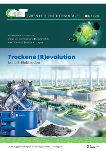
GET – GREEN EFFICIENT TECHNOLOGIES – English Language
- Text
- Harnischcom
- Materials
- Valve
- Electricity
- Grid
- Valves
- Technologies
- Efficient
- Pumps
- Hydrogen
- Efficiency
From the research
From the research Hydrogen Hydrogen-island grid of Ansbach University of Applied Sciences Smoothing volatile power generation and delivering green power in a predictable way Daniel Schultheiß, Dipl.-Ing. (FH) Dieter Jarosch, Prof. Dr.-Ing. Jörg Kapischke The greatest challenge for the energy supply of the future lies in the storage of large amounts of sustainably generated electricity. Although the expansion of renewable energy sources is still far from supplying countries like Germany in a carbon neutral way, photovoltaic and wind energy plants are already shutting down due to temporary overproduction. Electricity from private rooftop solar systems can easily be buffered in battery storage. For solar and wind farms on a megawatt scale, however, storage in batteries is not a practical solution. Ansbach University of Applied Sciences has implemented an innovative approach that temporarily stores photovoltaic electricity in the form of hydrogen gas. This allows large amounts of electricity to be retained almost loss-free, even over long periods of time. The system is designed as a self-sufficient island grid and can be coupled with the public power grid if required. Description of the island grid system The photovoltaic system of Ansbach University of Applied Sciences supplies laboratories with electricity, generates hydrogen and optionally feeds into the public grid. Due to the easy scalability of the system, the laboratories can be considered representative of the energy balance of a building, a commercial area, a company or a district. The building integration of the photovoltaic system (1) with its inverters (2) is shown in the upper part of Fig. 1. The special feature of the carbon dioxide-neutral system is the combined storage system, consisting of battery (4), fuel cell (5), electrolyzer (6) and hydrogen storage (7). If the labs need more electricity than the photovoltaic system can supply, the battery storage is discharged and at the same time the saved hydrogen is converted back into electricity with the fuel cell. If this is still not enough, additional electricity is received from the public grid. If the photovoltaic system produces more electrici ty than currently demanded in the labo ratories, the battery storage unit is charged and the electrolyzer produces hydrogen. If more electricity is available than consumers, battery storage and electrolyzer can absorb, the surplus is supplied to the public grid. The combination of battery storage and hydrogen brings together the advantages of both systems and eliminates their disadvantages. Battery storage systems can take in and release large amounts of electricity, but they only can do this for short periods of time. Electrolyzer, fuel cell and hydrogen storage can store and provide electricity over long periods of time and in large quantities. But they are not designed to handle peaks in generation and consumption. The vision being pursued with the demonstration plant is a system of many such self-sufficient plants that are nevertheless networked with each other and can Load < 2 kW Grid-tie inverter 3 x 3,8 kWp (for grid supply) H2 compressor 1 kW H2 electrolyzer 4 kW max. H2 Hydrogen storage 2 x 50 l, 200 bar; 1 x 87 l 14 bar ~ AC Off-grid inverter (Bidirectional battery inverter) Fuel cell 1 kW = DC Fig. 1: Schema photovoltaic hydrogen island grid system Battery capacity 48 V, 280 Ah System components at a glance: (1) Photovoltaic system with inverter for supplying power to the grid (2): 38.7 kW Switching station to island grid operation (3) Off-grid inverter: 4.2 kW (4) Battery storage: 8 kWh (5) Proton-exchange membrane fuel cell: 1 kW (6) Proton-exchange membrane electrolyzer: 4 kW, 13.8 bar (7) Compressed gas storage station: 87 l, 13.8 bar; compressed gas storage: 50 l, 200 bar; Hydrogen compressor: 200 bar 14 GREEN EFFICIENT TECHNOLOGIES 2022
From the research Hydrogen operate as a cluster when needed. If the energy sources of the individual cells differ (i. e. wind, solar, biogas), the systems can support each other in energy storage and supply. In addition to consumption and yield profiles, the demonstration plant will be used to investigate performance parameters, reliability, failsafe operation, durability and economic efficiency. Description of overall system The photovoltaic hydrogen island grid system can be operated in two modes, grid-connected and offgrid. Grid-coupling with the public grid comes into consideration when several power generation cells are connected together in regional vicinity in order to support each other with electricity via the public grid. It is conceivable, for example, that a photovoltaic power generation cell supplies a wind power generation cell with electricity when there is a high volume of solar power and a breather in the wind. A power supply system that is both green and stable is thus possible. The photovoltaic hydrogen island grid system at Ansbach University of Applied Sciences is being investigated primarily off-grid, i. e. in the island grid mode of operation. This enables practical tests of energy supply scenarios to be inspected in a well-defined system boundary at different times of the year and the day over longer periods of time. Description of system components and tasks An off-grid system with alternating current supply, which can be connected to the public grid if desired, consists of different system components with different performance data. Basic components are the energy generators, the inverters, the grid former, the power grid and, if applicable, energy storages. The special components of the presented system must fulfil defined tasks. The photovoltaic system either supplies the electricity to the public grid via current-controlled inverters (see Fig. 1: (1) and (2)) or the intercon- Fig. 2: Solar modules on the roof of the university building nected solar modules supply the electricity for an alternating current grid, grid, for example those of the pub- the AC voltage pulses of an external which is set up via a grid former. System components and functions are voltage and frequency. The invertlic grid, to produce a grid-identical described below. ers are equipped with a control system that changes the power depending on the measured grid frequency. Photovoltaic system and solar modules This means for example that, as soon as an increase of grid frequency is The photovoltaic system at Ansbach detected and a certain limit value is University of Applied Sciences consists of a total of 180 solar mod- electrical power. If the grid frequency exceeded, the inverters supply less ules with a total area of 296 m² and drops, an increasing power output a nominal power of 38.7 kW (see from the inverter takes place. Fig. 1: (1)). These modules are interconnected in strings of ten each. The power from the solar modules always In order to achieve the maximum orientation of the system is towards despite varying irradiation, a maximum power point tracker is integra- south with a 25° inclination. The IBC 215P polycrystalline solar modules ted. The maximum power point tracking changes the internal resistance have a surface area of 1.64 m² each and a nominal power of 215 W at a of the inverter minimally in certain nominal voltage of 28.7 V. time periods, whereby voltage and current change simultaneously and Inverter for grid supply thus the power of the photovoltaic Two of the strings, each equipped with ten solar modules, lead to an inverter (see Fig. 1: (2)). The inverter has the task of converting the direct current (DC) of the solar modules into a 230 V alternating current (AC) that can be used by all standard technical 230 V devices. A total of nine SB 3800 inverters convert the DC voltage of two parallel-connected strings into the grid-synchronous AC voltage and either feed this AC current into the public grid or make it available to the island grid. The inverters operate grid-connected and require Fig. 3: Photovoltaic-inverter for grid supply GREEN EFFICIENT TECHNOLOGIES 2022 15
- Seite 1 und 2: GREEN EFFICIENT TECHNOLOGIES 2022 H
- Seite 3 und 4: Editorial Hydrogen in the atmospher
- Seite 5 und 6: HAMPRO® HIGH-PRESSURE PROCESS TECH
- Seite 7 und 8: HOW EFFICIENT IS YOUR HYDROGEN COMP
- Seite 9 und 10: Leading article combustible waste (
- Seite 11 und 12: NEW: THE ELECTRIC STEAM GENERATOR [
- Seite 13: Cover story Fig. 3: In the course o
- Seite 17 und 18: From the research Hydrogen Hydrogen
- Seite 19 und 20: Pumps and systems Seawater desalina
- Seite 21 und 22: Driving the world Intelligent power
- Seite 23 und 24: Compressors and systems Hydrogen -
- Seite 25 und 26: Compressors and systems Biomethane
- Seite 27 und 28: Compressors and systems Biomethane
- Seite 29 und 30: Components Hydrogen energy from ful
- Seite 31 und 32: FILTECH Fig. 4: A total of eight en
- Seite 33 und 34: Components Elastomer seals and biol
- Seite 35 und 36: lit modular casing UMPE less steel,
- Seite 37 und 38: Components Radar sensor Fig. 3: The
- Seite 39 und 40: Components 3-phase decanter Fig. 2:
- Seite 41 und 42: Components Sustainable concrete the
- Seite 43 und 44: Trade fairs and events VALVE WORLD
- Seite 45 und 46: Trade fairs and events FILTECH 2023
- Seite 47 und 48: Companies - Innovations - Products
- Seite 49 und 50: Companies - Innovations - Products
- Seite 51 und 52: Companies - Innovations - Products
- Seite 53 und 54: Companies - Innovations - Products
- Seite 55 und 56: Brand name register NETZSCH Pumpen
- Seite 57 und 58: Come and see for yourself: www.harn
Unangemessen
Laden...
Magazin per E-Mail verschicken
Laden...
Einbetten
Laden...


