WA 101/WA 200/WA 200WB AUTOMATIC SPRAY ... - Anest Iwata
WA 101/WA 200/WA 200WB AUTOMATIC SPRAY ... - Anest Iwata
WA 101/WA 200/WA 200WB AUTOMATIC SPRAY ... - Anest Iwata

You also want an ePaper? Increase the reach of your titles
YUMPU automatically turns print PDFs into web optimized ePapers that Google loves.
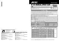
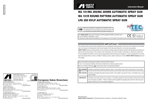
1. Fit the gun to fitting stay, aim at spraying direction and fix it.2. Connect atomizing air hose to atomizing air side (Cap marked side) and operating air hose to operating air side (CYL marked side).3. Connect fluid hose to fluid inlet side.4. Supply thinner to automatic gun. Spray and clean fluid passage with thinner.5. Supply paint to automatic gun and test spray and adjust air volume, fluid output and pattern width as necessary.Connecting example of air hose and fluid hose:MAINTENANCE AND INSPECTION<strong>WA</strong>RNING- First release air and fluid pressure fully according to item No. 3 of “Improper use of equipment” of <strong>WA</strong>RNING onpage 3.- Tip of fluid needle set has a sharp point. Do not touch the tip of needle valve during maintenance for protection ofthe human body.- Be careful not to damage the tip of the fluid nozzle or put your hand on it.- Only an experienced person who is fully conversant with the equipment can do maintenance and inspection.CAUTION- Never use commercial or other parts instead of ANEST I<strong>WA</strong>TA original spare parts.- Never immerse the whole gun into liquid such as thinner.- Never soak air cap set in solvent for extended period even if cleaning. It may cause defective pattern.- Never damage holes of air cap, fluid nozzle or fluid needle.Step-by-step procedureImportant4HOW TO INSTALL UNIONS FOR ATOMIZING AIR AND OPERATING AIR.1. Remove air nipple for atomizing and operating from gun body.2. Replace air nipple for atomizing (CAP marked side) and also replace air nipple for operating (CYL marked side) with half unionfor ø 8 mm air tube attached.3. Be sure to connect half unions to the gun body tightly.NOTE: Using air hose 12m (39.4ft) long, the inner diameter must be a minimum 8mm (0.315), so the gun can have the correct air volumeto atomize at 0.7 bar (10PSI) inside air cap.HOW TO OPERATEDimension DiagramMODEL A B C D E F<strong>WA</strong> <strong>101</strong> 27 44.5 85.5 147 36 86<strong>WA</strong> <strong>101</strong>R 27 37.5 79 140.5 35 85<strong>WA</strong> <strong>200</strong> 30.5 47.5 89 148.5 36 86<strong>WA</strong> <strong>200</strong>WB 30.5 47.5 89 148.5 36 86LPA <strong>200</strong> 30.5 47.5 89 148.5 36 861. Adjust operating air pressure from 3 to 4 bar (43 to 57 PSI).NOTE: Valve orifice inside three- way solenoid valve should be minimum ø 4 mm<strong>SPRAY</strong>(0.157 in) and also operating air hose length should be within 10m (32.8ft) with DISTANCEthe inner diameter more than ø 6 mm (0.236 in) to avoid delayed operation andany kind of failure.2. Although atomizing air pressure varies according to spray conditions, pull thepiston of the gun with the pattern adj. set fully opened and adjust as specified inabove specifications table.Only in the case of the LPA <strong>200</strong> H.V.L.P gun, it will atomize within 0.7 bar (10 PSI)inside air cap.3. Recommended paint viscosity differs according to paint property and painting conditions.15 to 23 sec/Ford cup#4 is recommendable.4. Set the spray distance from the gun to the work piece as near as possible within the range of 150_<strong>200</strong> mm (5.9 to 7.9 in) with <strong>WA</strong> <strong>101</strong>/<strong>101</strong>R,<strong>200</strong>_250 mm (7.9 to 9.8 in) with <strong>WA</strong> <strong>200</strong>/<strong>WA</strong> <strong>200</strong>WB, and 100_<strong>200</strong> mm (3.9 to 7.9 in) with LPA <strong>200</strong>. As LPA <strong>200</strong> H.V.L.P. gun is operated at lowair pressure, high transfer efficiency will not be obtained if the spray distance is too far.1. Clean fluid passages and air cap set. Spray a small amount of thinner to clean 1. Incomplete cleaning can fail pattern shape and uniform particles.fluid passages.Especially clean fully and promptly after use with two-component paint.2. Clean each section with brush soaked with thinner and wipe out with waste cloth. 2. Soaking whole spray gun in solvent may cause spray gun malfunction.When cleaning, never scratch any holes of air cap set and fluid nozzle, andfluid needle set.3. Before disassembly, fully clean fluid passages. 3. During disassembly, do not scratch seat section.(1) Disassemble fluid nozzle. (1) Remove fluid nozzle after removing fluid needle set or while keepingUse ring spanner, box wrench or optional exclusive spanner to disassemblefluid needle pulled, in order to protect seat section.fluid nozzle.(2)Disassemble fluid needle set.(2) Pull fluid needle set after loosening fluid needle packing set to protectRemove fluid adj. set and pull out fluid needle set from gun body.fluid needle packing set.Pay attention so that spring does not suddenly fly out since fluid adj. set isstrongly pushed by fluid needle spring and piston spring.(3)Disassemble piston set(3)Be careful not to damage piston packing when pulling out piston set.Screw rear section of fluid needle set into piston and pull out piston set.4.When you want to adjust fluid needle packing set, first tighten it by hand whilefluid needle set remains inserted. Then tighten it further about 1/6 turn (60-degrees)by spanner. When you remove needle packing set, do not leave plastic piece ofneedle packing set in the gun body.plastic piece(white)4. If you tighten fluid needle packing set too much, fluid needle set will notmove smoothly, resulting in paint leakage from tip of fluid nozzle. Try toadjust it carefully while pulling trigger and confirming movement of fluidneedle set. When you tighten it too much, first loosen it and then tighten itagain carefully.5. Turn pattern adj. knob counterclockwise to fully open. And then tighten pattern 5. If fluid adj. set is not fully opened, tip of it can contact and damage tip ofadj. guide into gun body.gun body set and cause seizure of thread.6. Apply Vaseline or oil to thread section of fluid adj. set and insert it into 6. If fluid adj. set is not fully opened, tip seat section of it can contact andgun body set while keeping it fully opened.Where to inspectdamage fluid nozzle and cause seizure of thread.Parts replacement standard1. Each hole passage of air cap and fluid nozzle Replace if it is crushed or deformed.2. Packing and O ring Replace if it is deformed or worn out.3. Leakage from seat section between fluid nozzle and fluid needle set Replace them if leakage does not stop after fully cleaning fluid nozzle andfluid needle set. If you replace fluid nozzle or fluid needle set only,fully match them and confirm that there is no leakage.5