SP-82/83/84/85/86 - Azel Technologies Inc
SP-82/83/84/85/86 - Azel Technologies Inc
SP-82/83/84/85/86 - Azel Technologies Inc
- No tags were found...

You also want an ePaper? Increase the reach of your titles
YUMPU automatically turns print PDFs into web optimized ePapers that Google loves.
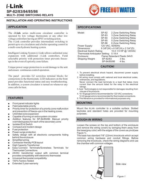
<strong>SP</strong>-<strong>82</strong>/<strong>83</strong>/<strong>84</strong>/<strong>85</strong>/<strong>86</strong>MULTI- ZONE SWITCHING RELAYSINSTALLATION AND OPERATING INSTRUCTIONSAZELTECHNOLOGIESAPPLICATIONThe i-Link series multi-zone circulator controller isoperated by low voltage thermostats or any other lowvoltage controllers having an <strong>SP</strong>ST switching action.The i-Link controller provides intermediate switching topermit up to six circulators and a boiler operating control ina multi-zone hydronic heating system.Intelligent Linking System ( i-Link) allows unlimited zoneexpansion with additional i-Link controllers. Fieldselectable priority with protection timer prevents freezeupsin the event of a priority zone failure.Unique power surge protection to avoid damage to the unitand ensure continuous control operation.The panel provides EZ screwless terminal blocks forconnections to the thermostats. LED indicators on the frontpanel provides functional status and easy troubleshooting.In addition, a system circulator is turned on whenever anyzone calls for heat.FEATURESFront panel indicator lightsField selectable priorityPriority timer for protection of a priority zone malfunctionand prevention of freeze-ups in the heating zones.Unlimited zone expansionCapable of turning on extra system circulatorAddition features for <strong>SP</strong>-<strong>84</strong>/<strong>85</strong>/<strong>86</strong>: Manual priorityoverride(bypass) for each of the secondary zoneIsolated End SwitchCompact and modern designFuse protectionPower surge protectionSafety design with all electronic components hidingbehind the enclosureSimplified wiringContractor friendly PCB layoutHigh Capacity TransformerEasy-Connect Terminals/Screwless Terminals forThermostat Connections24VAC transformer output with common terminalprovides compatibility with electronic thermostatUniversal thermostat compatibility100% Factory TestedExtended 3 year warranty<strong>SP</strong>ECIFICATIONSModel: <strong>SP</strong>-<strong>82</strong> 2 Zone Switching Relay<strong>SP</strong>-<strong>83</strong> 3 Zone Switching Relay<strong>SP</strong>-<strong>84</strong> 4 Zone Switching Relay<strong>SP</strong>-<strong>85</strong> 5 Zone Switching Relay<strong>SP</strong>-<strong>86</strong> 6 Zone Switching RelayPower Supply: 120 VAC, 50/60HzDimensions: 6 3/8”(W) x 6 5/8”(H) x 2 3/4”(D)Electrical Switch Rating: 10 A 1/3 HP @ 120VACThermostat Anticipator Setting: 0.18 AEnclosure: Flame Retardant Plastic 94V0Shipping Weight: <strong>SP</strong>-<strong>82</strong>/<strong>83</strong> 3 lbs.<strong>SP</strong>-<strong>84</strong>/<strong>85</strong>/<strong>86</strong> 4 lbs.MOUNTINGMount the i-Link controller to a suitable surface. Slottedkeyholes and standard holes are provided for mountingpurposes.ROUGH-IN WIRINGCAUTION!1. To prevent electrical shock hazard, disconnect power supplybefore installing.2. All wiring must comply with national and local electrical codes,ordinances, and regulations.Never connect the load terminals to a load that takes morecurrent than the amount listed for the relay in the electricalratings.3. <strong>Azel</strong> <strong>Technologies</strong> is not responsible for damages resulting frommisuse of its products.4. 10-18 gauge wire is recommended for 120 VAC conections;12-22 gauge wire is recommended for thermostat connections.5. This literature is provided for informational purposes only.Loosen the screws on the top and bottom of the enclosureand remove the wiring covers by swinging them away fromthe base(grey color) with the edges of the covers as pivot(seeFigure 1).The base has standard 7/8” (22mm) knockouts which acceptcommon wiring hardware and conduit fittings. Beforeremoving the knockouts, check the wiring diagrams and usethe chamber with common voltages.Side viewFigure 1