SRCC OG-300 Certified Solar Water Heating System - Free Hot Water
SRCC OG-300 Certified Solar Water Heating System - Free Hot Water
SRCC OG-300 Certified Solar Water Heating System - Free Hot Water

You also want an ePaper? Increase the reach of your titles
YUMPU automatically turns print PDFs into web optimized ePapers that Google loves.
_______________________________________________________________________________<strong>SRCC</strong> <strong>OG</strong>-<strong>300</strong> <strong>Certified</strong> <strong>Solar</strong> <strong>Water</strong> <strong>Heating</strong> <strong>System</strong><strong>Free</strong> <strong>Hot</strong> <strong>Water</strong> Collector 5000 Series – <strong>Free</strong>dom 5002, 50032011044A - Liberty - 4002 XG2011044B - Liberty - 4003 XG2011047A - Liberty - 4002 XE2011047B - Liberty - 4003 XEType: AC Circulating Pump and Differential ControlInstallation, Operation and Maintenance ManualThe solar energy system described by this manual, when properly installed and maintained, meets the minimumstandards established by the <strong>SRCC</strong>. This certification does not imply endorsement or warranty of this product by<strong>SRCC</strong>.Version 2011.02_______________________________________________________________________________<strong>Free</strong> <strong>Hot</strong> <strong>Water</strong> 2146 Bering Dr. San Jose, CA 95131 Tel: 408 218 3660 Fax 408 872 4142www.<strong>Free</strong><strong>Hot</strong><strong>Water</strong>.com
Table of ContentsSafety Information ................................................................................................................................................... 3Transport Note .................................................................................................................................................. 4Installation, Operation And Maintenance Manual .................................................................................................. 5Introduction ....................................................................................................................................................... 5<strong>System</strong> Description ........................................................................................................................................... 6Specifications .................................................................................................................................................... 6<strong>Free</strong>ze Protection .............................................................................................................................................. 7Tools Needed .................................................................................................................................................... 8Collector Specifications ........................................................................................................................................... 9Collector Certification <strong>OG</strong>100 ......................................................................................................................... 10Pressure drop and flow rates .......................................................................................................................... 11General Closed Loop <strong>System</strong> Schematics ....................................................................................................... 12Precautions ..................................................................................................................................................... 14Collector Orientation ...................................................................................................................................... 16Installation Steps for Roof Mounting .................................................................................................................... 17Pitched Roof Mounting ................................................................................................................................... 17Recommend Anchor Points ............................................................................................................................ 20Flat Roof Installation Instructions ................................................................................................................... 22Installing the <strong>Solar</strong> Tank ........................................................................................................................................ 24Basic plumbing connection diagram ............................................................................................................... 26Commissioning ................................................................................................................................................ 27Regular Care .................................................................................................................................................... 28Anode Replacement ........................................................................................................................................ 29Pump Station and Controller ................................................................................................................................. 34Mounting ........................................................................................................................................................ 35Options ............................................................................................................................................................ 36Installing the Expansion Tank ................................................................................................................................ 38<strong>Solar</strong> Thermal Controller ........................................................................................................................................ 39<strong>System</strong> Pressure Guide ......................................................................................................................................... 45Charging the <strong>System</strong> ....................................................................................................................................... 46Propylene Glycol Material Safety Data Sheet .................................................................................................. 48Labels .................................................................................................................................................................... 50<strong>System</strong>s Parts List ................................................................................................................................................. 52Trouble Shooting .................................................................................................................................................. 53Vacation Planning ........................................................................................................................................... 56Maintenance Notes ........................................................................................................................................ 57Installer Information ............................................................................................................................................. 58Warranty & Guaranty ............................................................................................................................................ 58Collector Warranty Certificate ............................................................................................................... 59• Page 2
• Page 3
• Page 4Attention: Do not lift the collectors by the connections and or the screw threads
DOMESTIC SOLAR WATER HEATER SYSTEMINSTALLATION, OPERATION AND MAINTENANCE MANUALThe <strong>Free</strong> <strong>Hot</strong> <strong>Water</strong> domestic solar water heating system has gone through an extensive design, technical andperformance review by the <strong>Solar</strong> Rating & Certification Corporation (<strong>SRCC</strong>). The installation of your <strong>Free</strong> <strong>Hot</strong> <strong>Water</strong>system is intended to be executed by properly licensed and experienced professional contractors in accordance with<strong>SRCC</strong> Standard <strong>OG</strong>-<strong>300</strong>, "Operating Guidelines and Minimum Standards For Certifying", and must conform toapplicable federal, state and local regulations, codes, ordinances and standards governing the installation of solarwater heating systems.The solar energy system described by this manual, when properly installed and maintained, meets the minimumstandards established by the <strong>SRCC</strong>. This certification does not imply endorsement or warranty of this product by the<strong>SRCC</strong>. <strong>OG</strong>-<strong>300</strong> system certification is granted to <strong>Free</strong> <strong>Hot</strong> <strong>Water</strong> by the <strong>SRCC</strong>. It may not be used for any commercialpurpose without the prior written consent of <strong>Free</strong> <strong>Hot</strong> <strong>Water</strong>. <strong>Free</strong> <strong>Hot</strong> <strong>Water</strong> must approve any deviation from thematerials and methods described in this manual in writing.CONGRATULATIONS!Congratulations on investing in one of the most advanced solar water heating systems available. Utilizing the free,environmentally friendly energy from the sun to heat water for your home makes so much sense. <strong>Solar</strong> energy isefficient, safe and reliable and your decision to use solar energy is helping to preserve our environment and toreduce our rapid depletion of non renewable, fossil fuels.The FREE HOT WATER solar water heating system uses the sun’s energy as a source of heat to produce hot water fordomestic household use. Designed to meet the certification requirements of <strong>SRCC</strong> 0G-<strong>300</strong>, FREE HOT WATER solarwater heating systems are reliable, and can typically generate from 50% to 80% of your annual household waterheating needs from the sun. Your remaining hot water needs can be supplied by your existing electric or gas waterheater or boiler. Results will vary based upon on your specific region in the country. Your new <strong>Free</strong> <strong>Hot</strong> <strong>Water</strong><strong>System</strong> uses state-of-the-art technology and will provide you with many years of maintenance free and dependableservice. If you have any questions, please feel free to contact your local dealer or our home office.IntroductionThe system performance varies as a function of the household hot water load. The ambient air temperature, theroof pitch and orientation along with seasonal solar intensity will determine the amount of hot water generated byyour FREE HOT WATER solar water heating system.Your FREE HOT WATER solar water heating system uses a circulation pump that circulates a propylene glycol heattransfer fluid throughout the system. This fluid protects the collector piping from freezing, prevents corrosion ofsystem components, and keeps scale deposits from forming that could reduce the performance of the system.Proper maintenance of the propylene glycol in the system can protect the solar water heating system to minus 40°Fahrenheit. This manual is intended to familiarize you with the proper installation and maintenance of your FREEHOT WATER solar water heating system. This system must be installed by a licensed solar or plumbing contractor inaccordance with <strong>SRCC</strong> Standard <strong>OG</strong>-<strong>300</strong> and all applicable national, state and local codes. Failure to follow theprocedures described in this manual can void the manufacturers’ warranty.• Page 5
<strong>System</strong> DescriptionThe FREE HOT WATER solar water heating system is a closed-loop active solar system which, when installed with asuitable auxiliary heat source, can act as the primary source of domestic hot water for residential use. The systemcomponents provided with the FREE HOT WATER solar water heating system include the solar collectors, collectorflashings, solar loop pipe and fittings, solar storage tank, solar pump station and controller, temperature sensors,expansion tank, air separator, mixing valve, and non-toxic propylene glycol heat transfer fluid. The solar collector isthe engine of the FREE HOT WATER solar water heating system.When the sun is shining, the heat energy is absorbed by the solar collector and transferred to the heat transfer fluidcirculating through the solar collectors. The system pump efficiently circulates this heated fluid through thecollector’s piping and the heat exchanger located in the solar storage tank. As the heat transfer fluid passes throughthe heat exchanger, the heat in the fluid is transferred by conduction to the potable water in your solar storage tankcausing the temperature in the tank to rise. This process continues as long as the sun is shining or until thetemperature in the solar storage tanks reaches its maximum temperature set point.General InstructionsInstallation must only be carried out by qualified personnel. The entire information in these instructions is intendedexclusively for such qualified personnel. Only the supplied material should be used for the installation. Prior to startinginstallation and operation of the solar collector system, please inform yourself about the applicable local standards andregulations. The use of a carrying strap is recommended for transporting the collector. The collector must not be liftedat the connections or on the threading. Avoid impacts and mechanical influences on the collector, in particular on thesolar glass, the rear panel and pipe connections.The collectors may only be mounted on sufficiently load-bearing roof surfaces and substructures. It is imperative thatthe static load bearing capacity of the roof or substructure is checked in terms of local and regional conditions prior toinstallation of the collectors by the customer, if necessary through the involvement of a structural engineer.Particular attention should be paid to the quality of the (timber) substructure in terms of the stability of the screwconnections necessary for fastening the collectors.SpecificationsThe FREE HOT WATER solar water heating system is designed to produce domestic hot water from either solarcollector, an electrical or gas backup, or a boiler back up (provided by others). The FREE HOT WATER systems canalso be used as a solar preheat system to conventional electric or gas water heaters (provided by others).Collectors and flashingsFREE HOT WATER solar collectors and flashings allow for a low profile, roof integrated, solar panel installation. TheFREE HOT WATER collector is made up of copper tubes and a plate that is covered with a highly selective absorbercoating; this assembly is enclosed in a well insulated aluminum frame or “box” and covered with low-iron temperedglass glazing. FREE HOT WATER solar water heating systems are available for integration onto either shingle or tileroofs. The collector is suitable for angles between 15° (minimum) and 75° (maximum). The collector connectionsand the ventilation openings must be protected against the penetration of water as well as against contaminationthrough dust etc.• Page 6
<strong>Solar</strong> Storage TankAll FREE HOT WATER solar water heating systems will include a solar storage tank with the solar heat exchangerlocated in the bottom section of the tank to heat the entire water volume of the tank. The tank contains athermometer located on the outside of the tank so you will know the temperature in the tank.Collector Loop PipingFREE HOT WATER solar water heating systems are designed for use with copper pipe or pre-insulated corrugatedstainless steel flexible piping. No other piping may be substituted for use in the solar loop. Collector pipinginstallation requires the use of copper and brass fittings in the collector loop. Piping in new solar installations mayhave dirt, grease, or other impurities that over time affect the quality of the propylene glycol heat transfer fluid. Athorough cleaning is required before charging the system with glycol. All vertical piping between the storage tankand the collector shall be supported at each story or at maximum intervals of ten feet (10’) using pipe hangers. Ifadditional supports are needed, copper plumbers tape or tube strap may be used. The pipe insulation may not becompressed or crimped by the strapping material.The installation of all horizontal and vertical piping may not reduce the performance or rating of any structuralmember or fire rated assembly. Adhere to all applicable local codes and ordinances.The collector loop cold supply and hot return lines must be well insulated with the high quality flexible closed cellinsulation to minimize heat loss. There shall be no exposed piping or fittings. The wall thickness of the pipeinsulation should not be less than ¾”. Any above ground exterior pipe insulation that may be subject to UVdegradation must be wrapped with foil tape or painted with two coats of high quality water-based acrylic resincoating.Pump Station ControllerAll FREE HOT WATER solar water heating systems include a pump station controller that include the temperatureand pressure gauges, pressure relief valve, check valves, ball valves, fill and drain valves, and differential controllerrequired to properly operate the FREE HOT WATER solar water heating system. The system temperatures for thecollector and storage tank can be read from the differential controller. Typical tank operating temperatures canrange from the cold supply of 40°-80° F up to 180° F which represents the high limit of the tank. This will varydepending on the climate where the system is installed. The collector temperature sensor should be 5°-20° F abovethe tank sensor during normal operation. During idle periods, when there is no sun, the collector will read theambient temperature and when there is full sun upward to 250° F.Balance of <strong>System</strong>sThe balance of components in all FREE HOT WATER solar water heating systems: solar loop pipe and fittings,temperature sensors, expansion tank, air separator, mixing valve, and non-toxic propylene glycol heat transfer fluidcomponents carry temperature and pressure ratings required of the FREE HOT WATER solar water heating systemdesign.<strong>Free</strong>ze ProtectionThe FREE HOT WATER solar water heating system can be operated down to ambient temperatures of –40°F usingproper concentrations of propylene glycol. <strong>Free</strong>ze tolerance limits are based upon an assumed set of environmentalconditions. Refer to the propylene glycol specification sheet under the “Flushing and filling” section of this manualfor recommended concentration of propylene glycol and distilled water to provide adequate freeze protection inyour specific climate. The differential controller uses temperature sensors to monitor the temperature differencebetween the collector and the solar storage tank. The controller turns on when the collector is 20° F above tank• Page 7
• Page 10
• Page 12
• Page 13
PrecautionsFor safety reasons you should only fill the collectors when there is no direct irradiation from the sun (covering thecollectors can be an option). Especially in regions exposed to frost, for flat plate collectors you should use a mixtureof anti freeze with water (40% anti freeze). The solar thermal system should be filled and commissioned within oneweek of installation, because heat build-up in the collector array can damage the flat gaskets in empty systems. Ifthis is not possible, the flat gaskets should be replaced before commissioning to prevent leakage.Attention : Anti freeze that is not premixed must be mixed with water prior to charging the systemRecommended antifreeze for flat plate collectors – FHWM-GY-5000525% antifreeze / 75% water mix - freeze point 14°F40% antifreeze / 60% water mix - freeze point -5°F50% antifreeze / 50% water mix - freeze point -25°FIt may not be possible to completely empty collectors one they have been filled. For this reason collectors exposedto frost should only be filled with a distilled water/antifreeze mixture, also for pressure and function tests.Alternatively, the pressure test can also be carried out using compressed air and leak detection spray.Installing the temperature sensorThe temperature sensor should be installed in the sensor sleeve nearest to the collector array flow. To ensureoptimal contact between the sensor and the surrounding environment, the gap between the sensor sleeve and thesensor element should be filled with a suitable conducting compound. All materials used for installing temperaturesensors (sensor element, conducting compound, cables, sealing and insulating materials) must be suitablytemperature resistant (up to 482° F).Operating pressure: The maximum operating pressure is 145 psi.BleedingThe system must be bled:- When commissioning the system (after filling the collectors)- 4 weeks after commissioning- When necessary, e.g. if there are malfunctionsWarning: Risk of scalding due to steam and hot heat transfer fluid!• Page 14
Only operate the bleeding valve if the temperature of the heat transfer fluid is < 140° F.When bleeding the system, the collectors must not be hot! Cover the collectors and, if possible, bleed the system inthe morning.See Material Safety Data Sheet on page 45 for safety information.Check heat transfer fluidThe heat transfer fluid must be checked every two years with regard to its antifreeze and pH value.- Check antifreeze using antifreeze tester and replace or refill if necessary!Target value is ca. - 77° F and - 22° F depending on climatic conditions.- Check pH value with a pH indicator rod (target value approx. pH 7.5):If the limit pH value is less than ≤ pH 7, replace the heat transfer fluid.Maintenance of the collectorThe collector or the collector array must be inspected visually, once a year, for any damage, leaks andcontamination. Additional recommendations on operation and maintenance can be found in the supplier's generaldocumentation and instructions on commissioning and maintenance.Connecting the collectors to one anotherThe collectors must be connected to one another and/or to the connection pipes using the supplied connectors.When tightening the union nuts and/or compression fittings, always balance (counter) the torque* with a pipe wrenchor another spanner to prevent damage to the absorber.Do not run the solar collector(s) without a Pressure Relief Valve, safety valve in the system to avoid over pressure inthe solar circuit.Warning: <strong>Free</strong>ze tolerance limits are based upon an assumed set of environmental conditions.Warning: If the freezing point of the fluid in an exposed part of the system is above the freeze tolerancelimit specified for the system: Extended period of cold weather, including ambient air temperaturesabove the specified limit, may cause freezing in exposed parts of the system. It is the owner’sresponsibility to protect the system in accordance with the Supplier’s instructions if the air temperature isanticipated to approach the specified freeze tolerance limit.• Page 15
<strong>Solar</strong> Collector OrientationOperating your <strong>Free</strong> <strong>Hot</strong> <strong>Water</strong> solar water heater for optimal efficiency is based on the correct orientation, pitch,and location of the solar collectors. In North America, collectors should be oriented due south, however may beoriented up to 45 degrees east or west of due south with minimal losses in solar gain. Optimal pitch is +/– 10° fromthe latitude of the installation site.<strong>Free</strong> <strong>Hot</strong> <strong>Water</strong> solar collectors must be installed at a minimum pitch of 15 degrees from horizontal, and for optimalperformance, the recommended pitch is between 15–60 degrees. The collector should be mounted as close to thestorage tank as possible to minimize heat loss in the piping runs. The solar collector must be located in an area ofthe roof that will be un-shaded for the majority of the day (from 9:00–3:00) all year round. Adjacent buildings andtrees should be checked for possible winter shading.The following diagram below is an example of how the collectors can be connected to one another. However, theactual connection may be different depending on structural conditions. A maximum of 6 collectors may beconnected in a series! If a collector panel is made up of more than 6 collectors, the panel must be connected severaltimes in parallel• Page 16
Installation Steps for Pitched Roof Mounting1. Locate and mark the roof rafters into which the solar collector mounting brackets will be mounted(one way to find rafters is to see the “tails” at the edge of the roof).2. To create a set point for plumbing and level installation, measure the distance from the edge of theroof to the desired mounting points and mark the points where the collector mounting brackets will beinstalled (fig 1.2).*Note: you need to install a screw into one of the holes in the mounting bracket, not both holes (fig1.1).* Note: for collector model 7000 upper and lower mounting bracket should be 78” apart measuredfrom top of top bracket to bottom of bottom bracket.* Note: both the bottom and the top mounting brackets should be placed as per figure 2.0 from eachother as possible in the width dimension.Fig 1.1 Fig 1.23. Determine where penetration will be to connect the solar hot water collector with the storage tankand/or the water supply (use 2 pre-insulated ¾” steel flex hoses or 2 insulated ¾” copper pipes forthat connection).Note: *For a two-collector system that will be elevated above the roof surface, a good location for thispenetration is directly between the two collectors.4. Holes should be slightly overlapping to form a sideways “8” shape (see illustration 1.3). Mark thepenetration before making holes. If you are installing on a composition shingle roof make holes 5”below the bottom of the shingle above the penetration.• Page 17
Fig 1.35. Using a hole saw, cut the hole (penetration) for the 2 hoses or pipes from step 3.6. If using flex hose: before connecting the hose, measure, cut, and lay out the hose, including enoughlength for 8’ of hose above the roof. Pull the hose through the hole.7. Begin mounting bracket installation with bottom bracket. Mark a straight chalk line between the 2bottom bracket mounting points.Fig 1.48. For composition shingle roof, DO NOT PENETRATE THE COMPOSITION SHINGLE. Before installingscrews, lift the composition shingle at the install point and slide the mounting bracket in, beneath thetop composition shingle. Place the bracket so that the top surface composition shingle clears thebracket when folded (lifted) up or down and mark an outline of the mounting bracket where themounting bracket will be fastened to the roof rafter or other appropriate mounting substrate. Themarked area should be 1.5” wide and 2.5” high.9. Next, using a cutting tool, cut out a piece of the roof material beneath the top layer of the compositionshingle (the top layer will NOT be penetrated for the mounting brackets) as marked 1.5” X 2.5” in theshape of the mounting bracket.Cutting out a piece of roofing material will provide for a flush-mounted roofing bracket.• Page 18
Fig 1.5 Fig 1.6 Fig 1.710. Pre drill mounting bracket screw holes into rafter or other appropriate mounting substrate (one holeper bracket) using a 7/16” drill bit.11. FOR ONE BOTTOM BRACKET ONLY, apply <strong>Solar</strong>flex in bracket screw holes, on roof surface wherebracket will be placed, and on bracket surface that will be facing down. Fasten first bottom bracketonly to rafter or substrate using ½” screw.Note: *begin installing second bottom bracket only after confirming level installation.12. Follow Steps 8-11 for the second bottom bracket BUT DO NOT YET FASTEN THE SECOND BRACKETWITH SCREW.13. WITHOUT TIGHTENING IT COMPLETELY, place the bottom profile on the bottom brackets using theclamps and ½” bolts.14. Using a 4’ level, make sure the profile is level.15. Once the profile is level, remove it and fasten the second bottom bracket to the roof using ½” screw.Fig 1.816. Apply AT 302-60 (recommended, not supplied-FHW-AA 60050)to ½” bolts for clamps. Fasten Clamps tobrackets using ½” bolts and washers. Attach profile to clamps, tighten completely.17. Follow steps 1-16 for top mounting brackets.• Page 19
Fig 1.9018. Place collector on profiles, checking to make sure it fits and lines up appropriately.Recommend Anchor Points19. Once collector fits and lines up appropriately, apply AT 60 to ½” bolts for collector and fasten collectorto profiles using ½” bolts and washers.20. If installing more than one collector, cut flex hose or copper pipe in length necessary to connectcollectors. On all plumbing connections use Anti Leak (part # FHWM-AA-72050)• Page 20
21. Connect collectors with each other (if installing more than one collector) and with storage tank, usingflex hose or copper pipe and compression fittings.Note: * Tighten compression fittings gently by hand and then 1.25 turns with a wrench. Avoid overtighteningas this can damage the flex hose or copper tubing.22. Cap unused collector connections with cap.23. If not already labeled, install hot and cold water in and out labels to collector and storage tank.24. Test system, checking for any leaks and for performance. Collector mounting must be capable ofmaintaining tilt and azimuth.Fig 1.91• Page 21
Flat Roof Installation Instructions1. Locate and mark the roof rafters into which the solar collector mounting Frame will be mounted(one way to find rafters is to see the “tails” at the edge of the roof).2. To create a set point for plumbing and level installation, measure the distance from the edge ofthe roof to the desired mounting points and mark the points where the collector mounting frame(fig 2.2) will be installed (fig 2.1).Fig 2.2Fig 2.3Fig 2.11. Follow the plumbing connections (Blue for Supply and Red for return) Determine where penetrationwill be to connect the solar hot water collector with the storage tank and/or the water supply (use 2pre-insulated stainless steel flex hoses or 2 insulated copper pipes for that connection).2. Once the frame(s) are attached to the roof, install the profiles as per fig 2.33. Proceed installing the collectors using the M8 screws provided with the frame kit as per the illustratedin fig 2.4Fig 2.4• Page 22
4. If you have more than one bank of 3 collectors you will need to use the FHW expansion band asillustrated in fig 2.5Fig 2.55. At the end of every bank please connect to the main as described in fig 2.6Fig 2.6• Page 23
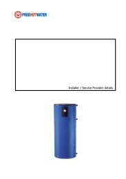
Installing the <strong>Solar</strong> TankIMPORTANT INFORMATION<strong>Free</strong> <strong>Hot</strong> <strong>Water</strong> <strong>Solar</strong> Storage Tank should be installed in accordance withthese installation instructions, Local plumbing regulations, municipal buildingcodes and any other relevant statutory regulations. Observation of theseinstructions and the associated component instructions is most important andfailure to do so could void the benefits of warranty. All work is to be carried outby a registered plumber, and to be in accordance with Local and NationalOccupational Safety Guidelines. The information contained in this manual, andall other information or advice provided by <strong>Free</strong> <strong>Hot</strong> <strong>Water</strong> Limited in connectionwith the purchase, installation use and service of the <strong>Free</strong> <strong>Hot</strong> SST, is given in goodfaith. <strong>Free</strong> <strong>Hot</strong> <strong>Water</strong> will not be liable for any person for any inaccuracy or omissionin the information arising through the fault of <strong>Free</strong> <strong>Hot</strong> <strong>Water</strong> directly or indirectly.A pressure-limiting valve of 70 PSI (500kPa) max rating must be fitted. Failure toinstall a pressure limiting valve where required will void the warranty.SAFETYScalding occurs at 120 F (500C). This appliance is capable of providing hot water above this temperature. Allinstallers must install an anti scalding valve and advise customers of the potential hazard of scalding in accordancewith the relevant National standards. Young children should not play with the appliance. A combinationtemperature Pressure Relief valve with a maximum rating of 120 Psi (850kPa) must be fitted. <strong>Water</strong> may drip fromthe discharge pipe of this valve. This pipe must be left open to the atmosphere. For more information, please referto the Regular Care section of this manual. These safety devices must not be tempered with or removed from theappliance under any circumstances. All components must remain accessible for maintenance and servicing.Secure all pipe according to regulation and do not over tighten hangers as to compress insulation.About Your <strong>Water</strong> Heater1. <strong>Free</strong> <strong>Hot</strong> <strong>Water</strong> SST is a high technology tank backed up by new manufacturing methods in order to offerquality of goods to consumers.2. The main goal of producing the <strong>Free</strong> <strong>Hot</strong> <strong>Water</strong> SST Tanks is heating and storing potable hot water in amain pressure storage tank using solar energy. Potable hot water is stored in the main water storage tankseparately from the heating liquids in the coils.• Page 24
3. The heating fluid, which is heated in the heat source, is circulated between the heat source and tank’s coil.The warmed fluid takes its heat from the heat source and transmits to the water heater.4. <strong>Free</strong> <strong>Hot</strong> <strong>Water</strong> tank inner surface is enameled. The meaning of enameled coating is as covering sheetiron’s inside surface with glass.5. <strong>Free</strong> <strong>Hot</strong> <strong>Water</strong> tanks are protected by a magnesium anode rod in order to prevent the damage of cathodecorrosion. The magnesium anode rod ought to be replaced every 36 months by a certified plumber, andcan be installed and uninstalled. The replacement steps of the magnesium anode rod must be followedaccording this manual.6. <strong>Free</strong> <strong>Hot</strong> <strong>Water</strong> exterior surface is covered by 2.5 lbs/cm³ (40 kg/m³) and 2” (50 mm) polyurethane (except800D and 1000D) in order to diminish the loss of the heat. The <strong>Free</strong> <strong>Hot</strong> <strong>Water</strong> 800D and 1000D1. insulation foam is removable. This convenience allows easy delivery and access through narrow doors fortank placement.7. The type of water heater to choose (single or double coil) depends on the heater and if you are planning toextract heat. For example, if the tank will be heated with a solar system, <strong>Free</strong> <strong>Hot</strong> <strong>Water</strong> single coil waterheater would be appropriate.8. <strong>Free</strong> <strong>Hot</strong> <strong>Water</strong> SST have been produced to suit a wide range of applications and installation shapes.2. In this manual we present the most common applications, however if you require advice on any otherapplication, please contact our service desk on 408-432-9900 or info@<strong>Free</strong>hotwater.comPlumbing ConnectionDelivering and mounting the <strong>Free</strong> <strong>Hot</strong> <strong>Water</strong> tank1. The product should be kept away from sharp tools during loading or delivering.2. The product’s inlet and outlet pipes should be protected against any damages during delivery.3. The product should not be left or placed where it’s exposed directly to weather such as direct sunlight, rainsnow etc.4. If possible leave headroom of one water heater length so the anode can be inspected or replaced.Remember you may have to remove the entire water heater later for servicing as per instructions in thismanual.5. Outdoor installations decrease the water heater performance and may increase the energy consumption.6. If the product is installed on the floor, the floor must be dry and moisture proof.7. Consider a drainage tray when required.8. Tank must be strapped and mounted in accordance to local plumbing regulations and seismic regulations.9. <strong>Free</strong> <strong>Hot</strong> <strong>Water</strong> Limited does not accept any responsibility, if the product is physically damaged or operatesinefficiently due to wrong mounting or inappropriate delivery.Basic Plumbing connection of the <strong>Water</strong> heater1. In order to use the water heaters to their highest efficiency, tanks must be connected according to thediagrams.2. The capacity of the water resource has to be chosen and adjusted in order to maintain the hot water supplydemand.3. Start with the Basic Diagram before conducting any specific application connection.4. Fit the cold inlet valves prior to commissioning the tank.5. Ensure that the TPR Valve is fitted and that the service circulation is blocked or connected prior tocommissioning the tank with water.6. Lag all hot water pipes coming out of the water heater.• Page 25
Plumbing Connection of additional applications1. Please follow the diagrams and the notes.2. If you are in doubt or attempting to install an application outside the below diagrams, please contact <strong>Free</strong><strong>Hot</strong> <strong>Water</strong> service desk for advice.IMPORTANT NOTE:When using copper pipes, use Teflon or FHWM-30572200 neutral adaptor between the brass fitting and the portthread to prevent electrolysisTank Sizes79 Gallon - FHW Single Coil <strong>Solar</strong> Tank 79 gal - FHWC-STEN-079-SC105 Gallon - FHW Single Coil <strong>Solar</strong> Tank 105 gal - FHWC-STEN-105-SCImportant Notes:Not all valves are supplied with the water heater. The above diagram describes valves for a mainspressure arrangement; however the tank could also be fitted to a low pressure system. <strong>Free</strong> <strong>Hot</strong> <strong>Water</strong>tanks are equipped with a service circulation port.<strong>Free</strong> <strong>Hot</strong> <strong>Water</strong> recommends ¾” Stainless Steel Helical Flexible Tube for connections on the roof (nowelding work needed and pre-UV R6 insulated), or use standard ¾” copper pipe. All outdoor pipe is tohave UV protected insulation. Final 5 feet of cold water piping is insulated to R-2.6• Page 26
Important Notes:1. The diagram shows generic drawings of connections to and from <strong>Free</strong> <strong>Hot</strong> <strong>Water</strong> tank. Follow the specificinstructions of the solar panel supplier for the actual detailed arrangement, components and valves.2. When using <strong>Free</strong> <strong>Hot</strong> <strong>Water</strong> tanks, solar collectors should be installed in bottom coil (boiler, wetback orheaters should be installed in upper coil.3. It is highly recommended running the solar system via the <strong>Free</strong> <strong>Hot</strong> <strong>Water</strong> coil on a close loop arrangement.Open loop solar is also possible using the Service Circulation port for the solar return instead of the Coil <strong>Hot</strong>port, and branching of the Cold Inlet instead of using the Coil Cold port.4. When connecting commercial solar system, ensure that the energy going through the solar coil is lowerthan the max kW rating of the coil as per instructions. Excess energy above the coils rating will void thewarranty.• Page 27Warning: Open loop solar carries a frost risk to the panels since antifreeze is not used. This <strong>OG</strong><strong>300</strong> systemmay not qualify for Federal and State rebates if Open Loop method is used.Commissioning the <strong>Solar</strong> TankVERY IMPORTANT: Prior to turning on any heating application such as solar, boiler or a heater, the tank MUST BEFILLED UP WITH WATER1. Make sure that all hot water taps are close off2. Open the inlet tap fully to fill up tank3. Open each hot water tap till water flows freely4. Check all pipes for leaks5. Switch on the elements and set the timer/controller (if one is installed)6. Attend to any other external heating applicationsDraining The <strong>Water</strong> Heater1. Turn off the power supply of the elements2. Turn off all external heating applications3. Turn off cold inlet supply at the 3 in 1 valve or at the meter4. Open a hot water tap to drain the plumbing5. Turn off the hot water tap6. Disconnect the hot water outlet union7. Open to atmosphere Cold <strong>Water</strong> Expansion Valve to let water flow via the8. drain pipe<strong>Water</strong> Quality<strong>Free</strong> <strong>Hot</strong> <strong>Water</strong> SST heater has been manufactured to deal with most qualities of US water supply. Desired waterquality levels: pH Level between 6.5 and 8.5Chlorides: up to 200 ppm, Total Dissolved Solids (TDS) up to 1000 mg/LSaturation Index between -0.8 and +0.8If your water quality or the heating liquids are outside the above range, youshould fit appropriate water filtration.
Caution:If water TDS is above 600 mg/L, there is a possibility of hydrogen gasaccumulating in the top of the water heater during long periods of no use.If the water heater has not been used for more than 2 weeks:1. Open the hot water tap and let water flow for 1 minute.2. Hydrogen gas is flammable; therefore make sure that there is no smoking, sparks or naked flames near thetap.3. Do not operate any hot water appliance such as a washing machine or a dishwasher prior to the aboveprocedure.Regular CareEvery Six Months: Near the top of the water heater you will find the TPR Valve (Temperature Pressure Relief Valve).Raise the lower lever and gently release some water into the relief pipe.Notes:1. If water does not flow down the relief pipe, or if water does not stop flowingonce you released the lever, contact your plumber.2. It is normal for the valve to release small amount of water during heating cycles.3. Never block the relief drain pipe.Every 3 years - maintenance: A qualified plumber should check and if needed replace the sacrificial anode of thewater heater.Every 5 years - maintenance: A qualified plumber should replace the TPR valve, of the water heater and shouldclean coils of the tank via the clearing door.Regular Care – Service PersonAnode Replacement <strong>Free</strong> <strong>Hot</strong> <strong>Water</strong> SST1. Disconnect the power supply to the waterheater1. Drain approximately 5 to 10 lt. from tank asper instructions.2. Unscrew service cap (11) gently3. Take out the soft foam insulation (10) anddisassemble anode ground cable fromflanges cap (7) and then from flanges (2).4. Disassemble the flanges (7) and thenremove the flanges gasket (4).7. Open the nut that is on the flanges (7) andattach it to the anode rod.8. Remove old anode rod (3) over flanges andkeep the anode insulation bush and anodegasket (5).9. Assemble new anode rod from the side ofenameled flanges (7); leave insulated bush• Page 28
(5) on the other side, and install nut overanode behind the beam gear side.10. Locate flange gasket through inlet of the tank.Replace gasket if needed11. Locate flange exactly central side of thetank flange. Fasten nuts in a crosstightening order as per page 18. Don’t leaveout nut flakes (6) – it needs to be directlyopposite flange number (1) as shown.12. Assemble stone wool, place the tail ofthermometer couple on the bush, which ison the flange. Locate the service cap on thebush of top cap.Sensor ConnectionsSensors sense the temperatures when the tank is connectedto heating applications, and transfer the reading to thecontrollers, such as 3 way valve, pumps and otherelectronic controllers. Sensor bushes are located in themost appropriate level for heat distribution in the tank.Sensor holders must be used and supplied by theelectronic control unit supplier. The holders attach thesensor to the surface which prevents the sensors fromfalling down from the hive. Make sure that probes arepushed all the way into the sensor tubes.Anode Replacement1. Disconnect the power supply to the water heater.2. Drain approximately 2 to 4 gallon from tank as per page 13 instructions.3. 800D & 1000D: Drain entire water from tank as per page 13.4. Remove tank top cap (1)5. Take out stone wool insulation carefully and disassemble anodeground cable from flanges cap (6) then from flanges (10).6. Disassemble the flanges (6) and (3) by removing the nuts.7. Remove the flanges gasket (8).8. Disassemble the flanges nut (4) and attached the anode rod (9).9. Remove old anode rod (9) over flanges and keep the anode isolationbush and anode gasket (8).10. Assemble new anode rod from the side of enameled flanges (7) and leaveisolated bush (5) on the other side, and install nut over anode behind thebeam gear side.11. Locate flange gasket through inlet of the tank. Replace gasket if needed12. Locate flange exactly central side of the tank flange. Fasten nuts in a cross tightening order. Don’t leave out nutflakes (5) – it needs to be opposite flange number (1) as shown.• Page 29
13. Close the service cap on the bush of top cap.Warranty Exclusions:<strong>Free</strong> <strong>Hot</strong> <strong>Water</strong> warranty will not cover the following situations:1. Failure because of misuse, damage, neglect or abuse2. Product is not installed, operated or serviced in accordance with this manual or the NZ building code3. Damage caused by an act of God4. <strong>Water</strong> quality outside the range of this manual5. Connection of any associated heater with a max kW Rating higher than the coil capacity as per page 4 of thismanual6. Use of water temperature or pressure, or coil temperature or pressure, outside the restrictions of page 4 of thismanual7. <strong>Water</strong> hammer or negative pressure occurring in water PlumbingNotes:<strong>Free</strong> <strong>Hot</strong> <strong>Water</strong> is not liable for any sequential damages such as walls, carpets, furniture etc.Replacement water heater or parts provided under this warranty does not carry a new warranty. The unexpiredwarranty remains effective.<strong>Free</strong> <strong>Hot</strong> <strong>Water</strong> is only liable for the water heater and will not assume directly or indirectly any other obligations inconnection with the product.REGULAR CAREInstallation Date: / /6 months: TPR Valve check Date: / /12 months TPR Valve check Date: / /18 months TPR Valve check Date: / /2 years TPR Valve check Date: / /30 months TPR Valve Date: / /3 years service by: Date: / /42 months TPR Valve check Date: / /4 years TPR Valve check Date: / /54 months TPR Valve Date: / /5 years service by: Date: / /WARRANTY REGISTRATIONWarranty registration is highly important, as it confirms installation date and installations type to ensure that youenjoy the full benefits of the product warranty.Registration Option 1: go to www.<strong>Free</strong><strong>Hot</strong><strong>Water</strong>.com under warranty registerRegistration Option 2: Call our service desk on 408-432-9900Registration Option 3: Fax the below form to 408-872-4142Registration Option 4: Send the below form to <strong>Free</strong> <strong>Hot</strong> <strong>Water</strong>, 2146 Bering Drive, San Jose, CA 95131• Page 30
WARRANTY<strong>Free</strong> <strong>Hot</strong> <strong>Water</strong> will repair or if necessary replace a defected water heater or parts failed due to faultymanufacturing as per the following schedule:Durability<strong>Free</strong> <strong>Hot</strong> <strong>Water</strong> SST meets the requirements of the US Building Code for durability given that:1. Installed and maintain by a qualified person and according to the building code and this manual2. No damage in any way• Page 31
3. <strong>Water</strong> quality according to this manualChange of OwnershipThis warranty extends beyond the original purchaser of the water heater.Standard InstallationStandard installation includes all connections as per this manual and any other connections approved by <strong>Free</strong> <strong>Hot</strong><strong>Water</strong> service desk.The water heater is installed where delivery and access is standard.The customer may have to pay additional cost due to: difficult access (incl. roof cavity & narrow space), multiplestorey or freight outside main centers.PRODUCT INFORMATIONGeneral product informationMaximum working pressure 115 PSI (800kPa)Maximum water temperature 190 F (90°C)Maximum coils working pressure 115 PSI (800kPa)Maximum heat exchange temperature 200F (95°C)Enameled steel automatically weldedInsulation 2” (50 mm) polyurethaneUsage indoor onlyNote : The product must not be exposed direct sunlight, rain, snow, etc. Outdoor installation decrease heaterperformance & may increased energy consumption. Label indicating maximum pressure and temperature mustremain on tank.Do not impair walkways or enclose areas that cannot be serviced. Make sure to seal all openings created to notallow vermin intrusion. Adhere to all applicable codes and the National Roofing Contractors Association.Structural members penetrated by solar system components must meet code. Building materials adjacent to solarcomponents are not to be exposed to elevated temperatures. Penetrations through fire-rated assemblies cannotreduce fire resistance below code.Components exposed to public traffic are maintained below 140 F or insulated/isolated.Adequate Capacity – Manufacturers recommendation:Minimum Storage Tank Capacity Calculation (Size of collector sq. ft. x 1.25 x number of collectors)2 Collectors - 27.67 sq. ft. x 1.25 x 2 = 70 minimum number of gallons storage3 Collectors - 27.67 sq. ft. x 1.25 x 3 = 104 minimum number of gallons storageTank Certification information on following page:• Page 32
• Page 33
Pump Station and Controller<strong>Solar</strong> controller: The solar controller, turns on or off solar loop circulator depending on the heat gained in the solarcollectors. The controller will also limit over heating in the solar collectors and overheating in the solar storage tank.Locate the collector hot supply - the hot supply pipe must be cut to length using a tubing cutter and connected tothe pump station. Locate the collector cold supply - the cold supply pipe must be cut to length and connected to theconnection of the pump station (blue). Connect pipes between pump station and solar storage tank.Pump Station – 1 way(A) all valve on the return way (thermometer with blue ring and scale 0-250Fwith "Sola/' check ball. <strong>Solar</strong> Check bell - It is included into the ball valve.It ensures the seal and low head losses. To exclude the check ball valve, forinstance in case of emptying rotate the handle by 45' clockwise.(B) Pressure Relief Valve - The security unit, approvedaccording to97/23/CE and 01.SOLAR 02.146 TUV, protects the installationfrom the overpressures. It is calibrated at 6 bar. over this Pressure thesecurity unit starts. It is also provided with a manometer and with aconnection to the expansion vessel by a %" flexible kit.(C) Flow meter - The flow meter allows to regulate the flow rate tothe capacity of the installation, by a 3-way ball valve. lf the valve isclosed the usual circulation is cut off, it is possible to use the sidefilling tap to fill the installation. There is also another side tap for thedraining. The proximity 0f the two taps helps these operationsminimizing the distance between the filling and the draining. The flowrate is measured and shown by the special sliding cursor: themeasurement is immediate thanks to the proximity to the regulation valve.(D) Circulating pump - Three speed circulation pump with manualregulation. Thanks to the seal of the ball valves before and after thecirculating pump, it can be removed without emptying the installation.• Page 34
Mounting the insulation boxMeasurements 150x425x150. Box with a special bracket tofasten the unit and with the groove for the cable. Coverwith the opening for the cable press. (The cable press mustbe positioned towards the down, see the picture). Side openingfor the security unit. A special window allows to read and toregulate the flow without removing the cover.Filling the installation:1. Remove the plugs from the side valves and connect the hose unions. Close the ball valve and open the side filling valveand draining valve.2. Starting the installation working: Open the ball valve and close the side filling and draining valves. Remove the hoseunions and screw again the plugs. To avoid any casual opening of the side valves, it is better to stop the levers in theclose position, as shown here.3. Regulate the flow rate using the regulation rod until the right flow rate is shown.See page 45 for additional details.• Page 35
Pump Station Options – 2 wayA. Ball valve on the supply way (thermometer with red ringand Scale 0-250F) with "Sola/' check ball.B. (Ball valve on the return way (thermometer with bluering and scale 0-250F) with "<strong>Solar</strong>" check ball.C. Pressure Relief Valve - The security unit, CE and TUVapproved, protects the installation from theoverpressures. It is calibrated at 6 bar, over thispressure the security unit starts, It is also providedwith a manometer and with a connection to theexpansion vessel by a 3/4" flexible kit (optional),see here at the right.D. Flow meter - The flow meter allows to regulate theflow rate to the capacity of the installation, by a 3-wayball valve. lf the valve is closed the usual circulationis cut off, it is possible to use the side filling tap to fillthe installation. There is also another side tap, for thedraining. The proximity of the two taps helps theseoperations minimizing the distance between thefilling and the draining. The flow rate is measuredand shown by the special sliding cursor: themeasurement is immediate thanks to the proximityto the regulation valve.E. Circulating pump - Three speed circulating pumpwith manual regulation. Thanks to the seal of the ball valves before and after the circulating pump, it can be removedwithout emptying the installation.• Page 36
Model with the vent airThe vent air is a device that divides continually the air thatcan be in circulation together with the fluid.The air goes to the upper part of the vent air and it can beeliminated through the special drain while the installation isworking. Unscrew of 360" the knurled metal ring lock.This operation has to be done at intervals.DANGER OF BURNS - To avoid any leakage of the fluid. Taking into considerationthe very high working temperature, we recommend to fasten a pipe to the end ofthe drain.Connecting the Expansion Tank (2.1 Gallon)A. Flexible pipe coupling hose (not included) shall beapproved by ASTM D750 , ASTM D471 and STM D1149.B. Fiber sealing joint included.C. Connector with double check valve to disconnect the expansionvessel in a reliable and fast way without any leakage.D. Expansion vessel (2.1 gallon) with 314" threaded connection (availableon request).E. Fixing bracket provided with plugs and screws to fix it to the wall.Fix the bracket (E) to the wall with the plugs (centre distance 55 mm).Screw the expansion vessel (0) lo the connector (C) and put it on thefixing bracket using the special groove then lock with the nut.Put the sealing joint (B) and screw the flexible pipe of the securityunit (A) to the connector.F. REPLACEMENT OF THE EXPANSION VESSEL - The connector (C) holds up theexpansion vessel and allows a quick detachment of it avoiding any leakage.By unscrewing the nut (F) it is possible to disconnect one end of the connectorthat remains screwed to the expansion vessel. The other end of the connectorstays fixed on the bracket connected to the security unit. Both the ends have acheck valve that becomes operative at the lime of the disconnection: this prevents any leakage both from be expansion vessel andfrom the flexible pipe. To put in function again the installation it is sufficient to connect the two ends of the connector and to fix themby screwing the nut (F). In That way the two check valves are disconnected and the expansion vessel is again connected to theinstallation.Caution: Tank must be supported in horizontal position to prevent damage to the tank.• Page 37
Installing the Expansion Tank• Follow all instructions and local codes during the installing of this product.• Tanks are pre-charged to 12psi (83 kPa) and should be charged to the system pressureprior to installation in the system.Caution: Do not exceed the maximum pressure rating of the tank.After installing the ETX/ETSX 2.1 Expansion Tank• Fill system. Vent air from system.• Fire the burner to bring system to design temperature.• After initial venting of air, additional air will vent as water is heated.• Check system pressure after water is heated. If pressure is too high, drain water from boiler and adjust feed waterpressure regulator (typically 12psi) (83 kPa).Service Hints1. If the system pressure is too high:a. Check gauge calibration.b. Check to see if the ETX/ETSX tank has lost its air charge.Note: To get an accurate reading when checking ETX/ETSX tank air pressure with any tire gauge, disconnectthe tankfrom the system.c. Check for faulty fill valve operation. First close manual shutoff located before the fill-valve, then drawsystem pressure down to 12psi (83 kPa) (or other preset pressure) and observe system for pressure buildupseveral hours later.d. Check for service water entering system from any other source such as a defective tank less heater. Usesame procedure as above after shutting off possible water source.2. If pressure relief valve drips water:a. First, check system pressure. If too high, follow steps1.a, b, c, and d above.b. If pressure relief valve continues to drip water, even at reduced pressure, flush relief valve by quicklyraising lever several times. If drip continues, replace relief valve. (see caution below)c. If multiple ETX/ETSX tanks are installed in the system, check pressure of each for possible air leaks. Besure air valve caps are on tight.Caution: Relief valve will discharge hot water, therefore precautions must be taken toavoid scalding injury or water damage. A proper drain line connected to the valve outletand run to a safe place of disposal must be installed.Expansion Tank Quick Sizing Chart - Watts ETX-15 - 2.1 gallonWatts Expansion Tank recommendations (Net BTU/Hour 20,000 to 30,000 – Tank ETX-15 – 2.1 gallons)2 collector 7000 series BTU/H 11,360 BTU’s3 collector 7000 series BTU/H 17,040 BTU’s• Page 38
<strong>Solar</strong> Thermal ControllerCombining practical design with a feature rich, crystal clear operator guidance system, and sophisticated control inan extremely user-friendly package. Users are presented with programming and operational information, ingraphical or plain written text formats.The STDC is designed to offer OEMS, installers and system designers an extremely compact,low cost, entry level platform capable of managing any one of 8 pre-programmed solar thermalsystem types in a single product. Intended forbasic systems comprised of one collector array,and one storage tank or swimming pool. Can alsoused for boiler return loop heating, solid fuelboiler storage control, and storage tank heattransfer applications.The TDC3 differential temperature controlleroffers installers and system designers a pricecompetitive platform capable of managing anyone of 15 pre-programmed solar thermal systemtypes in a single product. Based on programselection, South Facing as well as East + West facingcollector configurations are possible. Single and dual storage tanks, swimming pools, boiler return loop heating andheat dissipation are also possible.Quiet and efficient variable speed pump control of wet rotor type circulators (up to 140watt) isalso possible using the TDC3’s internal triac based speed control circuitry.In addition, every TDC series controller is capable of logging operational, and averaged solarperformance data for up to 5 years**.• Page 39
<strong>Solar</strong> Controller InstallationInstall the controller only in dry areas and under the ambient conditions.Carry out the following steps 1-8.1. Unscrew cover screw completely2. Carefully pull upper part of housing from lower part.3. Set upper part of housing aside, being sure not to touch the electronics when doing so.4. Hold the lower part of the housing up to the selected position and mark the 3 mounting holes. Make sure that thewall surface is as even as possible so that the housing does not become distorted when it is screwed on.5. Using a drill and size 6 bit, drill 3 holes at the points marked on the wall and push in the plugs.6. Insert the upper screw and screw it in slightly.7. Fit the upper part of the housing and insert the other two screws.8. Align the housing and tighten the three screws.Before working on the unit, switch off thepower supply and secure it against beingswitched on again! Check for the absence ofpower! Electrical connections may only bemade by a specialist and in compliance withthe applicable regulations. Do not use thecontroller if the housing shows visible damage.• Page 40
Controller Installation1. Select necessary program/hydraulics2. Open controller as described above.3. Strip cables by 55mmmax., insert, fit thestrain relief devices, strip the last 8-9mmof the wires.4. Open the terminals using a suitablescrewdriver (see right) and make electricalconnections on the controller (s. D.1D.20)5. Refit upper part of housing and fastenwith screw.6. Switch on mains voltage and place controllerin operation.OperationThe display (1), with its extensive text and graphics mode,is almost self-explanatory, allowing easy operation of thecontroller.The LED (2) lights up green when a relay isswitched on.The LED (2) lights up red when operating mode“Off” is set.The LED (2) fl ashes slowly red in the operatingmode “Manual”.The LED (2) fl ashes quickly red when anerror is present.Entries are made using four keys (3+4),which are assigned to different functions depending on the situation. The “esc” key (3) is used to cancel an entry orto exit a menu. If applicable there will be a request for confirmation as to whether the changes which have beenmade should be saved. The function of each of the other three keys (4) is shown in the display line directly abovethe keys; the right-hand key is generally has a confirmation and selection function.• Page 41
Examples of key controller functions:+/- = enlarge/shrink values▼/▲ = scroll menu down/upyes/no = approve/rejectInfo = additional informationBack = to previous screenok = confirm selectionConfirm = confirm settingSetup WizardThe first time the controller is turned on and after the language and time are set, a query appears as to whether youwant to parametrise (establish parameters) the controller using the commissioning help or not. The commissioninghelp can also be terminated or called up again at any time in the special functions menu. The commissioning helpguides you through the necessary basic settings in the correct order, and provides brief descriptions of eachparameter in the display. Pressing the “esc” key takes you back to the previous value so you can look at the selectedsetting again or adjust it if desired. Pressing the “esc“ more than once takes you back step by step to the selectionmode, thus cancelling the commissioning help. Finally, menu 4.2 under operating mode “Manual” should be used totest the switch outputs with the consumers connected, and to check the sensor values for plausibility.Then switch on automatic mode.Menu sequence and menu structureThe graphics or overview mode appears when no key has been press for 2 minutes, or when the main menu isexited by pressing “esc“. Pressing a key in graphics or overview mode takes you directly to the main menu. Thefollowing menu items are then available for selection there:1. Measurement - Current temperature values with explanationsThe menu “1. Measurement values” serves to display the currently measured temperatures.The menu is closed by pressing “esc” or selecting “Exit measurement values”. Selecting “Info” leads to abrief help text explaining the measurement values. Selecting “Overview” or “esc” exits the Info mode. If“Error” appears on the display instead of the measurement there may be a defective or incorrecttemperature sensor.a.2. Statistics - Function control of the system with operating hours, etcThe menu “2. Statistics” is used for function control and long-term monitoring of the system.The menu is closed by pressing “esc” or selecting “Exit statistics”. Please note that the clock does notcontinue to run if the mains voltage is interrupted, and must therefore be reset.3. Display Mode - Select graphics mode or overview modeMenu “3. Display mode” is used to define the controller’s display for normal operation. This display appearswhenever two minutes go by without any key being pressed. The main menu appears again when a key ispressed. The menu is closed by pressing “esc” or selecting “Exit display mode”.4. Operation Mode - Automatic mode, manual mode or switch unit offIn menu “4. Operating modes” the controller can either be placed in automatic mode, switched off, orplaced in a manual operating mode. The menu is closed by pressing “esc” or selecting “Exit operatingmodes”.• Page 42
When operating mode “Manual” is activated, the current temperatures and the selectedparameters are no longer considered. There is a danger of scalding or serious damage to the system. Theoperating mode “Manual” may only be used by specialists for brief function tests or duringcommissioning!5. Settings - Set parameters needed for normal operationThe necessary basic settings required for the control function are made in menu “5. Settings”.This does not under any circumstances replace the safety facilities to be provided by the customer!Temperature values which are set too high can lead to scalding or damageto the system. Scalding protection must be provided by the customer!If the set temperature difference is too small, this may result in ineffective operation, dependingon the system and sensor positions. Special switching conditions apply for speed control.6. Protections - <strong>Solar</strong> and frost protection, re-cooling, anti-seizing protection<strong>System</strong> protection prevents overheating of system components by automatic shutdown of the solar pump.If “SProt Ton” is exceeded at the collector, the pump is switched off. The pump is activated again when thetemperature drops below “SProt TOff”.Automatic shutdown - settings range: On / Off / Default: onSProt Ton - settings range: 140 °F to 302 °F / Default: 248 °FSProt Toff - settings range: 140 °F to Ton 23 °F / Default: 239 °FWhen system protection is on, the temperature in the idle collector will be very high, thus thepressure in the system will rise and can damage your system.Collector protection prevents overheating of the collector. The pump is switched on to transfer heat fromthe collector to the storage tank. If “CP Ton” is exceeded at the collector sensor, the pump is switched onuntil the temperature reaches “CP Toff” or the temperature “CP Tmax storage” is exceeded in the storageor pool.Collector protection settings range: on / off / Preset: offCP Ton settings range: 140 °F to 302 °F / Default: 230 °FCP Toff settings range: 140 °F to Ton 23 °F / Default: 212 °FCP Tmax storage settings range: 32°F to 284°F / Default: 194°F7. Special Functions - Program selection, sensor calibration, clock, additional sensor, etc.Menu “7. Special functions” is used to set basic items and expanded functions.The menu is closed by pressing “esc” or selecting “Exit special functions”.Other than the time all settings may only be made by a specialist.• Page 43
Starting the commissioning help guides you in the correct order through the basic settingsnecessary for commissioning, and provides brief descriptions of each parameter in the display.Pressing the “esc” key takes you back to the previous value so you can look at the selected setting again oradjust it if desired. Pressing the “esc” more than once takes you back to the selection mode, thus cancellingthe commissioning help.May only be started by a specialist during commissioning! Observe the explanations for theindividual parameters in these instructions, and check whether further settings are necessary for yourapplication.8. Menu Lock - Against unintentional setting changes at critical pointsMenu “8. Menu lock” can be used to secure the controller against unintentional changing of the set values.The menu is closed by pressing “esc” or selecting “Exit menu lock”. The menus listed below remaincompletely accessible despite the menu lock being activated, and can be used to make adjustments ifnecessary:1. Measurement values2. Analysis3. Display mode7.2. Time & date8. Menu lock9. Service valuesTo lock the other menus, select “Menu lock on”. To enable the menus again, select “Menu lock off”.Setting range: on, off/default setting: off9. Service Data - For diagnosis in the event of an errorThe menu “9. Service values” can be used for remote diagnosis by a specialist or the manufacturer in theevent of an error, etc.10. Language Selection - Language selection1. MeasurementsMenu “10. Language” can be used to select the language for the menu guidance. This is queriedautomatically during initial commissioning. The choice of languages may differ, however depending on thedevice design. Language selection is not available in every device design!• Page 44
<strong>System</strong> Pressure GuideHeight from Expansion <strong>Solar</strong> <strong>System</strong>Collectors to Tank Operatingexpansion tank Pressure Pressureft psi psi0 14.50 19.002 15.40 19.904 16.30 20.806 17.20 21.608 18.10 22.5010 19.00 23.4012 19.90 24.3014 20.80 25.2016 21.70 26.0018 22.60 26.9020 23.50 27.8022 24.40 28.7024 25.30 29.6026 26.20 30.4028 27.10 31.3030 28.00 32.2032 28.90 33.1034 29.80 34.0036 30.70 34.8038 31.60 35.7040 32.50 36.6042 33.40 37.5044 34.30 38.4046 35.20 39.2048 36.10 40.1050 37.00 41.00• Page 45
Charging the <strong>System</strong>With a pressurized solar heating system an issue that the installer must be concerned about is getting the air out ofthe system. If the installer leaves too much air in the propylene glycol/water solution there can be problemsincluding: pump cavitation, vapor lock, air lock, system noise, decrease in efficiency, overheating and prematuresystem discharge.1. After installing the solar panels in the sun make sure that you cover the panels. You want to charge thesystem when the panels are cold and the sun is not on them. You can either charge in the morning,evening or cover the panels when installing for best results.2. See chart above to determine the pressure to charge the system to. For a quick estimate use 15 psi + 5 psifor every 10 feet from the top of the collectors to the pressure gauge.3. Make sure that the expansion tank is charged to the number determined in step 2 above.4. Pre-mix your glycol to the appropriate ratio for your location in a bucket.5. Using three hoses connect 1 – from the bucket to the supply of the (Glycol Charging Station or PortableTransfer Pump or Manual Pump Fill), 2- from the Glycol Charging Station to the charge port of your solarsystem, and 3 – from the drain of your solar system back to the bucket.6. Prime the pump (unless self-priming) by filling the hose to the transfer pump and allowing fluid to thepump.7. Open the valves to both the charge and drain port and turn the pump on. You should see the fluid level inthe bucket diminish as the pump pushes glycol from the bucket through the supply piping, collectors,return piping and finally back into the bucket. After you start to see the fluid pump around you will want tolet the pump run for another minute or so before you turn the pump off.The hose ends in the bucket should always remain below the fluid level during the whole chargingprocedure. Close the fill and drain valve.8. Wait until the foam in the bucket completely dissipates (this should take 4 –5 minutes).9. Repeat step #7 as many as 4 or five times until you no longer see bubbles or foam entering the bucket asthe pump is running. Once you confirm that the system is running with no foam or bubbles entering thebucket after running for a minute then CLOSE THE DRAIN VALVE.10. Keep the transfer pump running until the desired system pressure (determined in step #2) is reached onthe system pressure gauge. Once the desired pressure is reached then close the fill valve.11. Disconnect the hoses to the solar fill valve and drain valve.12. You are now ready to turn on your solar heating system.13. You also need to bleed the air from the pump by removing the center screw for several minutes will thepump is running, then replace the screw.• Page 46
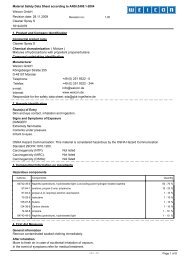
Propylene Glycol Material Safety Data SheetNotificationMANUFACTURER: Houghton Chemical Corporation (Safe-T-Therm)ADDRESS: 52 Cambridge Street, Allston, MA 02134EMERGENCY TELEPHONE: (617) 254-1010, 1-800-777-2466 or Chemtrec 1-800-424-9<strong>300</strong>CHEMICAL NAME & SYNONYMS: Non-toxic AntifreezeCHEMICAL FAMILY: Propylene Glycol BasedFORMULA: Trade SecretCAS REGISTRY NUMBER: Not applicable for blended productDOT SHIPPING CLASSIFICATION: Not RegulatedPRODUCT NUMBER: 510787, 520787, 550787, 560787Hazardous IngredientsMATERIAL CAS # % by Weight TLV (Units)Propylene Glycol 57-55-6 ≈95 Not applicable<strong>Water</strong> 7732-18-5 ≈2 Not applicableCorrosion Inhibitors and Dye TSR#80100075-5002P 3 Not applicablePhysical DataBOILING POINT @760 mm Hg: 311°FFREEZING POINT: -70°FSPECIFIC GRAVITY: 1.06VAPOR PRESSURE AT 20°C: 0.1 mm HgVAPOR DENSITY (air = 1): 2.1SOLUBILITY IN WATER: Complete% VOLATILE BY VOLUME: Greater than 95%EVAPORATION RATE:(H2O=1) Less than 1APPEARANCE AND ODOR: Distinct Orange, OdorlessFire and Explosion Hazard DataFire and Explosion HazardFLASH POINT: 225°FAUTO IGNITION TEMPERATURE: >700°FFLAMMABLE LIMITS IN AIR: ≈2.6 - 12.5EXTINGUISHING MEDIA: Alcohol FoamSPECIAL FIRE FIGHTING PROCEDURES: Not applicableUNUSUAL FIRE AND EXPLOSION HAZARDS: NoneReactivity DataSTABILITY: This material is stable.INCOMPATIBILITY: Keep away from strong oxidizing agents.HAZARDOUS DECOMPOSITION PRODUCTS: Not applicableHAZARDOUS POLYMERIZATION: Will not occurHealth Hazard DataTHRESHOLD LIMIT VALUE: Nuisance Dust 15 mg/M3 8 HoursEFFECTS OF OVEREXPOSURE:• Page 47
Eye Contact: Irritation may result.Skin: No significant signs or symptoms expected.Inhalation: This material is not expected to be a respiratory hazard except if aspirated. If swallowed, can enter lungsand cause damage.Ingestion: If more than several mouthfuls are swallowed, abdominal discomfort, nausea, and diarrhea may occur.Aspiration during ingestion or vomiting may cause lung damage.Emergency and First Aid ProceduresEyes: Flush with water for at least 15 minutes.Skin: Flush with water, wash with mild soap if available.Inhalation: Remove to fresh air.Ingestion: DO NOT induce vomiting, aspiration may cause lung damage; seek medical attention.Spill or Leak ProceduresSTEPS TO BE TAKEN IN CASE THE MATERIAL IS SPILLED OR RELEASED:This liquid is biodegradable but large spills may contaminate public waters. Prevent flow to sewers/public waters.Restrict clean up water use. Notify water supply environment authorities. Impound/recover large land spills. Soak upsmall spills with absorbent material. Use suitable disposal containers. High biodegradability can stimulate algaegrowth. Dispose residue to reduce possible aquatic harm.WASTE DISPOSAL METHOD: Consult with local sewer, municipal, state and/or federal agencies to determineappropriate current disposal options.Special Protective InformationRESPIRATORY PROTECTION: Normally not required.VENTILATION: None needed under anticipated conditions of normal use beyond that needed for normal comfortcontrol.PROTECTIVE GLOVES: If contact with hot liquid possible use suitable protective gloves.EYE PROTECTION: If contact with hot liquid possible use suitable splash goggles and face shield.OTHER PROTECTIVE EQUIPMENT: Not applicablePRECAUTIONS TO BE TAKEN IN HANDLING AND STORAGE:Follow good work/hygiene practices. Provide safety shower and wash in immediate area. Workers should wash with soap and water beforeeating, smoking or using toilet facilities. Launder contaminated clothing before re-use.Note to physician: No specific antidote. Supportive care. Treatment based on judgment of the physician in response to the reaction of thepatient.Notice: No freedom from any patent owned by Seller or others is to be inferred. Because use conditions and applicable laws may differ from onelocation to another and may change with time, Customer is responsible for determining whether products and the information in this documentare appropriate for Customer’s use and for ensuring that Customer’s workplace and disposal practices are in compliance with applicable laws andother governmental enactments. Seller assumes no obligation or liability for the information in this document. NO WARRANTIES ARE GIVEN: ALLIMPLIED WARRANTIES OF MERCHANTABILITY OR FITNESS FOR A PARTICULAR PURPOSE ARE EXPRESSLY EXCLUDED.SAFE-T-THERM ® Propylene Glycol Heat Transfer - Fluid Class IIDESCRIPTIONSAFE-T-THERM ® heat transfer fluid is an inhibited propylene glycol designed for use in hydronic systems. Theinhibitor system is designed to protect metals commonly found in residential and commercial installations such asbrass, copper, solder, steel, and cast iron. The SAFE-T-THERM ® formula also includes an orange dye, for leakdetection, and an antifoam to minimize foaming during service. The effectiveness of SAFE-T-THERM ®• Page 48
heat transfer fluid in preventing corrosion has been proven both in use and in extensive laboratory testing. UsingSAFE-T-THERM ® in place of brine solutions or uninhibited glycol/water solutions lowers maintenance costs andimproves heat transfer efficiency.SAFE-T-THERM ® heat transfer fluid has been formulated with ingredients which are generally recognized as safe(GRAS) by the FDA for use as an aqueous heat transfer medium for closed primary and secondary refrigeration andcooling systems. Components in our formulation conform to the requirements of 21 CFR 184.1666; 21 CFR182.6285; 21 CFR 74.1705, 74.1706 & 74.2340 as applicable. A letter from the USDA can also be provided uponrequest.TYPICAL PROPERTIESColorOrangeDensity, 60°F, lb/gal 8.75Flash Point, TOC, °F 225°pH, 33.33 volume % 9.50Specific Gravity, 60/60°F 1.054Reserve Alkalinity 12.0<strong>Free</strong>ze Protection, °F20% aqueous solution +1830% aqueous solution +840% aqueous solution -850% aqueous solution -27APPLICATIONSLine HeatersSAFE-T-THERM ® heat transfer fluid recommended for use in line heaters. A line heater circulates a heated fluidaround a pipe to raise the temperature of the pipe contents in order to control reactions or ease pumpingoperations.Snow-Melting and Refrigeration <strong>System</strong>sSAFE-T-THERM ® heat transfer fluid is recommended for snow-melting systems for loading ramps, walkways,highways, and airfield runways, and as a coolant in ice rinks and air conditioning systemsCombination <strong>Heating</strong> and Cooling <strong>System</strong>sSAFE-T-THERM ® heat transfer fluid is recommended in combination heating and cooling systems for large buildings.The excellent corrosion protection afforded by SAFE-T-THERM ® heat transfer fluid prolongs the life of the piping inthese systems. SAFE-T-THERM ® heat transfer fluid is also excellent for solar energy collection systems.Thermal Energy Storage <strong>System</strong>sSAFE-T-THERM ® heat transfer fluid is recommended for use in all thermal energy storage systems. The speciallyformulated inhibitor package is designed to protect common system metals from corrosion at glycol concentrationsas low as 20%. For glycol concentrations of less than 20% ask for SAFE-T-THERM ® HD.Quality StatementSAFE-T-THERM ® heat transfer fluid will provide the user a minimum of ten years corrosion and freeze protectionwhen used in conjunction with water of good quality, is the sole product in a properly designed, clean closed andleakfree system and recommended maintenance is implemented based upon testing by Houghton ChemicalCorporation or a laboratory of our choosing once a year.• Page 49
<strong>Free</strong> <strong>Hot</strong> <strong>Water</strong> Label SetInstructions: The following labels must be attached to the relevant valves in the system in order for it to beconsidered <strong>OG</strong>-<strong>300</strong> compliant. This page should be laminated, each label cut from it, punched in the margin at theright hand side and affixed to the appropriate valve with a wire tie, plastic ties are inappropriate due to highoperating temperatures. Failure to affix these labels will void the <strong>SRCC</strong> <strong>OG</strong>-<strong>300</strong> system certification (Refer to page33 Item C and page 35 Item D for placement)Pump Station fill/drain valves (Warning <strong>Hot</strong>)SAFE-T-THERM ® Propylene Glycol Heat Transfer Fluid - AWWA Class IIPlease consult your installation manual for specific freeze toleranceinformation. Valve is closed after filling. Be extremely careful whendraining this fluid. It may be discharged at a very high temperatureand/or pressure. Single Wall Heat Exchanger - NO other fluid shallbe used that would change the original classification of thesystem.Unauthorized alterations to this system could result in ahazardous health condition.Pump Station fill/drain valves (Warning <strong>Hot</strong>)SAFE-T-THERM ® Propylene Glycol Heat Transfer Fluid - AWWA Class IIPlease consult your installation manual for specific freeze toleranceinformation. Valve is closed after filling. Be extremely careful whendraining this fluid. It may be discharged at a very high temperatureand/or pressure. Single Wall Heat Exchanger - NO other fluid shallbe used that would change the original classification of thesystem.Unauthorized alterations to this system could result in ahazardous health condition.Pump Station fill/drain valves (Warning <strong>Hot</strong>) (Refer to page 33 Item C and page 35 Item D for placement)Pump Station fill/drain valves (Warning <strong>Hot</strong>) (Refer to page 33 Item C and page 35 Item D for placement)Collector Array Isolation RETURN Valve (Refer to page 33 Item A and page 35 Item B for placement)Collector Array Isolation SUPPLY Valve (Refer to page 35 Item A for placement and page 12, 13)Cold water supply line isolation ball valve (Refer to page 12, 13)Isolation Valve 15A Normally Open (Refer to page 12, 13)Isolation Valve 15C Normally Open (Refer to page 12, 13)Isolation Valve 1B Normally Closed (Refer to page 12, 13)• Page 50
Collector Array Isolation RETURN ValveValve is normally open during operation. It is closed to isolate the storagetank should the storage tank need servicing or replacing. When closedthe circulating pump is isolated from the solar collector loop piping.Never shut these valves while the circulating pump is in operation.Collector Array Isolation SUPPLY ValveValve is normally open during operation. It is closed to isolate the storagetank should the storage tank need servicing or replacing. When closedthe circulating pump is isolated from the solar collector loop piping.Never shut these valves while the circulating pump is in operation.Cold water supply line isolation ball valve - this valve is normally openand allows potable water to fill the solar storage tank. when closed thesolar storage tankis isolated from the pressurized city cold water supplyline piping.Isolation Valve 15A - page 12Valve is normally open during operation. It is closed to isolate the storagetank should the storage tank need servicing or replacing.Isolation Valve 15C - page 12Valve is normally open during operation. It is closed to isolate the storagetank should the storage tank need servicing or replacing.Isolation Valve - 15B - page 12Valve is normally closed during operation. It is open to isolate the storagetank and 15A and 15C is cloesed should the storage tank need servicingor replacing.FREEZE Instruction: A 50% concentration of propylene glycol anddistilled water can protect your solar system to temperatures as low as -27° f. Lesser concentrations of glycol and distilled water will provide alower level of freeze protection. Please consult section your installationmanual for specific freeze tolerance information.• Page 51
Collectors <strong>System</strong>s Parts List 4002 4003 5002 5003 7002 7003Model # Liberty <strong>Free</strong>dom IndependenceRoof <strong>System</strong> (included based on system) Pitch Flat Pitch Flat Pitch Flat Pitch Flat Pitch Flat Pitch FlatFlat Collector, 4000 Series - <strong>SRCC</strong>#-2010086A FHWC-FC-40220 2 2 3 3Flat Collector, 5000 Series - <strong>SRCC</strong>#-2010087A FHWC-FC-50221 2 2 3 3Flat Collector, 7000 Series - <strong>SRCC</strong>#-2010020A & B FHWC-FC-70275 2 2 3 3Lead <strong>Free</strong> Temperature Control Valve, Thread 3/4" FHWCTCLF1170M2UT012 1 1 1 1 1 1 1 1 1 1 1 1Lag Bolt Hex 3/8" x 5.5", Zinc Plated FHWC-SCZP-HX06-088 4 4 6 6 4 4 6 6 4 4 6 6Elastic Adhesive, <strong>Solar</strong> Flex, White, 290ml FHWM-13750290 1 1 1 1 1 1 1 1 1 1 1 1Union, 22mm, Brass FHWC-UNBR-M022-M22 2 2 4 43/8" Stainless Flat Washers FHWCWA37NWUSS 12 12 18 14 12 12 18 14FHW Single Coil <strong>Solar</strong> Tank 79 gal FHWC-STEN-079-SC 1 1 1 1 1 1FHW Single Coil <strong>Solar</strong> Tank 132 gal FHWC-STEN-132-SC 1 1 1 1 1 1Screw Button Head Socket 3/8" x 1", Stainless Steel FHWC-SCSS-BU06-016 4 4 6 4 4 4 6 4Single-Line Pump Statn-3/4" w/Contr,PRV, Exp.Tank FHWC-PX-SL012-18C1 1 1 1 1 1 1 1 1 1 1 1 1Isolation Valve Threaded, 3/4" FHWCBVLFFBV3C012 1 1 1 1 1 1 1 1 1 1 1 13/8" Hex Nut, Stainless Steel FHWC-NU-SSHX-006 4 4 6 4 4 4 6 42 Collector Mounting Profile, Top and Bottom FHWC-MPAL-50-02 1 1 1 12 Collector Mounting 7000 Series, Top and Bottom FHWC-MPAL-70-02 1 12 Collector Flat Roof Mntg (45 Degrees) FHWC-MFAL-7003-045 1 13 Collector Mounting Profile, Top and Bottom FHWC-MPAL-50-03 1 1 1 13 Collector Mounting 7000 Series, Top and Bottom FHWC-MPAL-70-03 1 13 Collector Flat Roof Mntg (45 Degrees) FHWC-MFAL-7003-045 1 1 ? 1Lag Bolt Hex 3/8" x 5.5", Zinc Plated FHWC-SCZP-HX06-088 4 6 4 6 4 6Composition Roof Bracket FHWC-BKAL-CS 4 6 4 6 4 6Flat Washer 3/8", Zinc Plated FHWC-WAZP-06 4 6Barrel Union - 3/4" Male/Male, Brass FHWC-UNBR-1212MM 2 2 4 4Washer M8 A2, Stainless Steel FHWC-WASS-M8-A2 8 8 12 12Screw M8 x 30 A2, Stainless Steel FHWC-SCSS-M8A2-030 8 8 12 12Flat Washer, 7/16", Stainless Steel FHWC-WASS-07 12 18 12 187/16" Hex Nut, Stainless Steel FHWC-NU-SSHX-007 4 6Screw Hex 7/16" x 1.25", Stainless Steel FHWC-SCSS-HX07-020 4 6Mounting Clamp - 7000 Series FHWC-CLAL-70 4 6Connection Kits (included)3/4" Air Vent, Brass, Male Connector FHWC-VN-BRML-012 1 1 1 1 1 1 1 1 1 1 1 1Brass Threaded Tee, 3/4" FHWC-NTBR-121212-FFF 1 1 1 1 1 1 1 1 1 1 1 1Brass Thread 90 Deg St.Elbow, 3/4"(MF) FHWC-NBBR-1212-MF090 2 2 2 2 2 2 2 2 1 1 1 1Close Nipple, NPT 3/4", NPT 3/4", Red Brass FHWC-NCBR-N012-N12 1 1 1 1 1 1 1 1Female Connector, 22mm, NPT 3/4", Brass FHWC-FNBR-M022-N12 2 2 2 2PT 3/4" Plug for Collector Connection FHWC-PGBR-012 2 2 2 2 2 2 2 2Hex Nipple, G 1", NPT 3/4", Brass FHWC-HNBR-G016-N12 1 1 1 1Brass Threaded 90 Degree Elbow, 3/4" FHWC-NBBR-1212-MF090 1 1 1 1Adaptor, G 1", NPT 3/4", Brass FHWC-ADBR-G016-N12 1 1 1 1Optional Pumping Solutions (upgrade)Dual-Line Pump Statn-3/4" w/Contr,PRV,Exp.Tank FHWC-PX-DL012-18C3 optional upgrade optional upgradeDual-Line Pump Statn-3/4" w/Cntrllr,PRV,Flow,Exp.Tank FHWC-PX-DL012-18C4 optional upgrade optional upgradeOptional Piping (not included)SS Dual Helical Flex Hose,R6 insulated 3/4" w/wire FHWC-FHSS-H2WI-NY012 based on length of run based on length of run based on length of runGraphite Flex Hose Female Connection Fitting - 3/4" FHWC-HCBR-N12-FM based on connections based on connections based on connectionsGraphite Flex Hose Male Connection Fitting-3/4" FHWC-HCBR-N12-ML based on connections based on connections based on connectionsCopper pipe 3/4" and connections Mfg. does. Not sell based on length of run based on length of run based on length of runMaterials (not included) 50% antifreeze / 50% water mix - freeze point -25°FGlycol / Distilled <strong>Water</strong> 50% Mix For Collectors FHWM-GY-50005 1.2 1.2 1.8 1.8 2.2 2.2 3.3 3.3 1 1 1.5 1.5• Page 52
Glycol / Distilled <strong>Water</strong> Mix For 3/4" pipe per 100' Basic calculation 2.3 2.3 2.3 2.3 2.3 2.3 2.3 2.3 2.3 2.3 2.3 2.3Trouble ShootingA properly maintained solar water heating system can provide years of dependable trouble free service. It issuggested that routine preventive maintenance program be established and followed by the end user with hiscontractor. Listed below is the maintenance check list that outlines the primary components of the solar system thatneed to be inspected annually. See page 37 for additional information.1. Propylene glycol – It is very important that the quality of the propylene glycol heat transfer fluid ismaintained to avoid damage to the collector loop and related components which come in contact with thefluid. See the propylene glycol Data Sheet located in the back of the manual for further details.2. <strong>Water</strong> quality can affect the operation of the solar heat exchanger over time. In very hard water areas, it isrecommended you drain a few gallons of water from the storage tank to keep the bottom of the tank freeof sediment.3. Inspect and clean the solar collectors of any dirt, leaves, debris or film that may have settled on the surfaceand may affect the performance. Clean by spraying with a pressurized water hose only.4. Check Insulation for deterioration.5. Check solar tank sensors and the collector sensor to assure that they are secure and have not moved orloosened.6. Inspect the T&P valve on the water heater. Lift the release handle lever and make discharge is directed toan open drain. Always remove sediment from tank prior to testing T&P valve.7. The area near the water heater must be kept free of flammable liquids such as gasoline, paint thinners,adhesive or other combustible materials.8. Anode rod Inspection – The anode rod should be removed from the water heater tank annually forinspection. It is important to turn off the power to the heater and run water until it is cold, then drain tankand replace the anode rod. See page 52 for additional information.Shut down proceduresThe solar system is designed to be easily isolated for emergency repairs or routine maintenance. To isolate thewater heater, simply shut down the supply water shut off valve which isolates the water heater from thepressurized cold water supply. The collector loop can be isolated from the solar storage tank by closing the collectorarray “hot” and “cold” line isolation valves. If the pressure in this loop drops or you find a glycol leak, close thesevalves and turn the circulating pump off by shutting down the power to the control, then contact your installationcontractor.• Page 53
Nature of trouble Possible cause ServiceNot enough hot water.<strong>System</strong> undersized.Defective element.Defective thermostat or wiredincorrectly.<strong>Solar</strong> system controller incorrectlyinstalled.Leaking plumbing or open hot waterfaucet(s).Reduce rate of hot water use.Check amperage, replace element.Check wiring or replace.Check Installation.Make sure all faucet(s) are closed and checkwater meter.<strong>Water</strong> too hot or not hot Thermostat setting too high or low. Change setting as required.enough. Thermostat out of calibration. ReplacePump does not operate (even thoughthere is solar radiation and the tank iscold).<strong>Solar</strong> system incorrectly installed.No power to pump.Controller improperly set.Sensor out of position.Sensor defective.Pump defective.Check installation.Check controller and pump wiring.Check program - Refer to pump stationmanual “Control parameter” section.Check position of all sensors.Check sensor resistance - Refer to controllermanual “Tips for Fault Localization” section.Replace pump.Warning: For your safety, do not attempt repair of electrical wiring, thermostat, heating element or otheroperating controls. Refer repairs to qualified service personnel.• Page 54
Nature of trouble Possible cause ServicePump operates intermittently.<strong>System</strong> pressure too high.<strong>System</strong> pressure too low.Temperature differential betweencollector and storage tank too high.Pump operates at night.Storage tank cools down rapidly.Normal when weather changes.Sensors connected to wrongterminals.Improper system “switch-on” or“switch-off” temperature.Sensor out of position.Filling pressure too high.Expansion tank initial pressure toohigh.Expansion tank too small.Propylene glycol leak in system.Expansion tank too small (release ofpropylene glycol from relief valve).Controller improperly set or sensordefective.Controller improperly set.Sensor out of position.No power to pump.Air or impurities present in system.Pump defective.Normal on very warm nights.Check valve open or dirty.Controller defective.Consumption higher than design forsystem.Check valve open or dirty.Insulation defective or inadequate.None.Check sensor connections - Refer tocontroller manual “Installation” section.Check sensor resistance - Refer to controllermanual “Control parameter” section.Secure sensor properly.Adjust system pressure to 50 psi (3.5 bar).Isolate and adjust expansion tank to 40 psi(2.8 bar).Properly size and replace expansion tank.Check system for leaks and repair.Properly size and replace expansion tank.Check program - Refer to controller manual“Control parameter” section.Check program - Refer to controller manual“Control parameter” section.Secure sensor properly.Check controller and pump wiring.Properly commission system, purge all air.Replace pump.None.Check position of check valves, clean orreplace if necessary.Replace controller.Reduce rate of hot water use.Check position of check valves, clean orreplace if necessary.Add, repair, or replace pipe insulation asneeded.• Page 55
Vacation Planning<strong>Solar</strong> water heaters can build up very high temperatures when there is no daily draw on the system. Your <strong>Free</strong> <strong>Hot</strong><strong>Water</strong> solar water heating system controller is programmed to protect your system from overheating. When leavingyour home for extended periods of time, no special shut down procedures are required. The best way to protectyour system is to make sure power is always on and to keep the system in normal operating mode. . The systemcontroller will use the collectors to radiate heat back to the atmosphere , preventing the system from stagnating atvery high temperatures.Following installation of the T & P Relief Valve, the valve lever MUST be operated AT LEAST ONCE A YEARby the water heater owner to ensure that waterways are clear. Certain naturally occurring mineraldeposits may adhere to the valve, blocking waterways, rendering it inoperative. When the lever isoperated, hot water will discharge if the waterways are clear. PRECAUTIONS MUST BE TAKEN TO AVOIDPERSONAL INJURY FROM CONTACT WITH HOT WATER AND TO AVOID PROPERTY DAMAGE. BEFOREoperating lever, check to see that a discharge line is connected to the valve, directing the flow of hotwater from the valve to a proper place of disposal. If no water flows when the lever is operated,replacement of the valve is required. TURN THE WATER HEATER “OFF” AND CALL A PLUMBERIMMEDIATELY. This device is designed for emergency safety relief and shall not be used as an operatingcontrol. A relief valve functions, in an emergency, by discharging water. Therefore, it is essential that adischarge line be piped from the valve in order to carry the overflow to a safe place of disposal. Thedischarge line must be the same size as the valve outlet and must pitch downward from the valveand terminate at least 6” above a drain where any discharge will be clearly visible.• Page 56
Maintenance NotesNotes• Page 57
Installer informationInstallers name:__________________________________________________Company:_______________________________________________________Address 1:_______________________________________________________Address 2:_______________________________________________________City: State: Zip:___________________________________________________Phone number:___________________________________________________Fax number:_____________________________________________________E-mail:__________________________________________________________Installation informationCollectors: Model number: Serial number:_____________________________1.___________________ 2.___________________ 3.____________________Tank: Gallons: Existing:_____________________________________________Orientation: Pitch:________________________________________________Installed date:____________________________________________________Guarantee and WarrantyNo liability will be assumed for use other than for the intended purpose or for inadmissible alteration of installationcomponents or consequences thereof; likewise for failure to observe the installation instructions correctly. Allinformation and instructions in this manual refer to the current state of development. Please always use therespective assembly instructions supplied with the collectors. Figures and illustrations used. Due to the possibility ofsetting and printing errors, and to the need for continuous technical change, please understand that we cannotaccept liability for the correctness of the data. The most current version of the General terms of Business wouldalways prevail.All photographs used are for illustrative purposes only. These assembly instructions contain proprietary informationprotected by copyright laws. All rights and changes to these assembly instructions are reserved.• Page 58
• Page 59