Handleiding-CMFe - Wolter en dros
Handleiding-CMFe - Wolter en dros
Handleiding-CMFe - Wolter en dros

Create successful ePaper yourself
Turn your PDF publications into a flip-book with our unique Google optimized e-Paper software.
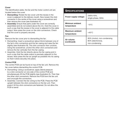
Cover<br />
The id<strong>en</strong>tification plate, the fan and the motor control unit are<br />
located below the cover.<br />
• Dismantling: Rotate the fan cover until the recess in the<br />
cover is adjac<strong>en</strong>t to the delivery mouth. Now loos<strong>en</strong> the click<br />
connector in the c<strong>en</strong>tre of the cover using a screwdriver and<br />
th<strong>en</strong> remove the cover (see illustration A).<br />
• Assembly: Ensure that parts under the cover are correctly<br />
assembled and do not ext<strong>en</strong>d above the rim. Hold the cover in<br />
such a way that the recess in the cover is adjac<strong>en</strong>t to the cable<br />
output. Now press the cover on the click connectors. Check<br />
that the cover is properly secured.<br />
Fan<br />
Remove the fan cover prior to dismantling the fan.<br />
• Dismantling: Insert a screwdriver (about 8mm) betwe<strong>en</strong> one of<br />
the fan’s click connectors and the fan casing and raise the fan<br />
slightly (see illustration B). The click connector th<strong>en</strong> unclicks.<br />
Using the screwdriver, unclick the other click connectors and<br />
remove the fan vertically from the fan casing.<br />
• Assembly: Hold the fan directly above the fan casing and in<br />
such a way that the cable output is precisely adjac<strong>en</strong>t to the<br />
recess. Now press the fan as upright as possible into its casing<br />
so that it clicks securely into place.<br />
Control PCB<br />
The control PCB can be found on top of the fan unit. Remove the<br />
fan cover before dismantling the control PCB.<br />
• Dismantling: Using a screwdriver, apply lateral pressure<br />
to a click connector on one side of the control PCB and<br />
simultaneously lift the PCB slightly (see illustration E). Th<strong>en</strong> free<br />
the other click connectors. Remove the PCB from the fan unit<br />
and uncouple the connectors.<br />
• Assembly: Connect the fan wiring to the PCB. Press the PCB<br />
upright betwe<strong>en</strong> the click connectors on the fan unit. Th<strong>en</strong><br />
press it till the click connectors are fast<strong>en</strong>ed. Do not allow the<br />
PCB to b<strong>en</strong>d!<br />
SPECIFICATIONS<br />
Power supply voltage:<br />
Minimum ambi<strong>en</strong>t<br />
temperature<br />
Maximum ambi<strong>en</strong>t<br />
temperature:<br />
Air volume<br />
(continued):<br />
230V±10%,<br />
single-phase, 50Hz<br />
-10°C<br />
+40°C<br />
95% (motor), non-cond<strong>en</strong>sing<br />
85% (electronics),<br />
non-cond<strong>en</strong>sing