SR 25, SR38, SR 65, SR68, SR 75 (S) - WEKA Elektrowerkzeuge
SR 25, SR38, SR 65, SR68, SR 75 (S) - WEKA Elektrowerkzeuge
SR 25, SR38, SR 65, SR68, SR 75 (S) - WEKA Elektrowerkzeuge

Create successful ePaper yourself
Turn your PDF publications into a flip-book with our unique Google optimized e-Paper software.
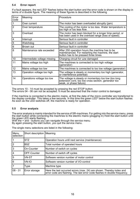
5.4 Error report<br />
If a fault appears, the red LED* flashes below the start button and the error code is shown on the display in<br />
terms of a double figure. The meaning of these figures is described in the following<br />
Error<br />
code<br />
Meaning Procedure<br />
1 Over current The motor has been overloaded abruptly (jam)<br />
2 Over temperature The cooling of the motor is too less. Water temperature is<br />
too high or too less flow.<br />
3 Overload The motor has been blocked for a longer time period, or<br />
has been used in the overload range (loss of speed).<br />
4 Interrupt Serious fault in controller<br />
5 Watchdog Serious fault in controller<br />
6 Brown out Serious fault in controller<br />
8 Maintenance rate exceeded After <strong>25</strong>0 operation hours the machine has to be<br />
maintenanced. For restarting the machine, the start<br />
button has to be pressed three times.<br />
10 Intermediate voltage missing Charging circuit for uzw damaged<br />
11 Mains voltage too high The machines is connected to too high voltage<br />
(generator)<br />
12 Mains voltage too low The machines is connected to too low voltage (generator)<br />
13 Operation voltage too high The voltage is steady or momentary too high (generator,<br />
or interference potential)<br />
14 Operations voltage too low The voltage is steady or momentary too low (too long<br />
extension cord, too low cross section, generator too<br />
weak, or phase failure)<br />
The errors 10 - 14 must be accepted by pressing the red STOP button.<br />
The errors 04 - 06 can not be accepted. It must be assumed that the motor control is damaged.<br />
If the machine is connected to the electric mains, at first the data of the micro controller are transferred to<br />
the display controller. This takes a few seconds. In this time the green LED* below the start button flashes.<br />
As soon as the LED switches off, the machine is ready for operation.<br />
5.5 Error analysis<br />
The error analysis is mainly intended for the service of <strong>SR</strong>-machines. For getting into the service menu, press<br />
the start button while connecting the machines to the electric mains (plugging in) Hold the start button until<br />
the green LED starts flashing.<br />
With the + and - buttons you can navigate through the service menu.<br />
By again pressing the start button, you quit the service menu.<br />
The single menu selections are listed in the following:<br />
Menu<br />
selection<br />
Short description Meaning<br />
1 STZ Operation hours until next service (maintenance)<br />
2 BSZ Total number of operated hours<br />
3 On-Counter Number of switch on cycles<br />
4 OFF-Counter Number of switch off cycles<br />
5 VN-ST Software version number of motor control<br />
6 VN-IO Software version number of I/O-control<br />
7 Type Machine type<br />
08 - 31 Error storage Here the last occurred errors (max. 24) are shown. Thereby index and<br />
error code are flashing. The last error code flashes in double frequency.<br />
16