Jøtul FS 162 - 370 - Jøtul stoves and fireplaces
Jøtul FS 162 - 370 - Jøtul stoves and fireplaces
Jøtul FS 162 - 370 - Jøtul stoves and fireplaces

Create successful ePaper yourself
Turn your PDF publications into a flip-book with our unique Google optimized e-Paper software.
ENGLISH<br />
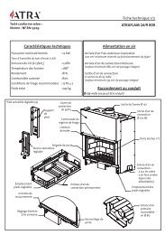
9. Fit a flex hose for combustion air (part 21). See fig. 3. If<br />
necessary, this can be fitted later, depending on the distance<br />
to the wall. See fig. 11 B+C.<br />
10. Fit the ornamental stones (part 12) against the back of the<br />
side frames using the relevant screws, see Fig. 4. These are<br />
adjusted after being mounted on the surround.<br />
4.2 Chimney <strong>and</strong> flue pipe<br />
• The product can be connected to a chimney <strong>and</strong> flue pipe<br />
approved for solid fuel products with flue gas temperatures<br />
as specified in “2.0 Technical data” in the “Jøtul F <strong>370</strong> series”<br />
manual.<br />
• The cross section of the chimney must be at least that of<br />
the flue pipe. See “2.0 Technical data” in the “Jøtul F <strong>370</strong><br />
series” manual when calculating the correct chimney cross<br />
section.<br />
• Several solid fuel products can be connected to the same<br />
chimney system if the chimney cross section is adequate.<br />
• Connection to the chimney must be performed in accordance<br />
with the installation instructions of the chimney supplier.<br />
• Make sure that the flue pipe rises all the way between the<br />
product <strong>and</strong> the chimney at the rear outlet.<br />
• Please note that it is extremely important for connections to<br />
have a degree of flexibility.<br />
For recommended chimney draught, see “2.0 Technical data” in<br />
the “Jøtul F <strong>370</strong>-series” manual.<br />
Flue pipe at top outlet - fig. 5<br />
The product is supplied from the factory with smoke outlet fitted<br />
for the top outlet. A 60 mm offset pipe (optional extra) must be<br />
used when top-mounting a flue pipe or steel chimney.<br />
1. Place the gasket on the edge of the offset pipe (Fig. 5A).<br />
2. Fit the end of the offset pipe with the gasket into the smoke<br />
outlet (Fig. 5B).<br />
3. Check that the whole of the gasket is correctly positioned.<br />
4. Remove the knockout in the valve plate 1 <strong>and</strong> 2 (part 19+20)<br />
on the top of the product.<br />
4.3 Installation<br />
Necessary tools: Spirit level, measuring tape <strong>and</strong> rubber mallet.<br />
NB: The base must be level. Max. 1 mm/m tolerance. This is<br />
extremely important to ensure that the rest of the installation<br />
is correct.<br />
All stones must be level. This has to be checked for each new<br />
layer of stones.<br />
Important!<br />
Bear in mind that the soap stones may be damaged if they are<br />
h<strong>and</strong>led roughly. Do not knock the mounting brackets too hard.<br />
Installation should be carried out by a qualified person.<br />
The soap stones are heavy <strong>and</strong> should be h<strong>and</strong>led with care<br />
during unpacking. Place unpacked stones on a soft base.<br />
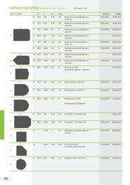
The surround consists of the following parts<br />
– see fig. 6:<br />
Part Designation Quantity<br />
1 Bottom stone 1<br />
2 Bottom stone w/ knockout 1<br />
3 Soap stone, bottom layer 6<br />
4 Side stone w/ convection hole, right 1<br />
5 Side stone w/ convection hole, left 1<br />
6 Cover for convection hole 2<br />
7 Load-bearing plate 1<br />
8 Locking bracket 1<br />
9 Cover plate, lower 1<br />
10 Side cartridge, left 1<br />
11 Side cartridge, right 1<br />
12 Ornamental stone 4<br />
13 Cover plate, upper 1<br />
14 Wedges 2<br />
15 Side stone (2 extra) 16<br />
16 Side stone for smoke outlet, left 1<br />
17 Side stone for smoke outlet, right 1<br />
18 Top stone 2<br />
19 Valve plate 1 1<br />
20 Valve plate 2 1<br />
21 Flex hose 1<br />
22 Hose clamp 1<br />
23 Nut 4<br />
24 Spacer sleeve 4<br />
25 Threaded bolt 4<br />
26 Screw, for ornamental stone 8<br />
27 Mounting bracket, single w/ angle 22<br />
28 Mounting bracket, 3/2 - left 2<br />
29 Mounting bracket, double w/ angle 8<br />
30 Mounting bracket, single 2<br />
31 Mounting bracket, 3/2 - right 2<br />
32 Screw, M8 x 25 1<br />
33 Floor plate (optional extra) 1<br />
1. The two bottom stones (parts 1 <strong>and</strong> 2) are put in place. See<br />
fig. 7. Check using a spirit level, then adjust as necessary. It<br />
is extremely important that the bottom plate be steady <strong>and</strong><br />
level.<br />
2. Fit the bottom layer using soap stone (part 3). Start with the<br />
two rear stones with convection holes (parts 4 <strong>and</strong> 5). See fig. 8.<br />
Adjust the stones so that the joints are flush with the joints in<br />
the bottom plate, fig. 8A. Also make sure that the edges of the<br />
bottom stones are at the same distance all the way around,<br />
fig. 9B.<br />
3. Insert the two covers for convection holes (part 6) on the back,<br />
fig. 10. The covers are attached onto the surround by folding<br />
the two tabs to the side on the inside of the hole. Make sure<br />
that they fit snugly.<br />
4. Put the load-bearing plate (part 7) in position. See fig. 9C. NB!<br />
It is extremely important that the plate is the right way round.<br />
The slot must be on the right-h<strong>and</strong> side. See fig. 9 D.<br />
5. When using an external air connection (optional extra, cat. no.<br />
341296), this has to be fitted now. Position the burn chamber<br />
in the four holes in the load-bearing plate, fig. 11. Make sure<br />
that the flexible tube for combustion air is not trapped. This<br />
tube is passed through an opening in the bottom stone. If<br />
external air connection is not going to be used, cut the flex<br />
hose at the outer edge of the opening. Suggested installation<br />
of the flex hose for combustion air: See fig. 11B <strong>and</strong> C. Remove<br />
the pieces of wood carefully so that the burn chamber does<br />
not topple over. Installation completed: See fig. 11 D.<br />
22