KS2005E - Service - Black & Decker
KS2005E - Service - Black & Decker
KS2005E - Service - Black & Decker

You also want an ePaper? Increase the reach of your titles
YUMPU automatically turns print PDFs into web optimized ePapers that Google loves.
ENGLISH<br />
When assessing vibration exposure to determine safety<br />
measures required by 2002/44/EC to protect persons regularly<br />
using power tools in employment, an estimation of vibration<br />
exposure should consider, the actual conditions of use and the<br />
way the tool is used, including taking account of all parts of the<br />
operating cycle such as the times when the tool is switched off<br />
and when it is running idle in addition to the trigger time.<br />
Labels on tool<br />
The following pictograms are shown on the tool:<br />
:<br />
Warning! To reduce the risk of injury, the user must<br />
read the instruction manual.<br />
Electrical safety<br />
#<br />
This tool is double insulated; therefore no earth wire<br />
is required. Always check that the power supply<br />
corresponds to the voltage on the rating plate.<br />
u If the supply cord is damaged, it must be replaced by the<br />
manufacturer or an authorised <strong>Black</strong> & <strong>Decker</strong> <strong>Service</strong><br />
Centre in order to avoid a hazard.<br />
Features<br />
This tool includes some or all of the following features.<br />
1. On/off switch<br />
2. Lock-on button<br />
3. Variable speed control knob<br />
4. Mode selector switch<br />
5. Saw blade locking lever<br />
6. Saw blade holder<br />
7. Shoe plate<br />
8. Shoe plate locking knob<br />
9. Scroll knob<br />
10. Saw blade storage compartment<br />
Assembly<br />
Warning! Before assembly, make sure that the tool is<br />
switched off and unplugged.<br />
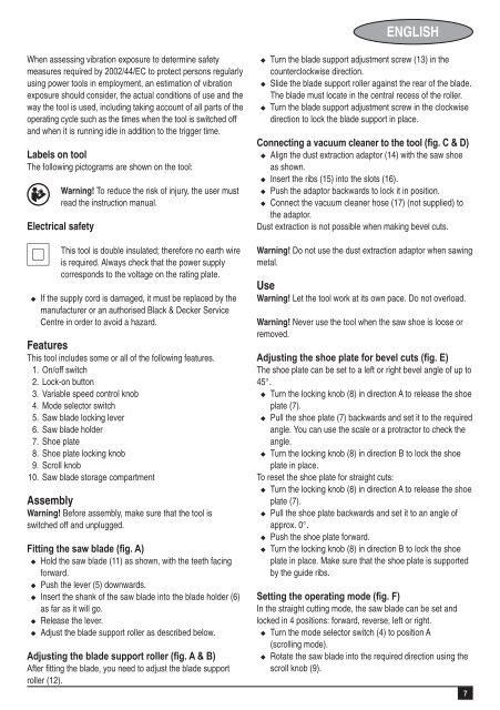
Fitting the saw blade (fig. A)<br />
u Hold the saw blade (11) as shown, with the teeth facing<br />
forward.<br />
u Push the lever (5) downwards.<br />
u Insert the shank of the saw blade into the blade holder (6)<br />
as far as it will go.<br />
u Release the lever.<br />
u Adjust the blade support roller as described below.<br />
Adjusting the blade support roller (fig. A & B)<br />
After fitting the blade, you need to adjust the blade support<br />
roller (12).<br />
u Turn the blade support adjustment screw (13) in the<br />
counterclockwise direction.<br />
u Slide the blade support roller against the rear of the blade.<br />
The blade must locate in the central recess of the roller.<br />
u Turn the blade support adjustment screw in the clockwise<br />
direction to lock the blade support in place.<br />
Connecting a vacuum cleaner to the tool (fig. C & D)<br />
u Align the dust extraction adaptor (14) with the saw shoe<br />
as shown.<br />
u Insert the ribs (15) into the slots (16).<br />
u Push the adaptor backwards to lock it in position.<br />
u Connect the vacuum cleaner hose (17) (not supplied) to<br />
the adaptor.<br />
Dust extraction is not possible when making bevel cuts.<br />
Warning! Do not use the dust extraction adaptor when sawing<br />
metal.<br />
Use<br />
Warning! Let the tool work at its own pace. Do not overload.<br />
Warning! Never use the tool when the saw shoe is loose or<br />
removed.<br />
Adjusting the shoe plate for bevel cuts (fig. E)<br />
The shoe plate can be set to a left or right bevel angle of up to<br />
45°.<br />
u Turn the locking knob (8) in direction A to release the shoe<br />
plate (7).<br />
u Pull the shoe plate (7) backwards and set it to the required<br />
angle. You can use the scale or a protractor to check the<br />
angle.<br />
u Turn the locking knob (8) in direction B to lock the shoe<br />
plate in place.<br />
To reset the shoe plate for straight cuts:<br />
u Turn the locking knob (8) in direction A to release the shoe<br />
plate (7).<br />
u Pull the shoe plate backwards and set it to an angle of<br />
approx. 0°.<br />
u Push the shoe plate forward.<br />
u Turn the locking knob (8) in direction B to lock the shoe<br />
plate in place. Make sure that the shoe plate is supported<br />
by the guide ribs.<br />
Setting the operating mode (fig. F)<br />
In the straight cutting mode, the saw blade can be set and<br />
locked in 4 positions: forward, reverse, left or right.<br />
u Turn the mode selector switch (4) to position A<br />
(scrolling mode).<br />
u Rotate the saw blade into the required direction using the<br />
scroll knob (9).<br />
7