D GB E DK P Motormodul MZ2 MM2x8A Technische ... - Essmann
D GB E DK P Motormodul MZ2 MM2x8A Technische ... - Essmann
D GB E DK P Motormodul MZ2 MM2x8A Technische ... - Essmann

You also want an ePaper? Increase the reach of your titles
YUMPU automatically turns print PDFs into web optimized ePapers that Google loves.
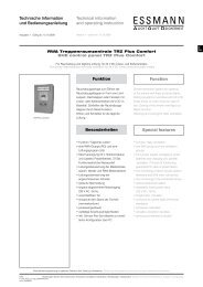
<strong>Motormodul</strong> <strong>MZ2</strong> <strong>MM2x8A</strong><strong>Motormodul</strong> <strong>MZ2</strong> <strong>MM2x8A</strong>Steuermodul für Antriebe in 2 Motorkreisen mit je 8 Ampere obere KlemmreiheEinsatzbereichDiese Komponente der Modulzentrale <strong>MZ2</strong> dient als Aktormodul mitÜberwachungsfunktion zur Steuerung von zwei Aktorkreisen, mit jeweils max.8 A Last.Als Aktoren sind 24 V DC Linearantriebe und Haftmagneten zugelassen. JederAktorkreis lässt sich separat aktivieren und steuern. Je nach Aktortyp stehenverschiedene Funktionen zur Auswahl. Jedes Modul erhält eine über einenDrehkodierschalter einstellbare Adresse zwischen 1 und 15. Somit können ineiner <strong>MZ2</strong> bis zu 15 Module diesen Typs betrieben werden.Besonderheiten• Anschlussmöglichkeit von 24 V DC RWA- und Lüftungsantrieben• Anschlussmöglichkeit von Haftmagneten• Die LED-Anzeige signalisiert Betriebszustände und Fehler• Meldeausgang “AUF”• Schnapp-Montage auf Montageschiene mit Busklemmen<strong>MM2x8A</strong>• Lüftungshubbegrenzung• Nachtriggerung nach VdS (Blockade-Funktion)• Stromsparmodus (Abschaltung der Aktor-Ausgänge)Diese Bedienungsanleitung für späteren Gebrauch bzw. Wartung aufbewahren. Änderungen dienen dem technischen Fortschritt und bleiben vorbehalten. Abbildungen unverbindlich.03/24999739 3
<strong>Motormodul</strong> <strong>MZ2</strong> <strong>MM2x8A</strong>Klemmbelegungobere Klemmreihe(i.d.R. die Anschlussleiste für den Monteur)Die Nummerierung der Anschlussklemmen erfolgt bei allen<strong>MZ2</strong>-Modulen nach dem gleichen Prinzip. (Ausnahme Netzmodul NM16A).. . .. . .. . .. . . 5 6 7 81 2 3 4 . . . 1 2 3 41 2 3 45 6 7 8Modul-Draufsicht:Begonnen wird bei links oben.Jede Ebene tiefer wird die Nummerierung fortgeführt, links beginnend.<strong>MZ2</strong>Modul<strong>MM2x8A</strong>OKABDie Nummerierung der unteren Klemmreihe wird nach dem obenbeschriebenen Verfahren bei ‚ fortgeführt.9 10 11 12. . .. . .9 10 11 12. . .. . .13 14 15 1613 14 15 16. . . . . .untere Klemmreihe(i.d.R. werksseitig vorverdrahtet oder nicht belegt)AnschlüsseDie Lage der Klemmen und die Verdrahtung mit den <strong>MZ2</strong>-Netzteil und Aktorenentnehmen Sie bitte dem Klemmplan.Motorkreis AbraunAchtung: Jede Klemme ist mit maximal 12 A belastbar! Das Modul darfniemals bei eingeschalteter Versorgung auf die Hutschiene montiert werden,das führt zur Zerstörung des Moduls und der externen Aktorkreis-Überwachungsdioden.Klemme 1: Ausgang Aktorkreis A (-) (bezogen auf: Fahrtrichtung „Auf“)Klemme 2: Ausgang Aktorkreis A (+) (bezogen auf: Fahrtrichtung „Auf“)MblauAusgang “Auf”Klemme 3: Überwachungsleitung Aktorkreis AKlemme 4: Ausgang „Auf-Anzeige“ für Aktorkreis A (+24 V gegen Masse).Spannungslos im "Notbetrieb"Klemme 9: 24 V Versorgung Aktorkreis AAA1 2 3 49 10 11 12Klemme 10: 24 V Versorgung Aktorkreis A (intern gebrückt zu Klemme 9)Klemme 11: Masse Versorgung Aktorkreis AKlemme 12: Masse Versorgung Aktorkreis A (intern gebrückt zu Klemme 11)+ 24V- GNDMotorkreis B+ 24V- GN<strong>DK</strong>lemme 5: Ausgang Aktorkreis B (-) (bezogen auf: Fahrtrichtung „Auf“)Klemme 6: Ausgang Aktorkreis B (+) (bezogen auf: Fahrtrichtung „Auf“)Klemme 7: Überwachungsleitung Aktorkreis BMbraunblauKlemme 8: Ausgang „Auf-Anzeige“ für Aktorkreis B (+24 V gegen Masse)Spannungslos im "Notbetrieb"Klemme 13: 24 V Versorgung Aktorkreis BAusgang “Auf”Klemme 14: 24 V Versorgung Aktorkreis B (intern gebrückt zu Klemme13)Klemme 15: Masse Versorgung Aktorkreis BB5 6 7 8Klemme 16: Masse Versorgung Aktorkreis B (intern gebrückt zu Klemme 15)B13 14 15 16+ 24V + 24V- GND - GND4 03/24999739
<strong>Motormodul</strong> <strong>MZ2</strong> <strong>MM2x8A</strong>Bedien- & AnzeigeelementeDie Lage der Elemente entnehmen Sie bitte dem Aufbauplan.AdresswahlschalterStellung 0: Modul abgeschaltet.Achtung: Die Stromaufnahme bleibt unverändert.Stellung 1 - F: Moduladressen 1 bis 15 eingestellt (siehe PC SoftwareBeschreibung).MM 2 x 8AOKABLED „OK“Farbe: GrünFunktion: Betriebsanzeige.LED leuchtet, wenn das Modul im System eingebunden ist und über einegültige Initialisierung verfügt.LED blinkt (kurze Pulse), wenn sich das Modul im Notbetrieb befindet.LED AFarbe: GelbFunktion: Störung Aktorkreis A.LED leuchtet, wenn Modul nicht initialisiert ist, oder der Prozessor nichtarbeitet.LED blinkt, wenn eine Störung vorliegt. Aus dem Blinkrhythmus kann derbestehende Fehler ermittelt werden. (Siehe hierzu die Tabelle Blinkcodes).LED BFarbe: GelbFunktion: Störung Aktorkreis B(siehe LED A).Funktionen für die <strong>MZ2</strong>Das Modul stellt folgende Funktionen bereit, die im Einzelnen durch die PC Software konfiguriert und durch dasMCU-Modul und die GM-Module gesteuert werden. Die bei den Selbsttests und Testfunktionen erkannten Fehlerwerden über die LED A oder B signalisiert und an das MCU-Modul und an die GM-Module übertragen (sieheauch die Tabelle Blinkcodes).Gemeinsame Funktionen für alle AktorenLeitungsüberwachungDas Modul überwacht die Aktor-Zuleitungen auf Unterbrechung.Überwachung der VersorgungsspannungenDas Modul überwacht die Spannungsversorgung der Aktorkreise.Überwachung der AusgangsspannungenDas Modul überwacht die an den Aktorausgängen anliegende Spannung.Hierbei wird auch die der Funktion entsprechende Polarität geprüft.03/249997395
<strong>Motormodul</strong> <strong>MZ2</strong> <strong>MM2x8A</strong>Funktionen für die <strong>MZ2</strong>Sicherung des Betriebszustand RWA-AuslösungTritt während des Betriebszustandes „RWA-Auslösung“ eine Unterbrechungder Versorgungsspannung oder der Kommunikation zur MCU auf, so bleibt derZustand trotzdem im Modul gespeichert und wird nach der Spannungsunterbrechungunabhängig von der MCU wieder hergestellt.Funktionen für LinearantriebeDie einzelnen Betriebszustände werden vom MCU Modul gesteuert.Betriebszustand „Ruhestellung“Die Motorkreise sind stromlos geschaltet.Betriebszustand „Notbetrieb“Um sicherzustellen, dass alle Antriebe in Position „Zu“ sind, werden bei Eintrittin diesen Zustand die Motorkreise ca. drei Minuten in Fahrtrichtung „Zu “unddanach spannungslos geschaltet. Die Funktion „Ausgang freischalten“ istdeaktiviert.Alle Lüftungsfunktionen sind gesperrt.Es wird nur der Wechsel in den Betriebszustand „RWA-Auslösung“ und dieAufhebung dieses Zustandes akzeptiert. Ein aktiver Ausgang an Klemme 4oder 8 wird spannungslos geschaltet.Betriebszustand „RWA-Auslösung“Der Motorkreis wird in Fahrtrichtung „Auf“ geschaltet.Ist die Option „Nachtriggern“ aktiviert, wird sechzehn Mal im Abstand von dreiMinuten der Motorkreis ca. 3 Sekunden lang in Fahrtrichtung „Zu“ undanschließend wieder in Fahrtrichtung „Auf“ geschaltet.Alle anderen Funktionen z. B. die Lüftungsfunktionen sind gesperrt.Wird der Betriebszustand mit „RWA-Reset“ beendet, dann wird der Motorkreisspannungslos geschaltet.Wird der Betriebszustand mit „RWA-Zu“ beendet, bleibt der Aktorkreis für ca. 3Minuten in Fahrtrichtung „Zu“ geschaltet.Danach sind alle anderen Funktionen wieder freigegeben, es sei denn“Schrittautomatik” ist aktiv, dann bleibt der Aktorkreis für 6 Minuten gesperrt.Funktion „Einschaltverzögerung"Die Setzung der Fahrtrichtungen „Auf“ und „Zu“ können um eine inSekundenschritten einstellbare Zeit bis zu 255 Sekunden verzögert werden.Damit kann z. B. eine Beschattungsanlage angesteuert werden, bevor Lüftung„Auf“ oder RWA-Auslösung umgesetzt wird.Funktion „Verzögerungszeit“Der Wechsel zwischen den Fahrtrichtungen „Auf“ und „Zu“ wird um eine in 0,1Sekundenschritten einstellbare Zeit bis zu 3 Sekunden verzögert. Dieses kannsich positiv auf die Funktion und Lebensdauer der Antriebe auswirken.6 03/24999739
<strong>Motormodul</strong> <strong>MZ2</strong> <strong>MM2x8A</strong>Funktionen für die <strong>MZ2</strong>Funktion „Ausgang freischalten“Nach Setzen einer Fahrtrichtung wird der Ausgang, nachAblauf einer in 30 Sekundenschritten einstellbaren Zeit von0,5 bis 3,5 Minuten, spannungslos geschaltet. Sollte das Feld“immer an” aktiviert sein, wird der Ausgang nichtspannungslos geschaltet.Diese Funktion ist in den Betriebszuständen „RWA-Auslösung“ und „Notbetrieb“ abgeschaltet.Funktion „Lüftung Auf“Der Aktorkreis wird in Fahrtrichtung „Auf“, geschaltet. Hierbeiwerden die Funktionen: “Verzögerungszeit AUF“, “Ausgangfreischalten“ und “Schrittautomatik” berücksichtigt. Darüberhinaus hängt die Dauer der Fahrtrichtung „Auf“ von derAnlagenkonfiguration, wie z. B. Hubbegrenzungen,Zeitverzögerungen u.ä., ab. (siehe auch BeschreibungGruppenmodul).Funktion „Lüftung Zu“Der Motorkreis wird in Fahrtrichtung „Zu“, geschaltet.Hierbei werden die Funktionen: “Verzögerungszeit“, “Ausgangfreischalten“, “Einschaltverzögerung“ und “Schrittautomatik”berücksichtigt. Darüber hinaus hängt die Dauer derFahrtrichtung „Zu“ von der Anlagenkonfiguration wiez. B. Schlüsselschalter- oder Totmannfunktion aus (sieheauch: Beschreibung Gruppenmodul).Funktion „Lüftung STOP“Der Aktorkreis wird ausgeschaltet.Funktion LüftungsschrittautomatikDiese Funktion ist im Betriebszustand RWA-Auslösungausgeschaltet.Achtung: Bei „RWA-Auslösung“ werden die Antriebevollständig in Richtung „Auf“ gefahren.Hinweis: Nach einem Anlagenstart, werden die Aktorkreisefür ca. 6 Minuten in Fahrtrichtung „Zu“ geschaltet. Währenddieser Zeit sind die Lüftungsfunktionen gesperrt.Tastendruck „Lüftung Auf“ (Schrittautomatik)Die Funktion „Lüftung Auf“ wird maximal ‚n' malhintereinander ausgeführt, wobei ‚n' eine zwischen 1 und 15einstellbare Anzahl von Schritten ist. Bei jedem Schritt wirdder Aktorkreis eine bis zu 255 Sekunden lange, inSekundenschritten einstellbare, Zeit in Fahrtrichtung „Auf“geschaltet.Anschließend werden die Aktoren spannungslos geschaltet.Tastendruck „Lüftung Zu“Die Funktion „Lüftung Zu“ fährt die Antriebe vollständig inPosition „Zu“. Hierzu wird der Aktorkreis für die benötigte Zeitin Fahrtrichtung „Zu“ geschaltet. Die benötigte Zeit hängt vonder Anzahl der gefahrenen „Lüftung Auf“ Schritte ab.Anschließend wird der Aktorkreis spannungslos geschaltet.03/249997397
<strong>Motormodul</strong> <strong>MZ2</strong> <strong>MM2x8A</strong>KlemmbelegungM=M=AbzweigdoseAbzweigdose1 2 3 4 5 6 7 8<strong>MZ2</strong> <strong>MM2x8A</strong>Motor A1Motor A2ÜberwachungAusg. AufMotor A1Motor A2ÜberwachungAusg. AufMotorkreis AMotorkreis B+ 24V/in+ 24V/out- GND/in- GND/out+ 24V/in+ 24V/out- GND/in- GND/out9 10 11 12 13 14 15 161012 03/24999739
Motor Modul <strong>MZ2</strong> <strong>MM2x8A</strong>Motor Modul <strong>MZ2</strong> <strong>MM2x8A</strong>Control module for drives in 2 motor circuits with 8 AmpereArea of applicationThis component of the <strong>MZ2</strong> module centre is an actuator module withmonitoring function for controlling two actuator circuits with a max. 8 A loadeach.The actuators are approved 24 V DC linear drives and adhesive magnets.Each actuator circuit can be activated separately and controlled. Dependenton actuator type different functions are available. Each module receives anaddress that can be set between 1 and 15 via a rotary coding switch.Consequently up to 15 modules of this type can be operated in one <strong>MZ2</strong>.Features• Connection place for 24 V DC SHE and ventilation drives• Connection place for adhesive magnets• The LED display signals operating modes and errors• Signal outlet "OPEN”• Snap assembly on assembly rails using bus terminals<strong>MM2x8A</strong>• Ventilation lift limit• After triggering as per VdS (blockade function)• Power saving mode (switching off the actuators outlets)Please keep these operating instructions for future reference and maintenance. Subject to technical modifications. Diagram is not binding.03/24999739 15
Motor Modul <strong>MZ2</strong> <strong>MM2x8A</strong>Terminal assignmentTop terminal row(as a rule the terminal board for the fitter)Numbering the connection terminals follows the same principle for all <strong>MZ2</strong>-modules.(Exception power supply unit NM16A).Module-view:Starts at top left.The numbering is continued at each deeper level, starting at the left.1 2 3. . .<strong>MZ2</strong>Modul. . .4 . . .. . .. . .1 2 3 4<strong>MM2x8A</strong>OKAB5 6 7 81 2 3 45 6 7 8Numbering of the bottom terminal row is continued as per the procedure describedabove at .9 10 11 12. . .. . .9 10 11 12. . .. . .13 14 15 1613 14 15 16. . . . . .Bottom terminal row(as a rule the terminal board for the fitter)ConnectionsMotor circuit APlease see the wiring and terminal plan for the position of the terminals and thewiring with the <strong>MZ2</strong> modules and actuators.brownWarning: Each terminal can be loaded with a maximum of 12 A! The modulemust never be fitted on the top hat rail when the supply is switched on; this will leadto damage to the module and the external actuator circuit monitoring diodes.MblueTerminal 1: Output actuator circuit A (-) (in relation to: direction of movement "Open")Terminal 2: Output actuator circuit A (+) (in relation to: direction of movement "Open")Output “Open”Terminal 3: Monitoring line actuator circuit ATerminal 4: Output “On-display" for actuator circuit A (+24 V against mass).Idle if "Emergency operation".Terminal 9: 24 V supply actuator circuit AAA1 2 3 49 10 11 12Terminal 10: 24 V supply actuator circuit A (internally bridged to terminal 9)Terminal 11: Mass supply actuator circuit ATerminal 12: Mass supply actuator circuit A (internally bridged to terminal 11)Terminal 5: Output actuator circuit B (-) (in relation to: Direction of movement "Open")+ 24V- GNDMotor circuit Bbrown+ 24V- GNDTerminal 6: Output actuator circuit B (+) (in relation to: Direction of movement"Open")MblueTerminal 7: Monitoring line actuator circuit BTerminal 8: Output “Open-display" for actuator circuit B (+24 V against mass)Idle if "Emergency operation".Terminal 13: 24 V supply actuator circuit BOutput “Open”Terminal 14: 24 V supply actuator circuit B (internally bridged to terminal 13)Terminal 15: Mass supply actuator circuit BTerminal 16: Mass supply actuator circuit B (internally bridged to terminal 15)BB5 6 7 813 14 15 16+ 24V+ 24V- GND - GND16 03/24999739
Motor Modul <strong>MZ2</strong> <strong>MM2x8A</strong>Functions for <strong>MZ2</strong>“Release output" functionAfter setting a direction of movement the output is made idle,after a time that can be adjusted in 30 second increments from0.5 to 3.5 minutes. If the field “always on" is activated then theoutput is not switched idle.This function is switched off in the operating states “SHEtriggering"and “Emergency Operation".Function "Ventilation open"The actuator circuit is switched in the direction of movement“Open". In so doing the functions: "Delay time OPEN","Release output" and "Step automatic" are taken intoconsideration. Above and beyond that the duration of thedirection of movement "Open" depends on the systemconfiguration e.g. the key switch and the dead man functionhave an effect. (See on this also: Description of the groupmodule).Function "Ventilation closed"The motor circuit is switched in the direction of movement"Closed". In so doing the functions: "Delay time", "Releaseoutput", "Switch on delay" and "Step auto-matic" are takeninto consideration. Above and beyond that the duration of thedirection of movement "Closed" depends on the systemconfiguration e.g. the key switch and the dead man functionhave an effect. (See also: Description of the group module).Function "Ventilation STOP"The actuator circuit is switched off.Ventilation step automatic functionThis function is switched off in the operating modeSHE-triggering.Warning: In the event of "SHE-triggering" the drives aremoved completely in the direction “Open".Note: After system start the actuator circuits are switched forapprox. 6 minutes in the direction of movement "Closed". Inthis time the ventilation functions are blocked.Press of the pushbutton "Ventilation open"(step automatic)The function "Ventilation Open" is carried a maximum 'n' timesafter the other, whereby 'n' is a number of steps that can beset between 1 and 15. At each step the actuator circuit isswitched for a time up to 255 seconds long, that can be set inseconds, time in direction of movement "Open".Finally the actuators are made idle.Press of the pushbutton "Ventilation closed”The function "Ventilation closed" moves the drives completelyinto the "closed" position. For this the actuator circuit isswitched into the direction of movement "closed" for therequired time. The required time depends on the number of"Ventilation open" steps moved. Finally the actuator circuit ismade idle.03/2499973919
Motor Modul <strong>MZ2</strong> <strong>MM2x8A</strong>Functions for <strong>MZ2</strong>Press of the pushbutton "Ventilation STOP”The function "Ventilation STOP" stops the actuators. The actuators aremade idle. The current step is counted as finished in the direction ofmovement "Open". Only stopping is carried out in the direction ofmovement "Closed". Subsequently only the function "Ventilation closed" canbe triggered.Note: If "Ventilation STOP" is triggered shortly before or in theposition "closed", then the total movement time required for the motor circuitin direction of movement "closed" is switched into the direction of movement"Closed" after pressing the "Ventilation closed" button. "Ventilation open"can only be triggered after that.Signal outputThe signal output (terminal 4 / 8) is permanently allocated to the actuatorcircuit. Should the drive not be in the "closed" position, the output is set. 24V DC voltage exists, this can be loaded with a maximum 100 mA.Functions for the actuator circuit adhesive magnetThe individual operating modes are controlled by the MCU-module.In all states:The functions "After triggering", "Release output" and "Step automatic" aredeactivated.The ventilation functions are inactive.Operating mode "rest position":The adhesive magnet is supplied.Operating mode "SHE-triggering":The adhesive magnet is switched off.Operating mode "Emergency operation":The adhesive magnet is switched on.The capacity of the emergency power back-up system determines the lengthof emergency operation capabilities. Standard configuration does notprovide a 72 h operating period.-+Flashing codes <strong>MM2x8A</strong>Errors recognised are emitted as a flashing sequence via the yellow fault LED. The flashing sequences have thefollowing meaning:Flash Code Error Cause of ErrorDURATION Initdata Initialisation data missing or processor not running1 Mains supply error Fault in 230 V mains supply6 Bus error Communication with the CPU disrupted8 Self test Program monitoring10 Supply +5 V int. Supply voltage +5 V faulty11 Supply +24 V int. Supply voltage + 24 V faulty12 Mass error Actuator connection mass faulty13 Actuator supply Actuator connection 24 V faulty14 Actuator monitoring Diodes missing, lines faulty15 Direction of rotation motor Internal relayOff No error -20 03/24999739
Motor Modul <strong>MZ2</strong> <strong>MM2x8A</strong>Error detecting codesSelf testThe continuous self test has discovered an error in the program.Remedial Measures:- Send the module into the service department.MM 2 x 8AOKABWarning: Further safe operation can no longer be guaranteed!Supply + 5 VThe continuous self test has discovered an internal error.Remedial Measures:- Send the module into the service department.Warning: Further safe operation can no longer be guaranteed.Supply + 24VThe continuous self test has discovered a faulty supply voltage.Remedial Measures:- Check fuses on the power supply unit.- If nothing helps replace the moduleMass errorThe continuous self test has discovered a faulty supply voltage in the area ofthe mass connections.Remedial Measures:- Check that the module is snapped onto the rail correctly.- Check that the bus connector on the top hat rail is ok.- Check that the wiring to the battery is in order, in particular terminals:11,12,15,16.- If nothing helps replace the module.Actuator supplyThe continuous self test has discovered a faulty supply voltage in the area ofthe actuator supply.Remedial Measures:- Check that the wiring to the battery is in order, in particular terminals:9,10,13,14.- Check fuses on the power supply unit.- If nothing helps replace the module.8 times flash: Self testMM 2 x 8AOKAB10 times flash: Supply +5 VMM 2 x 8AOKAB11 times flash: Supply +24 VMM 2 x 8AOKAB12 times flash: Mass errorMM 2 x 8AOKAB13 times flash: Actuator supply22 03/24999739
Motor Modul <strong>MZ2</strong> <strong>MM2x8A</strong>Error detecting codesActuator supply linesThe continuous self test has discovered a faulty connection to the actuators.Remedial Measures:- Check that the wiring to the battery is in order, in particular terminals: 1 to 8.- Check that the closing/monitoring diodes for the actuators sit correctly, checkfor confused poles or faults.- Check actuator lines and contact points for interruption.- If nothing helps replace the module.MM 2 x 8AOKABDirection of rotation motorThe continuous self test has discovered a faulty voltage on the actuator lines.14 times flash: Actuator monitoringRemedial Measures:- If the fault is constant, check that the whole of the wiring is in order.- If the fault is constant, check the closing/monitoring diodes on the actuatorsfor correct seat, confused poles or faults.Warning: The error can also be displayed when the actuator supplies aswell as the mass lines (terminals 9 to 16) are not connected.Warning: The error is only retracted automatically if error free setting ofthe actuator circuit has taken place in the direction "Open" and "Closed" with asubsequent "Stop".- If the error occurs sporadically, send the module into the servicedepartment.MM 2 x 8AOKAB15 times flash: Direction of rotation motorWarning: Further safe operation can no longer be guaranteed!03/2499973923
Motor Modul <strong>MZ2</strong> <strong>MM2x8A</strong>Terminal assignmentM=M=Connection boxConnection box1 2 3 4 5 6 7 8<strong>MZ2</strong> <strong>MM2x8A</strong>motor A1motor A2controloutput OPENmotor A1motor A2controloutput OPENMotor circuit A Motor circuit B+ 24V/in+ 24V/out- GND/in- GND/out+ 24V/in+ 24V/out- GND/in- GND/out9 10 11 12 13 14 15 161024 03/24999739
Motor Modul <strong>MZ2</strong> <strong>MM2x8A</strong>Technical DataThe power supplies and electrical control equipment are to be operated exclusively with the components authorised bythe manufacturer.Module operating voltage:Supply of the actuator circuits:15 - 32 V DC17 - 32 V DCActuator circuits: 2Maximum power per actuator circuit (as motor circuit / linear drive ED 30):Maximum power per actuator circuit (adhesive magnet circuit ED 100):Module power consumption:Power consumption:Power consumption in emergency operation:Power consumption during emergency operation with adhesivemagnets in use (magnetic locking mode):Power consumption in emergency operation:8 A (ED 30: 3 Minutes ON, 7 MinutesOFF)2.4 A (ED 100: constant ON)6.5 mA (at 27.5 V operating voltage)0.18 VA (at 27.5 V operating voltage)4.3 mA (at 27.5 V operating voltage)4,3 mA + power consumption magnets(at 27.5 V operating voltage)0.12 VA (at 27.5 V operating voltage)Temperature range: 0 - 50°CHumidity range:Protection class:0 - 75 % rel. Humidity moisture notpermitted--- (determined by <strong>MZ2</strong> set up)When dimensioning the power supply and the cable cross-sections for the supply lines to the motors as a function of thecontrol panels used, the increased currents associated with start-up torques must be taken into account!Trouble-free and safe operation is only warranted when used in conjunction with appropriate manufacturers control unit.Request a technical conformity declaration when using drives from other manufacturers.Duty of information in accordance with § 12 of the EU battery directive:Relating to the sales of non-rechargeable and rechargeable batteries we as traders are obliged in accordance with theEU battery directive to inform you as consumers of the following:- Every end consumer is legally obliged to return non-rechargeable and rechargeable batteries!- These can be returned after use to our factories, or to a communal collection point.Markings are applied to batteries containing hazardous substances, consisting of a crossed out waste bin, and thechemical symbol (Cd, Hg or Pb) for the heavy metal that determines the classification of the hazardous substancescontained.03/2499973925
Módulo de motor <strong>MZ2</strong> <strong>MM2x8A</strong>ContenidoPaginaÁmbitos de utilizaciónParticularidadesOcupación de bornesConexionesElementos de mando e indicadoresFunciones para el <strong>MZ2</strong>Códigos de intermitencia del <strong>MM2x8A</strong>Códigos de errorOcupación de bornesDatos técnicos27272828292932333637Herausgeber: STG-BEIKIRCH Industrieelektronik + Sicherheitstechnik GmbH & Co. KG • Trifte 89 • D-32657 Lemgo-Lieme • info@STG-BEIKIRCH.de • www.STG-BEIKIRCH.deDatei: Ti_<strong>MZ2</strong>_<strong>MM2x8A</strong>_D_<strong>GB</strong>_E_<strong>DK</strong>_P.indd / Ausgabe 03 / 31.03.2011 / Art.Nr. 24999739
Módulo de motor <strong>MZ2</strong> <strong>MM2x8A</strong>Elementos de mando e indicadoresPuede consultar la situación de los elementos en el plan de estructura.Selector de direccionesPosición 0: Módulo desconectadoAtención: La toma de corriente no cambia.Posición 1 a F: Direcciones de módulos 1 a 15 ajustadas (véase la descripcióndel software del PC).MM 2 x 8AOKABLED “OK”Color: verde.Función: Indicación de funcionamiento.El LED está encendido cuando el módulo está integrado en el sistema y disponede una inicialización válida.El LED parpadea (impulsos breves) cuando el módulo se encuentra en modode emergencia.LED AColor: amarillo.Función: Avería circuito de actuadores A.El LED está encendido si el módulo no se ha inicializado o el procesador nofunciona.El LED parpadea si hay una avería. El fallo existente se puede detectar por elritmo de parpadeo. (A este respecto, véase la tabla de códigos de intermitencia).LED BColor: amarillo.Función: Avería circuito de actuadores B.(Véase el LED A).Funciones para el <strong>MZ2</strong>El módulo prepara las siguientes funciones, que se configuran individualmente mediante el software del PC y secontrola con el módulo MCU y el módulo GM. Los fallos detectados en las pruebas de autodiagnóstico y las funcionesde comprobación se señalizan a través del LED A o B y se transfieren al módulo MCU y al módulo GM (véasetambién la tabla de códigos de intermitencia).Funciones comunes para todos los actuadoresSupervisión de los cablesEl módulo supervisa los conductos de los actuadores para detectar interrupciones.Supervisión de las tensiones de alimentaciónEl módulo supervisa la tensión de alimentación de los circuitos de actuadores.Supervisión de las tensiones de salidaEl módulo supervisa la tensión existente en las salidas de los actuadores. Aquí se comprueba la polaridad correspondientea la función.03/2499973929
Módulo de motor <strong>MZ2</strong> <strong>MM2x8A</strong>Códigos de errorLos fallos detalladosEsta lista incluye algunos fallos típicos y describe el procedimiento adecuadopara su eliminación. No todos los fallos posibles se pueden recoger automáticamente,por eso son necesarios el mantenimiento y la revisión regulares delequipo.MM 2 x 8AOKABEncendido permanenteEste fallo puede tener dos causas, o bien faltan datos de inicio o el procesadorno funciona.Solución:- Comprobar si el selector de direcciones está en la dirección correcta.- Comprobar si el módulo MCU para la dirección ajustada incluye datos. Elmódulo debe estar registrado y configurado en el programa del PC.- Esperar unos 2 minutos hasta que el MCU haya comunicado a un nuevomódulo los datos de inicio actuales.- En el módulo MCU, activar un reinicio del equipo.- Si nada funciona, cambiar el módulo.Encendido permanenteMM 2 x 8AFallo de redEste fallo aparece cuando en un módulo de red no hay tensión de red de 230 V.El fallo es visible, como máximo, durante 15 segundos, tras los cuales el módulopasa a funcionamiento de emergencia.OKABSolución:- Ver el mismo fallo en la descripción del módulo de red.Fallo de busHay un fallo en la comunicación con el módulo MCU.Solución:- Comprobar si el selector de direcciones está en la dirección correcta.- Comprobar si el módulo está correctamente encastrado en el carril.- Comprobar si los conectores bus en el carril DIN están en orden.- Esperar unos 5 minutos a que la MCU vuelva a instalar la comunicación.- Si el fallo se mantiene durante más de 5 minutos, activar un reinicio del equipoen el módulo MCU.- Si nada funciona, cambiar el módulo.1 parpadeos: Fallo de redMM 2 x 8AOKAB6 parpadeos: Fallo de bus03/2499973933
Módulo de motor <strong>MZ2</strong> <strong>MM2x8A</strong>Códigos de errorAutodiagnósticoEl autodiagnóstico en curso ha detectado un fallo en el programa.Solución:- Enviar el módulo al servicio técnico.MM 2 x 8AOKABAtención: No se garantiza el posterior funcionamiento seguro.Alimentación + 5 VEl autodiagnóstico en curso ha detectado un fallo interno.Solución:- Enviar el módulo al servicio técnico.Atención: No se garantiza el posterior funcionamiento seguro.Alimentación + 24 VEl autodiagnóstico en curso ha detectado deficiencias en la tensión dealimentación.Solución:- Comprobar los fusibles en el módulo de red.- Si nada funciona, cambiar el módulo.8 parpadeos: AutodiagnósticoMM 2 x 8AOKAB10 parpadeos: Alimentación +5 VFallo de masaEl autodiagnóstico en curso ha detectado deficiencias en la alimentación enel área de las conexiones de masa.Solución:- Comprobar si el módulo está correctamente encastrado en el carril.- Comprobar si los conectores bus en el carril DIN están en orden.- Comprobar si todo el cableado está en orden especialmente los bornes:11,12,15,16.- Si nada funciona, cambiar el módulo.Alimentación a los actuadoresEl autodiagnóstico en curso ha detectado deficiencias en la alimentación enel área de la alimentación de los autores.Solución:- Comprobar si todo el cableado está en orden especialmente los bornes:9, 10, 13, 14.- Comprobar los fusibles en el módulo de red.- Si nada funciona, cambiar el módulo.MM 2 x 8AOKAB11 parpadeos: Alimentación +24 VMM 2 x 8AOKAB12 parpadeos: Fallo de masaMM 2 x 8AOKAB13 parpadeos: Alimentación a los actuadores34 03/24999739
Módulo de motor <strong>MZ2</strong> <strong>MM2x8A</strong>Códigos de errorConductos de actuadoresEl autodiagnóstico ha detectado una conexión defectuosa con los actuadores.MM 2 x 8ASolución:- Comprobar si todo el cableado está en orden especialmente los bornes.1 a 8:- Comprobar la correcta colocación, polaridad o posibles defectos de losdiodos de cierre/supervisión de los actuadores.- Comprobar los cables de los actuadores y bornes por si hubierainterrupciones.- Si nada funciona, cambiar el módulo.OKAB14 parpadeos: Supervisión de actuadoresSentido de giro motorEl autodiagnóstico ha detectado una tensión defectuosa en los cables de losactuadores.Solución:- Si el error aparece permanentemente, comprobar si todo el cableado escorrecto.- Si el fallo aparece permanentemente, comprobar la correcta colocación,polaridad o posibles defectos de los diodos de cierre/supervisión de losactuadores.MM 2 x 8AOKABAtención: El fallo también puede aparecer si tanto la alimentación delos actuadores como los cables de masa (bornes 9 a 16) no estánconectados.15 parpadeos: Sentido de giro motorAtención: El fallo no desaparecerá automáticamente hasta que sehaya producido una activación perfecta del circuito de actuadores ensentido “Abierto” y “Cerrado” con la consiguiente “Parada”.- Si el fallo aparece esporádicamente, enviar el módulo al serviciotécnico.Atención: No se garantiza el posterior funcionamiento seguro.03/2499973935
Módulo de motor <strong>MZ2</strong> <strong>MM2x8A</strong>Ocupación de bornesM=M=Toma de derivación1 2 3 4 5 6 7 8<strong>MZ2</strong> <strong>MM2x8A</strong>Motor A1Motor A2SupervisiónSalida AbiertaMotor A1Motor A2SupervisiónSalida AbiertaToma de derivaciónCircuito delmotor ACircuito delmotor B+ 24V/in+ 24V/out- GND/in- GND/out+ 24V/in+ 24V/out- GND/in- GND/out9 10 11 12 13 14 15 161036 03/24999739
Módulo de motor <strong>MZ2</strong> <strong>MM2x8A</strong>Datos técnicosEl suministro de energia y equipos electricos se deben unicamente activar con componentes autorizados por elfabricante.Tensión de servicio del módulo:Alimentación de las salidas de los actuadores:15 - 32 V DC17 - 32 V DCCircuito de actuadores: 2Corriente máx. por circuito de actuadores(como circuito motor / accionamiento lineal ED30):Corriente máx. por circuito de actuadores(circuito de sujeciones magnéticas ED100):8 A (ED 30: 3 minutos ENCENDIDO, 7 minutosAPAGADO)2,4 A (ED 100: Siempre ENCENDIDO)Consumo de corriente del módulo: 6,5 mA (con tensión de servicio de 27,5 V)Consumo de potencia: 0,18 VA (con tensión de servicio de 27,5 V)Consumo de corriente en modo de emergencia con conexiónde accionamientos: 4,3 mA (con tensión de servicio de 27,5 V)Consumo de corriente en modo de emergencia con conexiónde sujeciones magnéticas (bloqueo magnético):4,3 mA + consumo de corriente imane(contensión de servicio de 27,5 V)Consumo de potencia en modo de emergencia: 0,12 VA (con tensión de servicio de 27,5 V)Rango de temperaturas: de 0 a 50 °CRango de humedad:Clase de protección:de 0 a 75 % de humedad relativa, no se admitela condensación--- (determinada por la estructura <strong>MZ2</strong>)Encontrará otras informaciones y datos técnicos en las descripciones de los módulos correspondientes.La ilustración de la potencia de fábrica es esquemática y no es vinculante.No sustituye la necesaria planificación detallada. Válido desde la fecha de edición hasta la nueva edición. Reservado elderecho a realizar modificaciones técnicas.Obligación de advertencia según § 12 reglamento de baterias (BattV)En relación con la distribuición de baterias y acumuladores estamos obligados según el reglamento de baterias deinformar los cunsumidores sobre lo siguiente:- Todo consumidor final esta por ley comprometido a devolver baterias y acumuladores.- Despues del uso puede usted devolver estos en nuestra empresa o en un centro de recolección.Baterias contaminantes tienen un sello, con un contenedor de basura tachado mas el sello quimico (Cd, Hg o Pb) delmetal pesado correspondiente para la clasificación del contaminante.03/2499973937
<strong>Motormodul</strong> <strong>MZ2</strong> <strong>MM2x8A</strong>IndholdSideAnvendelseKendetegnKlemplanTilslutningBetjening og indikatorerFunktioner for <strong>MZ2</strong>Blinkkoder <strong>MM2x8A</strong>FejlkoderKablingTekniske data39394040414144454849Herausgeber: STG-BEIKIRCH Industrieelektronik + Sicherheitstechnik GmbH & Co. KG • Trifte 89 • D-32657 Lemgo-Lieme • info@STG-BEIKIRCH.de • www.STG-BEIKIRCH.deDatei: Ti_<strong>MZ2</strong>_<strong>MM2x8A</strong>_D_<strong>GB</strong>_E_<strong>DK</strong>_P.indd / Ausgabe 03 / 31.03.2011 / Art.Nr. 24999739
<strong>Motormodul</strong> <strong>MZ2</strong> <strong>MM2x8A</strong><strong>Motormodul</strong> <strong>MZ2</strong> <strong>MM2x8A</strong><strong>Motormodul</strong> for motorer i 2 motorkredse med hver 8 Ampere i øvre klemrækkeAnvendelseDette modul hører til modulcentral <strong>MZ2</strong> og fungerer som motormodul medovervågningsfunktion til styring af to motorkredse, med hver maks. 8 Abelastning.Som motorer kan 24 V DC motorer og holdemagneter anvendes. Hvermotorkreds kan aktiveres og styres separat. Alt efter motortype kan dervælges mellem forskellige funktioner. Hvert modul indeholder en adressemellem 1 og 15, der kan indstilles via en drejeencoder. Således kan indtil 15moduler af denne type styres i en <strong>MZ2</strong>.Kendetegn• Tilslutningsmulighed for 24 V DC ABV-og komfortmotorer• Tilslutningsmulighed for holdemagneter• LED-indikation signalerer driftstilstande og fejl• Meldeudgang "ÅBN"<strong>MM2x8A</strong>• Snapmontering på montageskinne med busklemmer• Begrænsning af komfortslaglængde• Eftertrigning ifølge VdS (blokadefunktion)• Strømsparemodus (motorudgange slås fra)Montage og installation kun for faguddannet og sikkerhedsbevidste elinstallatører. Læs og følg anvisningen i denne montageanvisning.Gem anvisningen for senere brug, fx. ved vedligehold.03/24999739 39
<strong>Motormodul</strong> <strong>MZ2</strong> <strong>MM2x8A</strong>KlemplanØvre klemrække(eksterne tilslutninger)Tilslutningsklemmerne nummereres efter samme princip ved alle <strong>MZ2</strong>-moduler(undtagelse: netmodul NM16A).. . .. . .. . .. . . 5 6 7 81 2 3 4 . . . 1 2 3 41 2 3 45 6 7 8Modul set ovenfra:Der begyndes ved foroven til venstre.På hvert lavere niveau fortsættes nummereringen, begyndende til venstre.<strong>MZ2</strong>Modul<strong>MM2x8A</strong>OKABNummereringen af den nederste klemmerække fortsættes efter den ovenforbeskrevne fremgangsmåde ved .9 10 11 12. . .. . .9 10 11 12. . .. . .13 14 15 1613 14 15 16. . . . . .Nedre klemrække(fabriksfortrådninger)TilslutningPlaceringen af klemmerne og ledningsføringen til <strong>MZ2</strong>-netdelen ogmotorerne fremgår af tilslutningsplanen.Motorkreds AbrunMBemærk: Hver klemme må maksimalt belastes med 12 A!Modulet må aldrig monteres på DIN-skinnen med indkobletforsyning, da dette ville medføre ødelæggelse af modulet og af deeksterne motorkreds-overvågningsdioder.Klemme 1: Udgang motorkreds A (-) (køreretning "Åbn")blåUdgang “Åbn”Klemme 2: Udgang motorkreds A (+) (køreretning "Åbn")Klemme 3: Overvågningsledning motorkreds AKlemme 4: Udgang "Åbn-indikation" for motorkreds A (+24 V mod stel)Spændingsløs i „nøddrift“AA1 2 3 49 10 11 12Klemme 9: 24 V forsyning motorkreds AKlemme 10: 24 V forsyning motorkreds A (intern fortrådet til klemme 9)Klemme 11: Stel forsyning motorkred s AKlemme 12: Stel forsyning motorkreds A (intern fortrådet til klemme 11)Klemme 5: Udgang motorkreds B (-) (køreretning "Åbn")Klemme 6: Udgang motorkreds B (+) (køreretning "Åbn")+ 24V- GNDMotorkreds BbrunMblå+ 24V- GN<strong>DK</strong>lemme 7: Overvågningsledning motorkreds BKlemme 8: Udgang "Åbn-indikation" for motorkreds B (+24 V til stel)Spændingsløs i „nøddrift“Klemme 13: 24 V forsyning motorkreds BKlemme 14: 24 V forsyning motorkreds B (intern fortrådet til klemme 13)BUdgang “Åbn”5 6 7 8Klemme 15: Stel forsyning motorkreds BKlemme 16: Stel forsyning motorkreds B (intern fortrådet til klemme 15)B13 14 15 16+ 24V- GND+ 24V- GND40 03/24999739
<strong>Motormodul</strong> <strong>MZ2</strong> <strong>MM2x8A</strong>Betjening og indikatorerPlaceringen af modulerne fremgår af den aktuelle centraldokumentation.AdresseomskifterStilling 0: Modul frakoblet.Bemærk: Strømforbruget er uændret.Stilling 1 - F: Moduladresser 1 til 15 indstillet(se i den forbindelse: pc-softwarebeskrivelse)MM 2 x 8AOKABLED OKFarve: GrønFunktion: DriftsindikationLED lyser, når modulet er integreret isystemet og har en gyldig initialisering.LED blinker (korte impulser), når modulet er inøddrift.LED AFarve: GulFunktion: Fejl motorkreds ALED lyser, når modulet ikke er initialiseret, eller processoren ikke arbejder.LED blinker, når der foreligger en fejl.Ud fra blinkerytmen kan den foreliggendefejl bestemmes. (Se tabellen "Blinkkoder").LED BFarve: GulFunktion: Fejl motorkreds B(se LED A).Funktioner for <strong>MZ2</strong>Modulet muliggør følgende funktioner, der hver især konfigureres ved hjælp af pc-softwaren og styres ved hjælp afMCU-modulet og GM-modulerne. De fejl, der detekteres ved selvtest og testfunktioner, signaleres via LED'enA eller B og overføres til MCU-modulet og GM-modulerne. (Se også tabellen "Blinkkoder").Fælles funktioner for alle motorerLedningsovervågningModulet overvåger motortilledningern for afbrydelser.Overvågning af forsyningsspændingerneModulet overvåger motorkredsenes spændingsforsyning.Overvågning af udgangsspændingerModulet overvåger spændingen på motorudgangene.Herunder kontrolleres også den polaritet, der svarer til funktionen.03/2499973941
<strong>Motormodul</strong> <strong>MZ2</strong> <strong>MM2x8A</strong>Funktioner for <strong>MZ2</strong>Funktionen "Frigiv udgang"Efter indstilling af en køreretning afbrydes strømmen tiludgangen efter udløbet af en tid på 0,5 til 3,5 minutter, der kanindstilles i trin på 30 sekunder. Skulle feltet "Altid TIL" væreaktiveret, afbrydes strømmen til udgangen ikke.Denne funktion er slået fra i driftstilstandene "ABV-udløsning"og "Nøddrift".Funktionen "Komfort Åbn"Motorkredsen kobles i køreretningen "Åbn". Herunder tagesder hensyn til funktionerne "Forsinkelsestid ÅBN", "Frigivudgang" og "Skridtautomatik". Derudover afhængervarigheden af køreretningen "Åbn" af anlægskonfigurationen,f.eks. har nøgleafbryder- og dødmandsfunktionenen effekt. (Se også: Beskrivelse af gruppemodul).Funktionen "Komfort Luk"Motorkredsen kobles i køreretningen "Luk". Herunder tagesder hensyn til funktionerne "Forsinkelsestid, "Frigiv udgang","Indkoblingsforsinkelse" og "Skridtautomatik". Derudoverafhænger varigheden af køreretningen "Luk" afanlægskonfigurationen, f.eks. har nøgleafbryder- ogdødmandsfunktionen en effekt. (Se også: Beskrivelse afgruppemodul).Funktionen "Komfort STOP"Motorkredsen slås fra.Funktionen komfortskridt-automatikDenne funktion er slået fra i driftstilstanden ABV-udløst.Bemærk: Ved "ABV-udløst" køres motorerne helt iretningen "Åbn".NB: Efter en anlægsstart kobles motorkredsene ikøreretningen "Luk" i ca. 6 minutter. I den tider komfortfunktionerne spærret.Tastetryk "Komfort Åbn” (Skridtautomatik)Funktionen "Komfort Åbn" udføresmaksimalt 'n' gange i træk, hvor 'n' er et antal skridt, der kanindstilles i området 1 - 15. Ved hvert skridt koblesmotorkredsen i køreretningen "Åbn" i indtil 255 sekunder, derkan indstilles i trin på 1 sekund. Derefter afbrydes strømmen tilmotorerne.Tastetryk "Komfort Luk"Funktionen "Komfort Luk" kører motorerne helt i positionen"Luk". Hertil kobles motorkredsen i køreretningen "Luk" i dennødvendige tid. Den nødvendige tid afhænger af antallet afkørte "Komfort Åbn" skridt. Derefter afbrydes strømmentil motorkredsen.03/2499973943
<strong>Motormodul</strong> <strong>MZ2</strong> <strong>MM2x8A</strong>FejlkoderDe enkelte fejlDenne liste indeholder nogle typiske fejl og beskriver de egnedefremgangsmåder for at afhjælpe disse. Ikke alle mulige fejl kan registreresautomatisk, og en regelmæssig kontrol og vedligeholdelse af anlægget er derfornødvendig.MM 2 x 8AOKABVedvarende lysDenne fejl kan have to årsager. Enten mangler der initialiseringsdata, ellerprocessoren kører ikke.Afhjælpning:- Se efter om adresseomskifteren står på den rigtige adresse.- Se efter om MCU-modulet har data til den indstillede adresse. Modulet skalvære indført i pc-programmet og konfigureret.- Vent ca. 2 minutter, til MCU'en har overført de aktuelle initialiseringsdata tilet nyt modul.- Udløs et anlægsreset på MCU-modulet.- Hvis intet hjælper: Udskift modulet.Lyser konstantMM 2 x 8ANetfejlDenne fejl signaleres, hvis et netdelsmodul ikke har 230 V netspænding. Fejlen ersynlig i maksimalt 15 sekunder, hvorefter modulet skifter til nøddrift.OKABAfhjælpning:- Se samme fejl i beskrivelsen af netdelsmodus.BusfejlDer er forstyrrelser i kommunikationen med MCU-modulet.Blinker 1 gang: NetfejlAfhjælpning:- Se efter om adresseomskifteren står på den rigtige adresse.- Kontrollér om modulet er monteret korrekt på skinnen.- Kontrollér om busforbinderne på DIN-skinnen er i orden.- Afvent i ca. 5 minutter, om MCU'en initialiserer kommunikationen på ny.- Hvis fejlen er til stede i mere end 5 minutter: Udløs et anlægsreset påMCU-modulet.- Hvis intet hjælper: Udskift modulet.MM 2 x 8AOKABBlinker 6 gange: Busfejl03/2499973945
<strong>Motormodul</strong> <strong>MZ2</strong> <strong>MM2x8A</strong>FejlkoderSelvtestDen kontinuerlige selvtest har konstateret en fejl i programmet.Afhjælpning:- Indsend modulet til service.MM 2 x 8AOKABBemærk: En fortsat sikker drift kan ikke garanteres!Forsyning + 5 VDen kontinuerlige selvtest har konstateret en intern fejl.Blinker 8 gange: SelvtestAfhjælpning:- Indsend modulet til service.Bemærk: En fortsat sikker drift kan ikke garanteres!MM 2 x 8AOKABForsyning + 24 VDen kontinuerlige selvtest har konstateret fejl i forsyningsspændingen.Afhjælpning:- Kontrollér sikringer på netdelsmodulet.- Hvis intet hjælper: Udskift modulet.Blinker 10 gange: Forsyning +5 VMM 2 x 8AStelfejlDen kontinuerlige selvtest har konstateret fejl i strømforsyningen omkringstelforbindelserne.Afhjælpning:- Kontrollér om modulet er monteret korrekt på skinnen.- Kontrollér om busforbinderne på DIN-skinnen er i orden.- Kontrollér om hele ledningsføringen er i orden, især klemmerne:11, 12, 15, 16.- Hvis intet hjælper: Udskift modulet.MotorforsyningDen kontinuerlige selvtest har konstateret fejl i strømforsyningen omkringmotorforsyningen.Afhjælpning:- Kontrollér om hele ledningsføringen er i orden, især klemmerne:9, 10, 13, 14.- Kontrollér sikringerne på netdelsmodulet.- Hvis intet hjælper: Udskift modulet.OKABBlinker 11 gange: Forsyning +24 VMM 2 x 8AOKABBlinker 12 gange: StelfejlMM 2 x 8AOKABBlinker 13 gange: Motorforsyning46 03/24999739
<strong>Motormodul</strong> <strong>MZ2</strong> <strong>MM2x8A</strong>FejlkoderMotortilledningerDen kontinuerlige selvtest har konstateret fejl i forbindelsen til motorerne.Afhjælpning:- Kontrollér om hele ledningsføringen er i orden, især klemmerne:1 til 8- Kontrollér, om motorernes overvågningsdioder sidder rigtigt, ommotorerne har korrekt polaritet eller er defekte.- Kontrollér motortilledningerne og klemrækker for fejl.- Hvis intet hjælper: Udskift modulet.MM 2 x 8AOKABKøreretning for motorDen kontinuerlige selvtest har konstateret fejl i spændingen påmotortilledningerne.Afhjælpning:- Hvis fejlen forekommer konstant: Kontrollér om hele ledningsføringen er iorden.- Hvis fejlen forekommer konstant:Kontrollér, om motorernes overvågningsdioder sidder rigtigt, om motorernehar korrekt polaritet eller er defekte.Blinker 14 gange: MotortilledningerMM 2 x 8AOKABBemærk: Fejlen kan også blive vist, hvis såvel motorforsyninsledningernesom stelledningerne (klemme 9 til 16) ikke er tilsluttet.Blinker 15 gange: Køreretning for motorBemærk: Fejlen annulleres først når der er sket en fejlfri indstilling afmotorkredsen i retningen "Åbn" og "Luk" med efterfølgende "Stop".- Hvis fejlen forekommer periodisk: Indsend modulet til service.Bemærk: En fortsat sikker drift kan ikke garanteres!03/2499973947
<strong>Motormodul</strong> <strong>MZ2</strong> <strong>MM2x8A</strong>KablingM=M=DropdåseDropdåse1 2 3 4 5 6 7 8<strong>MZ2</strong> <strong>MM2x8A</strong>Motor A1Motor A2OvervågningUdgang “Åbn”Motor A1Motor A2OvervågningUdgang “Åbn”Motorkreds AMotorkreds B+ 24V/in+ 24V/out- GND/in- GND/out+ 24V/in+ 24V/out- GND/in- GND/out9 10 11 12 13 14 15 161048 03/24999739
<strong>Motormodul</strong> <strong>MZ2</strong> <strong>MM2x8A</strong>Tekniske dataEnergiforsyning og styring må kun bestykkes med komponenter godkendt af fabrikanten.Forsyningsspænding modul:Forsyning motorudgange:15 - 32 V DC17 - 32 V DCMotorkredse: 2Max. strøm pr. motorkreds(som motorkreds / motor ED30):Max. strøm pr. motorkreds(Holdemagnetkreds ED100):Strømforbrug modul:Rådighedsstrøm:Strømforbrug i nøddrift:Rådighedsstrøm i nøddrift:8 A (ED 30: 3 minutter EIN, 7 minutter AUS)2,4 A (ED 100: konstant EIN)6,5 mA (ved 27,5 V forsyningsspænding)0,18 VA (ved 27,5 V forsyningsspænding)4,3 mA (ved 27,5 V forsyningsspænding)0,12 VA (ved 27,5 V forsyningsspænding)Omgivelsestemperatur: 0 - 50°COmgivelsesfugtighed:Kabslingsklasse:0 - 75 % Kun for tørre rum--- (afhænger af <strong>MZ2</strong> opbygning)Afhængig af den valgte central er det nødvendigt ved dimensioneringen af energiforsyningen og dimensioneringen afkabel- tværsnittet til motorledningen at tage hensyn til en højere indkoblingsstrøm.En funktionssikker drift kan bedst garanteres såfremt alle komponenter i anlægget er fra samme producent. Vedtilslutning til styringer af fremmed fabrikat, bør konformitetserklæringer for disse komponenter indhentes.Miljø OplysningEnhver slutbruger har pligt til at bortskaffe batterier på en miljømæssig forsvarlig måde. Batterierne kan f.eks. afleverespå de kommunale genbrugspladser. Batterier med miljøskadeligt indhold er mærket med et symbol der viser enoverstreget skraldespand og et eller flere af de kemiske symboler Cd, Hg eller Pb, som fortæller hvilket miljøskadeligttungmetal der er tale om.03/2499973949
Módulo de motor <strong>MZ2</strong> <strong>MM2x8A</strong>ConteúdoPáginaÁrea de aplicaçãoCaracterísticasDistribuição dos terminaisLigaçõesPainéis de controlo e indicaçãoFunções <strong>MZ2</strong>Códigos de intermitência do módulo de motor <strong>MM2x8A</strong>Códigos de detecção de errosDistribuição dos terminaisEspecificações técnicas51515252535356576061Herausgeber: STG-BEIKIRCH Industrieelektronik + Sicherheitstechnik GmbH & Co. KG • Trifte 89 • D-32657 Lemgo-Lieme • info@STG-BEIKIRCH.de • www.STG-BEIKIRCH.deDatei: Ti_<strong>MZ2</strong>_<strong>MM2x8A</strong>_D_<strong>GB</strong>_E_<strong>DK</strong>_P.indd / Ausgabe 03 / 31.03.2011 / Art.Nr. 24999739
Módulo de motor <strong>MZ2</strong> <strong>MM2x8A</strong>Módulo de motor <strong>MZ2</strong> <strong>MM2x8A</strong>Módulo de controlo para accionamentos em 2 circuitos de motor com 8 amperesÁrea de aplicaçãoEste componente do painel de controlo <strong>MZ2</strong> é um módulo actuador comfunção de monitorização para controlo de dois circuitos de actuador, cada umcom uma capacidade máx. de 8A. Os actuadores aprovados correspondem aaccionamentos lineares de 24 V DC e a retentores electromagnéticos. Cadacircuito de actuador pode ser activado e controlado separadamente.Dependendo do tipo de actuador, existem várias funções disponíveis. Cadamódulo recebe um endereço entre 1 a 15, que pode ser configurado atravésde um selector rotativo. Assim, podem funcionar até 15 módulos deste tiponum <strong>MZ2</strong>.Características• Possibilidade de ligação para de accionamentos do sistema dedesenfumagem de 24 V DC e de ventilação• Possibilidade de ligação para retentores electromagnéticos• A indicação LED sinaliza os modos de funcionamento e os erros• Saída de sinal “ABERTO”<strong>MM2x8A</strong>• Montagem por encaixe na calha com terminais de Bus• Limite do curso de ventilação• Activação posterior conforme indicado pela VdS (função de bloqueamento)• Modo de poupança de energia (desliga saídas de actuadores)Conservar este manual de instruções para utilização/ manutenção posterior. Reserva-se o direito a alterações destinadas aos progresso técnico. As imagens são facultativas.03/24999739 51
Módulo de motor <strong>MZ2</strong> <strong>MM2x8A</strong>Distribuição dos terminaiscalha de terminais superior(como uma régua de terminais para oinstalador)A numeração dos terminais de ligação ocorre em todos os módulos <strong>MZ2</strong>deacordo com o mesmo princípio (Excepção: unidade de fonte de alimentaçãoNM16A).Módulo - vista de cima:Com início em em cima à esquerda.A numeração é continuada em cada nível inferior, com início à esquerda.1 2 3. . .<strong>MZ2</strong>Modul. . .4 . . .. . .. . .1 2 3 4<strong>MM2x8A</strong>OKAB5 6 7 81 2 3 45 6 7 8A numeração da linha de terminais inferior é continuada de acordo com oprincípio descrito em cima em .9 10 11 12. . .. . .9 10 11 12. . .. . .13 14 15 1613 14 15 16. . . . . .LigaçõesPor favor observe o plano de ligações e dos terminais para a posição dos terminaise da cablagem nos módulos do <strong>MZ2</strong> e actuadores.calha de terminais inferior(como uma régua de terminais para o instalador)Circuito de motor AAtenção: Cada terminal pode ter uma capacidade máx. de carga de 12 A! Omódulo não pode ser montado na calha DIN com a alimentação ligada. Talprocedimento danificará o módulo e os diodos de monitorização do circuito deactuador externo.McastanhoazulTerminal 1: Saída do circuito de actuador A (-) (relativo: direcção de movimentação„Aberto“)Terminal 2: Saída do circuito de actuador A (+) (relativo: direcção de movimentação„Aberto“)Saída “Aberto”Terminal 3: Circuito de monitorização do cabo de actuador ATerminal 4: Saída „Indicação-ON“ para circuito de actuador A (+24 V contra massa)No modo de “Funcionamento de emergência”fica sem tensão.Terminal 9: Circuito de actuador com alimentação de 24 V AAA1 2 3 49 10 11 12Terminal 10: Circuito de actuador com alimentação de 24 V A (ponte interna aoterminal 9)Terminal 11: Massa de alimentação do circuito de actuador ATerminal 12: Massa de alimentação do circuito de actuador A (ponte interna com oterminal 11)+ 24V- GNDCircuito de motor Bcastanho+ 24V- GNDTerminal 5: Saída do circuito de actuador B (-) (relativo: direcção de movimentação„Aberto“)MazulTerminal 6: Saída do circuito de actuador B (+) (relativo: direcção de movimentação„Aberto“)Terminal 7: Cabo de monitorização circuito de actuador BTerminal 8: Saída „Indicação Aberto“ para circuito de actuador B (+24 V contra massa) No modo de “Funcionamento de emergência”fica sem tensão.Terminal 13: Alimentação de 24 V cir. act. BBSaída “Aberto”5 6 7 8Terminal 14: Aliment. de 24 V cir. de act. B (em ponte interna com o terminal13)Terminal 15: Massa de alim. cir. actuador BB13 14 15 16Terminal 16: Massa de alim. cir. Actuador B(ponte interna com terminal 15)+ 24V- GND+ 24V- GND52 03/24999739
Módulo de motor <strong>MZ2</strong> <strong>MM2x8A</strong>Painéis de controlo e indicaçãoPor favor observe o plano de configuração para a posição dos elementos.Interruptor de selecção de endereçoPosição 0: Módulo desligado.Atenção: O consumo de corrente mantém-se inalterado.Posição 1 - F: Endereços do módulo de 1 a 15 configurados (ver: Descrição desoftware do PC).MM 2 x 8AOKABLED „OK“Cor: VerdeFunção: Indicação de funcionamento.O LED acende, quando o módulo está ligado ao sistema e dispõe de umainicialização válida.O LED está intermitente (frequências curtas), quando o módulo está emfuncionamento de emergência.LED ACor: AmareloFunção: Avaria circuito de actuador AO LED acende, quando o módulo não foi inicializado, ou o processador não funciona.O LED está intermitente, quando se apresenta uma avaria. As avarias podem serdeterminadas a partir do ritmo de intermitência. (ver: Tabela de códigos deintermitência).LED BCor: AmareloFunção: Avaria circuito de actuador B(ver LED A).Funções <strong>MZ2</strong>O módulo dispõe das seguintes funções, que podem ser individualmenteconfiguradas através do software do PC e controladas através do módulo MCU e do módulo GM. Os erros detectadosno auto teste e na função de teste são sinalizados através do LED A ou B e transmitidos para os módulos MCUe GM (vertambém: Tabela de códigos de intermitência).Funções conjuntas para todos os actuadoresMonitorização dos cabosO módulo monitoriza os cabos de alimentação do actuador quanto a interrupções.Monitorização das tensões de alimentaçãoO módulo monitoriza a alimentação da tensão dos circuitos de actuador.Monitorização das tensões de saídaO módulo monitoriza a tensão nas saídas de actuador. A polaridade correspondente à função é verificada aqui.03/2499973953
Módulo de motor <strong>MZ2</strong> <strong>MM2x8A</strong>Funções <strong>MZ2</strong>Dispositivo de segurança do modo de funcionamento de activação do sistemade desenfumagemCaso ocorra uma interrupção da tensão de alimentação ou da comunicaçãocom a MCU durante o modo de funcionamento „Activação do sistema de desenfumagem“,o mesmo fica registado no módulo, sendo reposto após ainterrupção de tensão, independentemente da MCU.Funções para accionamentos linearesOs modos de funcionamento individuais são controlados pela MCU.Modo de funcionamento „Posição de descanso“Os circuitos de motor são desligados.Modo de „Funcionamento de emergência“Para assegurar a posição de todos os accionamentos em „Fechado“, aoaccionar este modo, os circuitos de motor são ligados durante 3 min.nadirecção de movimentação „Fechado “ e depois desligados. A função“Tempo limite de aliment.” é desactivada. Todas as funções de ventilaçãosão bloqueadas. Apenas a alteração para o modo de funcionamento“Activação do sistema de desenfumagem” e o cancelamento deste modo sãoaceites.A saída do modo “aberto” nos terminais 4 ou 8 (+24v), fica sem energia.Modo de funcionamento „Activação do sistema desenfumagem“O circuito de motor é ligado na direcção de “Aberto”.Se a opção “Activação posterior” estiver activadadurante 3 minutos o circuitode motor liga 16 vezes durante um perído de cerca de 3 segundos numperíodo de 3 minutos na direcção de “Fechado” e, finalmente, na direcção de“Aberto”.Todas as outras funções, p. ex. as funções de ventilação, são bloqueadas.Se o modo de funcionamento terminar com “Reset do sistema de desenfumagem”,então o circuito de motor é desligado.Se o modo de funcionamento terminar com “Sistema de desenfumagemfechado”, o circuito de actuador liga em fechado por 3 min na direcção „Fechado“.Depois disso, todas as outras funções são libertadas, a não ser que o„Automatismo step” esteja activado. Nesse caso, o circuito de actuador ficabloqueado durante 6 minutos.Função „Activar temporizador“A configuração das direcções „Aberto“ e “Fechado” pode ser temporizada numespaço de tempo configurável até 255 segundos. Assim, um sistema desombreamento, p.ex., pode ser activado antes do ajuste de ventilação“Aberta” ou da “Activação do sistema de desenfumagem".Função „Tempo retardamento“A alteração entre as direcções de movimento „Aberto“ e „Fechado“ pode serretardada num num espaço de tempo configurado de 0,1 a 3 segundos. Istopode ter um efeito positivo na função e durabilidade dos accionamentos.54 03/24999739
Módulo de motor <strong>MZ2</strong> <strong>MM2x8A</strong>Funções <strong>MZ2</strong>Função „Tempo limite de alimentação”Após configuração de uma direcção de movimento, a saída édesactivada passado o tempo ajustado de 30 seg. num espaço de tempode 0,5 a 3,5 minutos. Se o campo “sempre ligado” estiver activado, asaída não será activada. Esta função desliga nos modos de funcionamentode „Activação do sistema de desenfumagem“ e de“Funcionamento de emergência”.Função „Ventilação aberta”O circuito de actuador liga na direcção „Aberto”. Assim, as funções“ABRIR Tempo de retardamento”, “Tp. Limite de alimentação” e“Automatismo step” são consideradas. Para além disso, a duração dadirecção de movimento “Aberto” depende da configuração do sistema,p.ex., que o interruptor de chave e da “função de sinal contínuo” tenhamefeito (ver também: Descrição do módulo de grupo.)Função “Ventilação fechada”O circuito de motor liga na direcção „Fechado”. Assim, as funções de“Tempo de retardamento”, “Tp. Limite de alimentação”, “Ligar comtemporizador” e “Automatismo step” são consideradas. Para além disso,a duração da direcção de movimento “Fechado” depende daconfiguração do sistema, p.ex., da função de interruptor de chave ou dosinal contínuo. (ver também: Descrição do módulo de grupo.)Função „Ventilação STOP”O circuito de actuador é desligado.Função “Ventilação automatismo step”Esta função está desligada no modo de funcionamento de “Activação dosistema de desenfumagem”.Atenção: Na „Activação do sistema de desenfumagem” osaccionamentos são completamente movimentados na direcção de„Aberto”.Nota: Depois de o sistema ter iniciado, os circuitos de actuador sãoligados durante cerca de 6 min. na direcção de movimento “Fechado”.Neste espaço de tempo, as funções de ventilação são bloqueadas.Pressionar botão „Ventilação aberta” (automatismo step)A função „Ventilação aberta” é no máx. activada ‚n' vezes seguidas,apesar de ‚n' corresponder a um número configurável de passos entre 1e 15. A cada passo, o circuito de actuador é ligado num espaço de tempoconfigurável até 255 segundos na direcção de movimentação “Aberto”.Consequentemente, os actuadores são desactivados.Presionar botão „Ventilação fechada”A função “Ventilação fechada” movimenta os accionamentoscompletamente para a posição de “Fechado”. Para isso, o circuito deactuador é activado durante o tempo necessário na direcção demovimentação “Fechado”. O tempo necessário depende do número dospassos movimentados de „Ventilação aberta”. Consequentemente, ocircuito de actuadores é desactivado.03/2499973955
Módulo de motor <strong>MZ2</strong> <strong>MM2x8A</strong>Funções <strong>MZ2</strong>Pressionar botão „Ventilação STOP”A função „Ventilação STOP” pára os actuadores os actuadores sãodesactivados. Na direcção de movimentação “Aberto”, o passo actual éconsiderado como terminado. Na direcção „Fechado” é apenas parado.Logo, apenas a função “Ventilação fechada” pode ser accionada.Nota: Caso a botoneira „Ventilação STOP” tenha sido activadalogo antes ou na posição de “fechado”, então o tempo demovimentação total necessário para o circuito de motor na direcção demovimentação „fechado” é activado na direcção de “Fechado” depois depressionar “Ventilação fechada”. O “Abrir ventilação” apenas pode seractivado depois disso.Saída de sinalA saída de sinal (terminal 4 / 8) está alocada ao circuito de actuador.Caso o accionamento não se encontre na posição „Fechado”, a saídaestá configurada. Existe uma tensão de 24 V DC, que pode sersobrecarregada com um máximo de 100 mA.Funções para retentor electromagnético do circuito de actuadorOs modos individuais de funcionamento são controlados pelo móduloMCU.-+Em todos os modos:As funções „Após activação”, ”Tempo limite de alimentação” e “Automatismostep” estão desactivadas. As funções de ventilação estãoinactivas.Modo de funcionamento „Posição de descanso”:O retentor electromagnético é alimentado.Modo de funcionamento „Activação do SdD“:O retentor electromagnético está desligado.Modo de „Funcionamento de emergência”:O retentor electromagnético mantém-se ligado.A capacidade da bateria determina a duração do funcionamento deemergência. A configuração não permite um período de funcionamentoacima das 72h.Códigos de intermitência do módulo de motor <strong>MM2x8A</strong>Os erros reconhecidos são emitidos enquanto frequência de intermitência através do LED amarelo de erro. Asfrequências correspondem ao seguinte:Freq. de intermi. Erro Dados em faltaDURAÇÃO Dados de inicialização Faltam dados de inicialização, ou o processador nãofunciona1 Falha da fonte de alimentação Falha na alimentação dos 230 V6 Falha do Bus Falha na comunicação com o CPU8 Auto teste Monitorização do programa10 Alimentação dos +5 V Tensão de alimentação int. de +5 V incorrecta11 Alimentação dos +24 V Tensão de alimentação int. de + 24 V incorrecta12 Erro de massa Ligação de actuadores massa incorrecta13 Alimentação de actuadores Ligação de actuadores de 24 V incorrecta14 Monitorização dos actuadores Faltam diodos, cabos incorrectos15 Direcção de rotação do motor Relés internosOFF Sem falha -56 03/24999739
Módulo de motor <strong>MZ2</strong> <strong>MM2x8A</strong>Códigos de detecção de errorsOs erros em pormenorEsta lista contém alguns erros recorrentes e descreve o procedimento adequadopara a sua resolução. Nem todos os erros possíveis podem ser automaticamentedeterminados. Por isso, a verificação e manutenção regulares do sistema sãoessenciais.MM 2 x 8AOKABIluminação contínuaEste erro pode ter duas causas, ou faltam dados de inicialização, ou o processadornão está a funcionar.Reparação:- Verifique se o interruptor de selecção de endereço está no endereço correcto.- Verifique se o módulo MCU tem dados para o endereço configurado. O módulodeve ser registado e configurado no programa do PC.- Espere cerca de 2 minutos até que a MCU tenha transmitido os dados deinicialização actuais para um novo módulo.- Efectue o reset do sistema no módulo MCU.- Caso nada resulte, substitua o módulo.Iluminação contínuaMM 2 x 8AErro da fonte de alim.: 1 x luz intermitenteEste erro é sinalizado quando o módulo de alimentação não tem uma tensão dealimentação de 230 V. O erro é visível num máximo de 15 segundos, depois omódulo liga o funcionamento de emergência.OKABReparação:- Ver o mesmo erro na descrição da unidade de fonte de alimentação.Erro do Bus 6 x luz intermitenteA comunicação com o módulo MCU foi interrompida.Reparação:- Verifique se o interruptor de selecção de endereço está no endereço correcto.- Verifique se o módulo está correctamente encaixado na calha.- Verifique se o conector Bus está correcto na calha DIN.- Espere cerca de 5 minutos até que a MCU inicialize a comunicação.- Caso o erro persista por mais de 5 minutos, efectue o reset do sistema no móduloMCU.- Caso nada resulte, substitua o módulo.1 X luz intermitente: Erro da alimentaçãoMM 2 x 8AOKAB6 X luz intermitente: Erro do Bus03/2499973957
Módulo de motor <strong>MZ2</strong> <strong>MM2x8A</strong>Códigos de detecção de errorsAuto teste 8 x luz intermitenteO auto teste contínuo detectou um erro no programa.Reparação:- Envie o módulo para o serviço de reparação.MM 2 x 8AOKABAtenção: A continuação de um funcionamento seguro não égarantida!Alimentação + 5 V: 10 x luz intermitenteO auto teste contínuo detectou um erro interno.Reparação:- Envie o módulo para o serviço de reparação.8 X luz intermitente: Auto testeMM 2 x 8AOKABAtenção: A continuação de um funcionamento seguro não égarantida.Alimentação + 24 V: 11 x luz intermitenteO auto teste contínuo detectou uma tensão de alimentação incorrecta.10 X luz intermitente: Alimentação de +5 VReparação:- Verifique o fusível na unidade de fonte de alimentação.- Caso nada resulte, substitua o módulo.MM 2 x 8AOKABErro da massa: 12 x luz intermitenteO auto teste contínuo detectou uma alimentação incorrecta na área dasligações da massa.Reparação:- Verifique se o módulo está correctamente encaixado na calha.- Verifique se os conectores Bus estão correctos na calha DIN.- Verifique se toda a cablagem está correcta, em especial, os terminais11,12,15,16.- Caso nada resulte, substitua o módulo.11 X luz intermitente: Alimentação de +24 VMM 2 x 8AOKABAlimentação do actuador: 13 x luz intermitenteO auto teste contínuo detectou uma alimentação incorrecta na área daalimentação do actuador.Reparação:- Verifique se toda a cablagem está correcta, em especial, os terminais:9,10,13,14.- Verifique os fusíveis da unidade da fonte de alimentação.- Caso nada resulte, substitua o módulo.12 X luz intermitente: Falha de massaMM 2 x 8AOKAB13 X luz intermitente: Alimentação do actuador58 03/24999739
Módulo de motor <strong>MZ2</strong> <strong>MM2x8A</strong>Códigos de detecção de errorsCabos de alimentação do actuador: 14 x luz intermitenteO auto teste contínuo detectou uma ligação incorrecta relativa aosactuadores.MM 2 x 8AReparação:- Verifique se cablagem relativa à bateria está correcta, em especial, osterminais: 1 a 8.- Verifique se os diodos de fecho/ monitorização para os actuadoresestão correctos, bem como sua polarização e defeitos.- Verifique os cabos de actuador e pontos de contacto relativamente ainterrupção.- Caso nada resulte, substitua o módulo.OKAB14 X luz intermitente: Monitorização dos actuadoresDirecção do motor de rotação: 15 x luz intermitenteO auto teste contínuo detectou uma tensão incorrecta nos cabos deactuador.Reparação:- Caso o erro ocorra constantemente, verifique se a cablagem estácorrecta.- Caso o erro persista, verifique se os diodos de fecho/monitorização nosactuadores estão correctos, bem como a sua polarização e defeitos.MM 2 x 8AOKABAtenção: O erro pode também ser indicado quando asalimentações do actuador, bem como os cabos de massa(Terminais 9 a 16) não estão conectados.15 X luz intermitente: Direcção de rotação do motorAtenção: O erro é apenas automaticamente eliminado, quandoocorreu um ajuste correcto do circuito de actuador na direcção„Aberto” e „Fechado” com „Stop” subsequente.- Caso o erro ocorra esporadicamente, envie o módulo para o serviço dereparação.Atenção: A continuação de um funcionamento seguro não égarantida!03/2499973959
Módulo de motor <strong>MZ2</strong> <strong>MM2x8A</strong>Distribuição dos terminaisM=M=Caixa de derivaçãoCaixa de derivação1 2 3 4 5 6 7 8<strong>MZ2</strong> <strong>MM2x8A</strong>Motor A1Motor A2MonitorizaçãoSaída “Aberta”Motor A1Motor A2MonitorizaçãoSaída “Aberta”Circuito demotor ACircuito demotor B+ 24V/in+ 24V/out- GND/in- GND/out+ 24V/in+ 24V/out- GND/in- GND/out9 10 11 12 13 14 15 161060 03/24999739
Módulo de motor <strong>MZ2</strong> <strong>MM2x8A</strong>Especificações técnicasTensão de funcionamento do módulo:Alimentação das saídas de actuadores:15 - 32 V DC17 - 32 V DCCircuitos de actuadores: 2Corrente máx. por circuito de actuadores(como circuito de motor / accionamento linear ED30):Corrente máx. por circuito de actuadores(circuito de fixador magnético ED100):8 A (ED30: 3minutos ON,7minutosOFF)2,4 A (ED 100: sempre ON)Consumo de corrente do módulo: 6,5 mA (tensão de funcionamento de 27,5 V)Potência absorvida: 0,18 VA (tensão de funcionamento de 27,5 V)Consumo de corrente em funcionamento de emergência naligação de accionamentos: 4,3 mA (tensão de funcionamento de 27,5 V)Consumo de corrente em funcionamento de emerg. na ligação defixadores magnéticos (bloqueamento magnético):4,3 mA + Consumo de corrente magneto(tensão de funcionamento de 27,5 V)Potência absorvida em funcionamento de emergência: 0,12 VA (tensão de funcionamento de 27,5 V)Temperatura (amplitude funcionamento): 0 - 50 °CHumidade (amplitude de aplicação):Classe de protecção:0-75% humidade rel., não permite condensação--- (determinada pelo modelo <strong>MZ2</strong>)Dependendo dos painéis de comando utilizados são de esperar correntes mais elevadas no binário de arranque duranteo dimensionamento da alimentação eléctrica e no dimensionamento das secções dos cabos de alimentação do motor.Para garantir um funcionamento seguro é necessária a ligação a painéis de comando do mesmo fabricante. Em casode funcionamento de painéis de comando de outros fabricantes, deve ser solicitada uma declaração de conformidaderelativa à segurança de funcionamento.Dever de informação nos termos do artigo 12.º do Regulamento alemão relativo à recolha e eliminação debaterias e acumuladores usadosEm conformidade com o Batterieverordnung e no contexto da venda de baterias e acumuladores, somos obrigados,enquanto revendedores, a informar o cliente sobre os seguintes aspectos:- Qualquer consumidor final é obrigado por lei a devolver as baterias e acumuladores!- Após a utilização, poderá devolvê-los nas nossas fábricas ou num ponto de recolha municipal.As baterias com substâncias nocivas têm uma marcação com o símbolo de um contentor de lixo barrado com uma cruze uma marcação com o símbolo químico (Cd, Hg ou Pb) correspondente ao metal pesado em causa.03/2499973961