Trade of Electrician Motor Control COURSE NOTES - eCollege
Trade of Electrician Motor Control COURSE NOTES - eCollege
Trade of Electrician Motor Control COURSE NOTES - eCollege

You also want an ePaper? Increase the reach of your titles
YUMPU automatically turns print PDFs into web optimized ePapers that Google loves.
FAS Electrical Course Notes – Module 2.4.2<br />
There are a large number <strong>of</strong> different designs on the market. In general relays are used to<br />
receive an electrical signal from some source ( pushbutton, timeswitch, thermostat, pressure<br />
switch ) and relay it on to another device. They are usually capable <strong>of</strong> switching currents in the<br />
region <strong>of</strong> 10 Amps, although relays up to 30 Amps are available. They are not normally used<br />
to switch inductive loads such as electric motors. Some relays are designed for this purpose.<br />
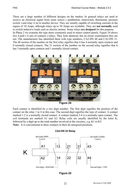
In Phase 2 we examine the type more commonly used in motor control panels. Figure 24 shows<br />
two 4 pole ( 4 sets <strong>of</strong> contacts ) relays. They look identical, but on closer examination they are<br />
not. The manufacturer has identified them with type numbers, CA2-DN 40 and CA2-DN 31.<br />
The 40 section <strong>of</strong> the number on the first relay signifies that it has 4 normally open contacts and<br />
0 normally closed contacts. The 31 section <strong>of</strong> the number on the second relay signifies that it<br />
has 3 normally open contacts and 1 normally closed contact.<br />
Figure 24<br />
Each contact is identified by a two digit number. The first digit signifies the position <strong>of</strong> the<br />
contact on the relay 1 to 4 in this case. The second digit signifies the type <strong>of</strong> contact. A contact<br />
marked 1-2 is a normally closed contact. A contact marked 3-4 is a normally open contact. The<br />
coil terminals are marked A1 and A2. Relay coils are usually identified by the letter K,<br />
followed by a digit up to the total number involved in the circuitry, e.g. K1 to K5.<br />
Note: It is conventional to draw contacts in their de-energised positions.<br />
CA2-DN 22 Relay<br />
Figure 25<br />
22<br />
Revision 4. Feb 2009