Trade of Electrician Motor Control COURSE NOTES - eCollege
Trade of Electrician Motor Control COURSE NOTES - eCollege
Trade of Electrician Motor Control COURSE NOTES - eCollege

You also want an ePaper? Increase the reach of your titles
YUMPU automatically turns print PDFs into web optimized ePapers that Google loves.
FAS Electrical Course Notes – Module 2.4.2<br />
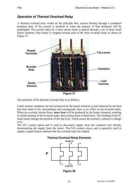
Operation <strong>of</strong> Thermal Overload Relay<br />
A thermal overload relay works on the principle that, current flowing through a conductor<br />
produces heat. If the current is doubled in value the amount <strong>of</strong> heat produced will be<br />
quadrupled. The current taken by a three phase motor is passed through a set <strong>of</strong> three small<br />
heater elements. One heater is wrapped around each <strong>of</strong> the three bi-metal strips as shown in<br />
Figure 37.<br />
Supply<br />
Terminals<br />
Bi-metal<br />
Strip<br />
Heater<br />
Element<br />
Figure 37<br />
The operation <strong>of</strong> the thermal overload relay is as follows:<br />
Under normal conditions the heat produced by the heater elements is just balanced by the heat<br />
lost from them to the surroundings and consequently there is no effect on the bi-metal strips.<br />
When an overload current flows, more heat will be produced by the heater elements, resulting<br />
in further heating <strong>of</strong> the bi-metal strips, thus causing them to bend more. This bending <strong>of</strong> the bimetal<br />
strips changes the position <strong>of</strong> the trip lever, which causes the auxiliary contacts to change<br />
over.<br />
The N/C contact opens and is used to disconnect supply from the contactor coil, thereby<br />
disconnecting the supply from the motor. The N/O contact closes and is generally used to<br />
supply a signal lamp to indicate that the overload relay has tripped.<br />
Thermal Overload Relay Elements<br />
F<br />
1<br />
Supply in<br />
3 5<br />
2 4 6<br />
Load out<br />
Figure 38<br />
31<br />
Trip Levers<br />
Insulation<br />
Load<br />
Terminal<br />
Revision 4. Feb 2009