Volume Control Instructions - EMG Pickups
Volume Control Instructions - EMG Pickups
Volume Control Instructions - EMG Pickups

You also want an ePaper? Increase the reach of your titles
YUMPU automatically turns print PDFs into web optimized ePapers that Google loves.
0230-0161A<br />
PO BOX 4394<br />
SANTA ROSA, CA<br />
95402 USA<br />
P (707) 525-9941<br />
F (707) 575-7046<br />
<strong>EMG</strong>PICKUPS.COM<br />
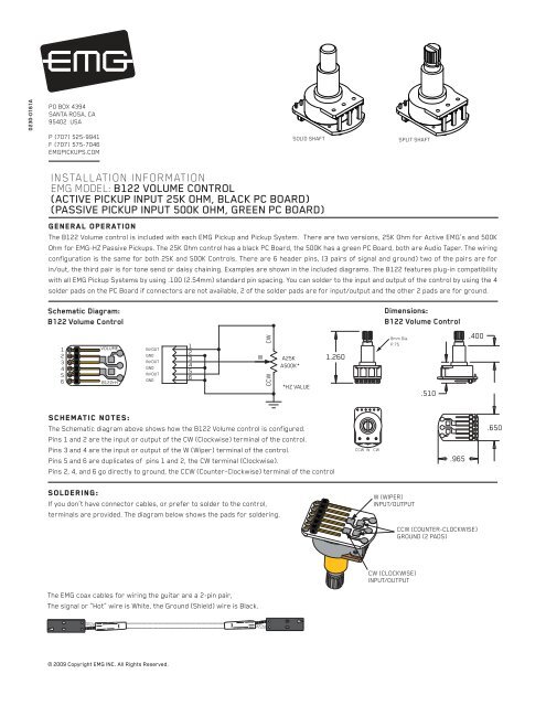
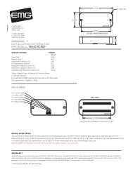
INSTALLATION INFORMATION<br />
<strong>EMG</strong> MODEL: B122 VOLUME CONTROL<br />
(ACTIVE PICKUP INPUT 25K OHM, BLACK PC BOARD)<br />
(PASSIVE PICKUP INPUT 500K OHM, GREEN PC BOARD)<br />
SCHEMATIC NOTES:<br />
The Schematic diagram above shows how the B122 <strong>Volume</strong> control is configured.<br />
Pins 1 and 2 are the input or output of the CW (Clockwise) terminal of the control.<br />
Pins 3 and 4 are the input or output of the W (Wiper) terminal of the control.<br />
Pins 5 and 6 are duplicates of pins 1 and 2, the CW terminal (Clockwise).<br />
Pins 2, 4, and 6 go directly to ground, the CCW (Counter-Clockwise) terminal of the control<br />
SOLID SHAFT SPLIT SHAFT<br />
General Operation<br />
The B122 <strong>Volume</strong> control is included with each <strong>EMG</strong> Pickup and Pickup System. There are two versions, 25K Ohm for Active <strong>EMG</strong>’s and 500K<br />
Ohm for <strong>EMG</strong>-HZ Passive <strong>Pickups</strong>. The 25K Ohm control has a black PC Board, the 500K has a green PC Board, both are Audio Taper. The wiring<br />
configuration is the same for both 25K and 500K <strong>Control</strong>s. There are 6 header pins, (3 pairs of signal and ground) two of the pairs are for<br />
in/out, the third pair is for tone send or daisy chaining. Examples are shown in the included diagrams. The B122 features plug-in compatibility<br />
with all <strong>EMG</strong> Pickup Systems by using .100 (2.54mm) standard pin spacing. You can solder to the input and output of the control by using the 4<br />
solder pads on the PC Board if connectors are not available, 2 of the solder pads are for input/output and the other 2 pads are for ground.<br />
Schematic Diagram:<br />
B122 <strong>Volume</strong> <strong>Control</strong><br />
1<br />
2<br />
3<br />
4<br />
5<br />
6<br />
VOLUME<br />
B122rH<br />
IN/OUT<br />
GND<br />
IN/OUT<br />
GND<br />
IN/OUT<br />
GND<br />
SOLDERING:<br />
If you don’t have connector cables, or prefer to solder to the control,<br />
terminals are provided. The diagram below shows the pads for soldering.<br />
The <strong>EMG</strong> coax cables for wiring the guitar are a 2-pin pair,<br />
The signal or “Hot” wire is White, the Ground (Shield) wire is Black.<br />
© 2009 Copyright <strong>EMG</strong> INC. All Rights Reserved.<br />
1<br />
2<br />
3<br />
4<br />
5<br />
6<br />
W<br />
CW<br />
CCW<br />
A25K<br />
A500K*<br />
*HZ VALUE<br />
1.260<br />
CCW W CW<br />
Dimensions:<br />
B122 <strong>Volume</strong> <strong>Control</strong><br />
8mm Dia.<br />
P.75<br />
W (WIPER)<br />
INPUT/OUTPUT<br />
CW (CLOCKWISE)<br />
INPUT/OUTPUT<br />
.510<br />
.965<br />
.400<br />
CCW (COUNTER-CLOCKWISE)<br />
GROUND (2 PADS)<br />
.650
Diagram NOTES:<br />
Diagrams #1 and #2 perform the same function.<br />
Diagram #1 shows the pickup input going into the CW pair (pins 1 and 2).<br />
Diagram #2 shows the pickup input going to the CW pair (pins 5 and 6).<br />
Again, pairs 1-2 and 5-6 are interchangeable, both are the CW pair.<br />
Both diagrams show the output coming from the W pair (pins 3 and 4).<br />
Instruments with one pickup:<br />
It is recommended plugging the pickup onto either CW pair (pins 1-2 or 5-6) and taking the output of the <strong>Volume</strong> control from the W pair (pins 3-4)<br />
as in Diagram #1 or #2.<br />
Master <strong>Volume</strong> with 2 pickups and a selection switch:<br />
If you wish master volume control when the selection switch is in the “both” position, input the pickups onto either CW (Clockwise) pair (pins 1-2 or 5-6)<br />
and take the output from the W (Wiper) Pair, pins 3-4, as in Diagrams #1 or #2<br />
Diagram #1<br />
Pickup input on pins 1 and 2 (CW Terminal)<br />
Output on pins 3 and 4 (W Terminal)<br />
FROM PICKUP<br />
Independent <strong>Volume</strong> with 2 pickups and a selection switch:<br />
If you wish independent volume control when the selection switch is in the “both” position, input the pickups to the W (Wiper) pair (pins 3-4) and take<br />
the output from either CW pair (pins 1-2 or 5-6) as in Diagrams #3 or #4.<br />
Sending the pickup input to the wiper (W Terminal) is common in installations that have two pickups but no selection switch, it allows the volume control<br />
of each pickup to work indpendent of the other. A <strong>Volume</strong>/<strong>Volume</strong>/Master Tone setup is a perfect example of this. If you have a selection switch, using<br />
the W pair (pins 3 and 4) allows each volume control to work independently in the “both” pickup switch position.<br />
Diagram #3<br />
Pickup in on pins 3 and 4 (W Terminal)<br />
Output on pins 5 and 6 (CW Terminal)<br />
FROM PICKUP<br />
B122 Page 2<br />
MASTER<br />
VOLUME<br />
NECK PICKUP<br />
BRIDGE PICKUP<br />
OUTPUT<br />
VOLUME<br />
OUTPUT<br />
VOLUME<br />
6<br />
5<br />
4<br />
3<br />
2<br />
1<br />
6<br />
5<br />
4<br />
3<br />
2<br />
1<br />
NECK<br />
VOLUME<br />
Diagram #2<br />
Pickup input on pins 5 and 6 (CW Terminal)<br />
Output on pins 3 and 4 (W Terminal)<br />
FROM PICKUP<br />
Diagram #4<br />
Pickup in on pins 3 and 4 (W Terminal)<br />
Output on pins 1 and 2 (CW Terminal)<br />
FROM PICKUP<br />
OUTPUT<br />
BRIDGE<br />
VOLUME<br />
VOLUME<br />
OUTPUT<br />
VOLUME<br />
Independent volume with 2 pickups and no selection switch:<br />
Sending the pickup input to the wiper (W Terminal) is common in installations that have 2 pickups but no selection switch. This allows the volume<br />
control of each pickup to work independent of the other. A <strong>Volume</strong>/<strong>Volume</strong>/Master Tone setup is a perfect example of this. Pickup input to the<br />
W pair (pins 3 and 4) allows each volume control to work independently.<br />
6<br />
5<br />
4<br />
3<br />
2<br />
1<br />
6<br />
5<br />
4<br />
3<br />
2<br />
1<br />
OUTPUT<br />
6<br />
5<br />
4<br />
3<br />
2<br />
1<br />
6<br />
5<br />
4<br />
3<br />
2<br />
1

![Product Data Sheet [pdf] - Electric Guitar Pickups](https://img.yumpu.com/7633239/1/190x245/product-data-sheet-pdf-electric-guitar-pickups.jpg?quality=85)
![HZ 35 40 45 INST_B [Converted].ai - EMG Pickups](https://img.yumpu.com/5350888/1/190x146/hz-35-40-45-inst-b-convertedai-emg-pickups.jpg?quality=85)
![Product Data Sheet [pdf] - EMG Pickups](https://img.yumpu.com/5350725/1/158x260/product-data-sheet-pdf-emg-pickups.jpg?quality=85)
![Product Data Sheet [pdf] - EMG Pickups](https://img.yumpu.com/5350674/1/174x260/product-data-sheet-pdf-emg-pickups.jpg?quality=85)