![Product Data Sheet [pdf] - Electric Guitar Pickups](https://img.yumpu.com/7633239/1/500x640/product-data-sheet-pdf-electric-guitar-pickups.jpg)
Product Data Sheet [pdf] - Electric Guitar Pickups
Product Data Sheet [pdf] - Electric Guitar Pickups
Product Data Sheet [pdf] - Electric Guitar Pickups

Create successful ePaper yourself
Turn your PDF publications into a flip-book with our unique Google optimized e-Paper software.
0230-0202J<br />
PO BOX 4394<br />
SANTA ROSA, CA<br />
95402 USA<br />
P (707) 525-9941<br />
F (707) 575-7046<br />
EMGPICKUPS.COM<br />
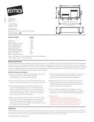
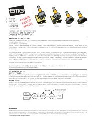
INSTALLATION INFORMATION<br />
EMG MODEL: BQS CONTROL<br />
(ACTIVE / PASSIVE PICKUP INPUT)<br />
.650<br />
(16.5)<br />
2.200<br />
(55.8)<br />
BASS<br />
CONTROL<br />
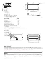
SPECIFICATIONS<br />
Input Impedance (Ohms) 500K Ohm<br />
Gain/Attenuation/ Frequency Bass Control +/-12db/20Hz<br />
Gain/Attenuation/ Frequency Treble Control +/-12db/(Adjustable)<br />
Input Referred Noise -120dbV<br />
Output Impedance (Ohms) 2K<br />
Recommended Supply Voltage 18 Volts<br />
Current @ 9V/18V (Microamps) 600/740<br />
Battery Life (Hours) 750<br />
Maximum Supply (Volts DC) 27 Volts<br />
Dimensions:<br />
BQS (Mid/Bass/Treble)<br />
Equalizer<br />
BASS<br />
CONTROL<br />
TREBLE<br />
CONTROL<br />
TREBLE<br />
CONTROL<br />
BASS<br />
CONTROL<br />
TREBLE<br />
CONTROL<br />
MID-RANGE<br />
CONTROL<br />
INCLUDED:<br />
1 BQS Control<br />
4 Knobs<br />
1 Battery Clip with Buss Connector<br />
1 Stereo Output Jack (Battery Switching)<br />
4 Interconnect Cables (2 Red, 2 White)<br />
General Operation<br />
The BQS System is an active EQ circuit for bass guitars. Their effects are illustrated in the graphs on the next page. They allow you separate<br />
control over bass, midrange, and treble. Rotate the controlled clockwise to boost, counterclockwise to cut. There is a center detent for flat<br />
response. Active or Passive pickups can be used with the BQC and BQS Controls.<br />
The mid-range control has a variable frequency knob that allows you to sweep through the mid-frequency range from 100Hz to 1KHz. This<br />
selects the frequency to boost or cut. The graphs on page 2 depict the frequency response of the controls.<br />
Battery Power:<br />
If you play the instrument very hard, and are boosting the bass or treble with the BQS, you should consider operating the instrument on +18<br />
Volts (See “Power Tips” under Accessories/product data sheets at http://www.emgpickups.com). If you play mildly and use a minimum of boost<br />
the instrument should operate easily on a single 9-Volt battery. Use an Alkaline or Lithium battery for the best battery life and always unplug<br />
your guitar when you’re not using it.<br />
2.700<br />
(68.5)<br />
6mm<br />
D Shaft<br />
8mm<br />
P .75<br />
Warranty<br />
All EMG <strong>Pickups</strong> and accessories are warranted for a period of two years. This warranty does not cover failure due to improper installation, abuse or damage. If<br />
upon examination the pickup is determined to be defective, a replacement will be made. Warranty replacement products are covered by this same warranty. This<br />
warranty covers only those pickups and accessories sold by authorized EMG Dealers. This warranty is not transferable.<br />
© 2011 Copyright EMG INC. All Rights Reserved.<br />
9mm<br />
P .075<br />
.880<br />
(22.4)<br />
1.945<br />
(49)
Installation Instructions:<br />
EMG Model: BQS Control<br />
High Frequency (Treble) Response Selection:<br />
The BQC has the added feature of allowing you to choose from 4 different<br />
high frequency response curves. This is a nice feature especially if you are<br />
using the BQC with passive pickups. The following diagrams show the dip-switch<br />
positions and the graphs show the resultant frequency response.<br />
The BQC Control is an equalizer style control, offering both boost and cut<br />
at the same frequency locations. The control also features a center detent<br />
(click) that lets you know when no equalization is in effect.<br />
10 dB/div<br />
20Hz<br />
10 dB/div<br />
20Hz<br />
ON/ON<br />
BQC CONTROL (TREBLE RESPONSE: ON/ON)<br />
OFF/OFF<br />
1KHz<br />
BQC CONTROL (TREBLE RESPONSE: 1 OFF/2 OFF)<br />
1KHz<br />
Low Frequency (Bass) Response:<br />
The BQC has a fairly standard bass response boost and cut. It’s slope is<br />
6dB per octave and is centered at 50Hz. As you can see in the graph<br />
on the left the signal can be boosted by +12db (Red Line) or cut by<br />
-12dB (Green Line). A center detent (click) is provided on the control<br />
to let you know when the frequency response is flat or unaffected<br />
by boosting or cutting.<br />
BQS Control Page 2<br />
MID BOOST OR CUT (UPPER CONTROL)<br />
MID FREQUENCY SELECTION (LOWER CONTROL)<br />
10KHz<br />
10KHz<br />
10 dB/div<br />
20Hz<br />
10 dB/div<br />
20Hz<br />
10 dB/div<br />
20Hz<br />
10 dB/div<br />
20Hz<br />
OFF/ON<br />
BQC CONTROL (TREBLE RESPONSE: 1 OFF/2 ON)<br />
ON/OFF<br />
1KHz<br />
BQC CONTROL (TREBLE RESPONSE: 1 ON/2 OFF)<br />
1KHz<br />
BQC CONTROL BASS RESPONSE<br />
1KHz<br />
VARIABLE MID-RANGE FREQUENCY<br />
100Hz<br />
TREBLE BOOST OR CUT (UPPER CONTROL)<br />
BASS BOOST OR CUT (LOWER CONTROL)<br />
BASS/TREBLE<br />
CONTROL<br />
1.0KHz<br />
1KHz<br />
10KHz<br />
10KHz<br />
10KHz<br />
Mid-Range Frequency Response:<br />
One of the primary features of the BQC is it’s mid-range control. It allows you to<br />
choose the frequency you want to boost or cut from 100 to 1000 Hz. The concentric<br />
mid-range pot has two sections. The lower control chooses the frequency, while the<br />
upper control lets you choose the amount of boost or cut you want. The maximum slope<br />
is 12dB per octave at full gain or cut.. There is also a center detent (click) in the center<br />
of the upper control to let you know when the control is not having any effect.<br />
10KHz
The BQS Control is easily installed by using the connector cables supplied.<br />
Diagram #1 shows the cables connected to the BQS Control. This 5-pin<br />
layout is the same for all EMG Accessories, so they can be interchanged.<br />
There are a variety of ways instruments can be wired. The examples shown<br />
here are only a few. If your instrument has different wiring than shown here<br />
go to our website: http://www.emgpickups.com for alternate diagrams.<br />
Diagram #2 below shows the installation of a single Volume control along with<br />
the BQS Control.<br />
Diagram #2<br />
Master Volume<br />
BQS Control<br />
BRIDGE PICKUP<br />
NECK PICKUP<br />
BASS<br />
CONTROL<br />
Installation Instructions:<br />
EMG Model: BQS Control<br />
- 9V +<br />
VOLUME<br />
NOTE:<br />
REVERSED<br />
CONNECTOR<br />
- 9V +<br />
NECK<br />
VOLUME<br />
BATTERY<br />
BUSS<br />
BQC<br />
CONTROL<br />
2 <strong>Pickups</strong>, 2 Volume controls, BQS Control, no selection switch<br />
J-Bass Style wiring<br />
Refer to Diagram #3<br />
1) Install the <strong>Pickups</strong> and route the Pickup cables to the control cavity.<br />
If the cables are too long, keep any excess under the pickup.<br />
2) Mount the Volume and Tone controls into the body / pickguard.<br />
Plug the Neck Pickup Cable onto the Neck Volume control.<br />
Plug the Bridge Pickup Cable onto the Bridge Volume control.<br />
3) Plug a coax cable from the Neck Volume control to the Bridge Volume<br />
control.<br />
4) Plug a coax cable from the Bridge Volume control to the BQS Control.<br />
Diagram #3<br />
Volume / Volume<br />
BQS Control<br />
BQS Control Page 3<br />
OUTPUT CABLE<br />
BASS<br />
CONTROL<br />
BRIDGE<br />
VOLUME<br />
S<br />
TREBLE<br />
CONTROL<br />
R<br />
T<br />
OUTPUT<br />
Diagram #1<br />
NOTE:<br />
REVERSED INPUT<br />
CONNECTOR<br />
BATTERY<br />
BUSS<br />
RED TO 9V + BUSS<br />
OUTPUT TO JACK<br />
INPUT<br />
5) Plug the output cable from the BQS Control and connect the output<br />
wires to the output jack by pushing the connectors on as shown.<br />
WHITE wire onto the TIP (T) contact,<br />
BLACK wire onto the SLEEVE (S) contact<br />
BLACK Battery Negative wire onto the RING (R) contact.<br />
6) Plug the RED Wires of the pickups onto the V+ Supply Buss (RED Shroud)<br />
along with the RED of the battery clip.<br />
Extra pins on the V+ Supply Buss are for EMG Accessories.<br />
7) Put the battery in the insulating foam piece provided and place it securely<br />
in the control cavity.<br />
We suggest that you plug in the instrument and test it before closing the<br />
control cavity.<br />
OUTPUT CABLE<br />
TREBLE<br />
CONTROL<br />
NOTE:<br />
REVERSED<br />
CONNECTOR<br />
BQC<br />
CONTROL<br />
BASS<br />
S<br />
OUTPUT<br />
R<br />
T
Installation (Two Pickup <strong>Guitar</strong>s with Selection switch):<br />
<strong>Guitar</strong>s with two pickups and a selection switch will use the EMG B157 Pickup Buss<br />
shown at the right in Diagram #4a.<br />
The Pickup Buss is a convenient way to wire your guitar without soldering.<br />
There is a separate sheet attached to these instructions that describes the<br />
Pickup Buss in detail.<br />
In all installations it’s best to find a place to mount the Pickup Buss in the control<br />
cavity before starting. Then, after the cables are routed use the velcro to mount it<br />
securely.<br />
2 <strong>Pickups</strong> / Toggle Select Switch / Master Volume and BQS Control<br />
1) Install the <strong>Pickups</strong> and route the Pickup cables to the control cavity.<br />
If the cables are too long, wind up the excess and keep it under the pickup.<br />
2) Mount the Volume and Tone controls into the body.<br />
Plug both Pickup cables into the Pickup Buss (BLACK Shroud) as shown,<br />
Refer to Diagram #4a<br />
Bridge Pickup to Position 1<br />
Neck Pickup to Position 2.<br />
3) Plug a coax cable from the Pickup Buss (Position 3) to the Master Tone (Active)<br />
as shown in Diagram #4b. Note the reversed connector on pins 1 and 2.<br />
4) Plug a coax cable from the Master Tone (ACTIVE) to the Master Volume as shown.<br />
5) Strip the insulation from the switch wires and Insert them into the GREEN<br />
Terminal Block and tighten the screws with a small screwdriver.<br />
The Bridge pickup goes to the BR Terminal<br />
The Neck pickup goes to the NK Terminal<br />
The Output of the switch goes to the O Terminal<br />
If there is a ground wire coming from the switch, insert it into one of the black<br />
terminals on the terminal block.<br />
Diagram #4b<br />
2 <strong>Pickups</strong><br />
Toggle Style Select Switch<br />
Master Volume & Master Tone<br />
BQS Control Page 4<br />
Diagram #5<br />
ABC / Master Volume<br />
BQS Control<br />
Output Jack<br />
EMG Active Neck Pickup<br />
(Upper 3 pin header)<br />
EMG Active Bridge Pickup<br />
(Lower 3 pin header)<br />
GROUND<br />
NECK P/U<br />
OUTPUT<br />
BRIDGE P/U<br />
RED WIRES<br />
FROM PICKUPS<br />
- 9V +<br />
FROM NECK PICKUP<br />
FROM BRIDGE PICKUP<br />
- 9V +<br />
B118<br />
ACTIVE BALANCE<br />
CONTROL<br />
RED<br />
BATTERY<br />
NEG (-)<br />
RED<br />
RED<br />
RED<br />
RED<br />
BASS<br />
CONTROL<br />
Diagram #4a<br />
BRIDGE PICKUP<br />
NECK PICKUP<br />
MASTER<br />
VOLUME<br />
TREBLE<br />
CONTROL<br />
RED<br />
BASS<br />
CONTROL<br />
9V+ POWER BUSS<br />
NOTE:<br />
REVERSED<br />
CONNECTOR<br />
BRIDGE PICKUP (POSITION 1)<br />
NECK PICKUP (POSITION 2)<br />
OUTPUT (POSITION 3)<br />
OUTPUT TO MASTER TONE<br />
6) Plug the output cable onto the Master Volume control and connect the output<br />
wires to the output jack and push the connectors onto the jack as shown.<br />
WHITE wire onto the TIP (T) contact,<br />
BLACK wire onto the SLEEVE (S) contact<br />
BLACK Battery Negative wire onto the RING (R) contact.<br />
7) Plug the RED Wires of the pickups onto the V+ Supply Buss (RED Shroud)<br />
along with the RED of the battery clip, and the RED wire of the Active Tone Control.<br />
Extra pins on the V+ Supply Buss are for EMG Accessories.<br />
8) Put the battery in the insulating foam piece provided and place it securely in the<br />
control cavity.<br />
We suggest that you plug in the instrument and test it before closing the<br />
control cavity.<br />
BQS<br />
CONTROL<br />
MASTER<br />
VOLUME<br />
BATTERY<br />
NEG (-) BLACK<br />
OUTPUT CABLE<br />
BQS<br />
CONTROL<br />
OUTPUT CABLE<br />
NOTE:<br />
REVERSED<br />
CONNECTOR<br />
TREBLE<br />
CONTROL<br />
S<br />
S<br />
OUTPUT<br />
R<br />
T<br />
OUTPUT<br />
R<br />
T<br />
BOTTOM<br />
VIEW

![HZ 35 40 45 INST_B [Converted].ai - EMG Pickups](https://img.yumpu.com/5350888/1/190x146/hz-35-40-45-inst-b-convertedai-emg-pickups.jpg?quality=85)
![Product Data Sheet [pdf] - EMG Pickups](https://img.yumpu.com/5350725/1/158x260/product-data-sheet-pdf-emg-pickups.jpg?quality=85)
![Product Data Sheet [pdf] - EMG Pickups](https://img.yumpu.com/5350674/1/174x260/product-data-sheet-pdf-emg-pickups.jpg?quality=85)