TRADE OF VEHICLE BODY REPAIR - eCollege
TRADE OF VEHICLE BODY REPAIR - eCollege
TRADE OF VEHICLE BODY REPAIR - eCollege

Create successful ePaper yourself
Turn your PDF publications into a flip-book with our unique Google optimized e-Paper software.
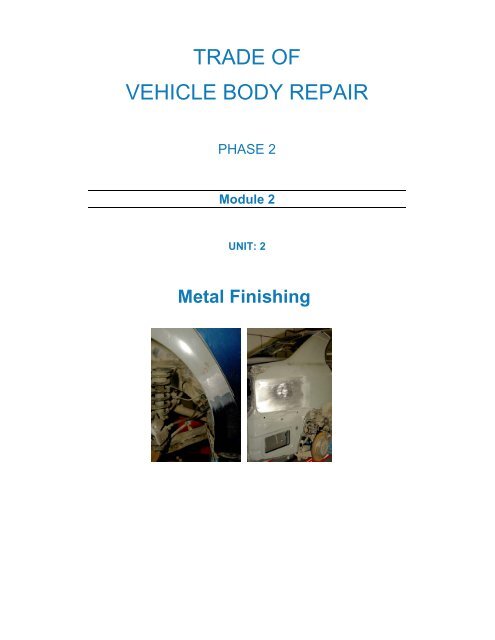
<strong>TRADE</strong> <strong>OF</strong><br />
<strong>VEHICLE</strong> <strong>BODY</strong> <strong>REPAIR</strong><br />
PHASE 2<br />
Module 2<br />
UNIT: 2<br />
Metal Finishing
Produced by FÁS Learning Innovation Unit<br />
In co-operation with<br />
Subject Matter Experts:<br />
Maurice Stack<br />
&<br />
CDX Global<br />
FENC – Further Education National Consortium<br />
© Foras Áiseanna Saothair 2006
Table of Contents<br />
Metal Finishing.............................................................................................................. 1<br />
Learning Outcome:.......................................................................................................1<br />
Exercise – Metal Finishing...........................................................................................2<br />
Introduction.................................................................................................................... 3<br />
Metal Finishing..............................................................................................................3<br />
Metal Finishing Safety ................................................................................................. 5<br />
Shaping Metal by Hand............................................................................................... 6<br />
Hollowing.......................................................................................................................7<br />
Raising ............................................................................................................................8<br />
Wheeling.......................................................................................................................10<br />
Split-and-Weld System of Shaping Metal ................................................................13<br />
Damage Assessment................................................................................................... 14<br />
Preparing the Panel for Repair ................................................................................ 17<br />
Removal of Under-body Coatings............................................................................17<br />
Roughing Out Damage ..............................................................................................18<br />
Planishing.....................................................................................................................19<br />
Hammering Techniques........................................................................................... 22<br />
Direct Hammering......................................................................................................23<br />
Indirect Hammering (off the dolly block) ...............................................................25<br />
Spring Hammering......................................................................................................26<br />
Removing Low Spots .................................................................................................27<br />
Filing Techniques ....................................................................................................... 29<br />
Filing .............................................................................................................................29<br />
Grinding Techniques..................................................................................................31<br />
Summary........................................................................................................................ 32
Self Assessment............................................................................................................ 33<br />
Questions – Module 2. Unit 2...................................................................................33<br />
Answers to Questions 1-10. Module 2. Unit 2 .......................................................35
Table of Figures<br />
Figure 1: Grinding/Filing a Door Panel...................................................................... 5<br />
Figure 2: Shaping Metal by Hand................................................................................. 6<br />
Figure 3: Technique of Hollowing ............................................................................... 8<br />
Figure 4: Raising ............................................................................................................. 9<br />
Figure 5: Wheeling Machine........................................................................................ 12<br />
Figure 6: Split-and-Weld Pattern................................................................................ 13<br />
Figure 7: Grain Structure............................................................................................. 14<br />
Figure 8: Change in Grain Structure during Pressing.............................................. 14<br />
Figure 9: Pressed wing panel....................................................................................... 15<br />
Figure 10: High/Low Crown ...................................................................................... 16<br />
Figure 11: Roughing out Damage............................................................................... 18<br />
Figure 12: Positioning of Blows in the Roughing-out Technique.......................... 18<br />
Figure 13: Planishing using a Hammer and Dolly.................................................... 20<br />
Figure 14: Planishing using a Wheeling Machine ..................................................... 20<br />
Figure 15: Planishing using a Steel Stake ................................................................... 21<br />
Figure 16: Swing of the Planishing Hammer............................................................. 22<br />
Figure 17: Hammer and Dolly in use......................................................................... 23<br />
Figure 18: Direct Hammering ..................................................................................... 23<br />
Figure 19: The Technique of Direct Hammering..................................................... 24<br />
Figure 20: Using a High-crowned dolly..................................................................... 24<br />
Figure 21: Using a Low-crowned Dolly..................................................................... 25<br />
Figure 22: The Technique of Spring Hammering.................................................... 26<br />
Figure 23: The Technique of Spring Hammering.................................................... 27<br />
Figure 24: Pick Hammering used to remove Low Spots ........................................ 28
Figure 25: Removes High and Low Spots on Metal Surface.................................. 29<br />
Figure 26: Filing a Door Panel.................................................................................... 30<br />
Figure 27: Cross Filing at 45º...................................................................................... 30<br />
Figure 28: Cross Filing at 90º...................................................................................... 31
Module 2– Unit 2<br />
Metal Finishing<br />
Learning Outcome:<br />
By the end of this unit each apprentice will be able to:<br />
• State the hazards that can be created by sharp edges, metal<br />
filings and sparks<br />
• Determine the extent of damage to a panel<br />
• Select the correct tools including dolly curvature<br />
• Prepare the panel for repair<br />
• Identify the plastic and elastic regions<br />
• Apply corrective forces to restore the contour of the panel<br />
• Metal finish the panel<br />
• Restore the correct tension to the panel<br />
Key Learning points<br />
• Safety sharp edges, metal filings and sparks<br />
• Damage assessment<br />
• Plastic and elastic regions<br />
• Roughing out<br />
• Hammering techniques<br />
• Filing techniques<br />
• Grinding technique<br />
• Methods of assessing surface contour quality<br />
• Removal of under-body coatings<br />
Training Resources<br />
• Classroom/workshop<br />
• Tool kit grinder and discs<br />
• Damaged body panel<br />
• Personal protection equipment<br />
Suggested Exercises<br />
Determine the extent of damage, rough out and metal finish, a<br />
damaged high crown section of body panel and finish to an<br />
acceptable quality standard suitable for refinishing<br />
Vehicle Body Repairs - Phase 2 1
Module 2– Unit 2<br />
Exercise – Metal Finishing<br />
Instructions:<br />
• Assess by sight and touch, minor damage to vehicle body<br />
panel<br />
• Select and use correctly and safely the correct tools<br />
• Metal finish minor damage to vehicle body panel<br />
Tools and Materials:<br />
• Safety Equipment<br />
• A range of panel beating dollies, hammers and bumping files<br />
• Grinders and discs<br />
• Damaged vehicle body panel<br />
• Personal Protection Equipment (see Induction)<br />
Dimensions Gen. tol. Scale Material<br />
mm nts<br />
METAL FINISH<br />
FAS Phase 2. Mod 2. Practice<br />
Standards: Re-shaping carried out with minimum distortion.<br />
Hammering techniques carried out correctly. Original contour<br />
achieved. Repairs free from file disc or burn marks.<br />
Vehicle Body Repairs - Phase 2 2
Module 2– Unit 2<br />
Introduction<br />
Metal Finishing<br />
Filing is a means of metal finishing a damaged panel prior to<br />
sanding operations for paint spraying. Essentially, panel beating is a<br />
hand method of producing hollow or double-curvature shapes by<br />
means of hammering and metal finishing nevertheless the panel<br />
beater’s craft still retains its place in body work and as yet is<br />
irreplaceable by more modern methods, in spite of the tremendous<br />
developments in recent years of mechanical methods of forming,<br />
panel beating remains as essential means of fabrication of special<br />
parts. Some metal shapes cannot be produced at all by mechanical<br />
methods and others only with great difficulty and in such cases<br />
panel beating is used to finish the shape that has been rouged out<br />
by power processes. Often, too, the prototype of a component<br />
ultimately to be made in quantity by stamping or pressing is hand<br />
made to allow minor modifications to be studied before mechanical<br />
production begins, the part produced by panel beating is used as the<br />
pattern for press or stamp tools. Panel beating may also be used<br />
where a small number of components only are required and where<br />
the cost of press or stamp tools would be uneconomic. In body<br />
repair work, panel beating is used to advantage where sections<br />
which are either unobtainable or uneconomical to replace<br />
completely can be fabricated by hand either in part or as a whole. In<br />
many cases corroded areas can be repaired by fabricating new<br />
sections for replacement purposes. In the body building trade, panel<br />
beating is still used to large extent where new vehicles are built<br />
either in aluminium or mild steel. Many of the components for<br />
these vehicles are still made using the traditional hand shaping<br />
methods. Also a lot of the aluminium moulds used in fibreglass<br />
construction, where highly developed double-curvature shapes are<br />
needed, are made by hand, welded and dressed, planishied or<br />
wheeled to a final finish.<br />
Panel beating is essentially a hammering process, involving different<br />
kinds of blows that can be struck on sheet metal. It should be borne<br />
in mind that most metals used in body work possess high<br />
malleability and may be overstretched even with a wood tool. The<br />
three types of blow that can be struck on sheet metal are:<br />
Solid Blow Where the work is struck solidly over a steel stake.<br />
Elastic Blow where either the head or the toll or both is made of a<br />
resilient material such as wood.<br />
Vehicle Body Repairs - Phase 2 3
Module 2– Unit 2<br />
Floating Blow where the stake is not directly under the hammer.<br />
Each type of blow has its uses for<br />
particular purposes. A solid blow will<br />
stretch the sheet and may be necessary<br />
when forming a panel, bending a<br />
curved strip or angle, removing a loose<br />
or tight place in a sheet, or throwing an<br />
edge over when thickness is not a<br />
consideration. An elastic blow will form<br />
metal without undue stretching, indeed<br />
metal can be thickened if desired, as in<br />
working out a tuck or pucker. The<br />
floating blow is given to the metal when<br />
it is held over a suitable head and hit<br />
‘off the solid’, so forming dents at the<br />
point of impact.<br />
Vehicle Body Repairs - Phase 2 4
Module 2– Unit 2<br />
Metal Finishing Safety<br />
When filing metal panels care should be taken with the edges of the<br />
panels as they become very shape from the filing. Always use gloves<br />
and goggles to protect your eyes from flying sparks and paint<br />
debris. Fireproof overalls, safety boots and ear muffs are also<br />
essential.<br />
Figure 1: Grinding/Filing a Door Panel<br />
Vehicle Body Repairs - Phase 2 5
Module 2– Unit 2<br />
Shaping Metal by Hand<br />
Thin-gauge mild steel and light aluminium sheet material up to<br />
1.2mm and in some cases even 1.6mm can be satisfactorily hand<br />
beaten by wood mallets into double curvature forms (Figure 2). The<br />
usual practice is to beat the metal in a suitable recess in a wood<br />
block or upon a sandbag, in what is known as the hollowing or<br />
blocking process. Alternatively, the metal can be hammered into a<br />
wood block hollowed out to the shape of the job.<br />
Another method is that of raising the<br />
metal by means of floating blows over<br />
steel stakes or wood formers. This<br />
raising process can be speeded up<br />
considerably by ‘taking in’ or making<br />
tucks at the edges of the metal. This<br />
method is generally called puckering and<br />
after being made each pucker must be<br />
eliminated by careful blows to drive the<br />
metal into itself, so thickening the work<br />
at the edges. Much greater advantage<br />
may be taken of puckering in aluminium<br />
alloy sheet than in most metals because<br />
of its malleability and ductility. The exact<br />
degree of shaping of the metal which is<br />
permissible depends upon the particular<br />
alloy being worked, its malleability and<br />
the ability of the craftsman.<br />
Figure 2: Shaping Metal by Hand<br />
Another method of shaping metal which<br />
can be used in conjunction with<br />
hollowing and raising is that of wheeling.<br />
A panel can either be wheeled from a flat sheet to the desired<br />
double-curvature shape, or it can be pre-shaped using either<br />
hollowing or raising technique and its final shaping and smoothing<br />
completed by wheeling. The technique of wheeling is not entirely<br />
done by hand, as a wheeling machine is used. The finished result<br />
depends on the skill of the craftsman as he manipulates the sheet by<br />
hand in the wheeling machine.<br />
An experienced panel beater uses the beating method suitable to the<br />
job in hand, complex shapes often being beaten up by using both<br />
hollowing and raising or wheeling methods. For light-gauge material<br />
too much hollowing or blocking is not to be recommended, as it<br />
tends unduly to thin the metal. The skilled panel beater is a<br />
Vehicle Body Repairs - Phase 2 6
Module 2– Unit 2<br />
craftsman who, to a great extent, relies on a good eye for line and<br />
form, this can only be cultivated by years of experience which,<br />
combined with dexterity in the use of hand tools, is the secret of his<br />
craftsmanship. Wood formers or jigs, upon which the beaten shape<br />
can be tired in order to obtain uniformity of shape for each<br />
workpiece, are used for many jobs. The shape of the job is retained<br />
in the vision of the panel beater, who can, by beating on the<br />
sandbag and raising over a suitable stake, obtain a very good<br />
approximation to the desired form. This only needs hammering<br />
lightly on the wood former to obtain the finished shape. Until the<br />
metal fits the former it is often necessary to check repeatedly to find<br />
any high or low areas which may prevent the workpiece from fitting<br />
the former correctly. Instead of using formers or jigs many panel<br />
beaters use templates only, which are cut to the shape of the various<br />
cross-sections of the workpiece. These templates are used towards<br />
the end of the beating process to check the finished shape of the<br />
job. After shaping, the surface of the finished panel has to be<br />
smoothed by the technique of planishing, using a steel bench stake,<br />
or by wheeling.<br />
Hollowing<br />
One of the methods of shaping metal by hand is that of hollowing.<br />
In this method the metals used for the purpose of shaping panels<br />
for body work applications are usually aluminium and its alloys and<br />
mild steel, aluminium is by far the easier of the two to shape owing<br />
to its higher ductility and malleability properties. This is a process of<br />
shaping a sheet metal blank into a double-curvature shape by<br />
beating the blank into a sandbag or hard wood block with the aid of<br />
a pear-shaped boxwood mallet or for thin metal a rubber mallet, or<br />
for steel a hollowing hammer with a steel head.<br />
First the blank which is going to be shaped is cut to size and the<br />
edges trimmed for any rag by filing. If the rag is not removed and<br />
the blank is shaped, it may tend to split from the edge of the rag.<br />
The next step is to place the metal blank, which should be held<br />
tilted, on to a sandbag and to give it a series of blows around its<br />
outside edge, working towards the centre by means of a pearshaped<br />
mallet. This hammering has the effect of sinking the metal<br />
into the sandbag, which is of course resilient to the blows. After<br />
each blow the disc is turned and the next blow struck near the first<br />
one and so on until a series of lapping blows is made round the<br />
circumference of the blank. The tendency will be for creases or<br />
wrinkles to appear on the edges of the metal and these must be<br />
gently malleted flat to avoid overlapping of the metal and eventual<br />
cracking. The hammer of each course has to be done with steady<br />
and even blows to bring up a regular curved shape.<br />
Vehicle Body Repairs - Phase 2 7
Module 2– Unit 2<br />
On completion of the first course of blows, a second course is<br />
begun further in from the edge of the metal than the first set. This<br />
process of hammering in courses and rotating the blank is<br />
continued until eventually the centre of the blank is reached, by this<br />
time it will have taken on a double curvature shape, but should<br />
greater depth be required the whole operation must be started<br />
again, working gradually from the edge towards the centre of the<br />
work until it is completely to the desired shape and size.<br />
Figure 3: Technique of<br />
Hollowing<br />
At this stage templates cut to<br />
the correct size and shape can<br />
be used to check that the panel<br />
being shaped is the correct size<br />
and curvature. Alternatively it is<br />
possible to use a jig constructed<br />
to the correct size and shape,<br />
usually in wood. It may be<br />
necessary during the beating-up<br />
process to anneal the workpiece<br />
to restore its malleability, because the hammering tends to harden<br />
the metal by work hardening. In some cases, instead of using a<br />
sandbag for the shaping to be carried out on, a hollowed-out recess<br />
in a wood block can be used. When the panel has reached the<br />
desired shape by hollowing it can be smoothed to a final finish by<br />
hand planishing using a hand dolly or over a stake, or wheeling to<br />
obtain the final smoothness.<br />
Raising<br />
Raising is another method of shaping metal by hand into a doublecurvature<br />
shape. The method of raising is carried out by drawing<br />
the metal in courses over a suitably shaped steel stake or wood<br />
block, using floating blows which are struck slightly off the stake<br />
with a boxwood pear-shaped mallet. A series of blows is made in<br />
the metal starting at the centre, the blows being struck slightly off<br />
the stake. This has the effect of shrinking or reducing the<br />
circumference of the blank, thus forcing it down and around the<br />
stake. The disc or blank is rotated after each blow as in hollowing,<br />
but working from the centre in courses outwards towards the edges<br />
of the blank.<br />
Vehicle Body Repairs - Phase 2 8
Module 2– Unit 2<br />
The same process is repeated with frequent annealing of the metal<br />
until the final degree of raising is reached and the desired shape<br />
obtained. In the course of the raising, the edges of the metal around<br />
the circumference will be continually subjected to creasing, care and<br />
skill is needed to avoid allowing these creases to become to sharp. If<br />
they are not worked out the edge will crack or fracture as the shape<br />
proceeds. When the article is partly beaten up over the stake, a<br />
series of tucks can be made<br />
in the outer edges of the<br />
work in order to quicken up<br />
the beating or raising<br />
process by taking in or<br />
shrinking surplus metal.<br />
This method is to make a<br />
pucker or tuck at any point<br />
on the edge of the blank by<br />
bending the metal on a<br />
stake into an ear-shaped<br />
form.<br />
Figure 4: Raising<br />
After the tuck is formed, the disc is placed on a steel stake and each<br />
side of the tuck is lightly malleted to stiffen the metal and hold the<br />
tuck in position. This is done in three or four places on the<br />
circumference of the blank thus decreasing its diameter. Then<br />
working from the base or point of the tuck, this surplus metal is<br />
malleted out over a stake towards the edge of the disc. This has to<br />
be done vary carefully with the minimum of blows and overlapping<br />
must not take place. As each tuck is formed and worked out, the<br />
blank deepens towards its final shape.<br />
The processes of hollowing and raising in sheet metal are often<br />
applied together in the making of articles in the form of doublecurvature<br />
shapes, bowl-like shapes etc. when the work is only<br />
slightly domed, the process of hollowing alone may be sufficient to<br />
complete the work. There are limitations to the depth which can be<br />
obtained by hollowing. This is governed by the diameter of the<br />
finished article and access for hand tools. Where the diameter is<br />
going to be small and the article deep, the raising method will have<br />
to be used to shape the work. Again as in hollowing process, the<br />
final finish can be obtained by planishing the pre-shaped article to a<br />
smooth surface finish.<br />
Vehicle Body Repairs - Phase 2 9
Module 2– Unit 2<br />
Wheeling<br />
The craft of wheeling has been used for many years in the<br />
production of curved panel assemblies that are used to make up the<br />
modern vehicle body. Wheeling was a very skilled art when vehicles<br />
were coach built and hand methods were employed to make the<br />
component panels. With the advent of mass production and the<br />
development of the motor car, speed of production became an<br />
essential factor. Consequently hand-made panels, which were<br />
usually made by wheeling, were replaced by pressed panels made on<br />
power presses with mating dies, which very speedily produced<br />
accurate panels having a good surface finish. Today wheeling is still<br />
used to produce panels for prototype vehicles, one-off assemblies<br />
which are specially built to order and small volume production,<br />
where the panels pre-pressed to somewhere near the finished shape<br />
and finished off by wheeling. The vehicle building industry still uses<br />
wheeling in producing panels for commercial and private coaches,<br />
road transport vehicles and any assembly requiring a doublecurvature<br />
shape in its production.<br />
The art of wheeling lies in the operator’s ability to handle the panel<br />
successfully in the wheeling machine. Wheeling is simply the<br />
stretching of metal between two steel rolls known as wheels. The<br />
upper wheel has a flat face and revolves freely on its own bearing.<br />
The lower wheel also revolves but has a convex curved face which<br />
is pressed on to the top wheel. As the metal panel is pushed<br />
through the wheels a stretched area, the length of the panel is<br />
produced and is known as the wheel track. By carefully allowing<br />
these wheel tracks to overlap on the entire surface of the flat panel<br />
being wheeled, a curve in one direction only develops, to create<br />
double curvature on the same panel, stretching must take place in<br />
two opposing directions, therefore a second set of wheel tracks<br />
must cross the first set transversely and this is achieved by turning<br />
the panel through approximately 90º before making the second<br />
tracks. As the panel is pushed through the wheel pressure can be<br />
increased gradually until the desired curvature is obtained.<br />
Therefore the skill of wheeling lies in the use of correct wheel<br />
pressure and careful manipulation of the panel through the wheels<br />
this can only be learnt by experience. An alternative method of<br />
achieving double curvature on a flat panel is to form the first curve<br />
by using a rolling machine and then to wheel it in one direction<br />
only, allowing the tracks to cover the panel in the opposite direction<br />
to the first curve, thus stretching the metal in such a way to form<br />
the double curvature shape. Wheeling can therefore be used, first,<br />
for shaping a flat metal blank to a finished double-curved panel,<br />
second, to finish a pre-shaped panel which has been hollowed or<br />
raised to its final shape, and third, to smooth or planish a<br />
Vehicle Body Repairs - Phase 2 10
Module 2– Unit 2<br />
pre-shaped panel to its final finish. The materials best suited for<br />
wheeling are aluminium, some of the aluminium alloys and mild<br />
steel, all of which possess the properties of malleability and ductility<br />
to a certain degree. When using the wheeling machine for wheeling<br />
aluminium and its alloys, care should be taken not to put too much<br />
pressure on the work of raising the bottom wheel. Up to three<br />
times as much lift or stretch is obtainable with aluminium than with<br />
steel and much more shaping by wheeling is possible in the case of<br />
aluminium than with harder metals like mild steel. Thus too much<br />
pressure could have the effect of over-stretching the particular<br />
panel or workpiece. The wheeling machine may be used simply to<br />
planish, producing a smooth surface by the friction and rolling<br />
action derived from passing the sheet backwards and forwards<br />
between the wheels when these have just the right amount of<br />
pressure.<br />
Where components of moderate curvature are to be produced by<br />
wheeling alone, the sheet or blank is placed between the two wheels<br />
at one edge or in the case of a round blank in the centre, pressure of<br />
the exact amount suitable for both the thickness and the type of<br />
material is applied and the sheet is wheeled. In the case of<br />
aluminium the wheeling lines are difficult to see, but by smearing<br />
the surface of the panel or sheet with mineral turpentine or very<br />
light oil these tracks become more easily seen and are therefore<br />
more easily lapped. Care should be taken at this stage when passing<br />
the metal through the wheels not to twist or jerk the panel, as this<br />
could result in ridged sections and an uneven surface. Movement of<br />
the sheet is varied until the desired shape is obtained; those parts of<br />
the panel which require to be only slightly curved receive less<br />
wheeling than other parts which must be more curved.<br />
To wheel a panel that has been pre-shaped by blocking in a<br />
sandbag, it is necessary to smooth its surface without altering its<br />
shape and for this reason the panel should be pulled right through<br />
the wheels at every stroke. This edge-to-edge wheeling will result in<br />
an evenly stretched panel surface. When carrying out this<br />
smoothing work, or planishing as it could be termed, the pressure<br />
exerted on the work by the wheels should by very slight. Another<br />
common task that can be successfully carried out with the wheeling<br />
machine is to tighten up the loose wavy edges which sometimes<br />
occur when shaping a panel by hand. The method of overcoming<br />
this trouble is to wheel directly adjacent to the stretched edge. This<br />
stretches the area being wheeled and so tightens up the loose edge.<br />
The reverse sort of problem, that of a panel with a fullness or<br />
stretched area just in from the edge of the sheet, can also be<br />
overcome by wheeling.<br />
Vehicle Body Repairs - Phase 2 11
Module 2– Unit 2<br />
The method is to start wheeling from the centre of the fullness on a<br />
track parallel to the edge and to work right out to the edge of the<br />
panel. With most machines three standard wheels are supplied<br />
which are generally referred to as flat, medium and full curved. The<br />
widths of the wheel tracks are flat 25mm (1in), medium 10mm<br />
(3/8in) and full curve 5mm (3/16in). The best rule to follow when<br />
selecting a wheel is to use the flattest wheel possible for the job you<br />
are doing. This not only speeds up the wheeling but prevents to a<br />
large extent marking the surface of the panel with wheel tracks,<br />
which are really the evidence of an overstretched panel.<br />
The most important points when using the machine are:<br />
• The wheels must be kept clean, free from dirt and in perfect<br />
condition.<br />
• The pressure exerted by the bottom wheel must be correct<br />
for both the thickness and type of metal being wheeled.<br />
• The right-shaped wheel must be used to suit the required<br />
shape of panel.<br />
• When wheeling, the panel should be held without tension,<br />
allowing it to move freely without twisting or jerking it.<br />
• The wheel tracks must be carefully overlapped to achieve a<br />
smooth curved surface.<br />
Figure 5: Wheeling Machine<br />
Vehicle Body Repairs - Phase 2 12
Module 2– Unit 2<br />
Split-and-Weld System of Shaping Metal<br />
The introduction of welding into the panel beater’s craft has led to<br />
the development of split-and-weld panel beating, which is at once<br />
less labourious and much quicker than the older methods of<br />
hollowing and raising. The system consists of making a pattern on a<br />
panel jig with pattern paper. The paper is held off the jig by tension<br />
at its edge. To allow the paper to drop on to the jig, the paper is slit<br />
at suitable points, the edges then opening out to let the pattern fall<br />
into position (figure 6). It<br />
is obvious, then that<br />
additional material is<br />
required at the slits. This<br />
may be obtained in the<br />
panel either by stretching<br />
the metal at these points<br />
until enough is obtained<br />
to meet the requirements,<br />
or by welding in V-shaped<br />
pieces of metal. The final<br />
shape is then achieved by<br />
wheeling or planishing.<br />
Figure 6: Split-and-Weld Pattern<br />
Vehicle Body Repairs - Phase 2 13
Module 2– Unit 2<br />
Damage Assessment<br />
Before a systematic approach to body repairs is possible, it is<br />
necessary to understand the characteristics of sheet metal as used<br />
for body panels. When a flat sheet of metal is bent to a wide arc or<br />
radius it will regain its former shape when released, that is, it is<br />
elastic or possesses elasticity. However, if this sheet is bent to a<br />
short arc or radius it exceeds the limits of elasticity or flexibility, the<br />
metal in the bend becomes stiff and will take on a permanent set<br />
and retain the curvature. This is the result of the stresses which<br />
have been set up at the bend, making the material work hardened.<br />
Before the sheet is formed in the press the grain structure is<br />
constant and the thickness uniform throughout (figure 7).<br />
Figure 7: Grain Structure<br />
When the metal is formed to make the body panel it is bent beyond<br />
its elastic limit. The outer surface stretches or lengthens while the<br />
inner surface shrinks or shortens (figure 8). The pressure exerted on<br />
the metal by the press<br />
also changes the grain<br />
structure to work harden<br />
the surface layers. This<br />
build-up of stresses in<br />
the bend or curve is an<br />
essential factor in the<br />
design of vehicle body<br />
panels which together<br />
form the body shell.<br />
Figure 8: Change in Grain Structure during Pressing<br />
Vehicle Body Repairs - Phase 2 14
Module 2– Unit 2<br />
A common feature in the design and manufacture of a motor<br />
vehicle is the many curved surfaces which are normally referred to<br />
as crowns. Vehicle body panels consist of flat or slightly curved<br />
areas, sometimes quite large and elastic in nature (low crowns), such<br />
as door panels, these are held in position by stiffened, rigid sharp<br />
bends and swages which are non-elastic in nature (high crowns),<br />
such as wings (figure 9). If the panel is damaged in an accident the<br />
buckled area, being sharply bent, will create additional stiffness in<br />
the panel, whether in an elastic or non-elastic area. The slope of the<br />
buckles surrounding the sharp creases will be needed to reshape the<br />
sections of the panel which are made rigid either in manufacture or<br />
through accidental damage. When a panel becomes damaged due to<br />
impact, the resulting force on the metal causes buckling in the form<br />
of creases or ridges. Which are created because the panel has gone<br />
beyond its elastic limits to become non-elastic, therefore<br />
establishing unwanted rigid sections within the damaged area on the<br />
panel. The characteristic stiffness of the ridges prevents the panel<br />
returning to its original shape unless additional force is applied to<br />
release the stress in the ridges in the damaged area. When these<br />
stresses in the unwanted rigid areas are released, the elastic area will<br />
also be allowed to return to their original shape. It is important that<br />
these corrections be made in the right sequence on the individual<br />
panel; otherwise additional damage will be caused to the panels.<br />
Repairs must be performed using the reverse order and an opposing<br />
force to that of the original force which caused the damage.<br />
1. Low-crown, elastic areas<br />
2. High-crown, rigid areas<br />
Figure 9: Pressed wing panel<br />
Vehicle Body Repairs - Phase 2 15
Module 2– Unit 2<br />
Consequently the correct sequence should be first to remove the<br />
last ridge which was formed and then to work towards the first<br />
point of impact of the damaged area.<br />
Figure 10: High/Low Crown<br />
Rectification of vehicle bodies, following a true assessment of the<br />
damage, can be divided into two stages; roughing out or<br />
straightening of the reinforced sections and panels to approximately<br />
their original shape and the finishing or preparing of the surface to<br />
a smooth appearance for repainting. Both stages are of prime<br />
importance and many hours can be saved if the job is processed<br />
correctly. In cases of damage where the body is distorted, the<br />
temptation is to use rough-and-ready methods depending on brute<br />
force to restore some resemblance of shape. Whilst this may speed<br />
up the first stage of repair, it will be found that such methods result<br />
in additional markings on the panels, considerably more time will be<br />
spent on the final stage of finishing than would be required if more<br />
thought had been given to the job in the first instance and better<br />
methods had been used to rectify distortion. Damaged panels<br />
should be restored by relieving the stresses which have been set up<br />
by the force of impact. The skill of all body repair techniques lies in<br />
the correct handling of the basic hand tools, in variety of<br />
combinations best suited for the job in hand.<br />
Vehicle Body Repairs - Phase 2 16
Module 2– Unit 2<br />
Preparing the Panel for Repair<br />
Removal of Under-body Coatings<br />
Before any repair procedure can be carried out on a given panel, the<br />
inner and outer surfaces must be thoroughly cleaned; deadeners,<br />
underseal and other foreign matter that might interfere with the<br />
application of corrective forces must be removed. Most of the antidrumming<br />
and other under-coatings used today can be removed by<br />
scraper or putty knife after softening by the application of heat to<br />
the outside of the panel. Use a large tipped welding torch with a<br />
mild reducing flame. The outside of the panel should be washed<br />
down with clean water and any traces of oil, road tar or asphalt<br />
removed with a solvent soaked rag. This panel preparation will<br />
make hand tool straightening more effective, coupled with a<br />
reduction in wear and tear on the dollies etc. to be employed.<br />
Sound Deadening, sealer trim glue removing tool<br />
Plastic scrapers<br />
Vehicle Body Repairs - Phase 2 17
Module 2– Unit 2<br />
Roughing Out Damage<br />
In minor repair work which can be carried out using hand tools, the<br />
first major operation is to reshape the damaged area back to its<br />
original contour. This is done by a technique known as roughing<br />
out, which must be carried out prior to any finishing process such<br />
as direct hammering or<br />
planishing. Roughing<br />
out is the reshaping of<br />
the area by hand with<br />
the aid of a heavy dolly,<br />
which forces back the<br />
damaged section to its<br />
original shape.<br />
Figure 11: Roughing out Damage<br />
When repairing collision work, the normal method of correction is<br />
to reverse the process which caused the original damage. In the case<br />
of minor damage the point of impact is now the lowest part of the<br />
damage. To reverse the process this point on the underside of the<br />
panel should be struck using the same force as was originally<br />
directed against it. If this spot is hit accurately with a roughing out<br />
dolly using the same force, the panel will spring back almost to the<br />
contour it had prior to the damage. In some cases you will be able<br />
to correct the panel damage with a single blow which will spring the<br />
panel back to its original shape. In other cases, where the repair is<br />
larger, it will be found that several blows are necessary. Hold the<br />
roughing-out dolly lightly in the hand and strike the hardest blow at<br />
the centre of what appears to be the lowest point of the damage<br />
area, then direct the blows around the first one and gradually work<br />
outwards, decreasing the force of the blows until the damaged area<br />
has been roughed out (figure 11).<br />
Figure 12: Positioning of Blows in the Roughing-out Technique<br />
Vehicle Body Repairs - Phase 2 18
Module 2– Unit 2<br />
However, in most cases the damage will not be completely restored<br />
to its original contour, although it will be roughed out and can be<br />
straightened to its original contour by direct hammering or by<br />
combination of direct hammering and indirect hammering.<br />
The use of a heavy hammer for roughing out is not advisable, for<br />
this permits heavy blows which are concentrated in small areas and<br />
invariably results in stretching or otherwise distorting the metal,<br />
whereas a well directed blow with a dolly that matches the original<br />
contour of the repair spreads the blow over a larger area, resulting<br />
in very little distortion of the metal. In some cases body repair<br />
workers use a boxwood mallet for roughing out, because there is<br />
less chance of stretching the metal. The technique is similar to that<br />
of using a dolly, as the mallet is used on the inside of the panel to<br />
hammer the damaged section back to its original shape, then the<br />
work finished off by direct hammering using a panel hammer and<br />
dolly. A disadvantage in using a mallet is that on modern panel<br />
assemblies there is insufficient space to use a mallet for roughing<br />
out; therefore most body workers find a dolly more useful.<br />
Planishing<br />
The technique of planishing is a very old and established craft in the<br />
history of hand-fabricated metal articles. Basically planishing takes<br />
over from hollowing and raising, which shape the article to smooth<br />
its entire surface and finalise its shape. Planishing can be performed<br />
in three different ways; firstly, there is the technique which is used<br />
mostly by the panel beater in planishing new work. In this case a<br />
planishing hammer is used in conjunction with a steel stake, both<br />
having highly polished faces. The steel stake is mounted on the<br />
bench and is of a suitable curved shaped for the article being<br />
planished. The work is taken to the stake and planished over it to<br />
achieve the final finish. Second, there is the technique used by the<br />
body repair worker, where the planishing hammer is used in<br />
conjunction with a dolly block which is in fact a miniature stake or<br />
anvil, again with polished faces. The dolly block is held in place<br />
under the panel by hand, while the blows are directed on to the<br />
panel surface and transmitted through to the dolly block by the<br />
force of the blow being in direct contact with the hammer face,<br />
work surface and surfaces of the dolly block. In this method the<br />
tolls may be taken to the job and the work carried out on the spot.<br />
This fact makes planishing ideal for the repair of vehicle body<br />
panels. Third, there is the technique of planishing using the<br />
wheeling machine as a means of smoothing the work surface. This<br />
is accomplished by the friction and roll action of the workpiece as it<br />
passes between the steel rollers.<br />
Vehicle Body Repairs - Phase 2 19
Module 2– Unit 2<br />
This method is normally used by panel beaters in smoothing and<br />
finalising new work, it can also be used by body repair workers, but<br />
the difficulty arises that the panel has to be dismantled and removed<br />
from the body shell, and is therefore an uneconomical proposition.<br />
Consequently planishing using a hand dolly and hammer is accepted<br />
universally as the best technique in the repair of panel surfaces by<br />
planishing.<br />
Figure 13: Planishing using a Hammer and Dolly<br />
In some cases the three techniques can be used together; for<br />
instance a panel can be planished using a stake and then finished off<br />
by wheeling, or a panel can be wheeled, fitted to the job and then<br />
minor rectification carried out using a hand dolly and block. All<br />
three techniques have one common feature, when planishing the<br />
metal surface is slightly stretched because of the metal to metal<br />
contact between the working faces of the tools and the work face of<br />
the panel. The skill in this process lies in the fact that the craftsman<br />
has to merge, by careful hammer blows into one to create a<br />
continuous smooth surface.<br />
Figure 14: Planishing using a Wheeling Machine<br />
Vehicle Body Repairs - Phase 2 20
Module 2– Unit 2<br />
Where planishing hammers are employed, the process is carried out<br />
over a metal stake or hand dolly, the planishing is carried out over<br />
the whole surface of the workpiece; the blows are light and given<br />
squarely, otherwise they will produce crescent marks difficult to<br />
eliminate. Each hammer blow produces a flat spot and the blows<br />
are so directed that the spots merge imperceptibly into one another<br />
over the whole surface. Any low places or valleys on the surface of<br />
the workpiece can be eliminated by careful hammering on the head,<br />
which slightly stretches the metal, causing it to rise to the correct<br />
contours. Both the hammer face and the steel stake must be kept<br />
scrupulously clean and perfectly smooth, otherwise it will be<br />
impossible to avoid marking the sheet. Planishing should leave the<br />
metal with a dead smooth surface.<br />
If this is not attained, small hammer marks can be removed by<br />
smoothing off with an emery cloth glued to a piece of wood and<br />
used like a file.<br />
Figure 15: Planishing using a Steel Stake<br />
Vehicle Body Repairs - Phase 2 21
Module 2– Unit 2<br />
Hammering Techniques<br />
Unlike most other trades, where the hammer is used with a followthough<br />
action from a combination of wrist, elbow and shoulder, in<br />
the skilled hands of a body repair worker the planishing hammer<br />
swing is a rhythmic action involving finger and wrist movement,<br />
producing a ringing blow (figure 16). The hammer should not be<br />
held tensely, but during the complete cycle of movement it should<br />
be held loosely in the hand. This will achieve a higher degree of<br />
accuracy and at the same time help to reduce fatigue. This loose<br />
holding of the hammer applies equally to dolly blocks, as it permits<br />
them to bounce back naturally and to assume the correct position<br />
for striking the next blow. With practice the wrist becomes<br />
strengthened and consequently working in restricted places<br />
becomes easier where an even wrist action is impossible. The dolly<br />
should be allowed to lie naturally in the hand with the face to be<br />
used uppermost and as with the hammer, should be held firmly but<br />
not tightly. Tap lightly at the dolly to obtain the feel of metal-onmetal<br />
and check for control of force of blow, each blow will give a<br />
metallic ring which should be the same for each stroke of the<br />
hammer. When no metallic ring is heard the hammer is not hitting<br />
the metal in alignment with the dolly.<br />
Figure 16: Swing of the Planishing Hammer<br />
Vehicle Body Repairs - Phase 2 22
Module 2– Unit 2<br />
Direct Hammering<br />
Figure 17: Hammer and Dolly in Use<br />
Direct hammering is in fact the process of planishing and the body<br />
repair worker uses it as a finishing process after the work has been<br />
pre-shaped and roughed out. It is the essential practice to master<br />
and develop as a result of continuous experience.<br />
Before using the hammer and<br />
dolly together, it will be<br />
necessary to clean the<br />
underside of the portion of<br />
the wing or panel on which<br />
you will be working. Body<br />
panels and wings are covered<br />
with a sound deadening<br />
material which must be<br />
removed before starting the<br />
work. If you fail to clean the<br />
surface of this material it will<br />
not only stick to your dolly<br />
but will to a large degree<br />
destroy its effectiveness.<br />
Figure 18: Direct Hammering<br />
Vehicle Body Repairs - Phase 2 23
Module 2– Unit 2<br />
It is most important to choose the correct dolly block for the job,<br />
because they differ in shape, curvature and weight. In repairing the<br />
high-crowned radius of a wing you will have to use a dolly block<br />
with a high-crowned radius. In repairing large body panels and door<br />
panels which are fairly flat it is necessary to use a dolly block with a<br />
low-crowned radius. In direct hammering, by having a dolly which<br />
matches the original contour under the damaged area and striking it<br />
with a hammer, you are pushing the uneven displaced metal surface<br />
back to its original contour to give a smooth and level finish.<br />
The dolly provides support and prevents the undamaged areas that<br />
have been previously roughed out from being pushed out of place.<br />
If you do not strike squarely over the dolly, you will be hitting an<br />
unsupported area of the repair and will displace the metal, creating<br />
further damage that must be rectified later. Direct hammering<br />
requires skill in directing<br />
the hammer blows and<br />
close observation of what<br />
you are doing so as not to<br />
hit the metal too hard,<br />
thereby displacing it.<br />
Figure 19: The Technique of Direct Hammering<br />
Perfect coordination between your two hands is necessary to enable<br />
you to move the dolly around under the damaged area and still<br />
continue to hit squarely over it with the hammer. Start hammering<br />
by using light blows, these will not do the job, but will show you<br />
whether or not you are hitting squarely over the dolly. Do not<br />
forget to let the dolly just lie in<br />
your hand and to grip the<br />
hammer loosely. A true ring<br />
will be heard if you are directly<br />
over the dolly otherwise the<br />
sound will be dull. Increase the<br />
force of the blow gradually<br />
until you have found just the<br />
right force to push the raised<br />
points of the roughed out<br />
section back without flattening<br />
the surrounding metal. The<br />
hammer should bounce back of<br />
its own accord so that it is<br />
ready for the next stroke.<br />
Figure 20: Using a High-Crowned dolly<br />
Vehicle Body Repairs - Phase 2 24
Module 2– Unit 2<br />
Figure 21: Using a Low-Crowned Dolly<br />
Likewise the dolly will spring away from the surface and the normal<br />
resilience of your arm will bring it back, striking a blow on the metal<br />
from underneath. These things will occur normally only if you hold<br />
both hammer and dolly loosely.<br />
Indirect Hammering (off the dolly block)<br />
Indirect hammering is another technique which uses hammer and<br />
dolly to level a panel surface. A low area can be raised by<br />
hammering round the outer edges in such a manner that the<br />
rebound action of the block tends to push the low area upwards to<br />
its original contour. This is achieved by the sequence of hammering<br />
just off, or at the side of, the dolly block, hence the name of indirect<br />
hammering. This technique is used in conjunction with direct<br />
hammering or planishing to achieve a final finish on the panel<br />
surface. Metal that has not been excessively hammered, displaced or<br />
stretched will have a tendency to return to its original contour of its<br />
own accord. This is due to the internal strain imparted to the metal<br />
by the forming dies in manufacture. If the metal is prevented from<br />
springing back by other strains imparted to it by additional bends or<br />
creases that have been formed by accident, the metal can be<br />
restored to its normal contour by relieving whatever new strain is<br />
holding it out of position.<br />
In direct hammering a dolly block having correct contour to match<br />
the original shape of the panel is held under the low spot and a<br />
series of light blows are aimed around the outer edge of this low<br />
spot and slightly off the dolly block.<br />
Vehicle Body Repairs - Phase 2 25
Module 2– Unit 2<br />
The light blows will not displace the surrounding area, but the force<br />
of the downward blow will be transferred to the dolly block. As a<br />
result of receiving the hammer blows indirectly, the dolly will<br />
rebound and the hand holding the block will automatically bring it<br />
back in place so that it imparts a light push upwards on the area.<br />
The centre of the damaged area will slowly rise until the original<br />
contour is restored.<br />
Figure 22: The Technique of Spring Hammering<br />
Spring Hammering<br />
This is another technique of using hand tools to smooth and level a<br />
panel surface. In this case only a hammer which is not supported<br />
with a dolly block. The technique is used to reduce high spots<br />
which sometimes form as a panel is planished. In some cases these<br />
high spots can be reduced by careful, controlled hammering which<br />
spreads the force of the blow over the area of the metal, thus<br />
reducing the high spot. When a crown or curved surface is formed<br />
in a metal panel, it becomes strong in that it resists any change to its<br />
shape. The strength of this crowned surface can be used to support<br />
the surface being hammered without the use of a dolly. This type of<br />
hammering is called spring hammering and can be used to correct<br />
high spots on metal panel surfaces. To take advantage of a great<br />
amount of the natural support provided by the crown of the metal,<br />
the force of the hammer blow is spread over a larger area. Once the<br />
metal is back to its original contour, additional hammering will<br />
cause the surface to sink below its original contour line and it may<br />
be possible to raise it readily. Always start with light blows and as<br />
the repair nears completion, inspect the work after each blow.<br />
Vehicle Body Repairs - Phase 2 26
Module 2– Unit 2<br />
This will reduce the possibility of sinking the surface too low. Keep<br />
the surface of the hammer face clean and highly polished. Any<br />
marks on the surface of the metal create additional work.<br />
Figure 23: The Technique of Spring Hammering<br />
Removing Low Spots<br />
Low spots can be removed in several ways, the two most common<br />
being the use of a pick hammer or a dolly block. When using the<br />
dolly block, start by holding it so that it can strike the underneath of<br />
the low spot on the panel with one of its rounded corners. It must<br />
be noted that if the operator does not hit exactly in the centre of the<br />
low spot, he will raise metal in some unwanted place. Accuracy is<br />
therefore essential and can be achieved by holding a finger in the<br />
low spot and lightly tapping the underside of the panel with the<br />
rounded corner of the dolly until you feel that it is exactly beneath<br />
your finger, then strike a sharp blow and raise the metal at this<br />
point. After each low spot has been raised in this manner, these<br />
points can be filed to check that they are level with the surrounding<br />
panel surface.<br />
The second common method of raising low spots is by pick<br />
hammering. Bringing up low spots with a pick hammer is more<br />
difficult than by the use of a rounded corner of a dolly block. With<br />
a pick hammer more accurate placing of the blow is required.<br />
Likewise greater control over the force of the blow is necessary.<br />
Start using the pick hammer in a manner similar to the dolly block.<br />
Hold the end of your finger in the low spot, tap the under surface<br />
Vehicle Body Repairs - Phase 2 27
Module 2– Unit 2<br />
of the panel until the pick is directly below your finger. Then strike<br />
a light blow from beneath the panel, of sufficient strength to form a<br />
pimple in the low spot. Care must be taken to avoid overstretching<br />
the metal by using too hard a blow. These pimples represent<br />
stretched metal, but in being formed also raise the surrounding<br />
metal. When all the low spots have been raised with a pick hammer<br />
in this manner, the pimples can then be lightly hammered level by<br />
direct hammering and finished by filing.<br />
Figure 24: Pick Hammering used to remove Low Spots<br />
Vehicle Body Repairs - Phase 2 28
Module 2– Unit 2<br />
Filing Techniques<br />
Filing<br />
Filing is one of the most important aspects of finishing a body<br />
panel. It is carried out using an adjustable file holder, fitted with<br />
flexible blades which can be adjusted concave or convex to suit<br />
most contours on the average vehicle body. Initially the file was<br />
used for smoothing off panels prior to sanding and locating high<br />
and low spots. With the introduction of body solder and later metal<br />
and plastic fillers, filing took on an even greater importance in the<br />
finishing of repairs on body panels. Filing indicates any irregularities<br />
in the repaired surface of a panel and is carried out as the panel is<br />
planished. First of all fasten the correct blade to the file holder with<br />
the cutting edges of the teeth facing away from the handle or<br />
operator. Adjust the contour of the file holder so that it is almost,<br />
but not quite, matching the contour of the surface on which you<br />
intend to work.<br />
Figure 25: Removes High and Low Spots on Metal Surface<br />
One hand is used<br />
to hold the file<br />
handle, while the<br />
other grasps the<br />
knob at the<br />
opposite end. The<br />
file should be<br />
applied with long,<br />
straight strokes,<br />
pushing it away from you along the length of the panel. Short,<br />
jabbing strokes should never be used, as these will only scratch the<br />
panel and will not indicate low spots. If the file digs in, too much<br />
pressure is being applied and hence a need for reduction is essential.<br />
At the end of the first stroke, raise the file and without dragging it<br />
over the metal, bring it back to the starting position and make a<br />
second stroke. Repeat this procedure until the area has been<br />
covered, making the file marks parallel to one another. This is<br />
termed line filing and indicates the levelness of the panel in the<br />
direction in which it has been filed. At this point both the high and<br />
low areas will shoe up. The high spots can be corrected by spring<br />
hammering and the low spots by direct hammering, pick<br />
hammering, or in some cases by using the corner of the dolly block.<br />
Line filing indicates curvature in one direction only and as most<br />
panels are double curved the panel surface must be cross filed to<br />
give an accurate contour check.<br />
Vehicle Body Repairs - Phase 2 29
Module 2– Unit 2<br />
Cross filing means a change in the direction of the file strokes so<br />
that the file is moved at an angle between 45ºand 90º over the<br />
previous file strokes, thus checking the accuracy of the curvature in<br />
that direction. After filing, and prior to refinishing the panel, the<br />
damaged area is sanded using a fine-grit sanding disc which leaves a<br />
smooth, even surface ideally suited for painting.<br />
Figure 26: Filing a Door Panel<br />
Figure 27: Cross Filing at 45º<br />
Vehicle Body Repairs - Phase 2 30
Module 2– Unit 2<br />
Grinding Techniques<br />
Figure 28: Cross Filing at 90º<br />
Several general rules govern the use of the disc grinder. If these are<br />
observed they will enable the operator to become proficient very<br />
quickly in the use of the grinder. The rules are considered good<br />
shop practice and are directed towards the safety of the operator. In<br />
the first instance, if the device is electrically operated see that it is<br />
properly connected and earthed. Shop floors are usually of cement,<br />
they are generally moist and therefore, relatively good conductors of<br />
electricity. If the grinder is not properly earthed it is possible to<br />
receive a fatal electric shock when the machine is in use.<br />
Vehicle Body Repairs - Phase 2 31
Module 2– Unit 2<br />
Summary<br />
Metal finishing is a skilled job and perfection can only be achieved<br />
by plenty of practice. The correct selection and use of tools for the<br />
job in hand is vital to produce the perfect finish. Metal finishing is a<br />
hand craft that still retains its place in body work and as yet is<br />
irreplaceable by more modern methods, in spite of mechanical<br />
methods of repairing panels.<br />
Vehicle Body Repairs - Phase 2 32
Module 2– Unit 2<br />
Self Assessment<br />
Questions – Module 2. Unit 2<br />
1. What is a metal finish?<br />
2. What hammer would you use to remove high spots/low spots?<br />
3. What is the smoothing of a metal surface using a hammer and<br />
dolly called?<br />
4. What increases the strength and rigidity of a panel?<br />
5. Give two examples where you would use direct hammering.<br />
Vehicle Body Repairs - Phase 2 33
Module 2– Unit 2<br />
6. Why use cross filing?<br />
7. What is indirect hammering?<br />
8. What is spring hammering?<br />
9. What safety precautions need to be put in place before starting<br />
to metal finish?<br />
10. When planishing what type of blows with the hammer are<br />
required?<br />
Vehicle Body Repairs - Phase 2 34
Module 2– Unit 2<br />
Answers to Questions 1-10. Module 2. Unit 2<br />
1.<br />
2.<br />
3.<br />
4.<br />
5.<br />
Repairing a panel without the use of fillers.<br />
A pick and finishing hammer.<br />
Planishing<br />
High crown areas.<br />
Planishing to remove low spots.<br />
Fitting a door skin (folding the edge).<br />
Vehicle Body Repairs - Phase 2 35
Module 2– Unit 2<br />
6.<br />
7.<br />
8.<br />
9.<br />
10.<br />
To check the accuracy of the curvature in different directions.<br />
Indirect hammering is hammering off the dolly block.<br />
A technique of reducing high areas by hitting it without the use<br />
of a supporting dolly.<br />
Ear and eye protection and P.P.E<br />
Solid blows<br />
Vehicle Body Repairs - Phase 2 36
FÁS Learning Innovation Unit<br />
Apt. 2<br />
43/49 Mespil Road<br />
Dublin 4