
You also want an ePaper? Increase the reach of your titles
YUMPU automatically turns print PDFs into web optimized ePapers that Google loves.
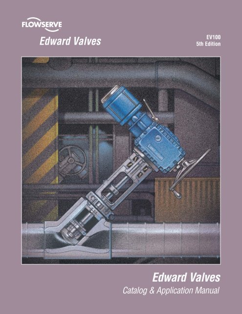
<strong>Edward</strong> <strong>Valves</strong><br />
EV100<br />
5th Edition<br />
<strong>Edward</strong> <strong>Valves</strong><br />
Catalog & Application Manual
<strong>Edward</strong> <strong>Valves</strong><br />
EV100<br />
5th Edition<br />
Introduction<br />
Forged Steel <strong>Valves</strong><br />
Cast Steel <strong>Valves</strong><br />
Special Application <strong>Valves</strong><br />
Nuclear Application <strong>Valves</strong><br />
Accessories/Actuators<br />
Technical<br />
Tables & Charts<br />
Maintenance<br />
A<br />
B<br />
C<br />
D<br />
E<br />
F<br />
G<br />
H<br />
J
Table of Contents<br />
Introduction Page No.<br />
History . . . . . . . . . . . . . . . . . . . . . . . . . . . . . . . A-2<br />
Forged Steel <strong>Valves</strong><br />
Univalve Features . . . . . . . . . . . . . . . . . . . . . . . . B-2<br />
Bolted Bonnet Features . . . . . . . . . . . . . . . . . . . . B-6<br />
Class 600. . . . . . . . . . . . . . . . . . . . . . . . . . . . . . B-8<br />
Class 800. . . . . . . . . . . . . . . . . . . . . . . . . . . . . . B-11<br />
Class 1690 . . . . . . . . . . . . . . . . . . . . . . . . . . . . . B-15<br />
Class 2680 . . . . . . . . . . . . . . . . . . . . . . . . . . . . . B-18<br />
Class 4500 . . . . . . . . . . . . . . . . . . . . . . . . . . . . . B-21<br />
Cast Steel <strong>Valves</strong><br />
Flite-Flow Features . . . . . . . . . . . . . . . . . . . . . . . C-2<br />
Stop-Check Features . . . . . . . . . . . . . . . . . . . . . . C-4<br />
Check Features . . . . . . . . . . . . . . . . . . . . . . . . . . C-5<br />
Tilting Disk Features . . . . . . . . . . . . . . . . . . . . . . C-6<br />
Equiwedge Gate Features . . . . . . . . . . . . . . . . . . . C-8<br />
Class 300. . . . . . . . . . . . . . . . . . . . . . . . . . . . . . C-11<br />
Class 400. . . . . . . . . . . . . . . . . . . . . . . . . . . . . . C-17<br />
Class 600. . . . . . . . . . . . . . . . . . . . . . . . . . . . . . C-20<br />
Class 700. . . . . . . . . . . . . . . . . . . . . . . . . . . . . . C-28<br />
Class 900. . . . . . . . . . . . . . . . . . . . . . . . . . . . . . C-31<br />
Class 1100 . . . . . . . . . . . . . . . . . . . . . . . . . . . . . C-40<br />
Class 1500 . . . . . . . . . . . . . . . . . . . . . . . . . . . . . C-43<br />
Class 1800 . . . . . . . . . . . . . . . . . . . . . . . . . . . . . C-53<br />
Class 2000 . . . . . . . . . . . . . . . . . . . . . . . . . . . . . C-56<br />
Class 2500 . . . . . . . . . . . . . . . . . . . . . . . . . . . . . C-59<br />
Class 2900 . . . . . . . . . . . . . . . . . . . . . . . . . . . . . C-68<br />
Series 4500 . . . . . . . . . . . . . . . . . . . . . . . . . . . . C-71<br />
Special Application <strong>Valves</strong><br />
Features . . . . . . . . . . . . . . . . . . . . . . . . . . . . . . D-2<br />
Blow Off <strong>Valves</strong>. . . . . . . . . . . . . . . . . . . . . . . . . . D-4<br />
Elbow Down <strong>Valves</strong> . . . . . . . . . . . . . . . . . . . . . . . D-9<br />
Hydraulic <strong>Valves</strong> . . . . . . . . . . . . . . . . . . . . . . . . . D-10<br />
Series 1500 . . . . . . . . . . . . . . . . . . . . . . . . . . . . D-12<br />
Strainers . . . . . . . . . . . . . . . . . . . . . . . . . . . . . . D-18<br />
Flanged 1500 Univalves . . . . . . . . . . . . . . . . . . . . D-19<br />
PressurCombo . . . . . . . . . . . . . . . . . . . . . . . . . . D-20<br />
Hermavalve (Commercial) . . . . . . . . . . . . . . . . . . D-24<br />
Nuclear<br />
Features . . . . . . . . . . . . . . . . . . . . . . . . . . . . . . E-2<br />
Hermavalve . . . . . . . . . . . . . . . . . . . . . . . . . . . . E-4<br />
Univalve . . . . . . . . . . . . . . . . . . . . . . . . . . . . . . E-8<br />
Bolted Bonnet . . . . . . . . . . . . . . . . . . . . . . . . . . . E-10<br />
Gas-Hydraulic Actuators . . . . . . . . . . . . . . . . . . . . E-13<br />
Controlled Closure. . . . . . . . . . . . . . . . . . . . . . . . E-14<br />
Page No.<br />
Figure Number Index III<br />
Forged Steel<br />
Availability Chart IV<br />
Cast Steel Availability Chart V<br />
Description of Figure<br />
Number System VI<br />
Flow Control Division<br />
<strong>Edward</strong> <strong>Valves</strong><br />
Accessories/Acutators Page No.<br />
Accessories . . . . . . . . . . . . . . . . . . . . . . . . . . . . F-2<br />
Actuators . . . . . . . . . . . . . . . . . . . . . . . . . . . . . . F-5<br />
Technical Section:<br />
1.0 Stop and Check Valve<br />
Application Guide . . . . . . . . . . . . . . . . . . . . G-4<br />
1.1 Stop Valve Applications . . . . . . . . . . . . . . . . G-4<br />
1.2 Check Valve Appications . . . . . . . . . . . . . . . G-10<br />
1.3 Check & Stop-Check Valve<br />
Installation Guidelines. . . . . . . . . . . . . . . . . G-14<br />
1.4 Check Valve Performance. . . . . . . . . . . . . . . G-19<br />
2.0 Flow Performance. . . . . . . . . . . . . . . . . . . . G-23<br />
2.1 Choose the Best Valve Size for Your<br />
Service Conditions . . . . . . . . . . . . . . . . . . . G-23<br />
2.2 Basic Calculations. . . . . . . . . . . . . . . . . . . . G-23<br />
2.3 Corrections Required with<br />
Large Pressure Drops . . . . . . . . . . . . . . . . . G-26<br />
2.4 Check Valve Sizing . . . . . . . . . . . . . . . . . . . G-28<br />
2.5 Pipe Reducer Coefficients . . . . . . . . . . . . . . G-30<br />
3.0 EDWARD VALVES Design<br />
Standards & Features . . . . . . . . . . . . . . . . . G-59<br />
3.1 Codes and Standards. . . . . . . . . . . . . . . . . . G-59<br />
3.2 Pressure Ratings . . . . . . . . . . . . . . . . . . . . G-59<br />
3.3 Pressure-Seal Construction. . . . . . . . . . . . . . G-60<br />
3.4 Hardfacing. . . . . . . . . . . . . . . . . . . . . . . . . G-61<br />
3.5 Valve-Stem Packing . . . . . . . . . . . . . . . . . . G-61<br />
4.0 Misc. Technical Data . . . . . . . . . . . . . . . . . . G-62<br />
Tables and Charts<br />
Conversion of Measurements. . . . . . . . . . . . . . . . . G-58<br />
Material Specifications. . . . . . . . . . . . . . . . . . . . . H-2<br />
Pressure/Temperature Ratings . . . . . . . . . . . . . . . . H-3<br />
End Preparations. . . . . . . . . . . . . . . . . . . . . . . . . H-29<br />
Maintenance<br />
Maintenance . . . . . . . . . . . . . . . . . . . . . . . . . . . J-2<br />
ii ii <strong>Edward</strong> <strong>Valves</strong> <strong>Valves</strong> • • 1900 1900 South South Saunders Saunders Street, Street, Raleigh, Raleigh, North North Carolina 27603 27603 • 1-800-225-6989 • • 1-919-832-0525 1-919-832-0525 • • Fax 1-919-831-3369<br />
1-919-831-3369
Figure Number Index*<br />
Flow Control Division<br />
<strong>Edward</strong> <strong>Valves</strong><br />
FIGURE NO. PAGE NO. FIGURE NO. PAGE NO. FIGURE NO. PAGE NO. FIGURE NO. PAGE NO. FIGURE NO. PAGE NO.<br />
158 D-10<br />
158Y D-10<br />
160 D-11<br />
160Y D-11<br />
238 D-18<br />
238Y D-18<br />
303 C-13<br />
303Y C-13<br />
304 C-13<br />
304Y C-13<br />
318 C-11<br />
318Y C-11<br />
319 C-11<br />
319Y C-11<br />
329 C-11<br />
329Y C-11<br />
338 D-18<br />
338Y D-18<br />
391 C-15<br />
391Y C-15<br />
394 C-15<br />
394Y C-15<br />
393 C-15<br />
393Y C-15<br />
• 602 C-25<br />
• 602Y C-25, 29<br />
604 C-24<br />
604Y C-24<br />
605 C-24<br />
605Y C-24<br />
606 C-24<br />
606Y C-24<br />
607 C-24<br />
• 607Y C-24<br />
• 614 C-21<br />
• 614Y C-21, 28<br />
616 C-20<br />
616Y C-20<br />
617 C-20<br />
• 617Y C-20<br />
618 C-20<br />
618Y C-20<br />
619 C-20<br />
619Y C-20<br />
• 670Y C-26, 27<br />
690 C-26<br />
690Y C-26<br />
691 C-26<br />
691Y C-26<br />
• 692 C-26, 27<br />
• 692Y C-26, 27, 30<br />
694 C-26<br />
694Y C-26<br />
695 C-26<br />
695Y C-26<br />
• 702Y C-25, 29<br />
706Y C-24<br />
707Y C-24<br />
• 714Y C-21, 28<br />
716Y C-20<br />
717Y C-20<br />
• 770Y C-26, 27<br />
• 792Y C-26, 27, 30<br />
794Y C-26<br />
795Y C-26<br />
• 828 B-8<br />
• 829 B-8<br />
832 B-14<br />
832Y B-14<br />
• These valves can be constructed for nuclear service.<br />
• 838 B-13<br />
• 838Y B-13<br />
• 846 B-9<br />
• 847 B-9<br />
• 848 B-11<br />
• 848Y B-11<br />
• 849 B-11<br />
• 849Y B-11<br />
• 858 B-10<br />
• 868 B-12<br />
• 868Y B-12<br />
• 869 B-12<br />
• 869Y B-12<br />
• 970Y C-37, 38<br />
1028 D-12<br />
1029 D-12<br />
1032 D-17<br />
1032Y D-17<br />
1038 D-16<br />
1038Y D-16<br />
1046 D-14<br />
1047 D-14<br />
1048 D-13<br />
1048Y D-13<br />
1049 D-13<br />
1049Y D-13<br />
1058 D-16<br />
1068 D-15<br />
1068Y D-15<br />
1069 D-15<br />
1069Y D-15<br />
1302 C14<br />
1302Y C14, 18<br />
1314 C-12<br />
1314Y C-12, 17<br />
1324 C-12<br />
1324Y C-12<br />
1390 C-16<br />
1390Y C-16<br />
1392 C-16<br />
1392Y C-16, 19<br />
1441 D-4, 5<br />
1441Y D-4, 5<br />
1443 D-4, 5<br />
1443Y D-4, 5<br />
• 1570Y C-52<br />
• 1611 C-22, 23<br />
• 1611BY C-22, 23<br />
• 1611Y C-22, 23<br />
1641 D-6, 7<br />
1641Y D-6, 7<br />
1643 D-6, 7<br />
1643Y D-6, 7<br />
• 1711BY C-22, 23<br />
• 1711Y C-22, 23<br />
• 1911 C-33<br />
• 1911BY C-33, 34<br />
• 1911Y C-33<br />
• 2002Y C-47, 48, 54<br />
• 2006Y C-47<br />
• 2007Y C-47, 48<br />
• 2014Y C-43, 44, 53<br />
• 2016Y C-43<br />
• 2017Y C-43, 44<br />
• 2070Y C-52<br />
• 2092Y C-49, 51, 55<br />
• 2094Y C-49, 50<br />
• 2095Y C-49, 50<br />
• 2570Y C-62, 64<br />
• 3902Y C-60, 61, 66<br />
• 3906 C-60<br />
• 3906Y C-60<br />
• 3907 C-60, 61<br />
• 3907Y C-60, 61<br />
• 3914Y C-56, 57, 65<br />
• 3916 C-56<br />
• 3916Y C-56<br />
• 3917 C-56, 57<br />
• 3917Y C-56, 57<br />
• 3992Y C-62, 63, 67<br />
• 3994 C-62<br />
• 3994Y C-62<br />
• 3995 C-62, 63<br />
• 3995Y C-62, 63<br />
4002 C-35, 36<br />
4002Y C-35, 36, 41<br />
• 4006 C-35<br />
• 4006Y C-35<br />
• 4007 C-35, 36<br />
• 4007Y C-35, 36<br />
4014 C-31, 32<br />
4014Y C-31, 32, 40<br />
• 4016 C-31<br />
• 4016Y C-31<br />
• 4017 C-31, 32<br />
• 4017Y C-31, 32<br />
4092 C-37, 39<br />
4092Y C-37, 39, 42<br />
• 4094 C-37<br />
• 4094Y C-37<br />
• 4095 C-37, 38<br />
• 4095Y C-37, 38<br />
4302Y C-35, 36, 41<br />
• 4306Y C-35<br />
• 4307Y C-35, 36<br />
4314Y C-31, 32, 40<br />
• 4316Y C-31<br />
• 4317Y C-31, 32<br />
• 4370Y C-37, 38<br />
4392Y C-37, 39, 42<br />
• 4394Y C-37<br />
• 4395Y C-37, 38<br />
• 4402Y C-60, 61, 66<br />
• 4406Y C-60<br />
• 4407Y C-60, 61<br />
• 4414Y C-56, 57, 65<br />
• 4416Y C-56<br />
• 4417Y C-56, 57<br />
4448Y D-9<br />
• 4470Y C-62, 64<br />
• 4492Y C-62, 63, 67<br />
• 4494Y C-62<br />
• 4495Y C-62, 63<br />
4498Y D-9<br />
4502Y C-69<br />
4514Y C-68<br />
4570Y C-71<br />
4592Y C-70<br />
5002Y C-69<br />
5014Y C-68<br />
5070Y C-71<br />
5092Y C-70<br />
5158 D-10<br />
5160 D-11<br />
• 7502Y C-47, 48, 54<br />
• 7506 C-47<br />
• 7506Y C-47<br />
• 7507 C-47, 48<br />
• 7507Y C-47, 48<br />
• 7514Y C-43, 44, 53<br />
• 7516 C-43<br />
• 7516Y C-43<br />
• 7517 C-43, 44<br />
• 7517Y C-43, 44<br />
7548Y D-9<br />
• 7592Y C-49, 51, 55<br />
• 7594 C-49, 50<br />
• 7594Y C-49, 50<br />
• 7595 C-49, 50<br />
• 7595Y C-49, 50<br />
7598Y D-9<br />
9158 D-10<br />
9160 D-11<br />
• 11511 C-45<br />
• 11511Y C-45<br />
• 11511BY C-45, 46<br />
• 12011Y C-45<br />
• 12011BY C-45, 46<br />
• 12511 C-58<br />
• 12511Y C-58<br />
• 12511BY C-58, 59<br />
• 14311Y C-33<br />
• 14311BY C-33, 34<br />
• 14411BY C-58, 59<br />
• 14411Y C-58<br />
• 15004 E-6<br />
• 15008 E-6<br />
• 15014 E-6<br />
• 15018 E-6<br />
• 15104 E-6<br />
• 15108 E-6<br />
• 15114 E-6<br />
• 15118 E-6<br />
16004 D-27<br />
16008 D-27<br />
16014 D-27<br />
16018 D-27<br />
35125 D-28<br />
35129 D-28<br />
35225 D-28<br />
35229 D-28<br />
• 36120 B-15<br />
• 36122 D-19<br />
• 36124 B-15 & D-8<br />
36125 B-24<br />
• 36128 B-15 & D-8<br />
36129 B-24<br />
• 36160 B-16<br />
• 36164 B-16<br />
36165 B-25<br />
• 36168 B-16<br />
36169 B-25<br />
• 36170 B-17<br />
• 36174 B-17<br />
36175 B-26<br />
• 36178 B-17<br />
36179 B-26<br />
• 36220 B-15<br />
• 36222 D-19<br />
• 36224 B-15 & D-8<br />
36225 B-24<br />
• 36228 B-15 & D-8<br />
36229 B-24<br />
• 36260 B-16<br />
• 36264 B-16<br />
36265 B-25<br />
• 36268 B-16<br />
36269 B-25<br />
• 36270 B-17<br />
• 36274 B-17<br />
36275 B-24<br />
• 36278 B-17<br />
36275 B-26<br />
36279 B-26<br />
• 66120 B-18<br />
• 66124 B-18 & D-8<br />
66125 B-27<br />
• 66128 B-18 & D-8<br />
66129 B-27<br />
• 66160 B-19<br />
• 66164 B-19<br />
66165 B-28<br />
• 66168 B-19<br />
66169 B-28<br />
• 66170 B-20<br />
• 66174 B-20<br />
66175 B-29<br />
• 66178 B-20<br />
66179 B-29<br />
• 66220 B-18<br />
• 66224 B-18 & D-8<br />
66225 B-27<br />
• 66228 B-18 & D-8<br />
66229 B-27<br />
• 66260 B-19<br />
• 66264 B-19<br />
66265 B-28<br />
• 66268 B-19<br />
66269 B-28<br />
• 66270 B-20<br />
• 66274 B-20<br />
66275 B-29<br />
• 66278 B-20<br />
66279 B-29<br />
96124 B-21<br />
96128 B-21<br />
96164 B-22<br />
96168 B-22<br />
96174 B-23<br />
96178 B-23<br />
96224 B-21<br />
96228 B-21<br />
96264 B-22<br />
96268 B-22<br />
96274 B-23<br />
96278 B-23<br />
A1611 C-22<br />
A1611Y C-22<br />
A1911 C-33<br />
A1911Y C-33<br />
DSXXXX D-21, 22, 23<br />
DEXXXX D-21, 22, 23<br />
DCXXXX D-21, 22, 23<br />
<strong>Edward</strong> <strong>Valves</strong> • 1900 South Saunders Street, Raleigh, North Carolina 27603 • 1-800-225-6989 • 1-919-832-0525 • Fax 1-919-831-3369 iii
<strong>Edward</strong> Availability Chart<br />
EDWARD FORGED STEEL VALVES<br />
Flow Control Division<br />
<strong>Edward</strong> <strong>Valves</strong><br />
DESCRIPTION PRESSURE RATING*(1) SIZE(1) ENDS PAGE NO.<br />
ANSI 600(110) 1/2(15) thru 2(50) Flanged<br />
B-8<br />
Globe Stop <strong>Valves</strong> ANSI 800(130) 1/4(6) thru 2(50) Threaded, Socket<br />
B-11<br />
Series 1500 1/2(15) thru 2(50) Threaded, Socket, Flanged<br />
D-12 & 13<br />
B-15<br />
Univalve<br />
Globe Stop <strong>Valves</strong><br />
ANSI 1690(290), 2680(460)<br />
& 4500(760)<br />
1/2(15) thru 4(100) Threaded, Socket, Buttwelding B-18<br />
B-21<br />
Hermavalve<br />
Globe Stop <strong>Valves</strong><br />
ANSI to 1690(290)<br />
1/2(15) thru<br />
2-1/2(65)<br />
Socket, Buttwelding<br />
D-27<br />
E-6<br />
ANSI 300(50), 400(68)<br />
Blow Off Stop <strong>Valves</strong> & 600(110)<br />
ANSI 1500(250) & 2500(420)<br />
1-1/2(40) thru<br />
2-1/2(65)<br />
Socket, Flanged, Buttwelding<br />
Socket, Buttwelding<br />
D-4 thru D-7<br />
D-8<br />
Hydraulic Stop <strong>Valves</strong><br />
5,000 PSI CWP<br />
10,000 PSI CWP<br />
1/4(6) thru 2(50) Threaded, Socket, Flanged<br />
D-10<br />
D-11<br />
Globe Stop-Check<br />
<strong>Valves</strong><br />
ANSI 600(110)<br />
ANSI 800(130)<br />
1/2(15) thru 2(50)<br />
1/4(6) thru 2(50)<br />
Flanged<br />
Threaded, Socket<br />
B-9<br />
B-12<br />
Series 1500 1/2(15) thru 2(50) Threaded, Socket, Flanged<br />
D-14 & 15<br />
B-16<br />
Univalve Globe<br />
Stop-Check <strong>Valves</strong><br />
ANSI 1690(290), 2680(460)<br />
&4500(760)<br />
1/2(15) thru 4(100) Threaded, Socket, Buttwelding B-19<br />
B-22<br />
ANSI 600(110) 1/2(15) thru 2(50) Flanged<br />
B-10<br />
Piston Check <strong>Valves</strong> ANSI 800(130) 1/4(6) thru 2(50) Threaded, Socket<br />
B-13<br />
Series 1500 1/4(6) thru 2(50) Threaded, Socket, Flanged<br />
B-22<br />
B-17<br />
Univalve<br />
Piston Check <strong>Valves</strong><br />
ANSI 1690(290), 2680(460)<br />
& 4500(760)<br />
1/2(15) thru 4(100) Threaded, Socket, Buttwelding B-20<br />
B-23<br />
Hydraulic Check<br />
5,000 PSI CWP<br />
<strong>Valves</strong> 10,000 PSI CWP<br />
Ball Check <strong>Valves</strong><br />
Strainers<br />
ANSI 800(130)<br />
Series 1500<br />
ANSI 800(130)<br />
Series 1500<br />
* See paragraph 3.2, page G-59 or definition of various pressure ratings available.<br />
(1) Metric equivalent values for ratings and sizes are in parentheses.<br />
1/4(6) thru 2(50) Threaded, Socket, Flanged<br />
1/4(6) thru 2(50) Threaded, Socket<br />
1/4(6) thru 2(50) Threaded, Socket<br />
Flanged Univalve Class 1500 1/2(15) thru 2(50) Flanged<br />
Univalve Angle ANSI 1690 1/2(15) thru 4(50) Socket, Buttwelding<br />
Stop, Stop-Check<br />
& Check <strong>Valves</strong><br />
ANSI 2680<br />
iv <strong>Edward</strong> <strong>Valves</strong> • 1900 South Saunders Street, Raleigh, North Carolina 27603 • 1-800-225-6989 • 1-919-832-0525 • Fax 1-919-831-3369<br />
D-11<br />
B-14<br />
D-17<br />
D-18<br />
D-19<br />
B-24 thru<br />
B29
<strong>Edward</strong> Availability Chart<br />
EDWARD CAST STEEL GATE, GLOBE, ANGLE AND CHECK VALVES<br />
DESCRIPTION PRESSURE RATING*(1) SIZE(1) ENDS PAGE NO.<br />
Bolted Bonnet Globe and<br />
ANSI 300(50) 2-1/2(65) thru 12(300)<br />
C-11, 13 & 15<br />
Angle <strong>Valves</strong>, Stop and<br />
Stop-Check (Non-Return) and<br />
Bolted Cover Piston Check<br />
ANSI 600(110) 2-1/2(65) thru 69150)<br />
Buttwelding<br />
or Flanged<br />
C-20, 24, 26<br />
Pressure Seal Bonnet<br />
ANSI 600(110) 8(200) thru 14(350)<br />
Globe and Angle <strong>Valves</strong><br />
Stop and Stop-Check<br />
(Non-Return)<br />
ANSI 900(150)<br />
ANSI 1500(250) & 2500(420)<br />
3(80) thru 24(600)<br />
2-1/2(65) thru 24(600)<br />
Buttwelding<br />
or Flanged<br />
Pressure Seal Cover,<br />
Piston Check <strong>Valves</strong><br />
ANSI 600(110)<br />
ANSI 900(150)<br />
ANSI 1500(250) & 2500(420)<br />
8(200) thru 14(350)<br />
8(200) thru 24(600)<br />
2-1/2(65) thru 24(600)<br />
Buttwelding<br />
or Flanged<br />
Equiwedge ® Gate <strong>Valves</strong><br />
ANSI 600(110) & 900(150)<br />
ANSI 1500(260) & 2500(420)<br />
2-1/2(65) thru 32(800)<br />
2-1/2(65) thru 24(600)<br />
Buttwelding<br />
or Flanged<br />
ANSI 300(50) 3(80) thru 16(400)<br />
Flite-Flow® Globe <strong>Valves</strong>,<br />
Stop and Stop-Check<br />
(Non-Return)<br />
ANSI 400(68)<br />
ANSI 600(110)<br />
ANSI 700(120)<br />
3(80) thru 4(100)<br />
3(80) thru 32(800)<br />
6(150) thru 32(800)<br />
Buttwelding<br />
or Flanged<br />
ANSI 900(150) 6(150) thru 16(400)<br />
ANSI 1100(190) 3(80) thru 4(100)<br />
ANSI 1500(260) & 2500(420) 3(80) thru 24(600)<br />
ANSI 1800(310) & 2900 (490) 3(80) thru 4(100)<br />
Series 4500 4(100) thru 10(250)<br />
ANSI 300(50) 3(80) thru 16(400)<br />
Flite-Flow®<br />
Piston Check <strong>Valves</strong><br />
ANSI 400(68)<br />
ANSI 600(110)<br />
3(80) thru 4(100)<br />
3(80) thru 32(800)<br />
Buttwelding<br />
or Flanged<br />
ANSI 700(120) 6(150) thru 32(800)<br />
ANSI 900(150) 6(150) thru 16(400)<br />
ANSI 1100(190) 3(80) thru 4(100)<br />
ANSI 1500(260) & 2500(420) 3(80) thru 24(600)<br />
ANSI 1800(310) & 2900 (490) 3(80) thru 4(100)<br />
Series 4500 4(100) thru 10(250)<br />
ANSI 600(110) 6(150) thru 20(500)<br />
Tilting Disk<br />
Check <strong>Valves</strong><br />
900(150), 1500(260) &<br />
2500(420)<br />
2-1/2(65) thru 24(600) Buttwelding<br />
Class 4500(760) 6(150) & 8(200)<br />
Nuclear <strong>Valves</strong> Thru ANSI 2500(420) to Size 32(800) Buttwelding<br />
Special Application <strong>Valves</strong> Thru ANSI 2500(420) to Size 18(450) As Required<br />
* See paragraph 3.2, page G-59 for definition of various pressure ratings available.<br />
(1) Metric equivalent values for ratings and sizes are in parentheses.<br />
C-20, 24<br />
C-31, 32, 35, 36<br />
C-43, 44, 47, 48, 56,<br />
57, 60, 61<br />
C-26<br />
C-37<br />
C-49, 50, 62, 63<br />
C-22, 23, 33, 34<br />
C-45, 46, 58, 59<br />
C-12 & 14<br />
C-17 & 18<br />
C-21, 25<br />
C-28, 29<br />
C-32, 35, 36<br />
C-40, 41<br />
C-43, 44, 47, 48,<br />
56, 57, 60, 61<br />
C-53, 54, 65, 66<br />
C-68, 69<br />
C-16<br />
C-19<br />
C-27<br />
C-30<br />
C-37, 39<br />
C-42<br />
C-49, 51, 62, 63<br />
C-55, 67<br />
C-70<br />
C-27<br />
C-38, 52, 64<br />
C-71<br />
E-2 thru 14<br />
D-3 & 9<br />
Flow Control Division<br />
<strong>Edward</strong> <strong>Valves</strong><br />
<strong>Edward</strong> <strong>Valves</strong> • 1900 South Saunders Street, Raleigh, North Carolina 27603 • 1-800-225-6989 • 1-919-832-0525 • Fax 1-919-831-3369 v
<strong>Edward</strong> Description of Figure Number System<br />
Special Material Suffixes Special Feature Suffixes<br />
CF8C - Cast 18-8 stainless steel (type 347) body<br />
and bonnet. Parts in contact with line fluid<br />
either cast or forged 18-8 stainless steel<br />
or equivalent.<br />
CF3M - Cast 18-8 stainless steel (type 316L) body<br />
and bonnet. Parts in contact with line fluid<br />
either cast or forged 18-8 stainless steel<br />
or equivalent.<br />
CF8M - Cast 18-8 stainless steel (type 316) body<br />
and bonnet. Parts in contact with line fluid<br />
either cast or forged 18-8 stainless steel<br />
or equivalent.<br />
C5 - Cast chromium molybdenum (5 chromium<br />
1/2 molybdenum) Grade C5 alloy steel<br />
body and bonnet. Trim of equal or higher<br />
grad alloy steel.<br />
F11 - Body and bonnet of forged chromium<br />
molybdenum (1-1/4 chromium, 1/2<br />
molybdenum) Grade F11 alloy steel.<br />
F22 - Body and bonnet of forged chromium<br />
molybdenum (2-1/4 chromium, 1<br />
molybdenum) Grade F22 alloy steel.<br />
F91 - Body and bonnet of forged chromium<br />
molybdenum (9 chromium, 1<br />
molybdenum) Grade F91 alloy steel.<br />
F316 - Body and bonnet of forged Type 316<br />
stainless steel.<br />
F316L - Body and bonnet of forged Type 316L<br />
stainless steel.<br />
F347 - Body and bonnet of forged Type 347<br />
stainless steel.<br />
F347H - Body and bonnet of forged Type 347H<br />
stainless steel.<br />
LF2 - Forged carbon steel material on which<br />
Charpy impact tests have been performed<br />
on forging heat to determine low<br />
temperature<br />
properties.<br />
WC1 - Cast carbon molybdenum Grade WC1<br />
body and bonnet.<br />
WC6 - Cast chromium molybdenum (1-1/4<br />
chromium, 1/2 molybdenum) Grade WC6<br />
alloy steel body and bonnet.<br />
WC9 - Cast chromium molybdenum (2-1/4<br />
chromium, 1 molybdenum) Grade WC9<br />
alloy steel body and bonnet.<br />
WCC - Cast carbon steel Grade WCC body and<br />
bonnet.<br />
C12A - Cast chromium molybdenum<br />
(9 chromium, 1 molybdenum)<br />
alloy steel body and bonnet.<br />
XX<br />
1 Alpha Digit Indicates Design Revision if Applicable.<br />
2 Alpha Digits Indicates Style of Pressure Combo Valve<br />
(See Page D20).<br />
XXXXX<br />
3-5 Digits Figure Number<br />
(XXX)<br />
3-4 Digits Body Material Designation<br />
XXXXXXX<br />
1 or more Digits As Required Suffixes (See List)<br />
A - Special body only - body pattern<br />
alterations not required. Flanges on forged<br />
valves not normally supplied with flanges.<br />
On socket end forged steel valves the inlet<br />
and outlet ends are different.<br />
B - Venturi pattern body.<br />
C - Locking devices consisting of padlock and<br />
chain.<br />
CD - Locking devices, indicator type.<br />
DD - Equalizer external.<br />
DDI - Equalizer internal.<br />
E - Permanent drain, hole in disk or groove in<br />
disk face.<br />
F - Special trim material: used to designate<br />
special disk material, special stem<br />
material, or inconel spring in check valves.<br />
FF - Special yoke bushing material, such as<br />
Austenitic Nodular Iron.<br />
G - By passes on all types of cast steel valves<br />
H - Spur gear operation.<br />
HH - Bevel gear operation.<br />
HHL - Valve less bevel gear actuator but with<br />
actuator mounting equipment.<br />
J - Any unclassified special.<br />
K - Throttle disk or skirted disk.<br />
L - Impactor operated. Used now only to<br />
indicate impactor handwheel or handle on<br />
valves not regularly furnished with<br />
impactor.<br />
LD - Impactorgear or Impactodrive.<br />
Flow Control Division<br />
<strong>Edward</strong> <strong>Valves</strong><br />
M - Motor actuated.<br />
ML - Valve less actuator but with motor<br />
actuator mounting equipment.<br />
MM - Cylinder/diaphragm actuated. Either<br />
hydraulic or pneumatic.<br />
MML - Valve less cylinder/diaphragm actuator but<br />
with actuator mounting equipment.<br />
N - Body drilled and tapped or socketed for<br />
drains, with or without nipple, with or<br />
without drain valves.<br />
P - Non-standard packing of all types.<br />
PL - Plastic lined.<br />
Q - Non-standard bonnet gaskets or gasket<br />
plating.<br />
R - Special lapping and honing and gas<br />
testing (recommended for valves on high<br />
pressure gas service).<br />
S - Smooth finish on contact faces of end<br />
flanges<br />
T - Critical service requiring special testing<br />
and/or NDE.<br />
W - Stellited seat and disk. Suffix not used for<br />
valves that are cataloged as having<br />
stellited seat and disk as standard.<br />
X - Ring joint facing on body end flanges.<br />
Y - All welding ends either socket or butt.<br />
Suffix not used for valves where figure<br />
number designates welding ends as<br />
standard, such as Fig. 36224 and 66228<br />
for example.<br />
T1 - ASME Section III Class 1 compliance.<br />
T2 - ASME Section III Class 2 compliance.<br />
T3 - ASME Section III Class 3 compliance.<br />
T4 - ASME Section III compliance without “N”<br />
stamp.<br />
T5 - Nuclear safety related-10CFR21 invoked.<br />
Unless otherwise specified when ordering <strong>Edward</strong> valves, the standard material of construction for<br />
Forged products is A105 Carbon Steel, and for Cast products is A216 Grade WCB Carbon Steel.<br />
Listed below are the letter suffixes used to indicate variations from standard construction, or special<br />
features (Ex. 618K, 7506 [WC6]Y, and 847 AH.)<br />
When two or more suffixes follow a figure number a definite suffix sequence is to be used.<br />
The sequence is:<br />
1) Special material (if applicable)<br />
2) All other applicable feature suffixes in alphabetical order.<br />
Except T1-T5 which are listed last.<br />
vi <strong>Edward</strong> <strong>Valves</strong> • 1900 South Saunders Street, Raleigh, North Carolina 27603 • 1-800-225-6989 • 1-919-832-0525 • Fax 1-919-831-3369
<strong>Edward</strong> <strong>Valves</strong><br />
EV100<br />
5th Edition<br />
Introduction A
High Performance<br />
For Critical Service<br />
Temperatures that can exceed 1000° F. Pressures<br />
surpassing 10,000 psi. In critical service conditions, you<br />
can’t take chances. You don’t just meet standards, you<br />
exceed them. That’s how <strong>Edward</strong> forged and cast steel<br />
valves have become the specified choice for power plants,<br />
process facilities, and other high-temperature, highpressure<br />
services.<br />
Conservative Design<br />
<strong>Edward</strong> <strong>Valves</strong> takes a conservative approach<br />
to valve design. We meet all applicable codes<br />
and standards, but we go beyond that...with<br />
finite element stress analysis of critical areas<br />
and rigorous proof testing. <strong>Edward</strong> valves are<br />
built to take punishment!<br />
And our extensive testing has also allowed us<br />
to develop extremely high flow efficiencies in<br />
all our valves.<br />
You’ll find other unique design advantages on<br />
our various product lines, such as our<br />
Equiwedge gate valves, with a two-piece<br />
wedge gate assembly which adjusts<br />
automatically to any angular distortion of the<br />
body seats. And many other design features,<br />
now considered industry “standards,” started<br />
on the drawing boards at <strong>Edward</strong> <strong>Valves</strong>.<br />
Precision Manufacturing<br />
<strong>Edward</strong> <strong>Valves</strong> also exceeds industry<br />
standards on the factory floor. Our forged<br />
valves are produced on a fully automated line,<br />
with CNC machining centers providing precise<br />
process control. And we maximize cast steel<br />
quality by producing our valve body castings<br />
using a directional solidification process from<br />
patterns designed by our own technicians.<br />
This process assures high strength void free<br />
castings for uncompromised quality.<br />
Even with the most advanced equipment, we<br />
feel our people make the real difference at<br />
<strong>Edward</strong> <strong>Valves</strong>. Our production personnel have<br />
an average 20 years in the industry, and 15<br />
years with <strong>Edward</strong> <strong>Valves</strong>! This exceptional<br />
experience level allows us to achieve an extra<br />
degree of precision that can make a very real<br />
difference in the field.<br />
Finally, it’s our people, along with our<br />
procedures for quality assurance and lottraceability,<br />
that have earned <strong>Edward</strong> <strong>Valves</strong><br />
the ASME N stamp, certifying our Raleigh, North<br />
Carolina, manufacturing facility for nuclearservice<br />
valve production.<br />
Flow Control Division<br />
<strong>Edward</strong> <strong>Valves</strong><br />
Lower Total Costs<br />
Those tough standards have carried over into<br />
every valve we manufacture. Whether it is for<br />
nuclear service or not, we design and build<br />
our valves to last at least 40 years. That<br />
means not only are they tough, but they are<br />
designed with easy maintenance in mind.<br />
Considering the cost of valve failure, <strong>Edward</strong><br />
<strong>Valves</strong> quality is clearly worth specifying.<br />
That’s been true since 1904, when the first<br />
<strong>Edward</strong> valve was made.<br />
Today, as industrial companies become<br />
increasingly aware that operating expenses are<br />
part of total cost, the choice becomes both<br />
more clear and more critical than ever.<br />
A2 <strong>Edward</strong> <strong>Valves</strong> • 1900 South Saunders Street, Raleigh, North Carolina 27603 • 1-800-225-6989 • 1-919-832-0525 • Fax 1-919-831-3369
Designed With An Eye On<br />
Your Bottom Line<br />
In-house computer-aided design and finiteelement<br />
method capabilities give our<br />
engineering staff powerful tools to develop<br />
reliable valves for critical service applications.<br />
CAD generated graphic models undergo FEM<br />
analysis to determine that stresses are within<br />
acceptable limits. Dynamic simulation of valve<br />
operation also helps assure reliability of<br />
<strong>Edward</strong> valve performance.<br />
Prototyping is just as important, and rigorous<br />
proof testing is a mainstay of <strong>Edward</strong> valve<br />
design. Before we approve a valve for<br />
production, we put it through hundreds, even<br />
thousands, of cycles to demonstrate that<br />
performance and sealing integrity will be<br />
maintained in service. Transducers relay data<br />
from test assemblies to computers for further<br />
analysis.<br />
Laboratory simulation of critical services<br />
includes a steam generator and superheater,<br />
designed for 2700 psi and 1050° F. This<br />
flexible system allows testing of prototype<br />
valves under both low pressure and high<br />
pressure conditions. In addition to prototype<br />
testing, this system has been used for<br />
applications such as: friction and wear tests<br />
of valve trim materials in hot water and steam<br />
environments; qualification tests of<br />
new or redesigned valves; and proof testing<br />
of new valve gaskets and valve stem<br />
packings.<br />
Before we make the first production unit, that<br />
valve has already been through a rigorous<br />
program to assure long life, simple<br />
maintenance, and dependable performance,<br />
for the lowest cost over the life of the valve.<br />
Again, people play important roles in design.<br />
The <strong>Edward</strong> product engineering department<br />
pools well over 200 years of valve experience.<br />
Testing Beyond Code<br />
Requirements<br />
At <strong>Edward</strong> <strong>Valves</strong>, quality assurance starts<br />
with meeting code requirements. <strong>Valves</strong> are<br />
manufactured to ANSI B16.34 (Standard,<br />
Limited and Special Classes), including<br />
standards for:<br />
• Minimum wall thickness of valve body.<br />
• Body, bonnet and body-bonnet bolting to<br />
specified ASTM material standards.<br />
• Hydrostatic shell testing at 1.5 times the<br />
100° F rating of the valve.<br />
From there, <strong>Edward</strong> <strong>Valves</strong> goes on to exceed<br />
the code, with higher test standards and an<br />
additional battery of tests performed on every<br />
type of valve we make, using in-house test<br />
facilities and personnel to assure expert<br />
quality control. <strong>Edward</strong> <strong>Valves</strong>’ quality<br />
assurance program includes:<br />
Non-Destructive Examination<br />
• All NDE personnel are qualified in<br />
accordance with ASNT-TC-1A guide lines.<br />
• All castings are visually examined per MSS<br />
SP-55.<br />
• The first five body castings from every<br />
pattern are 100% radiographed to verify<br />
casting quality.<br />
Hydrostatic Testing<br />
•The seat-leakage criteria⎯no visible leakage<br />
for forged steel and 2ml/hour/ inch of<br />
nominal valve size for cast steel⎯are<br />
stricter than the allowed leakage rate of<br />
MSS SP-61, which is 10ml/hour/inch of<br />
nominal valve size.<br />
•Seat-leakage test is performed at 110% of<br />
100° F rating.<br />
Statistical Process Control<br />
Requirements are clearly stated and<br />
measurements are taken to determine<br />
conformance to those requirements. “Quality”<br />
equals conformance to requirements.<br />
Welding<br />
All personnel and procedures are qualified in<br />
accordance with ASME Boiler and Pressure<br />
Vessel Code, Section IX.<br />
Additional Standard Tests for<br />
Specific <strong>Valves</strong><br />
Includes heavy-wall examination on large<br />
body castings.<br />
Flow Control Division<br />
<strong>Edward</strong> <strong>Valves</strong><br />
We have only listed a few of <strong>Edward</strong> <strong>Valves</strong>’<br />
standard tests that exceed industry<br />
requirements. Also, <strong>Edward</strong> <strong>Valves</strong> has the<br />
facilities and the expertise to meet additional<br />
quality-assurance standards, as required for<br />
the application.<br />
<strong>Edward</strong> <strong>Valves</strong> • 1900 South Saunders Street, Raleigh, North Carolina 27603 • 1-800-225-6989 • 1-919-832-0525 • Fax 1-919-831-3369 A3<br />
A
A History of Firsts<br />
Feature<br />
Body-guided disks on globe and angle<br />
valves<br />
Integral Stellite hardfaced seats in globe and<br />
angle valves<br />
Hermetically sealed globe valves with sealwelded<br />
diaphragms<br />
Equalizers for large check and stop-check<br />
valves<br />
Compact pressure-seal bonnet<br />
joints<br />
Qualified stored-energy actuators<br />
Qualified valve-actuator combinations<br />
Stainless steel spacer rings on gate valves,<br />
fitted between wedge halves<br />
Unique two-piece, flexible wedges on gate<br />
valves<br />
Impactor handwheels and handles<br />
Inclined-bonnet globe valves with<br />
streamlined flow passages<br />
Globe valves available with both vertical and<br />
inclined stems<br />
Live-loaded pressure energized<br />
PressurSeat for globe valves<br />
Flow Control Division<br />
<strong>Edward</strong> <strong>Valves</strong><br />
A4 <strong>Edward</strong> <strong>Valves</strong> • 1900 South Saunders Street, Raleigh, North Carolina 27603 • 1-800-225-6989 • 1-919-832-0525 • Fax 1-919-831-3369<br />
Benefit<br />
Minimize wear and ensure alignment for<br />
tight sealing.<br />
Permit compact design and resist<br />
erosion.<br />
Prevent stem leakage in critical nuclear plant<br />
applications.<br />
Ensure full lift at moderate flow rates, and<br />
prevent damage due to instability.<br />
Eliminate massive bolted flanges on large,<br />
high-pressure valves.<br />
Allow quick-closing valves in safety-related<br />
nuclear plant applications.<br />
Used in main steam and feed-water<br />
service throughout the world.<br />
Simplify service. Damaged valve seats can<br />
be restored to factory fit by in-line<br />
replacement with slightly thicker ring.<br />
Automatically adjust to any angular<br />
distortion of body seats. Shape provides<br />
greater flexibility. Assure dependable sealing<br />
and prevent sticking.<br />
Allow workers to generate several<br />
thousand foot-pounds of torque, thus<br />
ensuring tight shutoff of manually<br />
operated globe and angle valves.<br />
Minimize pressure drop due to flow.<br />
Provide stem designs suited to any<br />
installation.<br />
Globe valve design for high pressure drain<br />
and vent service.
<strong>Edward</strong> <strong>Valves</strong><br />
EV100<br />
5th Edition<br />
A<br />
Forged Steel <strong>Valves</strong> B
Features and Description of <strong>Edward</strong> Univalve ® Globe <strong>Valves</strong><br />
8.<br />
7.<br />
9.<br />
10.<br />
11.<br />
12.<br />
1. Stem has ACME threads, is ground to a fine finish<br />
and is hardened to resist wear.<br />
2. Yoke bushing material has low coefficient of friction<br />
which substantially reduces torque and stem<br />
wear and eliminates galling. Mechanical upset locks<br />
yoke bushing to yoke.<br />
3. Yoke-bonnet assembly is two piece to facilitate<br />
disassembly for faster in-line internal repairs.<br />
4. Inclined stem construction and optimum flow<br />
shape minimizes flow direction changes and reduces<br />
pressure drop.<br />
5. Body-guided disk utilizes anti-thrust rings to<br />
eliminate misalignment, galling and stem bending.<br />
6. Integral hardsurfaced seat provides positive<br />
shutoff and long seat life.<br />
7. Handwheel on smaller size valves is rugged and<br />
knobbed to provide sure grip even when wearing<br />
gloves. Impactor handle or handwheel on larger,<br />
higher pressure valves provides many times the<br />
closing force of an ordinary handwheel for positive<br />
seating.<br />
8. Threaded bonnet has ACME threads for resistance<br />
to galling and ease of disassembly. Unwelded<br />
models utilize a graphitic gasket for dependable<br />
sealing. Welded models employ a fillet weld (canopy<br />
weld on stainless steel valves) for absolute protection<br />
from body-bonnet leakage.<br />
Flow Control Division<br />
<strong>Edward</strong> <strong>Valves</strong><br />
9. Stem packing system utilizes flexible graphite<br />
packing material with carbon fiber anti-extrusion<br />
rings for optimum sealability and life.<br />
10. Bonnet locking collar. (unwelded valves only)<br />
11. Bonnet seal ring is die formed flexible graphite<br />
gasket seated to a prescribed bonnet torque to provide<br />
reliable bonnet seal.<br />
12. Integral backseat provides a secondary stem<br />
seal back up for positive shutoff and leak protection.<br />
B2 <strong>Edward</strong> <strong>Valves</strong> • 1900 South Saunders Street, Raleigh, North Carolina 27603 • 1-800-225-6989 • 1-919-832-0525 • Fax 1-919-831-3369<br />
1<br />
2.<br />
3.<br />
4.<br />
5.<br />
6.
Part Specification List for <strong>Edward</strong> Univalve ®<br />
Flow Control Division<br />
This is not a complete list. Construction and materials will vary between sizes and pressure classes and may be changed without notice.<br />
For a complete, accurate, and itemized description of a particular valve, contact your <strong>Edward</strong> <strong>Valves</strong> sales representative.<br />
Body A-105 A-182 A-182 A-182<br />
<strong>Edward</strong> <strong>Valves</strong><br />
DESCRIPTION ASTM NO. ASTM NO. ASTM NO. ASTM NO.<br />
⎯ Grade F-22 Grade F-316/F-347* Grade F91<br />
Bonnet A-696 A-739 A-479 A-182<br />
Grade C Grade B-22 T-316/347 Grade F91<br />
Stem A-479 A-479 A-638 A-638<br />
T-410CL3 T-410CL3 Grade 660 Grade 660<br />
Disk A-732 A-732 A-732 A-732<br />
Grade 21 Grade 21 Grade 21 Grade 21<br />
Body Seat Stellite 21 Stellite 21 Stellite 21 Stellite 21<br />
Junk Ring ⎯ ⎯ A-732 —<br />
⎯ ⎯ Grade 21 —<br />
Packing Rings Flexible Graphite System Flexible Graphite System Flexible Graphite System Flexible Graphite System<br />
Gland A-668 A-668 A-182 A-668<br />
Grade 4140 Grade 4140 Grade F6a Grade 4140<br />
Gland Adjusting Screw A-582 A-582 A-582 A-582<br />
T-416 T-416 T-416 T-416<br />
Yoke A-181 A-181 A-181 A-181<br />
Class 70 Class 70 Class 70 Class 70<br />
Yoke Bushing B150 Alloy C61900 or C62300 B150 Alloy C61900 or C62300 B150 Alloy C61900 or C62300 B150 Alloy C61900 or C62300<br />
Yoke Bolt A-307 A-307 A-307 A-307<br />
Grade A Grade A Grade A Grade A<br />
Yoke Nut A-563 Grade A A-563 Grade A A-563 Grade A A-563 Grade A<br />
Handwheel/Impactor Handle Malleable or Malleable or Malleable or Malleable or<br />
Adapter Ductile Iron Ductile Iron Ductile Iron Ductile Iron<br />
Stem Nut/Washer Mild Steel Mild Steel Mild Steel Mild Steel<br />
Plated Plated Plated Plated<br />
Bonnet Seal Ring** Flexible Flexible Flexible Flexible<br />
Graphite Graphite Graphite Graphite<br />
Bonnet Insert† A-582 A-582 A-479 A-582<br />
T-416 T-416 T-316 T-416<br />
Locking Collar††† Carbon Carbon Carbon Carbon<br />
Steel Steel Steel Steel<br />
Spring†† A-313 A-313 A-313 INCONEL<br />
T-302 T-302 T-302 X-750<br />
Parts shown above are not applicable to all Univalve® valves.<br />
* Other Stainless grades available on application.<br />
** Used in unwelded and Class 4500 welded design only.<br />
† Class 4500 welded design only.<br />
†† Check valves only.<br />
††† Unwelded valves only.<br />
<strong>Edward</strong> <strong>Valves</strong> • 1900 South Saunders Street, Raleigh, North Carolina 27603 • 1-800-225-6989 • 1-919-832-0525 • Fax 1-919-831-3369 B3<br />
A<br />
B
<strong>Edward</strong> Forged Steel <strong>Valves</strong> Feature Body-Guided Disks<br />
To Prevent Side-Thrust and Eliminate –<br />
1. Stem galling & binding 2. Disk-seat misalignment and damage 3. High operating torque<br />
Valve disks are guided by rings that fit snugly within the body bore and assure perfect<br />
disk-and-seat alignment despite the side thrust of modern high velocities and<br />
high pressure-differentials. This protects the stem and its contact points; eliminates<br />
galling, scoring, bending and the high operating torque resulting from these abuses.<br />
Because they eliminate disk wobble and assure alignment of disk with seat, they also<br />
assure more dependable closing and longer disk, seat and body life.<br />
Double Duty for Lower Bearing - The lower ring not only serves as a highly efficient<br />
anti-side thrust bearing but serves too, as a “flow director.” Its snug fit within the<br />
bonnet bore reduces by 90% the amount of flow that can get into the bonnet cavity<br />
and exert thrust forces against the side of the disk. In short, the anti-thrust ring<br />
design diverts 90% of the line forces into controllable channels.<br />
Machining Important, Too - To assure concentric alignment essential to tight seating,<br />
the body bore and the stellite seat are both machined in a single operation. The disk’s<br />
anti-thrust rings and conical stellite seat face are also faced in a single operation.<br />
Streamlined Flow Passages for Highest CV Values - The inclined bonnet globe<br />
stopvalves (and check and stop-check valves) continue the <strong>Edward</strong> reputation for the<br />
ultimate in flow passage streamlining. Inclined bonnet construction minimizes flow<br />
directional changes and minimizes wear caused by excessive turbulence.<br />
Whether it’s pounds per hour of steam or gallons per minute of liquid, the inclined<br />
bonnet valves give you better flow capacity.<br />
Flow Under or Over Disk - Normal practice is to install globe valves with flow entering<br />
from below the disk. However, piping designers may confidently install <strong>Edward</strong><br />
globe stop valves with flow entering over the disk when space problems or other<br />
considerations suggest this procedure. Our valves operate equally well with flow in<br />
either direction; however, with flow over the disk, packing is under pressure when the<br />
valve is closed and there is a slight penality in CV value.<br />
Figure 4 - Graph illustrates relationship of side-thrust in conventional<br />
stem-guided Globe Valve and in <strong>Edward</strong> Univalve with body-guided disk.<br />
Figure 1 - Ordinary Vertical Stem<br />
Globe <strong>Valves</strong> are subject to sidethrust<br />
under high pressure drop<br />
conditions. Illustration shows how<br />
upstream pressure can slip past<br />
stem-guided disk and impart a<br />
thrust toward the downstream side<br />
of the valve. Tests have proven that<br />
this thrust causes disk-seat misalignment<br />
plus galling and scoring.<br />
Figure 2 - Inclined Stem Globe<br />
<strong>Valves</strong> of the stem-guided type are<br />
also subject to side-thrust under<br />
the same conditions. Illustration<br />
above shows path pressure through<br />
the valve.<br />
Figure 3 - This illustration shows the<br />
<strong>Edward</strong> body-guided disk with antithrust<br />
rings. Lower guide eliminates<br />
90% of the flow upward and behind<br />
the disk. Both guide rings maintain<br />
perfect alignment. This effectively<br />
eliminates all side-thrust problems.<br />
Figure 5 - Graph illustrates typical throttling curves for conventional<br />
stem-guided Globe Valve and Univalve. Note, the Univalve Curve illustrates<br />
that finest control is obtained at low lifts, when it is needed.<br />
Contrast this with conventional valve curve which shows rapid flow<br />
increase as disk lifts off seat.<br />
Flow Control Division<br />
<strong>Edward</strong> <strong>Valves</strong><br />
B4 <strong>Edward</strong> <strong>Valves</strong> • 1900 South Saunders Street, Raleigh, North Carolina 27603 • 1-800-225-6989 • 1-919-832-0525 • Fax 1-919-831-3369
Here’s How The Unique Stem-Disk Assembly is Made...<br />
Figure 1<br />
First, a Stellite wire is inserted into a hole in a<br />
Univalve body guided disk.<br />
Figure 2<br />
Next, the Stellite wire is fed around circular<br />
grooves, adjacent to one another, on the inside<br />
bore of the disk and outside diameter of the stem.<br />
Flow Control Division<br />
<strong>Edward</strong> <strong>Valves</strong><br />
Figure 3<br />
Finally the hole through which the wire was fed is<br />
welded closed.<br />
<strong>Edward</strong> <strong>Valves</strong> • 1900 South Saunders Street, Raleigh, North Carolina 27603 • 1-800-225-6989 • 1-919-832-0525 • Fax 1-919-831-3369 B5<br />
A<br />
B
Features and Description of <strong>Edward</strong> Bolted Bonnet Globe <strong>Valves</strong><br />
1. Handwheel is rugged and knobbed to provide<br />
sure grip even when wearing gloves.<br />
2. Stem has ACME threads, is ground to a fine finish<br />
and is hardened to resist wear.<br />
3. Yoke bushing material has low coefficient of friction<br />
which substantially reduces torque and stem<br />
wear and eliminates galling. Mechanical upset locks<br />
yoke bushing to yoke.<br />
4. Bolted Bonnet joint utilizes a spiral wound gasket<br />
for positive sealing and four-bolt design for ease of<br />
assembly. Bonnet has pilot extension to insure proper<br />
alignment and positive metal to metal stop to prevent<br />
over-compression of gasket.<br />
5. Integral hardsurfaced seat provides positive<br />
shutoff and long seat life.<br />
6. Stem packing system utilizes flexible graphite<br />
packing material with anti-extrusion rings for optimum<br />
sealability and life.<br />
Flow Control Division<br />
<strong>Edward</strong> <strong>Valves</strong><br />
7. Integral backseat provides a secondary stem seal<br />
backup for positive shutoff and leak protection.<br />
8. Body utilizes optimized flow passages to minimize<br />
flow direction changes and reduce pressure drop.<br />
9. Body-guided disk utilizes anti-thrust rings to<br />
eliminate misalignment, galling and stem bending.<br />
B6 <strong>Edward</strong> <strong>Valves</strong> • 1900 South Saunders Street, Raleigh, North Carolina 27603 • 1-800-225-6989 • 1-919-832-0525 • Fax 1-919-831-3369
Part Specification List for <strong>Edward</strong> Bolted Bonnet Globe <strong>Valves</strong><br />
Flow Control Division<br />
<strong>Edward</strong> <strong>Valves</strong><br />
This is not a complete list. Construction and materials will vary between sizes and pressure classes and may be changed without notice. For a<br />
complete, accurate, and itemized description of a particular valve, contact your <strong>Edward</strong> <strong>Valves</strong> sales representative.<br />
DESCRIPTION<br />
Body/Bonnet<br />
Disk<br />
BOLTED BONNET<br />
ASTM NO. ASTM NO.<br />
A-105 A-182<br />
— Grade F11<br />
AISI 615 AISI 615<br />
Stainless Steel Stainless Steel<br />
Body Seat Stellite 21 Stellite 21<br />
Stem<br />
Cap Screws<br />
Gasket<br />
A-582 A-582<br />
T-416 T-416<br />
A-193 A-193<br />
Grade B-7 Grade B-7<br />
Spiral Wound Spiral Wound<br />
Non Asbestos Non-Asbestos<br />
Packing Flexible Graphite System Flexible Graphite System<br />
Gland<br />
A-536 A-536<br />
GR. 80-55-06 GR. 80-55-06<br />
Yoke Bushing B-150 C61900 or C62300 B-150 C61900 or C62300<br />
Handwheel/Handle<br />
Malleable or Malleable or<br />
Ductile Iron Ductile Iron<br />
Stem Nut Mild Steel-Plated Mild Steel-Plated<br />
Eye Bolt<br />
Eye Bolt Nut<br />
Eye Bolt Pin<br />
Spring**<br />
Ball**<br />
**Check valves only<br />
NOTES: Parts shown above are not applicable to all Bolted Bonnet valves.<br />
Consult your <strong>Edward</strong> <strong>Valves</strong> sales representative for special applications.<br />
A-582 A-582<br />
T-416 T-416<br />
A-563 A-563<br />
Grade A Grade A<br />
AISI AISI<br />
Grade 4140 Grade 4140<br />
A-313 A-313<br />
T302 T302<br />
A-276 A-276<br />
T440 C T440 C<br />
<strong>Edward</strong> <strong>Valves</strong> • 1900 South Saunders Street, Raleigh, North Carolina 27603 • 1-800-225-6989 • 1-919-832-0525 • Fax 1-919-831-3369 B7<br />
A<br />
B
Stop <strong>Valves</strong> Class 600 1480 PSI @ 100°F (102.1 BAR @ 38°C)<br />
Standard Features<br />
• Bodies and bonnets are of forged steel (A105).<br />
• Bolted bonnet, OS&Y.<br />
• Globe & angle design.<br />
• Body-guided hardened stainless steel disk.<br />
• Integral Stellite seat.<br />
• Integral backseat.<br />
• 13% chromium stainless steel stem.<br />
• Asbestos free graphitic packing.<br />
• Asbestos free spiral wound bonnet gasket.<br />
• Knobbed handwheel.<br />
Dimensions - Globe & Angle<br />
Figure No. 828, 829<br />
C - Face to Face, Globe (Flanged)<br />
D - Center to Face, Angle (Flanged)<br />
E - Center to Top, Globe (Open)<br />
F - Center to Top, Angle (Open)<br />
G - Handwheel Diameter<br />
Weight, Globe<br />
Weight, Angle<br />
Pressure Class 600 (PN 110)<br />
FIG. NO. TYPE ENDS NPS (DN)<br />
828 Globe Flanged 1/2 (15) thru<br />
829 Angle Flanged 2 (50)<br />
Bold face numerals are in inches and pounds.<br />
Green numerals are in millimeters and kilograms.<br />
NPS 1/2 3/4 1 1-1/4 1-1/2 2<br />
DN 15 20 25 32 40 50<br />
6.5 7.5 8.5 9.5 9.5 11.5<br />
165 191 216 241 241 292<br />
3.3 3.8 4.3 4.8 4.8 5.8<br />
84 97 109 122 122 147<br />
6.1 6.9 7.7 11.1 11.1 12.1<br />
155 175 196 282 282 307<br />
5.7 6.4 7.1 10.2 10.2 11.0<br />
145 163 180 259 259 279<br />
3.8 4.3 4.8 7.1 7.1 8.5<br />
97 109 122 180 180 216<br />
7.5 12 16 27 32 38<br />
3.4 5.4 7.2 12.2 14.4 17.1<br />
7 11 15 26 31 36<br />
3.2 5 6.8 11.7 14 16.2<br />
Flow Control Division<br />
<strong>Edward</strong> <strong>Valves</strong><br />
B8 <strong>Edward</strong> <strong>Valves</strong> • 1900 South Saunders Street, Raleigh, North Carolina 27603 • 1-800-225-6989 • 1-919-832-0525 • Fax 1-919-831-3369
Stop-Check <strong>Valves</strong> Class 600 1480 PSI @ 100°F (102.1 BAR @ 38°C)<br />
Standard Features<br />
• Bodies and bonnets are of forged steel (A105).<br />
• Bolted bonnet, OS & Y.<br />
• Globe & angle design.<br />
• Body-guided hardened stainless steel disk.<br />
• Integral Stellite seat.<br />
• Integral backseat.<br />
• 13% chromium stainless steel stem.<br />
• Asbestos free graphitic packing.<br />
• Asbestos free spiral wound bonnet gasket.<br />
• Knobbed handwheel.<br />
• Stainless steel spring.<br />
Dimensions - Globe & Angle<br />
Figure No. 846, 847<br />
C - Face to Face, Globe (Flanged)<br />
D - Center to Face, Angle (Flanged)<br />
E - Center to Top, Globe (Open)<br />
F - Center to Top, Angle (Open)<br />
G - Handwheel Diameter<br />
Weight, Globe<br />
Weight, Angle<br />
Pressure Class 600 (PN 110)<br />
Flow Control Division<br />
<strong>Edward</strong> <strong>Valves</strong><br />
FIG. NO. TYPE ENDS NPS (DN)<br />
846 Globe Flanged 1/2 (15) thru<br />
847 Angle Flanged 2 (50)<br />
Bold face numerals are in inches and pounds.<br />
Green numerals are in millimeters and kilograms.<br />
NPS 1/2 3/4 1 1-1/4 1-1/2 2<br />
DN 15 20 25 32 40 50<br />
6.5 7.5 8.5 9.5 9.5 11.5<br />
165 191 216 241 241 292<br />
3.3 3.8 4.3 4.8 4.8 5.8<br />
84 97 109 122 122 147<br />
6.1 6.9 7.7 11.1 11.1 12.1<br />
155 175 196 282 282 307<br />
5.7 6.4 7.1 10.2 10.2 11.0<br />
145 163 180 259 259 279<br />
3.8 4.3 4.8 7.1 7.1 8.5<br />
97 109 122 180 180 216<br />
7.5 12 16 27 32 38<br />
3.4 5.4 7.2 12.2 14.4 17.1<br />
7 11 15 26 31 36<br />
3.2 5 6.8 11.7 14 16.2<br />
<strong>Edward</strong> <strong>Valves</strong> • 1900 South Saunders Street, Raleigh, North Carolina 27603 • 1-800-225-6989 • 1-919-832-0525 • Fax 1-919-831-3369 B9<br />
A<br />
B
Piston Check <strong>Valves</strong> Class 600 1480 PSI @ 100°F (102.1 BAR @ 38°C)<br />
Standard Features<br />
• Bodies and covers are of forged steel (A105).<br />
• Bolted cover.<br />
• Globe design.<br />
• Body-guided hardened stainless steel disk.<br />
• Integral Stellite seat.<br />
• Asbestos free spiral wound cover gasket.<br />
• Stainless steel spring.<br />
Dimensions - Globe<br />
Figure No. 858<br />
C - Face to Face (Flanged)<br />
E - Center to Top<br />
Weight<br />
Pressure Class 600 (PN 110)<br />
Flow Control Division<br />
<strong>Edward</strong> <strong>Valves</strong><br />
FIG. NO. TYPE ENDS NPS (DN)<br />
858 Globe Flanged 1/2 (15) thru 2 (50)<br />
Bold face numerals are in inches and pounds.<br />
Green numerals are in millimeters and kilograms.<br />
NPS 1/2 3/4 1 1-1/4 1-1/2 2<br />
DN 15 20 25 32 40 50<br />
6.5 7.5 8.5 9.5 9.5 11.5<br />
165 191 216 241 241 292<br />
2.3 2.7 3.1 4.2 4.2 4.7<br />
58 69 79 107 107 119<br />
6.5 11 13 21 26 29<br />
2.9 5 5.9 9.5 11.7 13.1<br />
B10 <strong>Edward</strong> <strong>Valves</strong> • 1900 South Saunders Street, Raleigh, North Carolina 27603 • 1-800-225-6989 • 1-919-832-0525 • Fax 1-919-831-3369
Stop <strong>Valves</strong> Class 800 2000 PSI @ 100°F (137.9 BAR @ 38°C)<br />
Standard Features<br />
• Bodies and bonnets are of forged steel (A105 or F11).<br />
• Bolted bonnet, OS & Y.<br />
• Y-Pattern or angle design.<br />
• Body-guided hardened stainless steel disk.<br />
• Integral Stellite seat.<br />
• Integral backseat.<br />
• 13% chromium stainless steel stem.<br />
• Asbestos free graphitic packing.<br />
• Asbestos free spiral wound<br />
bonnet gasket.<br />
• Knobbed handwheel.<br />
Dimensions - Globe & Angle<br />
Figure No. 848/848Y, 849/849Y<br />
A - End to End, Globe<br />
B - Center to End, Angle<br />
E - Center to Top, Globe (Open)<br />
F - Center to Top, Angle (Open)<br />
G - Handwheel Diameter<br />
Weight, Globe<br />
Weight, Angle<br />
Pressure Class 800 (PN 130)<br />
Flow Control Division<br />
<strong>Edward</strong> <strong>Valves</strong><br />
FIG. NO. TYPE ENDS NPS (DN)<br />
848<br />
848Y<br />
849<br />
849Y<br />
Y-Pattern<br />
Y-Pattern<br />
Angle<br />
Angle<br />
Threaded<br />
Socket Welding<br />
Threaded<br />
Socket Welding<br />
1/4 (8)<br />
thru<br />
2 (50)<br />
Bold face numerals are in inches and pounds.<br />
Green numerals are in millimeters and kilograms.<br />
NPS 1/4 3/8 1/2 3/4 1 1-1/4 1-1/2 2<br />
DN 8 10 15 20 25 32 40 50<br />
3 3 3 3.6 4.3 5.8 5.8 6.5<br />
76 76 76 91 109 147 147 165<br />
1.5 1.5 1.5 1.8 2 2.9 2.9 3.3<br />
38 38 38 46 51 74 74 84<br />
6 6 6 6.8 7.6 10.9 10.9 12.1<br />
152 152 152 173 193 277 277 307<br />
5.7 5.7 5.7 6.4 7.1 10.2 10.2 11<br />
145 145 145 163 180 259 259 279<br />
3.8 3.8 3.8 4.3 4.8 7.1 7.1 8.5<br />
97 97 97 109 122 180 180 216<br />
4 4 4 5.5 7.5 16 16 23<br />
1.8 1.8 1.8 2.5 3.4 7.2 7.2 10.4<br />
4 4 4 5.5 7 17 17 24<br />
1.8 1.8 1.8 2.5 3.2 7.7 7.7 10.8<br />
<strong>Edward</strong> <strong>Valves</strong> • 1900 South Saunders Street, Raleigh, North Carolina 27603 • 1-800-225-6989 • 1-919-832-0525 • Fax 1-919-831-3369 B11<br />
A<br />
B
Stop-Check <strong>Valves</strong> Class 800 2000 PSI @ 100°F (137.9 BAR @ 38°C)<br />
Standard Features<br />
• Bodies and bonnets are of forged steel (A105 or F11).<br />
• Bolted bonnet, OS & Y.<br />
• Y-Pattern or angle design.<br />
• Body-guided hardened stainless steel disk.<br />
• Integral Stellite seat.<br />
• Integral backseat.<br />
• 13% chromium stainless steel stem.<br />
• Asbestos free graphitic packing.<br />
• Asbestos free spiral wound<br />
bonnet gasket.<br />
• Knobbed handwheel.<br />
• Stainless steel spring.<br />
Dimensions - Globe & Angle<br />
Figure No. 868/868Y, 869/869Y<br />
A - End to End, Globe<br />
B - Center to End, Angle<br />
E - Center to Top, Globe (Open)<br />
F - Center to Top, Angle (Open)<br />
G - Handwheel Diameter<br />
Weight, Globe<br />
Weight, Angle<br />
Pressure Class 800 (PN 130)<br />
Flow Control Division<br />
<strong>Edward</strong> <strong>Valves</strong><br />
FIG. NO. TYPE ENDS NPS (DN)<br />
868<br />
868Y<br />
869<br />
869Y<br />
Y-Pattern<br />
Y-Pattern<br />
Angle<br />
Angle<br />
Threaded<br />
Socket Welding<br />
Threaded<br />
Socket Welding<br />
1/4 (8)<br />
thru<br />
2 (50)<br />
Bold face numerals are in inches and pounds.<br />
Green numerals are in millimeters and kilograms.<br />
NPS 1/4 3/8 1/2 3/4 1 1-1/4 1-1/2 2<br />
DN 8 10 15 20 25 32 40 50<br />
3 3 3 3.6 4.3 5.8 5.8 6.5<br />
76 76 76 91 109 147 147 165<br />
1.5 1.5 1.5 1.8 2 2.9 2.9 3.3<br />
38 38 38 46 51 74 74 84<br />
6 6 6 6.8 7.6 10.9 10.9 12.1<br />
152 152 152 173 193 277 277 307<br />
5.7 5.7 5.7 6.4 7.1 10.2 10.2 11<br />
145 145 145 163 180 259 259 279<br />
3.8 3.8 3.8 4.3 4.8 7.1 7.1 8.5<br />
97 97 97 109 122 180 180 216<br />
4 4 4 5.5 7.5 16 16 23<br />
1.8 1.8 1.8 2.5 3.4 7.2 7.2 10.4<br />
4 4 4 5.5 7 17 17 24<br />
1.8 1.8 1.8 2.5 3.2 7.7 7.7 10.8<br />
B12 <strong>Edward</strong> <strong>Valves</strong> • 1900 South Saunders Street, Raleigh, North Carolina 27603 • 1-800-225-6989 • 1-919-832-0525 • Fax 1-919-831-3369
Piston Check <strong>Valves</strong> Class 800 2000 PSI @ 100°F (137.9 BAR @ 38°C)<br />
Standard Features<br />
• Bodies and covers are of forged steel (A105 or F11).<br />
• Bolted cover.<br />
• Y-Pattern.<br />
• Body-guided hardened stainless steel disk.<br />
• Integral Stellite seat.<br />
• Asbestos free spiral wound cover gasket.<br />
• Stainless steel spring.<br />
(Optional without springs, see page G14.)<br />
Dimensions - Globe<br />
Figure No. 838/838Y<br />
A - End to End<br />
E - Center to Top<br />
Weight<br />
Pressure Class 800 (PN 130)<br />
FIG. NO. TYPE ENDS NPS (DN)<br />
838 Y-Pattern Threaded 1/4 (8) thru<br />
838Y Y-Pattern Socket Welding 2 (50)<br />
Bold face numerals are in inches and pounds.<br />
Green numerals are in millimeters and kilograms.<br />
NPS 1/4 3/8 1/2 3/4 1 1-1/4 1-1/2 2<br />
DN 8 10 15 20 25 32 40 50<br />
3 3 3 3.6 4.3 5.8 5.8 6.5<br />
76 76 76 91 109 147 147 165<br />
2.8 2.8 2.8 3.3 3.8 4.6 4.6 5.1<br />
71 71 71 84 97 117 117 130<br />
2 2 2 3.5 5 11 10 14<br />
.9 .9 .9 1.6 2.3 5 4.5 6.3<br />
Flow Control Division<br />
<strong>Edward</strong> <strong>Valves</strong><br />
<strong>Edward</strong> <strong>Valves</strong> • 1900 South Saunders Street, Raleigh, North Carolina 27603 • 1-800-225-6989 • 1-919-832-0525 • Fax 1-919-831-3369 B13<br />
A<br />
B
Ball Check <strong>Valves</strong> Class 800 2000 PSI @ 100°F (137.9 BAR @ 38°C)<br />
Standard Features<br />
• Bodies and covers are of forged steel (A105 or F11).<br />
• Bolted cover.<br />
• Y-Pattern.<br />
• Integral Stellite seat.<br />
• Asbestos free spiral wound cover gasket.<br />
• Stainless steel spring.<br />
• Stainless steel ball.<br />
Dimensions - Globe<br />
Figure No. 832/832Y<br />
A - End to End<br />
E - Center to Top<br />
Weight<br />
Pressure Class 800 (PN 130)<br />
NPS 1/4 3/8 1/2 3/4 1 1-1/4 1-1/2 2<br />
DN 8 10 15 20 25 32 40 50<br />
3 3 3 3.6 4.3 5.8 5.8 6.5<br />
76 76 76 91 109 147 147 165<br />
2.8 2.8 2.8 3.3 3.8 4.6 4.6 5.1<br />
71 71 71 84 97 117 117 130<br />
2 2 2 3.5 5 11 10 14<br />
.9 .9 .9 1.6 2.3 5 4.5 6.4<br />
Flow Control Division<br />
<strong>Edward</strong> <strong>Valves</strong><br />
FIG. NO. TYPE ENDS NPS (DN)<br />
832 Y-Pattern Threaded 1/4 (8) thru<br />
832Y Y-Pattern Socket Welding 2 (50)<br />
Bold face numerals are in inches and pounds.<br />
Green numerals are in millimeters and kilograms.<br />
B14 <strong>Edward</strong> <strong>Valves</strong> • 1900 South Saunders Street, Raleigh, North Carolina 27603 • 1-800-225-6989 • 1-919-832-0525 • Fax 1-919-831-3369
Univalve ® Stop <strong>Valves</strong> Class 1690 4225 PSI @ 100°F (291.4 BAR @ 38°C)<br />
Standard Features<br />
• Available Body Materials<br />
− A105 carbon steel.<br />
− F22 alloy steel.<br />
− F91 alloy steel.<br />
− F316, F347 stainless steel.<br />
− Other material on application.<br />
• Unwelded (graphitic seal) or welded bonnet.<br />
• OS & Y.<br />
• Y-Pattern.<br />
• Body-guided investment cast Stellite disk.<br />
• Integral Stellite seat.<br />
• Integral backseat.<br />
• Asbestos free graphitic packing.<br />
Dimensions - Globe<br />
Flow Control Division<br />
<strong>Edward</strong> <strong>Valves</strong><br />
Figure No. 36120, 36124, 36128 NPS 1/2 3/4 1 1-1/4 1-1/2 2 2-1/2 3 4<br />
36220,36224,36228 DN 15 20 25 32 40 50 65 80 100<br />
A - End to End<br />
6.0<br />
152<br />
6.0<br />
152<br />
6.0<br />
152<br />
6.7<br />
170<br />
6.7<br />
170<br />
8.2<br />
208<br />
10.7<br />
272<br />
10.7<br />
272<br />
12.8<br />
325<br />
AA - End Hub Diameter<br />
2.30<br />
58<br />
2.30<br />
58<br />
2.30<br />
58<br />
3.20<br />
81<br />
3.20<br />
81<br />
3.64<br />
92<br />
4.00<br />
102<br />
4.00<br />
102<br />
4.80<br />
122<br />
AB - Handwheel Clearance, (Open)<br />
7.5<br />
191<br />
7.5<br />
191<br />
7.5<br />
191<br />
11.0<br />
279<br />
11.0<br />
279<br />
11.6<br />
295<br />
12.5<br />
318<br />
12.5<br />
318<br />
11.2<br />
284<br />
B - Center to End<br />
4.0<br />
102<br />
4.0<br />
102<br />
4.0<br />
102<br />
4.8<br />
122<br />
4.8<br />
122<br />
6.1<br />
155<br />
7.1<br />
180<br />
7.1<br />
180<br />
8.8<br />
224<br />
E - Center to Top, (Open)<br />
11.5<br />
292<br />
11.5<br />
292<br />
11.5<br />
292<br />
15.9<br />
404<br />
15.9<br />
404<br />
17.7<br />
450<br />
19.6<br />
498<br />
19.6<br />
498<br />
20.0<br />
508<br />
G - Handwheel/Handle Diameter<br />
8.5<br />
216<br />
8.5<br />
216<br />
8.5<br />
216<br />
14.3*<br />
363*<br />
14.3*<br />
363*<br />
14.3*<br />
363*<br />
16.0**<br />
406**<br />
16.0**<br />
406**<br />
16.0**<br />
406**<br />
Weight, Welded<br />
19<br />
9<br />
19<br />
9<br />
19<br />
9<br />
36<br />
16<br />
36<br />
16<br />
57<br />
26<br />
100<br />
46<br />
100<br />
46<br />
138<br />
63<br />
Weight, Unwelded<br />
20<br />
9<br />
20<br />
9<br />
20<br />
9<br />
38<br />
17<br />
38<br />
17<br />
59<br />
27<br />
104<br />
47<br />
104<br />
47<br />
142<br />
64<br />
* Impactor Handle **Impactor Handwheel<br />
Pressure Class 1690 (PN 290)<br />
FIG. NO.<br />
WELDED UNWELD.<br />
TYPE ENDS NPS (DN)<br />
36120 36220 Y-Pattern Threaded 1/2 (15) thru 1 (25)<br />
36124 36224 Y-Pattern Socket Welding 1/2 (15) thru 2-1/2 (65)<br />
36128 36228 Y-Pattern Buttwelding 1/2 (15) thru 4 (100)<br />
Bold face numerals are in inches and pounds.<br />
Green numerals are in millimeters and kilograms.<br />
<strong>Edward</strong> <strong>Valves</strong> • 1900 South Saunders Street, Raleigh, North Carolina 27603 • 1-800-225-6989 • 1-919-832-0525 • Fax 1-919-831-3369 B15<br />
A<br />
B
Flow Control Division<br />
<strong>Edward</strong> <strong>Valves</strong><br />
Univalve ® Stop-Check <strong>Valves</strong> Class 1690 4225 PSI @ 100°F (291.4 BAR @ 38°C)<br />
Standard Features<br />
• Available Body Materials<br />
− A105 carbon steel.<br />
− F22 alloy steel.<br />
− F91 alloy steel.<br />
− F316, F347 stainless steel.<br />
− Other material on application.<br />
• Unwelded (graphitic seal) or welded bonnet.<br />
• OS & Y.<br />
• Y-Pattern.<br />
• Body-guided investment cast Stellite disk.<br />
• Integral Stellite seat.<br />
• Integral backseat.<br />
• Asbestos free graphitic packing.<br />
Dimensions - Globe<br />
Pressure Class 1690 (PN 290)<br />
FIG. NO.<br />
WELDED UNWELD.<br />
TYPE ENDS NPS (DN)<br />
36160 36260 Y-Pattern Threaded 1/2 (15) thru 1 (25)<br />
36164 36264 Y-Pattern Socket Welding 1/2 (15) thru 2-1/2 (65)<br />
36168 36268 Y-Pattern Buttwelding 1/2 (15) thru 4 (100)<br />
Bold face numerals are in inches and pounds.<br />
Green numerals are in millimeters and kilograms.<br />
Figure No. 36160, 36164, 36168, NPS 1/2 3/4 1 1-1/4 1-1/2 2 2-1/2 3 4<br />
36260, 36264, 36268 DN 15 20 25 32 40 50 65 80 100<br />
A - End to End<br />
6.0<br />
152<br />
6.0<br />
152<br />
6.0<br />
152<br />
6.7<br />
170<br />
6.7<br />
170<br />
8.2<br />
208<br />
10.7<br />
272<br />
10.7<br />
272<br />
12.8<br />
325<br />
AA - End Hub Diameter<br />
2.30<br />
58<br />
2.30<br />
58<br />
2.30<br />
58<br />
3.20<br />
81<br />
3.20<br />
81<br />
3.64<br />
92<br />
4.00<br />
102<br />
4.00<br />
102<br />
4.80<br />
122<br />
AB - Handwheel Clearance, (Open)<br />
7.5<br />
191<br />
7.5<br />
191<br />
7.5<br />
191<br />
11.0<br />
279<br />
11.0<br />
279<br />
11.6<br />
295<br />
12.5<br />
318<br />
12.5<br />
318<br />
11.2<br />
284<br />
B - Center to End<br />
4.0<br />
102<br />
4.0<br />
102<br />
4.0<br />
102<br />
4.8<br />
122<br />
4.8<br />
122<br />
6.1<br />
155<br />
7.1<br />
180<br />
7.1<br />
180<br />
8.8<br />
224<br />
E - Center to Top, (Open)<br />
11.5<br />
292<br />
11.5<br />
292<br />
11.5<br />
292<br />
15.9<br />
404<br />
15.9<br />
404<br />
17.7<br />
450<br />
19.6<br />
498<br />
19.6<br />
498<br />
20.0<br />
508<br />
G - Handwheel/Handle Diameter<br />
8.5<br />
216<br />
8.5<br />
216<br />
8.5<br />
216<br />
14.3*<br />
363*<br />
14.3*<br />
363*<br />
14.3*<br />
363*<br />
16.0**<br />
406**<br />
16.0**<br />
406**<br />
16.0**<br />
406**<br />
Weight, Welded<br />
19<br />
9<br />
19<br />
9<br />
19<br />
9<br />
36<br />
16<br />
36<br />
16<br />
57<br />
26<br />
100<br />
46<br />
100<br />
46<br />
138<br />
63<br />
Weight, Unwelded<br />
20<br />
9<br />
20<br />
9<br />
20<br />
9<br />
38<br />
17<br />
38<br />
17<br />
59<br />
27<br />
104<br />
47<br />
104<br />
47<br />
142<br />
64<br />
* Impactor Handle **Impactor Handwheel<br />
B16 <strong>Edward</strong> <strong>Valves</strong> • 1900 South Saunders Street, Raleigh, North Carolina 27603 • 1-800-225-6989 • 1-919-832-0525 • Fax 1-919-831-3369
Flow Control Division<br />
<strong>Edward</strong> <strong>Valves</strong><br />
Univalve ® Piston Check <strong>Valves</strong> Class 1690 4225 PSI @ 100°F (291.4 BAR @ 38°C)<br />
Standard Features<br />
• Available Body Materials<br />
− A105 carbon steel.<br />
− F22 alloy steel.<br />
− F91 alloy steel.<br />
− F316, F347 stainless steel.<br />
− Other material on application.<br />
• Unwelded (graphitic seal) or welded cover.<br />
• Y-Pattern.<br />
• Body-guided investment cast Stellite disk.<br />
• Integral Stellite seat.<br />
• Stainless steel spring. (Optional without springs, see page G-14.)<br />
Dimensions - Globe<br />
Pressure Class 1690 (PN 290)<br />
FIG. NO.<br />
WELDED UNWELD.<br />
TYPE ENDS NPS (DN)<br />
36170 36270 Y-Pattern Threaded 1/2 (15) thru 1 (25)<br />
36174 36274 Y-Pattern Socket Welding 1/2 (15) thru 2-1/2 (65)<br />
36178 36278 Y-Pattern Buttwelding 1/2 (15) thru 4 (100)<br />
Bold face numerals are in inches and pounds.<br />
Green numerals are in millimeters and kilograms.<br />
Figure No. 36170, 36174, 36178, NPS 1/2 3/4 1 1-1/4 1-1/2 2 2-1/2 3 4<br />
36270, 36274, 36278 DN 15 20 25 32 40 50 65 80 100<br />
A - End to End<br />
6.0<br />
152<br />
6.0<br />
152<br />
6.0<br />
152<br />
6.7<br />
170<br />
6.7<br />
170<br />
8.2<br />
208<br />
10.7<br />
272<br />
10.7<br />
272<br />
12.8<br />
325<br />
AA - End Hub Diameter<br />
2.30<br />
58<br />
2.30<br />
58<br />
2.30<br />
58<br />
3.20<br />
81<br />
3.20<br />
81<br />
3.64<br />
92<br />
4.00<br />
102<br />
4.00<br />
102<br />
4.80<br />
122<br />
B - Center to End<br />
4.0<br />
102<br />
4.0<br />
102<br />
4.0<br />
102<br />
4.8<br />
122<br />
4.8<br />
122<br />
6.1<br />
155<br />
7.1<br />
180<br />
7.1<br />
180<br />
8.8<br />
224<br />
E - Center to Top<br />
3.9<br />
99<br />
3.9<br />
99<br />
3.9<br />
99<br />
5.0<br />
127<br />
5.0<br />
127<br />
5.8<br />
147<br />
7.2<br />
183<br />
7.2<br />
183<br />
7.8<br />
198<br />
Weight<br />
14<br />
6<br />
14<br />
6<br />
14<br />
6<br />
22<br />
10<br />
22<br />
10<br />
31<br />
14<br />
44<br />
20<br />
44<br />
20<br />
86<br />
39<br />
<strong>Edward</strong> <strong>Valves</strong> • 1900 South Saunders Street, Raleigh, North Carolina 27603 • 1-800-225-6989 • 1-919-832-0525 • Fax 1-919-831-3369 B17<br />
B
Univalve ® Stop <strong>Valves</strong> Class 2680 6700 PSI @ 100°F (462.1 BAR @ 38°C)<br />
Standard Features<br />
• Available Body Material<br />
− A105 carbon steel.<br />
− F22 alloy steel.<br />
− F91 alloy steel.<br />
− F316, F347 stainless steel.<br />
− Other material on application.<br />
• Unwelded (graphitic seal) or welded bonnet.<br />
• OS & Y.<br />
• Y-Pattern.<br />
• Body-guided investment cast Stellite disk.<br />
• Integral Stellite seat.<br />
• Integral backseat.<br />
• Asbestos free graphitic packing.<br />
Dimensions - Globe<br />
Pressure Class 2680 (PN 460)<br />
Flow Control Division<br />
<strong>Edward</strong> <strong>Valves</strong><br />
FIG. NO.<br />
WELDED UNWELD.<br />
TYPE ENDS NPS (DN)<br />
66120 66220 Y-Pattern Threaded* 1/2 (15) thru 1 (25)<br />
66124 66224 Y-Pattern Socket Welding 1/2 (15) thru 2-1/2 (65)<br />
66128 66228 Y-Pattern Buttwelding 1/2 (15) thru 4 (100)<br />
* Threaded end valves are limited to Pressure Class 2500.<br />
Bold face numerals are in inches and pounds.<br />
Green numerals are in millimeters and kilograms.<br />
Figure No. 66120, 66124, 66128, NPS 1/2 3/4 1 1-1/4 1-1/2 2 2-1/2 3 4<br />
66220, 66224, 66228 DN 15 20 25 32 40 50 65 80 100<br />
A - End to End<br />
6.0<br />
152<br />
6.0<br />
152<br />
6.0<br />
152<br />
6.7<br />
170<br />
6.7<br />
170<br />
10.7<br />
272<br />
12.8<br />
325<br />
12.8<br />
325<br />
12.8<br />
325<br />
AA - End Hub Diameter<br />
2.30<br />
58<br />
2.30<br />
58<br />
2.30<br />
58<br />
3.20<br />
81<br />
3.20<br />
81<br />
4.00<br />
102<br />
4.80<br />
122<br />
4.80<br />
122<br />
4.80<br />
122<br />
AB - Handwheel Clearance, (Open)<br />
7.5<br />
191<br />
7.5<br />
191<br />
7.5<br />
191<br />
9.8<br />
249<br />
9.8<br />
249<br />
11.6<br />
296<br />
11.2<br />
284<br />
11.2<br />
284<br />
11.2<br />
284<br />
B - Center to End<br />
4.0<br />
102<br />
4.0<br />
102<br />
4.0<br />
102<br />
4.8<br />
122<br />
4.8<br />
122<br />
7.1<br />
180<br />
8.8<br />
224<br />
8.8<br />
224<br />
8.8<br />
224<br />
E - Center to Top, (Open)<br />
11.5<br />
292<br />
11.5<br />
292<br />
11.5<br />
292<br />
14.6<br />
371<br />
14.6<br />
371<br />
18.6<br />
472<br />
20.0<br />
508<br />
20.0<br />
508<br />
20.0<br />
508<br />
G - Handwheel/Handle Diameter<br />
8.5<br />
216<br />
8.5<br />
216<br />
8.5<br />
216<br />
11.0*<br />
279*<br />
11.0*<br />
279*<br />
14.3*<br />
363*<br />
16.0**<br />
406**<br />
16.0**<br />
406**<br />
16.0**<br />
406**<br />
Weight, Welded<br />
19<br />
9<br />
19<br />
9<br />
19<br />
9<br />
34<br />
16<br />
34<br />
16<br />
79<br />
36<br />
142<br />
65<br />
142<br />
65<br />
142<br />
65<br />
Weight, Unwelded<br />
20<br />
9<br />
20<br />
9<br />
20<br />
9<br />
36<br />
17<br />
36<br />
17<br />
83<br />
38<br />
146<br />
66<br />
146<br />
66<br />
146<br />
66<br />
* Impactor Handle ** Impactor Handwheel<br />
B18 <strong>Edward</strong> <strong>Valves</strong> • 1900 South Saunders Street, Raleigh, North Carolina 27603 • 1-800-225-6989 • 1-919-832-0525 • Fax 1-919-831-3369
Flow Control Division<br />
<strong>Edward</strong> <strong>Valves</strong><br />
Univalve ® Stop-Check <strong>Valves</strong> Class 2680 6700 PSI @ 100°F (462.1 BAR @ 38°C)<br />
Standard Features<br />
• Available Body Material<br />
− A105 carbon steel.<br />
− F22 alloy steel.<br />
− F91 alloy steel.<br />
− F316, F347 stainless steel.<br />
− Other material on application<br />
• Unwelded (graphitic seal) or welded bonnet.<br />
• OS & Y.<br />
• Y-Pattern.<br />
• Body-guided investment cast Stellite disk.<br />
• Integral Stellite seat.<br />
• Integral backseat.<br />
• Asbestos free graphitic packing.<br />
Dimensions - Globe<br />
Figure No. 66160, 66164, 66168, NPS 1/2 3/4 1 1-1/4 1-1/2 2 2-1/2 3 4<br />
66260, 66264, 66268 DN 15 20 25 32 40 50 65 80 100<br />
A - End to End<br />
6.0<br />
152<br />
6.0<br />
152<br />
6.0<br />
152<br />
6.7<br />
170<br />
6.7<br />
170<br />
10.7<br />
272<br />
12.8<br />
325<br />
12.8<br />
325<br />
12.8<br />
325<br />
AA - End Hub Diameter<br />
2.30<br />
58<br />
2.30<br />
58<br />
2.30<br />
58<br />
3.20<br />
81<br />
3.20<br />
81<br />
4.00<br />
102<br />
4.80<br />
122<br />
4.80<br />
122<br />
4.80<br />
122<br />
AB - Handwheel Clearance, (Open)<br />
7.5<br />
191<br />
7.5<br />
191<br />
7.5<br />
191<br />
9.8<br />
249<br />
9.8<br />
249<br />
11.6<br />
295<br />
11.2<br />
284<br />
11.2<br />
284<br />
11.2<br />
284<br />
B - Center to End<br />
4.0<br />
102<br />
4.0<br />
102<br />
4.0<br />
102<br />
4.8<br />
122<br />
4.8<br />
122<br />
7.1<br />
180<br />
8.8<br />
224<br />
8.8<br />
224<br />
8.8<br />
224<br />
E - Center to Top, (Open)<br />
11.5<br />
292<br />
11.5<br />
292<br />
11.5<br />
292<br />
14.6<br />
371<br />
14.6<br />
371<br />
18.6<br />
472<br />
20.0<br />
508<br />
20.0<br />
508<br />
20.0<br />
508<br />
G - Handwheel/Handle Diameter<br />
8.5<br />
216<br />
8.5<br />
216<br />
8.5<br />
216<br />
11.0*<br />
279*<br />
11.0*<br />
279*<br />
14.3*<br />
363*<br />
16.0**<br />
406**<br />
16.0**<br />
406**<br />
16.0**<br />
406**<br />
Weight, Welded<br />
19<br />
9<br />
19<br />
9<br />
19<br />
9<br />
34<br />
16<br />
34<br />
16<br />
79<br />
36<br />
142<br />
65<br />
142<br />
65<br />
142<br />
65<br />
Weight, Unwelded<br />
20<br />
9<br />
20<br />
9<br />
20<br />
9<br />
36<br />
17<br />
36<br />
17<br />
83<br />
38<br />
146<br />
66<br />
146<br />
66<br />
146<br />
66<br />
* Impactor Handle **Impactor Handwheel<br />
Pressure Class 2680 (PN 460)<br />
FIG. NO.<br />
WELDED UNWELD.<br />
TYPE ENDS NPS (DN)<br />
66160 66260 Y-Pattern Threaded* 1/2 (15) thru 1 (25)<br />
66164 66264 Y-Pattern Socket Welding 1/2 (15) thru 2-1/2 (65)<br />
66168 66268 Y-Pattern Buttwelding 1/2 (15) thru 4 (100)<br />
*Threaded end valves are limited to Pressure Class 2500<br />
Bold face numerals are in inches and pounds.<br />
Green numerals are in millimeters and kilograms.<br />
<strong>Edward</strong> <strong>Valves</strong> • 1900 South Saunders Street, Raleigh, North Carolina 27603 • 1-800-225-6989 • 1-919-832-0525 • Fax 1-919-831-3369 B19<br />
A<br />
B
Standard Features<br />
• Available Body Material<br />
− A105 carbon steel.<br />
− F22 alloy steel.<br />
− F91 alloy steel.<br />
− F316, F347 stainless steel.<br />
− Other material on application.<br />
• Unwelded (graphitic seal) or welded cover.<br />
• Y-Pattern.<br />
• Body-guided investment cast Stellite disk.<br />
• Integral Stellite seat.<br />
• Stainless steel spring.<br />
(Optional without springs, see page G14.)<br />
Pressure Class 2680 (PN 460)<br />
Flow Control Division<br />
<strong>Edward</strong> <strong>Valves</strong><br />
Univalve ® Piston Check <strong>Valves</strong> Class 2680 6700 PSI @ 100°F (462.1 BAR @ 38°C)<br />
Dimensions - Globe<br />
FIG. NO.<br />
WELDED UNWELD.<br />
TYPE ENDS NPS (DN)<br />
66170 66270 Y-Pattern Threaded* 1/2 (15) thru 1 (25)<br />
66174 66274 Y-Pattern Socket Welding 1/2 (15) thru 2-1/2 (65)<br />
66178 66278 Y-Pattern Buttwelding 1/2 (15) thru 4 (100)<br />
* Threaded end valves are limited to Pressure Class 2500.<br />
Bold face numerals are in inches and pounds.<br />
Green numerals are in millimeters and kilograms.<br />
Figure No. 66170, 66174, 66178, NPS 1/2 3/4 1 1-1/4 1-1/2 2 2-1/2 3 4<br />
66270, 66274, 66278 DN 15 20 25 32 40 50 65 80 100<br />
A - End to End<br />
6.0<br />
152<br />
6.0<br />
152<br />
6.0<br />
152<br />
6.7<br />
170<br />
6.7<br />
170<br />
10.7<br />
272<br />
12.8<br />
325<br />
12.8<br />
325<br />
12.8<br />
325<br />
AA - End Hub Diameter<br />
2.30<br />
58<br />
2.30<br />
58<br />
2.30<br />
58<br />
3.20<br />
81<br />
3.20<br />
81<br />
4.00<br />
102<br />
4.80<br />
122<br />
4.80<br />
122<br />
4.80<br />
122<br />
B - Center to End<br />
4.0<br />
102<br />
4.0<br />
102<br />
4.0<br />
102<br />
4.8<br />
122<br />
4.8<br />
122<br />
7.1<br />
180<br />
8.8<br />
224<br />
8.8<br />
224<br />
8.8<br />
224<br />
E - Center to Top, (Open)<br />
3.9<br />
99<br />
3.9<br />
99<br />
3.9<br />
99<br />
5.0<br />
127<br />
5.0<br />
127<br />
7.0<br />
178<br />
7.8<br />
198<br />
7.8<br />
198<br />
7.8<br />
198<br />
Weight<br />
14<br />
6<br />
14<br />
6<br />
14<br />
6<br />
22<br />
10<br />
22<br />
10<br />
52<br />
24<br />
86<br />
39<br />
86<br />
39<br />
86<br />
39<br />
B20 <strong>Edward</strong> <strong>Valves</strong> • 1900 South Saunders Street, Raleigh, North Carolina 27603 • 1-800-225-6989 • 1-919-832-0525 • Fax 1-919-831-3369
Univalve ® Stop <strong>Valves</strong> Class 4500 11,250 PSI @ 100°F (775.9 BAR @ 38°C)<br />
Standard Features<br />
• Available Body Material<br />
− A105 carbon steel.<br />
− F22 alloy steel.<br />
− F91 alloy steel.<br />
− F316, F347 stainless steel.<br />
− Other material on application.<br />
• Unwelded (graphitic seal) or welded bonnet.<br />
• OS & Y.<br />
• Y-Pattern.<br />
• Body-guided investment cast Stellite disk.<br />
• Integral Stellite seat.<br />
• Integral backseat.<br />
• Asbestos free graphitic packing.<br />
Dimensions - Globe<br />
Pressure Class 4500 (PN 760)<br />
Flow Control Division<br />
<strong>Edward</strong> <strong>Valves</strong><br />
FIG. NO.<br />
WELDED UNWELD.<br />
TYPE ENDS NPS (DN)<br />
96124 96224 Y-Pattern Socket Welding 1/2 (15) thru 2 (50)<br />
96128 96228 Y-Pattern Buttwelding 1/2 (15) thru 4 (100)<br />
Bold face numerals are in inches and pounds.<br />
Green numerals are in millimeters and kilograms.<br />
Figure No. 96124, 96128 NPS 1/2 3/4 1 1-1/4 1-1/2 2 2-1/2 3 4<br />
96224, 96228 DN 15 20 25 32 40 50 65 80 100<br />
A - End to End<br />
8.2<br />
208<br />
8.2<br />
208<br />
8.2<br />
208<br />
8.2<br />
208<br />
8.2<br />
208<br />
12.8<br />
325<br />
12.8<br />
325<br />
12.8<br />
325<br />
12.8<br />
325<br />
AA - End Hub Diameter<br />
3.64<br />
92<br />
3.64<br />
92<br />
3.64<br />
92<br />
3.64<br />
92<br />
3.64<br />
92<br />
4.80<br />
122<br />
4.80<br />
122<br />
4.80<br />
122<br />
4.80<br />
122<br />
AB - Handwheel Clearance, (Open)<br />
7.3<br />
185<br />
7.3<br />
185<br />
7.3<br />
185<br />
7.3<br />
185<br />
7.3<br />
185<br />
11.2<br />
284<br />
11.2<br />
284<br />
11.2<br />
284<br />
11.2<br />
284<br />
B - Center to End<br />
6.1<br />
155<br />
6.1<br />
155<br />
6.1<br />
155<br />
6.1<br />
155<br />
6.1<br />
155<br />
8.8<br />
224<br />
8.8<br />
224<br />
8.8<br />
224<br />
8.8<br />
224<br />
E - Center to Top, (Open)<br />
13.4<br />
340<br />
13.4<br />
340<br />
13.4<br />
340<br />
13.4<br />
340<br />
13.4<br />
340<br />
20.0<br />
508<br />
20.0<br />
508<br />
20.0<br />
508<br />
20.0<br />
508<br />
G - Handwheel/Handle Diameter<br />
8.5<br />
216<br />
8.5<br />
216<br />
8.5<br />
216<br />
8.5<br />
216<br />
8.5<br />
216<br />
16.0**<br />
406**<br />
16.0**<br />
406**<br />
16.0**<br />
406**<br />
16.0**<br />
406**<br />
Weight, Welded<br />
43<br />
20<br />
43<br />
20<br />
43<br />
20<br />
43<br />
20<br />
43<br />
20<br />
158<br />
72<br />
158<br />
72<br />
158<br />
72<br />
158<br />
72<br />
Weight, Unwelded<br />
** Impactor Handwheel<br />
45<br />
21<br />
45<br />
21<br />
45<br />
21<br />
45<br />
21<br />
45<br />
21<br />
162<br />
74<br />
162<br />
74<br />
162<br />
74<br />
162<br />
74<br />
<strong>Edward</strong> <strong>Valves</strong> • 1900 South Saunders Street, Raleigh, North Carolina 27603 • 1-800-225-6989 • 1-919-832-0525 • Fax 1-919-831-3369 B21<br />
=<br />
B
Flow Control Division<br />
<strong>Edward</strong> <strong>Valves</strong><br />
Univalve ® Stop-Check <strong>Valves</strong> Class 4500 11,250 PSI @ 100°F (775.9 BAR @ 38°C)<br />
Standard Features<br />
• Available Body Material<br />
− A105 carbon steel.<br />
− F22 alloy steel.<br />
− F91 alloy steel.<br />
− F316, F347 stainless steel.<br />
− Other material on application.<br />
• Unwelded (graphitic seal) or welded bonnet.<br />
• OS & Y.<br />
• Y-Pattern.<br />
• Body-guided investment cast Stellite disk.<br />
• Integral Stellite seat.<br />
• Integral backseat.<br />
• Asbestos free graphitic packing.<br />
Dimensions - Globe<br />
Pressure Class 4500 (PN 760)<br />
FIG. NO.<br />
WELDED UNWELD.<br />
TYPE ENDS NPS (DN)<br />
96164 96264 Y-Pattern Socket Welding 1/2 (15) thru 2 (50)<br />
96168 96268 Y-Pattern Buttwelding 1/2 (15) thru 4 (100)<br />
Figure No. 96164, 96168, NPS 1/2 3/4 1 1-1/4 1-1/2 2 2-1/2 3 4<br />
96264, 96268 DN 15 20 25 32 40 50 65 80 100<br />
A - End to End<br />
8.2<br />
208<br />
8.2<br />
208<br />
8.2<br />
208<br />
8.2<br />
208<br />
8.2<br />
208<br />
12.8<br />
325<br />
12.8<br />
325<br />
12.8<br />
325<br />
12.8<br />
325<br />
AA - End Hub Diameter<br />
3.64<br />
92<br />
3.64<br />
92<br />
3.64<br />
92<br />
3.64<br />
92<br />
3.64<br />
92<br />
4.80<br />
122<br />
4.80<br />
122<br />
4.80<br />
122<br />
4.80<br />
122<br />
AB - Handwheel Clearance, (Open)<br />
7.3<br />
185<br />
7.3<br />
185<br />
7.3<br />
185<br />
7.3<br />
185<br />
7.3<br />
185<br />
11.2<br />
284<br />
11.2<br />
284<br />
11.2<br />
284<br />
11.2<br />
284<br />
B - Center to End<br />
6.1<br />
155<br />
6.1<br />
155<br />
6.1<br />
155<br />
6.1<br />
155<br />
6.1<br />
155<br />
8.8<br />
224<br />
8.8<br />
224<br />
8.8<br />
224<br />
8.8<br />
224<br />
E - Center to Top, (Open)<br />
13.4<br />
340<br />
13.4<br />
340<br />
13.4<br />
340<br />
13.4<br />
340<br />
13.4<br />
340<br />
20.0<br />
508<br />
20.0<br />
508<br />
20.0<br />
508<br />
20.0<br />
508<br />
G - Handwheel/Handle Diameter<br />
8.5<br />
216<br />
8.5<br />
216<br />
8.5<br />
216<br />
8.5<br />
216<br />
8.5<br />
216<br />
16.0**<br />
406**<br />
16.0**<br />
406**<br />
16.0**<br />
406**<br />
16.0**<br />
406**<br />
Weight, Welded<br />
43<br />
20<br />
43<br />
20<br />
43<br />
20<br />
43<br />
20<br />
43<br />
20<br />
158<br />
72<br />
158<br />
72<br />
158<br />
72<br />
158<br />
72<br />
Weight, Unwelded<br />
45<br />
21<br />
45<br />
21<br />
45<br />
21<br />
45<br />
21<br />
45<br />
21<br />
162<br />
74<br />
162<br />
74<br />
162<br />
74<br />
162<br />
74<br />
** Impactor Handwheel<br />
Bold face numerals are in inches and pounds.<br />
Green numerals are in millimeters and kilograms.<br />
B22 <strong>Edward</strong> <strong>Valves</strong> • 1900 South Saunders Street, Raleigh, North Carolina 27603 • 1-800-225-6989 • 1-919-832-0525 • Fax 1-919-831-3369
Flow Control Division<br />
<strong>Edward</strong> <strong>Valves</strong><br />
Univalve ® Piston Check <strong>Valves</strong> Class 4500 11,250 PSI @ 100°F (775.9 BAR @ 38°C)<br />
Standard Features<br />
• Available Body Material<br />
− A105 carbon steel.<br />
− F22 alloy steel.<br />
− F91 alloy steel.<br />
− F316, F347 stainless steel.<br />
− Other material on application.<br />
• Unwelded (graphitic seal) or welded cover.<br />
• Y-Pattern.<br />
• Body-guided investment cast Stellite disk.<br />
• Integral Stellite seat.<br />
• Stainless steel spring.<br />
(Optional without springs, see page G14.)<br />
Dimensions - Globe<br />
Pressure Class 4500 (PN 760)<br />
FIG. NO.<br />
WELDED UNWELD.<br />
TYPE ENDS NPS (DN)<br />
96174 96274 Y-Pattern Socket Welding 1/2 (15) thru 2 (50)<br />
96178 96278 Y-Pattern Buttwelding 1/2 (15) thru 4 (100)<br />
Bold face numerals are in inches and pounds.<br />
Green numerals are in millimeters and kilograms.<br />
Figure No. 96174, 96178, NPS 1/2 3/4 1 1-1/4 1-1/2 2 2-1/2 3 4<br />
96274, 96278 DN 15 20 25 32 40 50 65 80 100<br />
A - End to End<br />
8.2<br />
208<br />
8.2<br />
208<br />
8.2<br />
208<br />
8.2<br />
208<br />
8.2<br />
208<br />
12.8<br />
325<br />
12.8<br />
325<br />
12.8<br />
325<br />
12.8<br />
325<br />
AA - End Hub Diameter<br />
3.64<br />
92<br />
3.64<br />
92<br />
3.64<br />
92<br />
3.64<br />
92<br />
3.64<br />
92<br />
4.80<br />
122<br />
4.80<br />
122<br />
4.80<br />
122<br />
4.80<br />
122<br />
B - Center to End<br />
6.1<br />
155<br />
6.1<br />
155<br />
6.1<br />
155<br />
6.1<br />
155<br />
6.1<br />
155<br />
8.8<br />
224<br />
8.8<br />
224<br />
8.8<br />
224<br />
8.8<br />
224<br />
E - Center to Top<br />
5.4<br />
137<br />
5.4<br />
137<br />
5.4<br />
137<br />
5.4<br />
137<br />
5.4<br />
137<br />
7.9<br />
201<br />
7.9<br />
201<br />
7.9<br />
201<br />
7.9<br />
201<br />
Weight<br />
35<br />
16<br />
35<br />
16<br />
35<br />
16<br />
35<br />
16<br />
35<br />
16<br />
92<br />
42<br />
92<br />
42<br />
92<br />
42<br />
92<br />
42<br />
<strong>Edward</strong> <strong>Valves</strong> • 1900 South Saunders Street, Raleigh, North Carolina 27603 • 1-800-225-6989 • 1-919-832-0525 • Fax 1-919-831-3369 B23<br />
A<br />
B
Flow Control Division<br />
<strong>Edward</strong> <strong>Valves</strong><br />
Univalve ® Angle Stop <strong>Valves</strong> Class 1690 4225 PSI @ 100°F (291.4 BAR @ 38°C)<br />
Standard Features<br />
• Available Body Material<br />
− A105 carbon steel.<br />
− F22 alloy steel.<br />
− F91 alloy steel.<br />
− F316, F347 stainless steel.<br />
− Other material on application.<br />
• Unwelded (graphitic seal) or Welded Bonnet.<br />
• OS&Y.<br />
• Angle Pattern.<br />
• Body-guided investment cast Stellite disk.<br />
• Integral Stellite seat.<br />
• Integral Backseat.<br />
• Asbestos free graphitic packing.<br />
Dimensions - Angle<br />
Pressure Class 1690 (PN 290)<br />
FIG. NO.<br />
WELDED UNWELD.<br />
TYPE ENDS NPS (DN)<br />
36125 36225 Angle Socket Welding 1/2 (15) thru 2-1/2 (65)<br />
36129 36229 Angle Buttwelding 1/2 (15) thru 4 (100)<br />
Figure No. 36125, 36129, NPS 1/2 3/4 1 1-1/4 1-1/2 2 2-1/2 3 4<br />
36225, 36229 DN 15 20 25 32 40 50 65 80 100<br />
AA - Hub Diameter<br />
2.3<br />
58<br />
2.3<br />
58<br />
2.3<br />
58<br />
3.8<br />
97<br />
3.8<br />
97<br />
3.6<br />
91<br />
4.0<br />
102<br />
4.0<br />
102<br />
4.8<br />
122<br />
B - Center to End<br />
2.5<br />
64<br />
2.5<br />
64<br />
2.5<br />
64<br />
3.6<br />
91<br />
3.6<br />
91<br />
4.1<br />
104<br />
4.5<br />
114<br />
4.5<br />
114<br />
5.3<br />
135<br />
E - Center to Top (Open)<br />
11.7<br />
297<br />
11.7<br />
297<br />
11.7<br />
297<br />
14.9<br />
378<br />
14.9<br />
378<br />
17.3<br />
439<br />
19.1<br />
485<br />
19.1<br />
485<br />
19.7<br />
500<br />
G - Handwheel/Handle Diameter<br />
8.5<br />
216<br />
8.5<br />
216<br />
8.5<br />
216<br />
14.3*<br />
363<br />
14.3*<br />
363<br />
14.3*<br />
363<br />
16.0**<br />
406<br />
16.0**<br />
406<br />
16.0**<br />
406<br />
Weight, Welded<br />
18<br />
8.2<br />
18<br />
8.2<br />
18<br />
8.2<br />
40<br />
18.1<br />
40<br />
18.1<br />
60<br />
27.2<br />
103<br />
46.7<br />
103<br />
46.7<br />
139<br />
63.0<br />
Weight, Unwelded<br />
19<br />
8.6<br />
19<br />
8.6<br />
19<br />
8.6<br />
42<br />
19.1<br />
42<br />
19.1<br />
62<br />
28.1<br />
107<br />
48.5<br />
107<br />
48.5<br />
143<br />
64.9<br />
* Impactor Handle **Impactor Handwheel<br />
E<br />
B<br />
Bold face numerals are in inches and pounds.<br />
Green numerals are in millimeters and kilograms.<br />
B24 <strong>Edward</strong> <strong>Valves</strong> • 1900 South Saunders Street, Raleigh, North Carolina 27603 • 1-800-225-6989 • 1-919-832-0525 • Fax 1-919-831-3369<br />
G<br />
B<br />
AA
Univalve ® Angle Stop-Check <strong>Valves</strong> Class 1690 4225 PSI @ 100°F<br />
(291.4 BAR @ 38°C)<br />
Standard Features<br />
• Available Body Material<br />
− A105 carbon steel.<br />
− F22 alloy steel.<br />
− F91 alloy steel.<br />
− F316, F347 stainless steel.<br />
− Other material on application.<br />
• Unwelded (graphitic seal) or Welded Bonnet.<br />
• OS&Y.<br />
• Angle Pattern.<br />
• Body-guided investment cast Stellite disk.<br />
• Integral Stellite seat.<br />
• Integral Backseat.<br />
• Asbestos free graphitic packing.<br />
Dimensions - Angle<br />
Pressure Class 1690 (PN 290)<br />
Flow Control Division<br />
<strong>Edward</strong> <strong>Valves</strong><br />
FIG. NO.<br />
WELDED UNWELD.<br />
TYPE ENDS NPS (DN)<br />
36165 36265 Angle Socket Welding 1/2 (15) thru 2-1/2 (65)<br />
36169 36269 Angle Buttwelding 1/2 (15) thru 4 (100)<br />
Figure No. 36165, 36169, NPS 1/2 3/4 1 1-1/4 1-1/2 2 2-1/2 3 4<br />
36265, 36269 DN 15 20 25 32 40 50 65 80 100<br />
AA - Hub Diameter<br />
2.3<br />
58<br />
2.3<br />
58<br />
2.3<br />
58<br />
3.8<br />
97<br />
3.8<br />
97<br />
3.6<br />
91<br />
4.0<br />
102<br />
4.0<br />
102<br />
4.8<br />
122<br />
B - Center to End<br />
2.5<br />
64<br />
2.5<br />
64<br />
2.5<br />
64<br />
3.6<br />
91<br />
3.6<br />
91<br />
4.1<br />
104<br />
4.5<br />
114<br />
4.5<br />
114<br />
5.3<br />
135<br />
E - Center to Top (Open)<br />
11.7<br />
297<br />
11.7<br />
297<br />
11.7<br />
297<br />
14.9<br />
378<br />
14.9<br />
378<br />
17.3<br />
439<br />
19.1<br />
485<br />
19.1<br />
485<br />
19.7<br />
500<br />
G - Handwheel/Handle Diameter<br />
8.5<br />
216<br />
8.5<br />
216<br />
8.5<br />
216<br />
14.3*<br />
363<br />
14.3*<br />
363<br />
14.3*<br />
363<br />
16.0**<br />
406<br />
16.0**<br />
406<br />
16.0**<br />
406<br />
Weight, Welded<br />
18<br />
8.2<br />
18<br />
8.2<br />
18<br />
8.2<br />
40<br />
18.1<br />
40<br />
18.1<br />
60<br />
27.2<br />
103<br />
46.7<br />
103<br />
46.7<br />
139<br />
63.0<br />
Weight, Unwelded<br />
19<br />
8.6<br />
19<br />
8.6<br />
19<br />
8.6<br />
42<br />
19.1<br />
42<br />
19.1<br />
62<br />
28.1<br />
107<br />
48.5<br />
107<br />
48.5<br />
143<br />
64.9<br />
* Impactor Handle **Impactor Handwheel<br />
E<br />
B<br />
G<br />
Bold face numerals are in inches and pounds.<br />
Green numerals are in millimeters and kilograms.<br />
<strong>Edward</strong> <strong>Valves</strong> • 1900 South Saunders Street, Raleigh, North Carolina 27603 • 1-800-225-6989 • 1-919-832-0525 • Fax 1-919-831-3369 B25<br />
B<br />
AA<br />
A<br />
B
Flow Control Division<br />
<strong>Edward</strong> <strong>Valves</strong><br />
Univalve ® Angle Check <strong>Valves</strong> Class 1690 4225 PSI @ 100°F (291.4 BAR @ 38°C)<br />
Standard Features<br />
• Available Body Material<br />
− A105 carbon steel.<br />
− F22 alloy steel.<br />
− F91 alloy steel.<br />
− F316, F347 stainless steel.<br />
− Other material on application.<br />
• Unwelded (graphitic seal) or Welded Cover.<br />
• Angle Pattern.<br />
• Body-guided investment cast Stellite disk.<br />
• Integral Stellite seat.<br />
• Stainless steel spring.<br />
(Optional without spring, see page G14.)<br />
Dimensions - Angle<br />
E<br />
B<br />
Pressure Class 1690 (PN 290)<br />
FIG. NO.<br />
WELDED UNWELD.<br />
TYPE ENDS NPS (DN)<br />
36175 36275 Angle Socket Welding 1/2 (15) thru 2-1/2 (65)<br />
36179 36279 Angle Buttwelding 1/2 (15) thru 4 (100)<br />
Bold face numerals are in inches and pounds.<br />
Green numerals are in millimeters and kilograms.<br />
Figure No. 36175, 36179, NPS 1/2 3/4 1 1-1/4 1-1/2 2 2-1/2 3 4<br />
36275, 36279 DN 15 20 25 32 40 50 65 80 100<br />
AA - Hub Diameter<br />
2.3<br />
58<br />
2.3<br />
58<br />
2.3<br />
58<br />
3.8<br />
97<br />
3.8<br />
97<br />
3.6<br />
91<br />
4.0<br />
102<br />
4.0<br />
102<br />
4.8<br />
122<br />
B - Center to End<br />
2.5<br />
64<br />
2.5<br />
64<br />
2.5<br />
64<br />
3.6<br />
91<br />
3.6<br />
91<br />
4.1<br />
104<br />
4.5<br />
114<br />
4.5<br />
114<br />
5.3<br />
135<br />
E - Center to Top<br />
4.6<br />
117<br />
4.6<br />
117<br />
4.6<br />
117<br />
5.7<br />
145<br />
5.7<br />
145<br />
6.2<br />
157<br />
7.2<br />
183<br />
7.2<br />
183<br />
7.8<br />
198<br />
Weight<br />
8<br />
3.6<br />
8<br />
3.6<br />
8<br />
3.6<br />
21<br />
9.5<br />
21<br />
9.5<br />
30<br />
13.6<br />
41<br />
18.6<br />
41<br />
18.6<br />
76<br />
34.5<br />
B26 <strong>Edward</strong> <strong>Valves</strong> • 1900 South Saunders Street, Raleigh, North Carolina 27603 • 1-800-225-6989 • 1-919-832-0525 • Fax 1-919-831-3369<br />
B<br />
AA
Flow Control Division<br />
Univalve ® Angle Stop <strong>Valves</strong> Class 2680 6700 PSI @ 100°F (462.1 BAR @ 38°C)<br />
Standard Features<br />
• Available Body Material<br />
− A105 carbon steel.<br />
− F22 alloy steel.<br />
− F91 alloy steel.<br />
− F316, F347 stainless steel.<br />
− Other material on application.<br />
• Unwelded (graphitic seal) or Welded Bonnet.<br />
• OS&Y.<br />
• Angle Pattern.<br />
• Body-guided investment cast Stellite disk.<br />
• Integral Stellite seat.<br />
• Integral Backseat.<br />
• Asbestos free graphitic packing.<br />
Dimensions - Angle<br />
Pressure Class 2680 (PN 460)<br />
<strong>Edward</strong> <strong>Valves</strong><br />
FIG. NO.<br />
WELDED UNWELD.<br />
TYPE ENDS NPS (DN)<br />
66125 66225 Angle Socket Welding 1/2 (15) thru 2-1/2 (65)<br />
66129 66229 Angle Buttwelding 1/2 (15) thru 4 (100)<br />
Figure No. 66125, 66129, NPS 1/2 3/4 1 1-1/4 1-1/2 2 2-1/2 3 4<br />
66225, 66229 DN 15 20 25 32 40 50 65 80 100<br />
AA - Hub Diameter<br />
2.3<br />
58<br />
2.3<br />
58<br />
2.3<br />
58<br />
3.8<br />
97<br />
3.8<br />
97<br />
4.0<br />
102<br />
4.8<br />
122<br />
4.8<br />
122<br />
4.8<br />
122<br />
B - Center to End<br />
2.5<br />
64<br />
2.5<br />
64<br />
2.5<br />
64<br />
3.6<br />
91<br />
3.6<br />
91<br />
4.5<br />
114<br />
5.3<br />
135<br />
5.3<br />
135<br />
5.3<br />
135<br />
E - Center to Top (Open)<br />
11.7<br />
297<br />
11.7<br />
297<br />
11.7<br />
297<br />
14.9<br />
378<br />
14.9<br />
378<br />
18.2<br />
462<br />
19.7<br />
500<br />
19.7<br />
500<br />
19.7<br />
500<br />
G - Handwheel/Handle Diameter<br />
8.5<br />
216<br />
8.5<br />
216<br />
8.5<br />
216<br />
11.0*<br />
279<br />
11.0*<br />
279<br />
14.3*<br />
363<br />
16.0**<br />
406<br />
16.0**<br />
406<br />
16.0**<br />
406<br />
Weight, Welded<br />
18<br />
8.2<br />
18<br />
8.2<br />
18<br />
8.2<br />
38<br />
17.2<br />
38<br />
17.2<br />
76<br />
34.5<br />
139<br />
63.0<br />
139<br />
63.0<br />
139<br />
63.0<br />
Weight, Unwelded<br />
19<br />
8.6<br />
19<br />
8.6<br />
19<br />
8.6<br />
40<br />
18.1<br />
40<br />
18.1<br />
80<br />
36.3<br />
143<br />
64.9<br />
143<br />
64.9<br />
143<br />
64.9<br />
* Impactor Handle **Impactor Handwheel<br />
E<br />
B<br />
G<br />
B<br />
Bold face numerals are in inches and pounds.<br />
Green numerals are in millimeters and kilograms.<br />
<strong>Edward</strong> <strong>Valves</strong> • 1900 South Saunders Street, Raleigh, North Carolina 27603 • 1-800-225-6989 • 1-919-832-0525 • Fax 1-919-831-3369 B27<br />
AA<br />
A<br />
B
Univalve ® Angle Stop-Check <strong>Valves</strong> Class 2680 6700 PSI @ 100°F<br />
(462.1 BAR @ 38°C)<br />
Standard Features<br />
• Available Body Material<br />
− A105 carbon steel.<br />
− F22 alloy steel.<br />
− F91 alloy steel.<br />
− F316, F347 stainless steel.<br />
− Other material on application.<br />
• Unwelded (graphitic seal)or Welded Bonnet.<br />
• OS&Y.<br />
• Angle Pattern.<br />
• Body-guided investment cast Stellite disk.<br />
• Integral Stellite seat.<br />
• Integral Backseat.<br />
• Asbestos free graphitic packing.<br />
Dimensions - Angle<br />
Pressure Class 2680 (PN 460)<br />
Flow Control Division<br />
<strong>Edward</strong> <strong>Valves</strong><br />
FIG. NO.<br />
WELDED UNWELD.<br />
TYPE ENDS NPS (DN)<br />
66165 66265 Angle Socket Welding 1/2 (15) thru 2-1/2 (65)<br />
66169 66269 Angle Buttwelding 1/2 (15) thru 4 (100)<br />
Figure No. 66165, 66169, NPS 1/2 3/4 1 1-1/4 1-1/2 2 2-1/2 3 4<br />
66265, 66269 DN 15 20 25 32 40 50 65 80 100<br />
AA - Hub Diameter<br />
2.3<br />
58<br />
2.3<br />
58<br />
2.3<br />
58<br />
3.8<br />
97<br />
3.8<br />
97<br />
4.0<br />
102<br />
4.8<br />
122<br />
4.8<br />
122<br />
4.8<br />
122<br />
B - Center to End<br />
2.5<br />
64<br />
2.5<br />
64<br />
2.5<br />
64<br />
3.6<br />
91<br />
3.6<br />
91<br />
4.5<br />
114<br />
5.3<br />
135<br />
5.3<br />
135<br />
5.3<br />
135<br />
E - Center to Top (Open)<br />
11.7<br />
297<br />
11.7<br />
297<br />
11.7<br />
297<br />
14.9<br />
378<br />
14.9<br />
378<br />
18.2<br />
462<br />
19.7<br />
500<br />
19.7<br />
500<br />
19.7<br />
500<br />
G - Handwheel/Handle Diameter<br />
8.5<br />
216<br />
8.5<br />
216<br />
8.5<br />
216<br />
11.0*<br />
279<br />
11.0*<br />
279<br />
14.3*<br />
363<br />
16.0**<br />
406<br />
16.0**<br />
406<br />
16.0**<br />
406<br />
Weight, Welded<br />
18<br />
8.2<br />
18<br />
8.2<br />
18<br />
8.2<br />
38<br />
17.2<br />
38<br />
17.2<br />
76<br />
34.5<br />
139<br />
63.0<br />
139<br />
63.0<br />
139<br />
63.0<br />
Weight, Unwelded<br />
19<br />
8.6<br />
19<br />
8.6<br />
19<br />
8.6<br />
40<br />
18.1<br />
40<br />
18.1<br />
80<br />
36.3<br />
143<br />
64.9<br />
143<br />
64.9<br />
143<br />
64.9<br />
* Impactor Handle **Impactor Handwheel<br />
E<br />
B<br />
Bold face numerals are in inches and pounds.<br />
Green numerals are in millimeters and kilograms.<br />
B28 <strong>Edward</strong> <strong>Valves</strong> • 1900 South Saunders Street, Raleigh, North Carolina 27603 • 1-800-225-6989 • 1-919-832-0525 • Fax 1-919-831-3369<br />
G<br />
B<br />
AA
Flow Control Division<br />
<strong>Edward</strong> <strong>Valves</strong><br />
Univalve ® Angle Check <strong>Valves</strong> Class 2680 6700 PSI @ 100°F (462.1 BAR @ 38°C)<br />
Standard Features<br />
• Available Body Material<br />
− A105 carbon steel.<br />
− F22 alloy steel.<br />
− F91 alloy steel.<br />
− F316, F347 stainless steel.<br />
− Other material on application.<br />
• Unwelded (graphitic seal) or Welded Cover.<br />
• Angle Pattern.<br />
• Body-guided investment cast Stellite disk.<br />
• Integral Stellite seat.<br />
• Stainless steel spring.<br />
(Optional without spring, see page G14.)<br />
Dimensions - Angle<br />
E<br />
B<br />
Pressure Class 2680 (PN 460)<br />
FIG. NO.<br />
WELDED UNWELD.<br />
TYPE ENDS NPS (DN)<br />
66175 66275 Angle Socket Welding 1/2 (15) thru 2-1/2 (65)<br />
66179 66279 Angle Buttwelding 1/2 (15) thru 4 (100)<br />
Figure No. 66175, 66179, NPS 1/2 3/4 1 1-1/4 1-1/2 2 2-1/2 3 4<br />
66275, 66279 DN 15 20 25 32 40 50 65 80 100<br />
AA - Hub Diameter<br />
2.3<br />
58<br />
2.3<br />
58<br />
2.3<br />
58<br />
3.8<br />
97<br />
3.8<br />
97<br />
4.0<br />
102<br />
4.8<br />
122<br />
4.8<br />
122<br />
4.8<br />
122<br />
B - Center to End<br />
2.5<br />
64<br />
2.5<br />
64<br />
2.5<br />
64<br />
3.6<br />
91<br />
3.6<br />
91<br />
4.5<br />
114<br />
5.3<br />
135<br />
5.3<br />
135<br />
5.3<br />
135<br />
E - Center to Top<br />
4.6<br />
117<br />
4.6<br />
117<br />
4.6<br />
117<br />
5.7<br />
145<br />
5.7<br />
145<br />
7.2<br />
183<br />
7.8<br />
198<br />
7.8<br />
198<br />
7.8<br />
198<br />
Weight<br />
8<br />
3.6<br />
8<br />
3.6<br />
8<br />
3.6<br />
23<br />
10.4<br />
23<br />
10.4<br />
46<br />
20.9<br />
76<br />
34.5<br />
76<br />
34.5<br />
76<br />
34.5<br />
B<br />
Bold face numerals are in inches and pounds.<br />
Green numerals are in millimeters and kilograms.<br />
<strong>Edward</strong> <strong>Valves</strong> • 1900 South Saunders Street, Raleigh, North Carolina 27603 • 1-800-225-6989 • 1-919-832-0525 • Fax 1-919-831-3369 B29<br />
AA<br />
A<br />
B