NTPC Limited - BHEL - Industrial Systems Group
NTPC Limited - BHEL - Industrial Systems Group
NTPC Limited - BHEL - Industrial Systems Group

You also want an ePaper? Increase the reach of your titles
YUMPU automatically turns print PDFs into web optimized ePapers that Google loves.
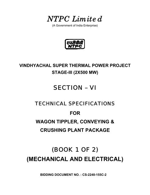
<strong>NTPC</strong> <strong>Limited</strong><br />
(A Government of India Enterprise)<br />
VINDHYACHAL SUPER THERMAL POWER PROJECT<br />
STAGE-III (2X500 MW)<br />
SECTION – VI<br />
TECHNICAL SPECIFICATIONS<br />
FOR<br />
WAGON TIPPLER, CONVEYING &<br />
CRUSHING PLANT PACKAGE<br />
(BOOK 1 OF 2)<br />
(MECHANICAL AND ELECTRICAL)<br />
BIDDING DOCUMENT NO. : CS-2240-155C-2
<strong>NTPC</strong> <strong>Limited</strong><br />
(A Government of India Enterprise)<br />
VINDHYACHAL SUPER THERMAL POWER PROJECT<br />
STAGE-III (2X500 MW)<br />
SECTION – VI<br />
TECHNICAL SPECIFICATIONS<br />
FOR<br />
WAGON TIPPLER, CONVEYING &<br />
CRUSHING PLANT PACKAGE<br />
(BOOK 1 OF 2)<br />
(MECHANICAL AND ELECTRICAL)<br />
BIDDING DOCUMENT NO. : CS-2240-155C-2<br />
(This document is meant for the exclusive purpose of bidding against this Bid<br />
Document No. / Specification and shall not be transferred, reproduced or<br />
otherwise used for purposes other than that for which it is specifically issued).
VINDHYACHAL SUPER THERMAL POWER<br />
PROJECT, STAGE-III (2X500 MW)<br />
WAGON TIPPLER, CONVEYING & CRUSHING<br />
PLANT PACKAGE<br />
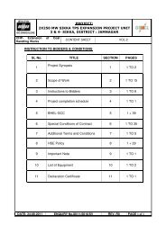
TABLE OF CONTENTS<br />
TABLE OF CONTENTS<br />
PART SECTION NO TITLE<br />
BOOK 1 OF 2 : MECHANICAL & ELECTRICAL<br />
PART-A Sub Section- I Project Synopsis<br />
PART-A<br />
Sub Section – II : Scope of Supply & Services<br />
IIA-01<br />
Intent of Specification<br />
Scope<br />
Terminal Points & Exclusions<br />
IIB-01 PG Test Procedure<br />
IIC-01 Spares<br />
PART-B Sub Section III : Technical Parameters<br />
PART-B<br />
III-A MECHANICAL<br />
IIIA-01 System Parameters and Operation & Control<br />
Philosophy<br />
IIIA-02 Wagon Tippler<br />
IIIA-03 Brakes & Clamps<br />
IIIA-04 Monorails and Hoists<br />
IIIA-05 Chutes & Hoppers<br />
IIIA-06 Belt Conveyor System<br />
IIIA-07 Drive Equipment<br />
IIIA-08 Belt Scale<br />
IIIA-09 Dust Control & Miscellaneous System<br />
IIIA-10 Ventilation System<br />
IIIA-11 CHP Building<br />
IIIA-12 Vibrating Screening Feeder<br />
IIIA-13 Ring Granulator and VMS<br />
TECHNICAL SPECIFICATIONS<br />
SECTION-VI<br />
MAIN CONTENTS<br />
PAGE 1 OF 3
VINDHYACHAL SUPER THERMAL POWER<br />
PROJECT, STAGE-III (2X500 MW)<br />
WAGON TIPPLER, CONVEYING & CRUSHING<br />
PLANT PACKAGE<br />
TABLE OF CONTENTS<br />
PART SECTION NO TITLE<br />
IIIA-14 Inline Magnetic Separator and Suspended<br />
Magnet<br />
IIIA-15 Metal Detector<br />
IIIA-16 Coal Sampling Unit<br />
IIIA-17 Elevator<br />
IIIA-18 Apron Feeder<br />
IIIA-19 Side Arm Charger<br />
PART-B III-B ELECTRICAL<br />
PART-B<br />
IIIB-01 Motors<br />
IIIB-02 LT Switchgear & Bus Duct<br />
IIIB-03 HT Cables<br />
IIIB-04 LT Power Cables<br />
IIIB-05 Control Cables<br />
IIIB-06 Instrumentation cables<br />
IIIB-07 Illumination System<br />
IIIB-08 Cabling, Earthing & Lightning Protection<br />
IIIB-09 Transformers<br />
IIIB-10 HT Switchgear<br />
IIIB-11 Battery<br />
IIIB-12 Battery Charger<br />
IIIB-13 Control Panel<br />
IIIB-14 Closed Circuit Television System (CCTV)<br />
BOOK 2 OF 2 : CIVIL / QA&I / GTR / ECC / SPARES<br />
PART-B III-D CIVIL<br />
PART-B IIID-01 CHP System - Civil & Structural Works<br />
TECHNICAL SPECIFICATIONS<br />
SECTION-VI<br />
MAIN CONTENTS<br />
PAGE 2 OF 3
VINDHYACHAL SUPER THERMAL POWER<br />
PROJECT, STAGE-III (2X500 MW)<br />
WAGON TIPPLER, CONVEYING & CRUSHING<br />
PLANT PACKAGE<br />
TABLE OF CONTENTS<br />
PART SECTION NO TITLE<br />
IIID-02 Foundation System and Geotechnical Data<br />
(Turnkey)<br />
PART-B III-E QA & I SECTION<br />
PART-B<br />
IIIE-01 Coal Handling Plant<br />
IIIE-02 Motors<br />
IIIE-03 LT Switchgear & Busduct<br />
IIIE-04 LT Power Cables<br />
IIIE-05 LT Control Cables<br />
IIIE-06 Instrumentation Cables<br />
IIIE-07 Station Lighting<br />
IIIE-08 Cabling, Earthing & Lightning Protection<br />
IIIE-09 Control Panels<br />
IIIE-10 Programmable Logic Controller (PLC)<br />
IIIE-11 Battery Charger<br />
IIIE-12 HT Cables<br />
IIIE-13 HT Switchgear<br />
IIIE-14 Actuators<br />
IIIE-15 Auxiliary Transformer<br />
IIIE-16 Battery & Battery System<br />
IIIE-17 Measuring & Instrumentation<br />
IIIE-18 Closed Circuit Television System (CCTV)<br />
IIIE-19 CHP System - Civil & Structural Works<br />
PART-C General Technical Requirements<br />
PART-D Erection Conditions of Contract<br />
PART-E List of Tender Drawings<br />
PART-F List of Mandatory Spares<br />
TECHNICAL SPECIFICATIONS<br />
SECTION-VI<br />
MAIN CONTENTS<br />
PAGE 3 OF 3
VINDHYACHAL SUPER THERMAL POWER PROJECT,<br />
STAGE-III (2X500 MW)<br />
WAGON TIPPLER, CONVEYING & CRUSHING<br />
PLANT PACKAGE<br />
PART - A<br />
TECHNICAL SPECIFICATIONS<br />
SECTION-VI<br />
PART-A
VINDHYACHAL SUPER THERMAL POWER PROJECT,<br />
STAGE-III (2X500 MW)<br />
WAGON TIPPLER, CONVEYING & CRUSHING<br />
PLANT PACKAGE<br />
PART - A<br />
SUB-SECTION-I<br />
PROJECT SYNOPSIS<br />
TECHNICAL SPECIFICATIONS<br />
SECTION-VI<br />
PART-A
CLAUSE NO.<br />
1.00.00 BACKGROUND<br />
VINDHYACHAL SUPER THERMAL POWER<br />
PROJECT, STAGE-III (2X500 MW)<br />
WAGON TIPPLER, CONVEYING & CRUSHING<br />
PLANT PACKAGE<br />
PROJECT SYNOPSIS<br />
PROJECT SYNOPSIS<br />
Details of proposed Stage / Units<br />
Project name Vindhyachal STPP<br />
Project Stage Wagon Tippler, Conveying & Crushing System<br />
No. of Units x capacity Applicable for Stage-I (6x210 MW), Stage-II<br />
Project setting up by <strong>NTPC</strong> Ltd.<br />
Details of Existing Units :<br />
Stage-1:<br />
Stage-2:<br />
Stage-3:<br />
2.00.00 LOCATION AND APPROACH<br />
(2X500 MW) and for Stage-III (2X500 MW)<br />
No. of units. : 6 Capacity : 210 MW<br />
Present Status : Units Commissioned<br />
No. of units. : 2 Capacity : 500 MW<br />
Present Status : Units Commissioned<br />
No. of units. : 2 Capacity : 500 MW<br />
Present Status : Units Commissioned<br />
Project Location (i.) Place :Vindhyachal<br />
Latitude and Longitude<br />
of project location<br />
(ii) District :Sidhi<br />
TECHNICAL SPECIFICATIONS<br />
SECTION-VI<br />
PART-A<br />
(iii.) State :Madhya Pradesh<br />
North : 24 Deg 06' N<br />
East : 82 Deg 40' E<br />
Nearest Railway station Shakti Nagar<br />
Distance of project location from<br />
the Railway station<br />
2 KM (Approx.)<br />
SUB-SECTION-I<br />
PROJECT SYNOPSIS<br />
PAGE<br />
1 OF 17
CLAUSE NO.<br />
3.00.00 WATER<br />
VINDHYACHAL SUPER THERMAL POWER<br />
PROJECT, STAGE-III (2X500 MW)<br />
WAGON TIPPLER, CONVEYING & CRUSHING<br />
PLANT PACKAGE<br />
PROJECT SYNOPSIS<br />
Nearest Major Town Renukoot<br />
Distance of the town from the<br />
Project site<br />
50 KM<br />
Nearest Commercial Airport Varanasi<br />
Distance of airport from the<br />
project site<br />
220 KM<br />
Nearest Highway State Highway<br />
Distance from nearest highway<br />
point to the site<br />
2KM (aprox.)<br />
Vicinity plan Vicinity plan of the project<br />
Any other information: Further to the information given in this subsection<br />
, Bidders are advised to visit the<br />
project site and collect data on local site<br />
conditions<br />
Nearest Water Source Hot water discharge channel of Singrauli<br />
Water requirement for the<br />
ultimate Stage (all the three<br />
stages)<br />
Proposed source/<br />
arrangement to meet the<br />
water requirement :<br />
230Cusec<br />
Hot water discharge channel of Singrauli<br />
4.00.00 COAL LINKAGE/AVAILABILITY AND TRANSPORTATION<br />
(a.) Coal Linkage/Availability<br />
Proposed source/<br />
arrangement to meet the<br />
coal requirement :<br />
Coal Commitment/ Coal<br />
Link<br />
TECHNICAL SPECIFICATIONS<br />
SECTION-VI<br />
PART-A<br />
MCL, CCL and Import tie-ups<br />
The SLC granted linkage of 3.00 million tons<br />
per annum from MCL, CCL and Import tie-ups<br />
through Indian Railway System.<br />
SUB-SECTION-I<br />
PROJECT SYNOPSIS<br />
PAGE<br />
2 OF 17
CLAUSE NO.<br />
VINDHYACHAL SUPER THERMAL POWER<br />
PROJECT, STAGE-III (2X500 MW)<br />
WAGON TIPPLER, CONVEYING & CRUSHING<br />
PLANT PACKAGE<br />
PROJECT SYNOPSIS<br />
TECHNICAL SPECIFICATIONS<br />
SECTION-VI<br />
PART-A<br />
The SLC granted linkage of 9.9 million tons<br />
per annum from NCL through MGR System.<br />
Any other information: Coal Requirement for Vindhyachal STPP<br />
Stage I, II & III is also being met from same<br />
coal source.<br />
(b.) Coal Transportation<br />
Existing coal transportation<br />
arrangement<br />
Proposed Coal<br />
transportation arrangement<br />
Captive MGR system<br />
: Through Indian Railway System by laying<br />
additional track.<br />
(c.) Coal Quality Parameters and Fuel Oil Characteristics<br />
The Coal quality Parameters and Fuel Oil Characteristics are enclosed as<br />
Annexures to this subsection.<br />
5.00.00 METEOROLOGICAL DATA<br />
Data of Sidhi station is enclosed as Annexure to this subsection.<br />
6.00.00 PLANT WATER SCHEME<br />
6.01.00 Condenser Cooling (CW) Water System<br />
It is proposed to provide recirculating type CW system with induced draft type cooling<br />
towers. Raw water for Stage - III of this project shall be pumped from the hot water<br />
(CW system) discharge channel of Singrauli Project of <strong>NTPC</strong> to Water Pretreatment<br />
Plant. The treated clarified water shall be pumped to the CW channels of Stage - III<br />
Circulating Water (CW) system at the upstream of cooling towers as make up to the<br />
system. It is proposed to operate the CW system at a C.O.C. of about 2.5 and CW<br />
side stream filtration and chemical treatment programme (using acid dosing and<br />
scale cum corrosion inhibitors dosing) shall be employed in addition to blow down of<br />
CW water to control the CW system water chemistry. The expected circulating water<br />
analysis is given in Annexure A-III of this sub-section. The CW blow water shall be<br />
tapped off from the discharge of CW pumps and led to a Service Water Tank.<br />
6.02.00 Equipment Cooling Water (ECW) System (Unit & Station Auxiliaries)<br />
The plant auxiliaries of Steam Generator and Turbine Generator shall be cooled by<br />
Demineralised water (DM) in a closed circuit. The primary circuit DM water shall be<br />
cooled through plate type heat exchangers by Circulating Water tapped from CW<br />
SUB-SECTION-I<br />
PROJECT SYNOPSIS<br />
PAGE<br />
3 OF 17
CLAUSE NO.<br />
VINDHYACHAL SUPER THERMAL POWER<br />
PROJECT, STAGE-III (2X500 MW)<br />
WAGON TIPPLER, CONVEYING & CRUSHING<br />
PLANT PACKAGE<br />
PROJECT SYNOPSIS<br />
system in a closed secondary circuit The hot secondary circuit cooling water shall be<br />
cooled in the cooling towers and shall be returned back to the system.<br />
7.00.00 ASH WATER SYSTEM<br />
It is proposed to operate the ash water system in a closed circuit at a C.O.C. of about<br />
2.5. The ash water from the ash dyke shall be re-used after treating a part of the<br />
same in a side stream lime softening plant. During re-circulation mode, the make up<br />
to the ash water system (to compensate for the ash water blow down and<br />
evaporation loss) shall be supplied from the CW system blow down water.<br />
During initial operating stage of the project, when decanted ash water is not available<br />
from the dyke, the ash water system shall be operated in once through mode. The<br />
make-up water to ash water system shall be pumped from the raw water (from the<br />
discharge channel of Singrauli station) source, CW blow down water from the Service<br />
water tank and as well as from treated water from Central Monitoring Basin of liquid<br />
Effluent Treatment Plant.<br />
Considering total ash handling plant water requirement of 2500 Cu.M/hr for slurry<br />
formation during re-circulation mode operation, it is expected that about 2000 M3/hr<br />
of decanted ash water shall return to the ash handling system after accounting for<br />
evaporation loss. Considering a system blow down of about 350 Cu.M/hr from the<br />
system, raw water make up of 850 M3/hr shall be pumped from the service water<br />
tank which shall be CW blow down quality. About 30% of decanted ash water shall<br />
be treated in a side stream lime softening plant bay and treated water be led to ash<br />
water system.<br />
During once through mode operation, about 1000 M3/hr shall be pumped from the<br />
service water tank (CW system blow down quality) and balance 1500 M3/hr water<br />
shall be pumped from the raw water source (hot water discharge channel).<br />
8.00.00 OTHER MISCELLANEOUS WATER SYSTEMS<br />
(a.) CW system blow down water shall be used for the plant service water<br />
requirement, Wash water for Air-preheaters and ESPs, dust suppression<br />
system of coal handling plant, make-up to fire water storage tanks and<br />
cooling water requirement of hydrogen generation plant. CW blow down water<br />
is estimated to be of the order of 1500 Cu.M/hr.<br />
(b.) The drinking water requirement shall be provided from the above mentioned<br />
Water pretreatment plant.<br />
(c.) It is proposed to provide two numbers of DM water storage tanks for Stage-III<br />
and these new sets of tanks shall be filled by extension of existing DM water<br />
pipelines of Stage-II. From the proposed DM water Storage tanks, DM water<br />
shall be pumped to meet the Steam Cycle make-up water requirement,<br />
makeup the hydrogen generation plant and makeup to the primary circuit of<br />
TECHNICAL SPECIFICATIONS<br />
SECTION-VI<br />
PART-A<br />
SUB-SECTION-I<br />
PROJECT SYNOPSIS<br />
PAGE<br />
4 OF 17
CLAUSE NO.<br />
VINDHYACHAL SUPER THERMAL POWER<br />
PROJECT, STAGE-III (2X500 MW)<br />
WAGON TIPPLER, CONVEYING & CRUSHING<br />
PLANT PACKAGE<br />
PROJECT SYNOPSIS<br />
ECW system of unit auxiliaries by means of DM water make up pumps. In<br />
addition, separate set of boiler fill pumps shall be provided to fill the boiler<br />
from these DM water storage tank. DM Water required for regeneration of<br />
Condensate polishing Plant and resin transfer operation shall also be<br />
provided by these tanks.<br />
(d.) The service (wash water) collected from various areas shall be treated using<br />
oil water separators, tube settlers, coal settling pits etc. as per requirement<br />
and treated water from liquid effluent treatment plant shall be recycled back to<br />
the service water system for re-use. The excess service water from the<br />
service water tank/CW blow down pipe line shall be led to central monitoring<br />
basin for disposal.<br />
(e.) The quality of Clarified water, filtered (potable) water and DM water is given in<br />
the enclosed Annexure to this sub-section.<br />
9.00.00 CRITERIA FOR WIND RESISTANT DESIGN OF STRUCTURES AND EQUIPMENT<br />
All structures and equipment of the power plant, including plant auxiliary structures<br />
and equipment, shall be designed for wind forces as given in the Technical<br />
Specification on Civil Works.<br />
10.00.00 CRITERIA FOR EARTHQUAKE RESISTANT DESIGN OF STRUCTURES AND<br />
EQUIPMENT<br />
All power plant structures and equipment, including plant auxiliary structures and<br />
equipment shall be designed for seismic forces as given in the Technical<br />
Specification on Civil Works.<br />
TECHNICAL SPECIFICATIONS<br />
SECTION-VI<br />
PART-A<br />
SUB-SECTION-I<br />
PROJECT SYNOPSIS<br />
PAGE<br />
5 OF 17
CLAUSE NO.<br />
Sl.<br />
No.<br />
VINDHYACHAL SUPER THERMAL POWER<br />
PROJECT, STAGE-III (2X500 MW)<br />
WAGON TIPPLER, CONVEYING & CRUSHING<br />
PLANT PACKAGE<br />
PROJECT SYNOPSIS<br />
COAL QUALITY PARAMETERS ANNEXURE –A- II -1<br />
Description Unit Design<br />
Coal<br />
TECHNICAL SPECIFICATIONS<br />
SECTION-VI<br />
PART-A<br />
Range of 95%<br />
coal Supplies<br />
Worst<br />
Coal<br />
Best<br />
Coal<br />
1 2 3 4 5 6 7<br />
A. PROXIMATE ANALYSIS (As received basis)<br />
SUB-SECTION-I<br />
PROJECT SYNOPSIS<br />
Range of<br />
Adequacy<br />
1. Total Moisture % 20.00 22.00 17.00 23 - 16<br />
2. Ash % 30.00 35.00 24.00 36 - 23<br />
3. Volatile matter % 21.00 19.00 23.00 18 - 24<br />
4. Fixed carbon % 29.00 24.00 36.00 23 - 37<br />
B. ULTIMATE ANALYSIS (As received basis)<br />
1. Carbon C% 37.56 32.30 45.00 30.4 - 46.90<br />
2. Hydrogen H2% 3.2 2.9 3.5 2.8 - 3.6<br />
3. Nitrogen N2% 0.95 0.55 1.6 0.55 - 1.6<br />
4. Oxygen O2% 6.94 6.25 7.06 6.25 - 7.06<br />
5. Sulphur S% 0.3 0.3 0.5 0.3 - 0.5<br />
6. Carbonates CO3% 0.75 0.6 0.92 0.6 - 0.92<br />
7. Phosphorous P2% 0.3 0.1 0.42 0.1 - 0.42<br />
8. Total Moisture H2O% 20 22 17 23 - 16<br />
9. Ash % 30 35 24 36 - 23<br />
10. Total % 100 100 100<br />
11. Gross Calorific<br />
Value<br />
KCal/Kg 3700 3200 4400 3000 - 4500<br />
12. Hard grove index 52 48 60 48 – 62<br />
13. YGP index<br />
(minimum)<br />
mg/kg 80 80 80 80<br />
PAGE<br />
6 OF 17
CLAUSE NO.<br />
Sl.<br />
No.<br />
VINDHYACHAL SUPER THERMAL POWER<br />
PROJECT, STAGE-III (2X500 MW)<br />
WAGON TIPPLER, CONVEYING & CRUSHING<br />
PLANT PACKAGE<br />
PROJECT SYNOPSIS<br />
COAL QUALITY PARAMETERS ANNEXURE –A- II -1<br />
Description Unit Design<br />
Coal<br />
TECHNICAL SPECIFICATIONS<br />
SECTION-VI<br />
PART-A<br />
Range of 95%<br />
coal Supplies<br />
Worst<br />
Coal<br />
Best<br />
Coal<br />
1 2 3 4 5 6 7<br />
C. ASH ANALYSIS<br />
SUB-SECTION-I<br />
PROJECT SYNOPSIS<br />
Range of<br />
Adequacy<br />
1. Silica (SiO2)% 59.6 58.6 62.5 58.1 – 63.0<br />
2. Alumina (Al2O3)% 24.6 25.6 22.7 26.1 - 22.2<br />
3. Iron Oxide (Fe2O3)% 10.2 11.2 8.62 11.5-8.32<br />
4. Titania (TiO2)% 1.07 1.17 0.80 1.2 – 0.82<br />
5. Phosphoric<br />
Anhydride<br />
(P2O5)% 0.18 0.1 0.48 0.1 - 0.5<br />
6. Lime (CaO)% 3.2 2.08 3.3 1.78 – 3.5<br />
7. Magnesia (MgO)% 0.6 0.9 0.5 0.9 – 0.5<br />
8. Sulphuric<br />
Anhydride<br />
9. Alkalies<br />
(By diff.)<br />
(SO3)% 0.25 0.15 0.4 0.12 - 0.43<br />
Na2O +<br />
K2O%<br />
D. ASH FUSION RANGE (Under reducing atmosphere)<br />
a) Initial<br />
Deformation<br />
Temperature<br />
b) Hemispherical<br />
temperature<br />
c) Fusion<br />
temperature<br />
0.3 0.2 0.7 0.2 – 0.73<br />
(IDT) °C 1110 1050 1150 1000 - 1150<br />
°C 1300 1250 1350 1200 - 1400<br />
°C 1400 1400 1400 1400-1450<br />
PAGE<br />
7 OF 17
CLAUSE NO.<br />
Sl.<br />
No.<br />
VINDHYACHAL SUPER THERMAL POWER<br />
PROJECT, STAGE-III (2X500 MW)<br />
WAGON TIPPLER, CONVEYING & CRUSHING<br />
PLANT PACKAGE<br />
PROJECT SYNOPSIS<br />
COAL QUALITY PARAMETERS ANNEXURE –A- II -1<br />
Description Unit Design<br />
Coal<br />
TECHNICAL SPECIFICATIONS<br />
SECTION-VI<br />
PART-A<br />
Range of 95%<br />
coal Supplies<br />
Worst<br />
Coal<br />
Best<br />
Coal<br />
1 2 3 4 5 6 7<br />
E. ASH FUSION RANGE (Under oxidising atmosphere)<br />
a) Initial<br />
Deformation<br />
Temperature<br />
b) Hemispherical<br />
temperature<br />
c) Fusion<br />
temperature<br />
SUB-SECTION-I<br />
PROJECT SYNOPSIS<br />
Range of<br />
Adequacy<br />
(IDT) °C 1200 1100 1250 1050 - 1250<br />
°C 1350 1300 1400 1250 - 1400<br />
°C 1400 1400 1400 1400-1450<br />
PAGE<br />
8 OF 17
CLAUSE NO.<br />
FUEL OIL CHARACTERISTICS<br />
Sl.<br />
No.<br />
VINDHYACHAL SUPER THERMAL POWER<br />
PROJECT, STAGE-III (2X500 MW)<br />
WAGON TIPPLER, CONVEYING & CRUSHING<br />
PLANT PACKAGE<br />
PROJECT SYNOPSIS<br />
Characteristics Heavy<br />
Furnace Oil<br />
IS-1593 1971<br />
Grade HV<br />
TECHNICAL SPECIFICATIONS<br />
SECTION-VI<br />
PART-A<br />
Low Sulphur<br />
Oil Heavy<br />
Stock (LSHS)<br />
SUB-SECTION-I<br />
PROJECT SYNOPSIS<br />
ANNEXURE A – II- 2<br />
(Sheet 1 of 2)<br />
Heavy<br />
Petroleum<br />
Stock (HPS)<br />
1. Total sulphur content 4.5% Max. 1.0% Max 4.5% Max.<br />
2. Gross calorific<br />
alue(KCal/kg)<br />
3. Flash Point (Min)<br />
(PMCC)<br />
4. Water content by<br />
volume (Max)<br />
5. Sediment by weight<br />
(Max)<br />
6. Asphaltene content by<br />
weight (Max.)<br />
7. Kinematic viscosity in<br />
Centistokes 50deg C<br />
(Max)<br />
8. Ash Content by weight<br />
(Max.)<br />
10280<br />
(Typical)<br />
Of the<br />
orderof11,000<br />
Of the orderof<br />
10,000<br />
66 deg C 76 deg C 66-76 deg C<br />
1.0% 1.0% 1.0%<br />
0.25% 0.25% 0.25%<br />
- - -<br />
370 - -<br />
0.1% 0.05% 0.1%<br />
9. Acidity (inorganic) Nil Nil Nil<br />
10. Pour Point (Max.)<br />
72Deg.C<br />
- - 72 deg C<br />
11. Sodium content - - -<br />
12. Vanadium content - - -<br />
13. Specific heat below<br />
pour point (KCal/Kg °C)<br />
- - -<br />
PAGE<br />
9 OF 17
CLAUSE NO.<br />
VINDHYACHAL SUPER THERMAL POWER<br />
PROJECT, STAGE-III (2X500 MW)<br />
WAGON TIPPLER, CONVEYING & CRUSHING<br />
PLANT PACKAGE<br />
PROJECT SYNOPSIS<br />
LIGHT OIL CHARACTERISTICS<br />
(AS PER IS 1460-1974 WITH AMENDMENTS UPTO OCT.85)<br />
S.No. Characteristics LDO<br />
TECHNICAL SPECIFICATIONS<br />
SECTION-VI<br />
PART-A<br />
SUB-SECTION-I<br />
PROJECT SYNOPSIS<br />
ANNEXURE-A-II-2<br />
(Sheet 2 of 2)<br />
1. Pour Point (max) 12 deg. C & 21 deg C for<br />
Winter and summer<br />
respectively.<br />
2. Kinematic viscosity in centistokes at 38<br />
deg.C<br />
3. Waste content, percent by volume (max) 0.25<br />
4. Sediment percent by mass (max) 0.10<br />
5. Total sulphur percent by mass (max) 1.8<br />
6. Ash percentage by mass (max) 0.02<br />
7. Carbon residue (Rans bottom) percent by<br />
pass (max.)<br />
8. Acidity in organic Nil<br />
9. Flash point (Min.)<br />
a) Abel ° C, min<br />
b) PMCC O C, min.<br />
10. Acidity, total, mg of KOH/g (max.) -<br />
2.5 to 15.7<br />
1.50<br />
11. Copper strip corrosion for 3 hours at 100°C Not worse than No.2<br />
12. Total sediment mg per 100 ml max. = 1.0 Not worse than No.2<br />
-<br />
66<br />
PAGE<br />
10 OF 17
CLAUSE NO.<br />
VINDHYACHAL SUPER THERMAL POWER<br />
PROJECT, STAGE-III (2X500 MW)<br />
WAGON TIPPLER, CONVEYING & CRUSHING<br />
PLANT PACKAGE<br />
PROJECT SYNOPSIS<br />
WATER ANALYSIS<br />
Sl. No. Constituent as mg per litre<br />
a) COOLING WATER ANALYSIS<br />
1. Calcium CaCO 3 148.0<br />
2. Magnesium CaCO 3 37.5<br />
3. Sodium & Potassium CaCO 3 47.5<br />
4. Bicarbonates CaCO 3 104.5<br />
5. Chloride CaCO 3 47.5<br />
6. Sulphate CaCO 3 81.0<br />
7. Carbonate CaCO 3 0<br />
8. Silica SiO2 25.0<br />
9. Iron Fe 0.75<br />
10. pH Value - 7.6 - 7.9<br />
11. Turbidity NTU 50<br />
TECHNICAL SPECIFICATIONS<br />
SECTION-VI<br />
PART-A<br />
SUB-SECTION-I<br />
PROJECT SYNOPSIS<br />
ANNEXURE- A-IV<br />
Note : The C.W system is expected to operate at about 2.5 Cycles of<br />
Concentration.<br />
b) RAW WATER (MAKEUP TO ASH WATER SYSTEM) ANALYSIS<br />
1. Calcium CaCO 3 34.0<br />
2. Magnesium CaCO 3 15.0<br />
3. Sodium & Potassium CaCO 3 19.0<br />
4. Bicarbonates CaCO 3 46.0<br />
5. Chloride CaCO 3 12.0<br />
PAGE<br />
11 OF 17
CLAUSE NO.<br />
VINDHYACHAL SUPER THERMAL POWER<br />
PROJECT, STAGE-III (2X500 MW)<br />
WAGON TIPPLER, CONVEYING & CRUSHING<br />
PLANT PACKAGE<br />
PROJECT SYNOPSIS<br />
WATER ANALYSIS<br />
Sl. No. Constituent as mg per litre<br />
6. Sulphate CaCO 3 10.0<br />
7. Carbonate CaCO 3 0<br />
8. Silica SiO2 10.0<br />
9. Iron Fe 2.0<br />
10. pH Value - 7.6 - 8.2<br />
11. Turbidity NTU 50 -500<br />
12.<br />
Temperature ( o C)<br />
Note : Raw water from hot water channel of Singrauli STPP.<br />
c) CLARIFIED WATER ANALYSIS (PT-CW)<br />
1. Calcium CaCO 3 59.2<br />
2. Magnesium CaCO 3 15.0<br />
3. Sodium & Potassium CaCO 3 19.0<br />
4. Bicarbonates CaCO 3 41.7<br />
5. Chloride CaCO 3 19.0<br />
6. Sulphate CaCO 3 32.5<br />
7. . Carbonate CaCO 3 0<br />
8. Silica SiO2 10.0<br />
9. Iron Fe 2.0<br />
10. pH Value - 7.6 – 8.2<br />
11. Turbidity NTU 50 - 500<br />
12.<br />
Temperature ( o C)<br />
Note : At the outlet of clarifier of PT plant<br />
TECHNICAL SPECIFICATIONS<br />
SECTION-VI<br />
PART-A<br />
43<br />
43<br />
SUB-SECTION-I<br />
PROJECT SYNOPSIS<br />
ANNEXURE- A-IV<br />
PAGE<br />
12 OF 17
CLAUSE NO.<br />
VINDHYACHAL SUPER THERMAL POWER<br />
PROJECT, STAGE-III (2X500 MW)<br />
WAGON TIPPLER, CONVEYING & CRUSHING<br />
PLANT PACKAGE<br />
PROJECT SYNOPSIS<br />
WATER ANALYSIS<br />
Sl. No. Constituent as mg per litre<br />
d) FILTERED WATER ANALYSIS (Drinking Water)<br />
1. Calcium CaCO 3 59.2<br />
2. Magnesium CaCO 3 15.0<br />
3. Sodium & Potassium CaCO 3 19.0<br />
4. Bicarbonates CaCO 3 41.7<br />
5. Chloride CaCO 3 19.0<br />
6. Sulphate CaCO 3 32.5<br />
7. Carbonate CaCO 3 0<br />
8. Silica SiO2 10.0<br />
9. Iron Fe 0.30<br />
10. pH Value - 7.5 – 7.7<br />
11. Turbidity NTU 2<br />
TECHNICAL SPECIFICATIONS<br />
SECTION-VI<br />
PART-A<br />
SUB-SECTION-I<br />
PROJECT SYNOPSIS<br />
ANNEXURE- A-IV<br />
PAGE<br />
13 OF 17
CLAUSE NO.<br />
VINDHYACHAL SUPER THERMAL POWER<br />
PROJECT, STAGE-III (2X500 MW)<br />
WAGON TIPPLER, CONVEYING & CRUSHING<br />
PLANT PACKAGE<br />
PROJECT SYNOPSIS<br />
ANALYSIS OF DM WATER TO BE USED FOR<br />
MAKE-UP WATER TO CONDENSER<br />
Sl. No. Characteristics Value<br />
1. Silica (Max.) 0.02 ppm as SiO2<br />
2. Iron as Fe Nil<br />
3. Total hardness Nil<br />
4. pH value 6.8 to 7.2<br />
TECHNICAL SPECIFICATIONS<br />
SECTION-VI<br />
PART-A<br />
SUB-SECTION-I<br />
PROJECT SYNOPSIS<br />
ANNEXURE-A-IV<br />
5. Conductivity Not more than 0.1 excluding<br />
the effects of free CO 2<br />
PAGE<br />
14 OF 17
CLAUSE NO.<br />
VINDHYACHAL SUPER THERMAL POWER<br />
PROJECT, STAGE-III (2X500 MW)<br />
WAGON TIPPLER, CONVEYING & CRUSHING<br />
PLANT PACKAGE<br />
PROJECT SYNOPSIS<br />
TECHNICAL SPECIFICATIONS<br />
SECTION-VI<br />
PART-A<br />
SUB-SECTION-I<br />
PROJECT SYNOPSIS<br />
VICINITY PLAN<br />
PAGE<br />
15 OF 17
CLAUSE NO.<br />
VINDHYACHAL SUPER THERMAL POWER<br />
PROJECT, STAGE-III (2X500 MW)<br />
WAGON TIPPLER, CONVEYING & CRUSHING<br />
PLANT PACKAGE<br />
PROJECT SYNOPSIS<br />
METEOROLOGICAL DATA<br />
TECHNICAL SPECIFICATIONS<br />
SECTION-VI<br />
PART-A<br />
SUB-SECTION-I<br />
PROJECT SYNOPSIS<br />
PAGE 1 OF 2<br />
PAGE<br />
16 OF 17
CLAUSE NO.<br />
VINDHYACHAL SUPER THERMAL POWER<br />
PROJECT, STAGE-III (2X500 MW)<br />
WAGON TIPPLER, CONVEYING & CRUSHING<br />
PLANT PACKAGE<br />
PROJECT SYNOPSIS<br />
TECHNICAL SPECIFICATIONS<br />
SECTION-VI<br />
PART-A<br />
SUB-SECTION-I<br />
PROJECT SYNOPSIS<br />
PAGE 2 OF 2<br />
PAGE<br />
17 OF 17
VINDHYACHAL SUPER THERMAL POWER PROJECT,<br />
STAGE-III (2X500 MW)<br />
WAGON TIPPLER, CONVEYING & CRUSHING<br />
PLANT PACKAGE<br />
PART - A<br />
SUB-SECTION-IIA-01<br />
SCOPE OF SUPPLY & SERVICES<br />
TECHNICAL SPECIFICATIONS<br />
SECTION-VI<br />
PART-A
CLAUSE NO.<br />
VINDHYACHAL SUPER THERMAL POWER<br />
PROJECT, STAGE-III (2X500 MW)<br />
WAGON TIPPLER, CONVEYING & CRUSHING<br />
PLANT PACKAGE<br />
SCOPE OF SUPPLY & SERVICES<br />
COAL HANDLING PLANT :<br />
WAGON TIPPLER, CONVEYING & CRUSHING PLANT<br />
1.00.00 INTENT OF SPECIFICATION<br />
1.01.00 This specification is intended to cover the following activities and services in respect<br />
of all the equipment of CHP - Wagon Tippler, Conveying & Crushing Plant to be<br />
installed for Vindhyachal Super Thermal Power Project of the National Thermal<br />
Power Corporation Ltd.), completely covering the following activities and services in<br />
respect of all the equipment specified and covered under the specifications and read<br />
in conjunction with “Scope of Supply & Services”, Sub-section-III, Part-A, Section–VI<br />
of Technical Specification.<br />
(a.) (i) Detailed design and engineering of all the equipment and equipment<br />
system(s).<br />
(ii) Complete manufacture including shop testing/ type testing.<br />
(iii) Providing engineering data, drawings, Commissioning procedures and<br />
O & M manuals, etc. for the Employer’s review, approval and records.<br />
(iv) Packing and transportation from the manufacturer’s works to site<br />
including customs clearance/ port clearance, if required.<br />
(v) Receipt, unloading, storage, preservation conservation and insurance<br />
of equipment at site.<br />
(vi) Fabrication, pre-assembly, (if any), erection, testing and putting into<br />
satisfactory operation of all the equipment including successful<br />
completion of facilities.<br />
(vii) Associated civil, structural, architectural and electrical works.<br />
(viii) Commissioning and completion of facilities and Performance<br />
Guarantee Tests.<br />
(ix) Furnishing of spares on FOR site basis and handing over to <strong>NTPC</strong><br />
stores.<br />
(x) Reconciliation with custom authorities, if applicable.<br />
(xi) Satisfactory conclusion of the contract.<br />
TECHNICAL SPECIFICATIONS<br />
SECTION-VI<br />
PART-A<br />
SUB-SECTION-IIA-01<br />
SCOPE OF SUPPLY &<br />
SERVICES<br />
PAGE<br />
1 OF 21
CLAUSE NO.<br />
VINDHYACHAL SUPER THERMAL POWER<br />
PROJECT, STAGE-III (2X500 MW)<br />
WAGON TIPPLER, CONVEYING & CRUSHING<br />
PLANT PACKAGE<br />
SCOPE OF SUPPLY & SERVICES<br />
(b.) The equipment and services to be furnished and erected as required in this<br />
Technical Specification shall also meet all the requirements as stated<br />
“General Conditions of Contract” (GCC), “ Special Conditions of Contract”<br />
(SCC) and “Bid Form & Procedures” which shall be considered as a part of<br />
this technical specification as bound herewith.<br />
(c.) The Contractor shall be responsible for providing all materials, equipment and<br />
services, specified or otherwise (unless specifically excluded) which are<br />
required to fulfill the intent of ensuring operability and the reliability of the<br />
complete system covered under this specification.<br />
(d.) It is not the intent to specify completely herein, all aspects of design and<br />
construction of equipment. Nevertheless, the equipment shall conform in all<br />
respects to high standards of engineering, design and workmanship and shall<br />
be capable of performing in continuous commercial operation.<br />
(e.) Whenever a material or article is specified or described by the name of a<br />
particular brand, manufacturer or trade mark, the specific item shall be<br />
understood as establishing type, function and quality desired. Other<br />
manufacturer’s products may also be considered provided sufficient<br />
information is furnished so as to enable the Employer to determine that the<br />
products are equivalent or superior to those named.<br />
(f.) Contractor is requested to carefully examine and understand the<br />
specifications and seek clarifications, if required, to ensure that they have<br />
understood the specifications. Such clarifications should reach Employer at<br />
least 15 days before the scheduled date of the opening of the bid documents.<br />
The Contractor’s offer should not carry any sections like clarifications,<br />
interpretations and/or assumptions.<br />
(g.) If the Contractor feels that, in his opinion, certain features brought out in his<br />
offer are superior to what has been specified, those may be highlighted<br />
separately.<br />
The Contractor may also make alternative offers provided such offers are<br />
superior in his opinion. In which case, adequate technical information,<br />
operating feed back, etc. shall be enclosed with the offer, to enable the<br />
Employer to assess the superiority and reliability of the alternatives offered. In<br />
case of each alternative offer, its implications on the performance, guaranteed<br />
efficiency, auxiliary power consumption etc. shall be clearly brought out for<br />
the Employer to make an overall assessment. In any case, the base offer<br />
shall necessarily be in line with the bidding documents/ specifications.<br />
Under no circumstances the equipment / system specification in Technical<br />
Specification shall be brought out as alternative offer.<br />
TECHNICAL SPECIFICATIONS<br />
SECTION-VI<br />
PART-A<br />
SUB-SECTION-IIA-01<br />
SCOPE OF SUPPLY &<br />
SERVICES<br />
PAGE<br />
2 OF 21
CLAUSE NO.<br />
VINDHYACHAL SUPER THERMAL POWER<br />
PROJECT, STAGE-III (2X500 MW)<br />
WAGON TIPPLER, CONVEYING & CRUSHING<br />
PLANT PACKAGE<br />
SCOPE OF SUPPLY & SERVICES<br />
(h.) Any deviation or variation from the scope, requirement and/or intent of this<br />
specification shall be clearly defined under “Attachment-6 Deviations” of<br />
Section-VII of bid documents irrespective of the fact that such deviations/<br />
variations may be standard practice or a possible interpretation of the<br />
specification by the Contractor. Except for those deviations/ variations<br />
covered under Attachment-6 Schedules which are accepted by the Employer<br />
before the award of the Contract, it will be the responsibility of the Contractor<br />
to fully meet the intent and the requirements of the specification within the<br />
quoted price. No other deviation whatsoever from this specification, except for<br />
the declared deviations submitted by the Contractor with his proposal under<br />
“Attachment-6 Deviations” shall be considered. Bids not complying with this<br />
requirement shall be treated as non-responsive and hence liable for rejection.<br />
The interpretation of the Employer in respect of the scope, details and<br />
services to be performed by the Contractor shall be binding unless specifically<br />
clarified otherwise by the Employer in writing before the Award of the<br />
Contract.<br />
(i.) Before submitting his bid, the Contractor should inspect and examine the site<br />
and its surroundings and should satisfy himself as to the nature of the ground<br />
and subsoil, the quantities and nature of work, materials necessary for<br />
completion of the work and their availability, means of access to site and in<br />
general shall himself obtain all necessary information as to risks,<br />
contingencies and other circumstances which may influence or affect his<br />
offer. No consequent extra claims on any misunderstanding or otherwise shall<br />
be allowed by the Employer.<br />
(j.) For all the related buildings and facilities in Employer’s scope and not covered<br />
under the scope of Contractor, the Contractor shall furnish all the related input<br />
data/ details for preparation of Mechanical/ Electrical/ Civil Drawings within 45<br />
days of award of contract.<br />
(k.) The sizes of various buildings/conveyor galleries tunnels indicated in the<br />
tender drawings and the parameters of equipment’s indicated in various<br />
sections of technical specifications are the minimum requirements of the<br />
employer. Any increase in these sizes or the parameters, if required to meet<br />
the system/maintenance/operational requirement shall be supplied by the<br />
Contractor without any extra cost implication to the employer.<br />
(l.) The works under the scope of this contract are to be executed in an operating<br />
power station. The contractor shall take all necessary precautions to protect<br />
all the existing equipment, structures, facilities and buildings etc. from<br />
damage. In case any damage occurs due to the activities of the contractor on<br />
account of negligence, ignorance, accidental or any other reason whatsoever,<br />
the damage shall be immediately made good by the contractor at his own<br />
cost to the satisfaction of the Employer. The contractor shall also take all<br />
necessary safety measures with specific reference to excavation in rock, at<br />
TECHNICAL SPECIFICATIONS<br />
SECTION-VI<br />
PART-A<br />
SUB-SECTION-IIA-01<br />
SCOPE OF SUPPLY &<br />
SERVICES<br />
PAGE<br />
3 OF 21
CLAUSE NO.<br />
VINDHYACHAL SUPER THERMAL POWER<br />
PROJECT, STAGE-III (2X500 MW)<br />
WAGON TIPPLER, CONVEYING & CRUSHING<br />
PLANT PACKAGE<br />
SCOPE OF SUPPLY & SERVICES<br />
his own cost, to avoid any harm or injury to his workers and staff from the<br />
equipment and facilities of the power plant.<br />
(m.) Contractor should note that the existing rail lines within the plant area are<br />
operational with rail traffic of coal and liquid fuel rakes. Contractor shall take<br />
all precautions to ensure the safety of existing rail tracks and other associated<br />
facilities as well as the safety of his men, material and equipment from the<br />
operating rail traffic. The Contractor shall plan and make all arrangements to<br />
ensure that disruption to the existing rail traffic is minimum and shall follow<br />
the instructions of the Employer in this regard. Further, Contractor shall plan<br />
and co-ordinate all his activities considering restrictions, if any, on free access<br />
to his work areas due to the rail traffic.<br />
(n.) After award of work, before finalising his layout especially the layout / levels of<br />
conveyors, cable / pipe routes and other services, the contractor shall carry<br />
out a site survey to identify the location & details of existing facilities that may<br />
interfere with his proposed facilities. The contractor shall suitably modify his<br />
layout / levels to prevent dislocation of existing facilities and any cost / time<br />
implication arising out of such modifications will be to his account. Contractor<br />
shall also be responsible to determine and obtain the necessary details at site<br />
as required for interfacing and interconnection with the existing system /<br />
facilities.<br />
If during the execution of works it is found that there is interference with the<br />
existing facilities / structures, the contractor shall revise his design / detailed<br />
drawings to clear the interference and shall provide all necessary measures<br />
for the safety of existing structures. No claim in terms of cost or relaxation in<br />
time shall be entertained for any redesign, rework and for safety measures<br />
provided. If at any stage of work, any dismantling or modification or relocation<br />
of any existing facility is required to be done to complete the work in<br />
Contractor’s scope and which has been agreed by the Employer, the same<br />
shall be done by the Contractor at no extra cost or time implication to the<br />
Employer. All such changes will be as per drawings and work plan approved<br />
by the employer.<br />
(o) Contractor’s Office & Store Buildings<br />
For his site office and covered store buildings, the contractor shall adopt preengineered<br />
/ pre-fabricated constructions made of steel with single / double<br />
skin, insulated or uninsulated roof and wall coverings (fabricated out of<br />
permanently color coated metal sheets). Alternatively, contractor can adopt<br />
readymade ‘Portacabin’ or similar construction. Contractor shall ensure that<br />
all such constructions are well engineered, neatly constructed and overall<br />
present a pleasing look.<br />
TECHNICAL SPECIFICATIONS<br />
SECTION-VI<br />
PART-A<br />
SUB-SECTION-IIA-01<br />
SCOPE OF SUPPLY &<br />
SERVICES<br />
PAGE<br />
4 OF 21
CLAUSE NO.<br />
VINDHYACHAL SUPER THERMAL POWER<br />
PROJECT, STAGE-III (2X500 MW)<br />
WAGON TIPPLER, CONVEYING & CRUSHING<br />
PLANT PACKAGE<br />
SCOPE OF SUPPLY & SERVICES<br />
(p) Use of ash and ash based products<br />
In line with Gazette Notification on Ash Utilisation issued by MOEF and its<br />
amendment thereafter, contractor shall use ash and ash based products in<br />
works as specified in these specifications, drawings and as per instructions of<br />
the Engineer. He shall also use ash and ash based products in construction<br />
of his offices, stores, staff quarters and labour huts etc. He shall furnish a<br />
compliance report along with all details of use of ash and ash based products<br />
along with each bill.<br />
(q) Repair & Maintenance Facilities by the Contractor<br />
Contractor shall establish/set up at site suitable repair facilities for<br />
construction plant, equipment and machinery (like piling rigs, cranes batching<br />
plant, dewatering pumps etc.) In case of piling rigs, cranes, batching plant etc.<br />
he will also make arrangements/tie up with equipment manufacturers /<br />
suppliers for periodic overhaul/maintenance and for major breakdown, if any.<br />
He shall also keep adequate stock of spares at site for various plant,<br />
equipment and machinery to meet day to day requirements as recommended<br />
by the equipment manufacturer/suppliers or as instructed by the Engineer.<br />
Contractor shall deploy dedicated qualified, full time mechanical/electrical<br />
foreman/supervisors for manning the repair facilities as specified above.<br />
1.02.00 Equipment and services covered under Wagon Tippler, Conveying & Crushing<br />
Plant Package are described in the following sub-sections :<br />
MECHANICAL<br />
III-A-01 : System parameters and Operation & Control Philosophy<br />
III-A-02 : Wagon Tippler<br />
III-A-03 : Brakes and Clamps<br />
III-A-04 : Monorails and Hoists<br />
III-A-05 : Chutes and Hoppers<br />
III-A-06 : Belt Conveyor System<br />
III-A-07 : Drive Equipment<br />
III-A-08 : Belt Scales<br />
III-A-09 : Dust Control & Miscellaneous <strong>Systems</strong><br />
TECHNICAL SPECIFICATIONS<br />
SECTION-VI<br />
PART-A<br />
SUB-SECTION-IIA-01<br />
SCOPE OF SUPPLY &<br />
SERVICES<br />
PAGE<br />
5 OF 21
CLAUSE NO.<br />
III-A-10 : Ventilation System<br />
III-A-11 : CHP Buildings<br />
VINDHYACHAL SUPER THERMAL POWER<br />
PROJECT, STAGE-III (2X500 MW)<br />
WAGON TIPPLER, CONVEYING & CRUSHING<br />
PLANT PACKAGE<br />
SCOPE OF SUPPLY & SERVICES<br />
III-A-12 : Vibrating Screening Feeders.<br />
III-A-13 : Crusher and VMS<br />
III-A-14 : Inline Magnetic Separator and Suspended Magnet<br />
III-A-15 : Metal Detector<br />
III-A-16 : Coal Sampling Unit<br />
III-A-17 : Elevator<br />
III-A-18 : Apron Feeder<br />
III-A-19 : Side Arm Charger<br />
ELECTRICAL<br />
IIIB-01: Motors<br />
IIIB-02 : LT Switchgear & Bus Duct<br />
IIIB-03 : HT Cables<br />
IIIB-04 : LT Power Cables<br />
IIIB-05 : Control Cables<br />
IIIB-06 : Instrumentation cables<br />
IIIB-07 : Illumination System<br />
IIIB-08 : Cabling, Earthing & Lightning Protection<br />
IIIB-09 : Transformers<br />
IIIB-10 : HT Switchgear<br />
IIIB-11 : Battery<br />
IIIIB-12 : Battery Charger<br />
TECHNICAL SPECIFICATIONS<br />
SECTION-VI<br />
PART-A<br />
SUB-SECTION-IIA-01<br />
SCOPE OF SUPPLY &<br />
SERVICES<br />
PAGE<br />
6 OF 21
CLAUSE NO.<br />
IIIB-13 : Control Panel<br />
VINDHYACHAL SUPER THERMAL POWER<br />
PROJECT, STAGE-III (2X500 MW)<br />
WAGON TIPPLER, CONVEYING & CRUSHING<br />
PLANT PACKAGE<br />
SCOPE OF SUPPLY & SERVICES<br />
IIIB-14 : Closed Circuit Television System (CCTV)<br />
CIVIL<br />
III-D-01 : CHP System – Civil and Structural Works<br />
III-D-02 : Foundation System and Geotechnical Data<br />
QUALITY ASSURANCE<br />
III-E-01 to E-19 : Quality Assurance and Inspection<br />
1.03.00 In addition to the specifications of equipment / system indicated in various sections<br />
as above and General Technical Requirement attached at Part-C of the Specification<br />
and Erection Conditions of Contract attached at Part-D of the Specification shall also<br />
form part of this Technical specification.<br />
1.04.00 TENDER DRAWINGS<br />
The drawings listed in the specification forming part of the specification shall<br />
supplement the requirements specified herein. The scope and terminal points for the<br />
equipment to be furnished under this package shall be as identified in these drawings<br />
and read in conjunction with the text of these specifications. These drawings are<br />
preliminary drawings for bidding purpose only and subject to changes that may be<br />
necessary during the detailed engineering.<br />
1.05.00 In case of any conflicts / contradiction among various volumes / sections / annexures<br />
/ chapters / appendices / tender drawings of bid documents, the same shall be<br />
referred to the Employer for clarifications whose decision shall be final and binding.<br />
No extra claims shall be allowed on this account.<br />
1.06.00 SCOPE<br />
1.06.01 The scope of (Coal Handling Plant) Wagon Tippler, Conveying & Crushing Plant<br />
Package to be furnished, erected and commissioned under this specification shall be<br />
as detailed hereinafter. The Contractor shall be fully responsible for system and<br />
detailed design, engineering, manufacture, shop fabrication, assembly, testing and<br />
inspection at manufacturer’s works, packing, dispatch, transportation, transit<br />
insurance, custom clearance etc. as applicable, delivery to site, unloading, handling<br />
and storage at site, insurance during storage, complete services of construction,<br />
including erection supervision, testing, inspection, commissioning and handing over<br />
to Employer and Guarantee testing including all associated electrical, civil, structural<br />
& architectural works as specified, unless specifically excluded as per Section<br />
Terminal Points & Exclusions.<br />
TECHNICAL SPECIFICATIONS<br />
SECTION-VI<br />
PART-A<br />
SUB-SECTION-IIA-01<br />
SCOPE OF SUPPLY &<br />
SERVICES<br />
PAGE<br />
7 OF 21
CLAUSE NO.<br />
VINDHYACHAL SUPER THERMAL POWER<br />
PROJECT, STAGE-III (2X500 MW)<br />
WAGON TIPPLER, CONVEYING & CRUSHING<br />
PLANT PACKAGE<br />
SCOPE OF SUPPLY & SERVICES<br />
1.06.02 The scope of the contractor shall be deemed to include all such items which although<br />
are not specifically mentioned in the bid documents and/or in Contractor’s proposal<br />
but are needed to make the system complete in all respects for its safe, reliable,<br />
efficient and trouble free operation and the same shall be furnished and erected<br />
unless otherwise specifically excluded as per Section Terminal Points & Exclusions.<br />
The general description of the proposed system and the broad scope of work under<br />
the specification shall include but not be limited to as elaborated below :<br />
2.00.00 DESCRIPTION, SCOPE AND TERMINAL POINTS<br />
2.01.00 BRIEF DESCRIPTION OF PROJECT<br />
2.01.01 Vindhyachal Super Thermal Power Project consists of three Stages. Under Stage-I,<br />
six (6) generating units each of 210 MW capacity have already been provided and<br />
are under operation. Under Stage-II, two (2) generating units each of 500 MW<br />
capacity have already been provided and are under operation. Under Stage-III, two<br />
(2) generating units each of 500 MW capacity have already been provided and are<br />
under operation along with their auxiliaries and other facilities.<br />
2.01.02 Under Stage-I (6 x 210 MW units) of the project one (1) coal handling plant consisting<br />
of one (1) track hopper, 2000 MTPH coal conveyor system (with 100 % standby<br />
parallel stream) along with paddle feeders, crusher house, trippers etc. and one (1)<br />
no. 2000 MTPH capacity stacker cum reclaimer with associated reclaim conveyors<br />
have been provided.<br />
2.01.03 Under Stage-II (2 x 500 MW units) of the project one (1) coal handling plant<br />
consisting of one (1) track hopper, 1500 MTPH direct stream coal conveyor system<br />
(with 100 % standby parallel stream) along with paddle feeders, crusher house,<br />
trippers etc. and one (1) no. 1500/2000 MTPH Stacking / Reclaiming capacity stacker<br />
cum reclaimer with associated 2000 MTPH reclaim conveyors have been provided.<br />
2.01.04 An interconnection has been provided between Stage-I and Stage-II for stacking the<br />
crushed coal from Stage-I to Stage-II stockyard through TP-5, Conveyor 21.<br />
Similarly, the reclaim conveyors taking feed from both the stockyards of Stage-I and<br />
Stage-II can drop on to Stage-I or Stage-II conveying stream for onward transfer of<br />
coal to Boiler Bunkers.<br />
2.01.05 Under Stage-III (2 x 500 MW units) of the project one (1) coal handling plant<br />
consisting of one (1) track hopper, 1500 MTPH direct stream coal conveyor system<br />
(with 100 % standby parallel stream) along with paddle feeders, crusher house,<br />
trippers etc. and one (1) no. 1500/1500 MTPH Stacking / Reclaiming capacity stacker<br />
cum reclaimer with associated 1500 MTPH reclaim conveyors have been provided.<br />
2.01.06 An independent CHP - Wagon Tippler, Conveying & Crushing Plant of 1400 TPH<br />
rated (guaranteed) capacity is proposed for feeding existing conveyor stream of<br />
Stage-I and feeding stockyard of Stage-II. Coal handling plant consisting of two (2)<br />
TECHNICAL SPECIFICATIONS<br />
SECTION-VI<br />
PART-A<br />
SUB-SECTION-IIA-01<br />
SCOPE OF SUPPLY &<br />
SERVICES<br />
PAGE<br />
8 OF 21
CLAUSE NO.<br />
VINDHYACHAL SUPER THERMAL POWER<br />
PROJECT, STAGE-III (2X500 MW)<br />
WAGON TIPPLER, CONVEYING & CRUSHING<br />
PLANT PACKAGE<br />
SCOPE OF SUPPLY & SERVICES<br />
nos. wagon tipplers, 1400 TPH coal conveying system (with 100 % standby parallel<br />
stream) along with crusher house are proposed to be installed along with their<br />
auxiliaries and other facilities.<br />
2.01.07 Brief description of proposed Coal handling Plant<br />
This shall be read in conjunction with Coal Flow Diagram and the General Layout<br />
Plan enclosed else where in this specification.<br />
(i) Indian Railway (IR) rakes consisting of Box-N wagons shall transport coal to<br />
the power plant. The coal received form Box-N wagons shall be unloaded in<br />
underground RCC hoppers by means of Rota side wagon tipplers. Each<br />
wagon tippler hopper shall have a loading capacity of minimum three (3)<br />
wagon load of coal i.e. 180 Te. Two (2) such Rota side wagon tipplers (WT-1<br />
& WT-2) are to be employed for unloading IR Coal rake. Side arm chargers<br />
are envisaged for placement of wagon on the tippler table & removal of empty<br />
wagon from tippler table after tippling. Clear access shall be provided for<br />
movement of pay loaders/ bulldozers on the hopper grating of wagon tipplers.<br />
Gratings over wagon tippler hopper shall be placed and designed accordingly.<br />
Apron feeders are employed under each wagon tippler for extracting coal<br />
from wagon tippler hopper and feed onto underground reclaim conveyors.<br />
(ii) Two (2) No. wagon tipplers (WT-1 & 2) alongwith Two (2) Nos. Apron feeder-<br />
AF-1 & 2 shall be provided to unload coal from Box-N wagons. Apron feeder<br />
AF-1, receiving coal from WT-1 shall drop coal on to either conveyor 37A or<br />
37B at Junction Tower JT-1 and Apron feeder-AF-2 receiving coal from WT-2<br />
shall also drop coal on to either conveyor 37A or 37B at Junction Tower JT-1.<br />
The rated capacity of Apron Feeder shall be 1200 MTPH and Conveyors shall<br />
be 1400 MTPH. However rated capacity of existing / extended conveyor 21 is<br />
2000 MTPH.<br />
(iii) Conveyor 37A/37B receiving coal from Apron Feeder AF-1 or AF-2 at JT-1<br />
shall feed coal to conveyor 38A or 38B at Junction Tower JT-2. Suspended<br />
magnets (SM-1 and SM-2) shall be provided on Conveyor 37A/37B at JT-2<br />
for removal of tramp Iron pieces. Further at Junction Tower, JT-2 provision<br />
shall be kept for Conveyor 37A/37B dropping coal on to future conveyor of<br />
Stage-IV.<br />
(iv) Conveyor 38A/38B shall feed coal to crusher house CH-WT via Pent House<br />
(PH). Metal detectors MD-1 and MD-2 shall be provided on Conveyors<br />
38A/38B to detect metallic tramps present in the “as received” coal. Two<br />
numbers Belt Scale (BS-1 & BS-2) shall also be provided, one each on<br />
Conveyor 38A and 38B for measurement of coal flow rate. Further Conveyor<br />
38A/38B shall have facility for manual stone picking, at a suitable location<br />
after PH. In line magnetic separators (ILMS-1 & 2) shall be provided on<br />
TECHNICAL SPECIFICATIONS<br />
SECTION-VI<br />
PART-A<br />
SUB-SECTION-IIA-01<br />
SCOPE OF SUPPLY &<br />
SERVICES<br />
PAGE<br />
9 OF 21
CLAUSE NO.<br />
VINDHYACHAL SUPER THERMAL POWER<br />
PROJECT, STAGE-III (2X500 MW)<br />
WAGON TIPPLER, CONVEYING & CRUSHING<br />
PLANT PACKAGE<br />
SCOPE OF SUPPLY & SERVICES<br />
Conveyor 38A/38B head end at crusher house for removal of metallic ferrous<br />
tramp from “as-received” coal.<br />
(v) Coal from each incoming Conveyor 38A/38B to Crusher House (CH-WT) will<br />
pass through a set of dedicated crushers i.e. Crushers (CR-1 & CR-2)<br />
respectively. There shall be a combination of Rod Gate and Rack & Pinion<br />
Gate provided in the inlet chute of each vibrating grizzly screen. In Crusher<br />
house (CH-WT), coal from incoming Conveyor 38A will pass through one (1)<br />
number (dedicated) Vibrating Screening Feeder (VSF-1) and one (1) number<br />
(dedicated) crusher (CR-1) respectively. Similarly coal from incoming<br />
conveyor-38B will pass through one (1) number (dedicated) vibrating<br />
screening feeders (VSF-2) and one (1) number (dedicated) crushers (CR-2)<br />
respectively. This shall permit maintenance of equipment, hopper and chutes<br />
in one stream without effecting the operation of other stream. The crusher<br />
shall be of ring granulator type. Coal sampling unit (CSU-1) shall be provided<br />
to sample the coal of (-)250mm size. Further, a passenger cum goods<br />
elevator (EL-1) as specified elsewhere shall also be provided in Crusher<br />
House (CH-WT).<br />
(vi) Each of the two (2) Vibrating Screening Feeder shall be of 1400 TPH<br />
capacity. Each of the two (2) ring granulator shall be of 1400 MTPH capacity<br />
which shall crush coal to (-) 20mm size. Both the screened coal below 20mm<br />
size and crushed coal shall be discharged on to Movable Belt Feeders (BF-1<br />
& BF2) placed below the crusher floor for discharging crushed coal on to<br />
either Conveyor 39A or 39B.<br />
(vii) At Junction Tower JT-3, Conveyor 39A/39B shall drop coal onto either<br />
existing Conveyor 3A or 3B of Stage-I for bunkering of coal or shall drop coal<br />
on to Conveyor 39A/39B itself.<br />
(viii) At Junction Tower JT-4, Conveyor 39A/39B shall drop coal onto extended<br />
Conveyor 21 of Stage-II for stocking coal at Stage-II Stockyard through<br />
existing Transfer Point TP-8.<br />
(ix) Existing Transfer Tower TP-5, of stage-II, shall be modified for extension of<br />
conveyor-21 to Junction Tower JT-4 to receive coal from conveyor 39A/39B.<br />
(x) Existing Conveyor gallery of Conveyor 3A/3B, of Stage-I, shall be suitably<br />
modified for incorporation of new Junction Tower JT-3 and for receiving coal<br />
from new conveyor 39A/39B.<br />
(xi) Provisions shall be made on conveyor 39A/39B to receive coal from future<br />
conveyor 60A/60B through future TP-49.<br />
TECHNICAL SPECIFICATIONS<br />
SECTION-VI<br />
PART-A<br />
SUB-SECTION-IIA-01<br />
SCOPE OF SUPPLY &<br />
SERVICES<br />
PAGE<br />
10 OF 21
CLAUSE NO.<br />
2.02.00 DETAILED SCOPE<br />
VINDHYACHAL SUPER THERMAL POWER<br />
PROJECT, STAGE-III (2X500 MW)<br />
WAGON TIPPLER, CONVEYING & CRUSHING<br />
PLANT PACKAGE<br />
SCOPE OF SUPPLY & SERVICES<br />
2.02.01 Underground wagon tippler hoppers, underground Junction Tower, JT-1, JT-2<br />
underground tunnels and pent house (PH), complete with civil, structural,<br />
architectural and electrical works including machinery hatches, steel grating (over<br />
hopper portion), removable chequered plate covers over openings in machinery<br />
hatches for handling underground equipment in wagon tipplers and for all other<br />
buildings, structure over machinery hatches equipment handling facilities for feeders<br />
below wagon tippler and below machinery hatches, hand rails and other<br />
equipment/systems such as DS system, ventilation system, drinking water system,<br />
drainage system etc. as specified elsewhere in the specification. However, rails and<br />
its fixing over wagon tipplers are excluded from Contractor’s scope but fixation of<br />
rails near wagon tippler table is in Contractor’s scope.<br />
2.02.02 Two (2) nos. Rota side Wagon Tipplers alongwith hydraulically driven side arm<br />
charger and electronic weighing bridges including all accessories, electricals and<br />
associated civil structural & architectural works.<br />
2.02.03 Two (2) nos. Apron Feeders alongwith dribble Conveyor complete with drives<br />
including all accessories, electricals, supporting structures, approach/ maintenance<br />
platform and associated civil & structural works etc.<br />
2.02.04 Conveyors 37A/37B complete with tunnel alongwith its supporting structures, short<br />
supports, stringers, deck plates, Conveyor foundations, drive motors drive units,<br />
Pulleys, Idlers, take-ups, take-up structures, internal and external belt cleaners, pull<br />
chord switches, belt sway and zero speed switches, electro-hydraulic thruster brakes<br />
all electrical etc. including all civil structural and architectural works and their<br />
associated foundations.<br />
2.02.05 Conveyor 38A/38B with tunnel, conveyor gallery along with its supporting structures,<br />
short supports, stringers, deck-plate, seal-plate, conveyor foundations, drive motors,<br />
pulleys, idlers, gravity take ups, take up structure, internal and external belt cleaners,<br />
pull chord switches, belt sway and zero speed switches, electro-hydraulic thruster<br />
brakes, all electricals etc. including all civil, structural and architectural works for<br />
tunnel, conveyor gallery, gallery supporting trestle and their associated foundation<br />
etc. Conveyor 38A/38B shall have facilities for manual stone picking arrangement at<br />
an appropriate location after the pent house (PH).<br />
2.02.06 Belt Conveyors 39A/39B complete with conveyor galleries, conveyor supporting<br />
structures, fixed trippers, short supports, stringers, deck plate, seal plate, conveyor<br />
foundations, drive motors, drive units, pulleys, idlers, gravity take ups take up<br />
structures internal and external belt cleaners, pull chord switches, belt sway and zero<br />
speed switches, electro-hydraulic thruster brakes, all electricals etc. including all civil,<br />
structural and architectural works for conveyor gallery, gallery supporting trestles and<br />
their associated foundations etc.<br />
TECHNICAL SPECIFICATIONS<br />
SECTION-VI<br />
PART-A<br />
SUB-SECTION-IIA-01<br />
SCOPE OF SUPPLY &<br />
SERVICES<br />
PAGE<br />
11 OF 21
CLAUSE NO.<br />
VINDHYACHAL SUPER THERMAL POWER<br />
PROJECT, STAGE-III (2X500 MW)<br />
WAGON TIPPLER, CONVEYING & CRUSHING<br />
PLANT PACKAGE<br />
SCOPE OF SUPPLY & SERVICES<br />
2.02.07 Provisions shall be made on conveyor 39A/39B to receive coal from future conveyor<br />
60A/60B through future TP-49<br />
2.02.08 Extension of existing Conveyor 21 of Stage-II, from existing transfer point TP-5 to<br />
Junction Tower JT-4 complete with ground conveyor gallery, conveyor supporting<br />
structures, short supports, stringers, deck plates, conveyor foundations, idlers<br />
pullchord switches, belt sway and zero speed switches etc. for extended length of<br />
conveyor, electro-hydraulic thruster brakes modification of take-ups and take-up<br />
structure as required check for adequacy of Belt and Drive Unit and all electrical,<br />
civil, structural and architectural works and their associated foundations for extended<br />
conveyor as required.<br />
2.02.09 Modification of existing conveyor gallery of conveyor 3A/3B, of Stage-I, for<br />
incorporation of junction tower JT-3 including accessories as described elsewhere.<br />
Modification of Conveyor 3A/3B and its gallery shall also include provision of chute<br />
work, skirt board over existing Conveyor 3A/3B for receipt of Coal from Conveyor<br />
39A/39B etc.<br />
2.02.10 One (1) number Crusher House (CH-WT) complete with all civil, structural,<br />
architectural and electrical works etc accommodating two (2) nos. Ring Granulators<br />
and associated Vibrating Screening Feeders, R&P and Rod Gates etc., passenger<br />
cum goods elevator, conveyors, chute work alongwith movable belt feeder, monorails<br />
& hoists, hoist maintenance platform, external and internal staircases, hand rails and<br />
other equipments such as coal sampling unit, dust suppression, dust extraction<br />
system, elevator etc. as specified elsewhere.<br />
2.02.11 Two (2) nos. Vibrating screening feeders (in crusher house CH-WT) to feed the coal<br />
to crushers complete with drives, dust hood, all mechanical, electrical accessories<br />
and supporting structures etc.<br />
2.02.12 Two (2) nos. ring granulators complete with drives, accessories all mechanical,<br />
electrical, civil & structural works, including crusher supporting foundations, vibration<br />
isolation system with springs & viscous dampers, vibration monitoring system etc.<br />
2.02.13 Two (2) sets of Gates each comprising of one rod gate and one actuator operated<br />
rack & pinion gate at inlet to each of the vibrating screening feeder feeding coal to<br />
crushers complete with drives, all mechanical, electrical, structural works etc.<br />
2.02.14 Junction Tower JT-1 & JT-2 (along with under ground RCC structures), JT-3 and JT<br />
-4, tunnel complete with all civil, structural, architectural and electrical works including<br />
chutes, monorails, hoists/chain pulley blocks, hoist maintenance platforms,<br />
external/internal staircases as required., etc. Junction Towers (JT-3 and JT-4) shall<br />
have debris disposal chute up to the ground floor. Underground Junction Tower JT-<br />
1& JT-2, shall be provided with machinery hatch with removable chequered plates for<br />
handling under ground equipment, internal stair case alongwith monorails,<br />
hoists/chain pulley blocks.<br />
TECHNICAL SPECIFICATIONS<br />
SECTION-VI<br />
PART-A<br />
SUB-SECTION-IIA-01<br />
SCOPE OF SUPPLY &<br />
SERVICES<br />
PAGE<br />
12 OF 21
CLAUSE NO.<br />
VINDHYACHAL SUPER THERMAL POWER<br />
PROJECT, STAGE-III (2X500 MW)<br />
WAGON TIPPLER, CONVEYING & CRUSHING<br />
PLANT PACKAGE<br />
SCOPE OF SUPPLY & SERVICES<br />
2.02.15 At Junction Tower JT-2, provision shall be kept for dropping coal from conveyor<br />
37A/37B to either of Conveyor 38A/38B or to future Stage-IV conveyors. Moving<br />
head alongwith take-up arrangement of conveyor 37A/37B shall be accordingly<br />
designed.<br />
2.02.16 All mechanical and electrical equipment, to be housed in Junction Tower JT-1, JT-2,<br />
JT-3 and JT-4 including coal feeding chutes, monorails, hoists, maintenance/<br />
operating platforms inside the JT’s & maintenance platforms at various levels for<br />
take-up including support beams.<br />
2.02.17 Existing Transfer Point TP-5 alongwith conveyor-21 & its gallery, of Stage-II, to be<br />
modified for extension of conveyor-21 to take coal feed from JT-4.<br />
2.02.18 Complete chute work along with chute block switches and actuator operated flap<br />
gates, mobile discharge pulleys and belt feeders as applicable in all Junction Towers<br />
and crusher house between various conveyors.<br />
2.02.19 One (1) No. passenger – cum – goods elevator with drives, all electrical, mechanical,<br />
civil, structural & associated foundation works, accessories and electrical to serve<br />
various floors of the Crusher House (CH-WT).<br />
2.02.20 One (1) coal sampling unit to sample the coal of (-) 250mm size with all drives,<br />
equipment, electrical, mechanical, civil, structural and associated foundation works,<br />
accessories etc. to be in crusher house (CH-WT)<br />
2.02.21 Adequate number of ventilation equipment for ventilating the under ground portion of<br />
wagon tippler complex, underground tunnel of Conveyor 37A/37B, Conveyor<br />
38A/38B, underground Junction Towers JT-1 & JT-2 complete with all mechanical,<br />
electrical, civil and structural works and associated foundations.<br />
2.02.22 Pressurised Ventilation system for all Switchgear rooms, MCC rooms complete with<br />
all mechanical, electrical, accessories, civil and structural works.<br />
2.02.23 Exhaust fans to be provided in all battery rooms, all toilets complete with electrical,<br />
civil & structural works etc. Exhaust fans along with required ducting shall also be<br />
provided for all underground Structures/Junction Towers.<br />
2.02.24 Air conditioning of Main control room and office room in control building, MCC room,<br />
wagon tippler control rooms, office room in wagon tippler control building, complete<br />
with all electrical, civil & structural works etc.<br />
2.02.25 Minimum two (2) Nos. sump Pump for JT-2 complete with motors, local control panel,<br />
level switches, individual discharge piping with fittings and valves to nearest plant<br />
drain including pipes etc. upto disposal point.<br />
TECHNICAL SPECIFICATIONS<br />
SECTION-VI<br />
PART-A<br />
SUB-SECTION-IIA-01<br />
SCOPE OF SUPPLY &<br />
SERVICES<br />
PAGE<br />
13 OF 21
CLAUSE NO.<br />
VINDHYACHAL SUPER THERMAL POWER<br />
PROJECT, STAGE-III (2X500 MW)<br />
WAGON TIPPLER, CONVEYING & CRUSHING<br />
PLANT PACKAGE<br />
SCOPE OF SUPPLY & SERVICES<br />
2.02.26 Two (2) Nos. In-line Magnetic Separators on Conveyor 38A/38B & two (2) nos.<br />
suspended magnets on Conveyor 37A/37B complete with reject chutes & reject<br />
trolleys for ILMS, supporting arrangement, and all mechanical, electrical, civil,<br />
structural works and accessories.<br />
2.02.27 Four (4) Nos. Electronic Belt weighers complete with all mechanical, supporting<br />
arrangement, electrical, and accessories on conveyors 38A/38B & 39A/39B.<br />
2.02.28 Four (4) Nos. Metal Detectors complete with all mechanical, electrical, civil, structural<br />
works and accessories on Conveyor 38A/38B & 39A/39B.<br />
2.02.29 One (1) No. belt vulcanizing machine of adequate size complete with all mechanical,<br />
electrical, accessories and consumables for one year consumption. Further, belt<br />
jointing facilities as specified shall be provided.<br />
2.02.30 Complete dust suppression system for control of fugitive dust in wagon tippler<br />
hoppers, junction towers, crusher house complete with pump house, water tanks,<br />
pumps, drives, hoisting arrangements, piping, valves etc. electrical, accessories, civil,<br />
structural and architectural works as briefly specified below :<br />
a. Plain water dust suppression around the wagon tippler top through spray<br />
nozzles.<br />
b. Complete dry fog type dust suppression system at all Junction Towers,<br />
Crusher House both at conveyor discharge and loading points including all<br />
electrical and accessories.<br />
c. Water Pump house & water tanks for dust suppression/ extraction, service<br />
water, cooling water and potable water system.<br />
2.02.31 Service water, potable water system and cooling water system for complete coal<br />
handling plant.<br />
2.02.32 Complete dust extraction system for control of fugitive dust in crusher house with<br />
complete pumps, drives, hoisting arrangements, piping, valves etc. electrical<br />
accessories, civil, structural and architectural works.<br />
2.02.33 Cooling water system for scoop couplings, as specified elsewhere in the<br />
specification.<br />
2.02.34 Monorails and electrically operated hoist blocks as well as hand operated chain<br />
pulley blocks for servicing/installation/easy replacement of drive machinery, different<br />
types of pulleys for all conveyors, GTU and other equipment from ground level to<br />
their locations and vice-versa.<br />
TECHNICAL SPECIFICATIONS<br />
SECTION-VI<br />
PART-A<br />
SUB-SECTION-IIA-01<br />
SCOPE OF SUPPLY &<br />
SERVICES<br />
PAGE<br />
14 OF 21
CLAUSE NO.<br />
VINDHYACHAL SUPER THERMAL POWER<br />
PROJECT, STAGE-III (2X500 MW)<br />
WAGON TIPPLER, CONVEYING & CRUSHING<br />
PLANT PACKAGE<br />
SCOPE OF SUPPLY & SERVICES<br />
2.02.35 All buildings in contractor’s scope shall be complete with all electrical, civil, structural,<br />
architectural works, cable trenches, fire safety walls, foundation, earth mat, fencing,<br />
earthing for transformers. All cables, duct banks, trenches, cable trestles shall be<br />
complete with associated civil/ structural work and necessary civil foundations.<br />
2.02.36 Drainage of all CHP buildings, wagon tippler hoppers, tunnels, conveyor galleries<br />
including all civil & structural works as detailed out elsewhere in the specification.<br />
2.02.37 All equipment/fittings, supporting structure, along with insert plates, bolts,<br />
accessories, MS sleeves, base plates, grouting as may be required and proper<br />
alignment etc.<br />
2.02.38 Complete unused set of all special tools and tackles, which are necessary or<br />
convenient for erection, commissioning and overhauling of any equipment, covered<br />
under the scope.<br />
2.02.39 First fill of all consumables e.g.; oils and lubricants for one year toppings<br />
requirements.<br />
2.02.40 Preservative shop coating, final painting of all structures and equipment under the<br />
scope.<br />
2.02.41 All inserts, anchor bolts, foundation bolts for Contractor’s equipment, platforms etc.<br />
2.02.42 All necessary grouting & finishing of the floor after welding at all such pockets & else<br />
where is in Contractor’s scope.<br />
2.02.43 Electrical System / Equipment<br />
Unless specifically excluded in clause no. 2.04.00 contractor’s scope of work shall<br />
include all electrical works as required for putting into successful operation of the<br />
Wagon Tippler Crushing & Conveying Plant covered under this specification. The<br />
sizing of the various equipments shall be as defined in the specification.<br />
2.02.43.01 SWITCHGEAR<br />
6.6KV and 415V Switchgear/motor control centers (as shown in electrical single line<br />
diagram), busduct (as applicable), distribution boards, One (1) AC fuse board in each<br />
MCC room, local motor starters as required for plant and equipment.<br />
In addition, 2 nos. of 125A switch fuse feeders (total load 50 KVA) shall be provided<br />
on each LT MCC-IA & MCC-IB, for employer’s use.<br />
Outgoing feeders shall be segregated stream wise and equally distributed on each<br />
bus section of the MCC.<br />
TECHNICAL SPECIFICATIONS<br />
SECTION-VI<br />
PART-A<br />
SUB-SECTION-IIA-01<br />
SCOPE OF SUPPLY &<br />
SERVICES<br />
PAGE<br />
15 OF 21
CLAUSE NO.<br />
2.02.43.02 TRANSFORMERS<br />
2.02.43.03 MOTORS<br />
2.02.43.04 CABLES<br />
VINDHYACHAL SUPER THERMAL POWER<br />
PROJECT, STAGE-III (2X500 MW)<br />
WAGON TIPPLER, CONVEYING & CRUSHING<br />
PLANT PACKAGE<br />
SCOPE OF SUPPLY & SERVICES<br />
Transformers as indicated in electrical single line diagram.<br />
Motors along with couplings and coupling guards for all rotating auxiliaries covered<br />
under this package. All motors shall be with cable glands & lugs.<br />
HT & LT Power, Control & Instrumentation cables, HT & LT trailing cables and any<br />
special cables required for connection between equipment/devices in Contractor’s<br />
scope.<br />
2.02.43.05 CABLING, EARTHING AND LIGHTNING PROTECTION<br />
(a) i) Cable trays with supporting structure, trenches, duct banks etc. as<br />
required for the cables to be supplied by the Contractor for the<br />
complete coal handling system.<br />
ii) Cabling viz., cable laying along with cable accessories for cables<br />
supplied by the contractor.<br />
iii) Cable trestle in Contractor’s scope is as marked in the General Plant<br />
Layout drawing, however, exact coordinates shall be finalized during<br />
detail engineering.<br />
(b) Grounding and lightning protection for the plant and equipment under<br />
Contractor’s scope along with its interconnection to the nearest employer’s<br />
earth grid at two points.<br />
2.02.43.06 ILLUMINATION SYSTEM<br />
Illumination system for complete internal and external lighting of associated plant,<br />
equipment, buildings and roads under Contractor’s scope.<br />
2.02.43.07 220V DC System for the complete WT Crushing & Conveying plant shall be provided<br />
by the contractor complete with Batteries, chargers and DCDB. Two (2) nos. DCFB<br />
shall be provided at each location of DC requirement which shall receive 220V DC<br />
from the main CHP DCDB.<br />
2.02.43.08 Emergency stop Push Button for all HT and LT motors.<br />
2.02.43.09 Closed Circuit TV system as specified elsewhere.<br />
TECHNICAL SPECIFICATIONS<br />
SECTION-VI<br />
PART-A<br />
SUB-SECTION-IIA-01<br />
SCOPE OF SUPPLY &<br />
SERVICES<br />
PAGE<br />
16 OF 21
CLAUSE NO.<br />
2.02.43.10 CONTROL SYSTEM<br />
VINDHYACHAL SUPER THERMAL POWER<br />
PROJECT, STAGE-III (2X500 MW)<br />
WAGON TIPPLER, CONVEYING & CRUSHING<br />
PLANT PACKAGE<br />
SCOPE OF SUPPLY & SERVICES<br />
Contractor shall provide independent PLC based control system consisting of control<br />
Desk, PLC Panels, I/O racks along with its power supply arrangement etc. for the<br />
control of entire Coal handling plant except for wagon tipplers.<br />
2.02.44 INSTRUMENTS<br />
(a) All the Instruments as indicated in enclosed flow schemes/diagrams and<br />
relevant tender drawings, corresponding Mechanical sections and meeting<br />
redundancy and other requirements specified under technical<br />
specifications are to be provided as a minimum.<br />
(b) All Instruments which are Integral to equipment required for control,<br />
monitoring and operation of the equipment/plant/ <strong>Systems</strong> are to be<br />
provided. All the instruments shall be provided by the Contractor to meet<br />
actual system requirements subject to Employer’s approval.<br />
(c) Further, all the instruments / equipments including transmitters,<br />
transducers temperature elements, switches which are required to<br />
implement the control philosophy as specified in corresponding mechanical<br />
sections shall also be provided by the contractor.<br />
2.02.45 ELECTRICAL BUILDINGS<br />
i) One (1) No. switchgear building near wagon tippler to house Contractor’s<br />
MCC-IA, 220V DC battery charger panel, MLDBs & Welding DBs as required,<br />
etc. in the ground floor. Also a separate room to accommodate Contractor’s<br />
220V DC battery shall be provided in the ground floor. An independent Air<br />
conditioned room for accommodating Contractor’s PLC panels, I/O panels.<br />
UPS and programming OWS as per the PLC configuration diagram in the first<br />
floor shall be provided. Two (2) nos. 6.6/0.433 KV Transformers are to be<br />
located by the side of the building. An Air conditioned office room (5m x 5m)<br />
shall be provided at first floor and a control room with view balcony to house<br />
operator work station.<br />
ii) One (1) No. Switchgear building near crusher house to accommodate<br />
Contractor’s 6.6KV switchgear, MCC-IB, MLDBs, Welding DB as required, TR<br />
panels for ILMS/SM, 24V DC battery and chargers etc. Further, the ground<br />
floor shall have a separate air conditioned 6mx5m room to accommodate R<br />
I/O panels. Two (2) Nos. of 6.6/0.433KV, transformers are to be located by<br />
the side of this building.<br />
iii) Main CHP Control desk, processor panels, LVS, I/O panels, UPS etc. shall be<br />
provided I the existing HP control room of Stage-II by suitably extending the<br />
building by 6x8m. The extended portion should be air control.<br />
TECHNICAL SPECIFICATIONS<br />
SECTION-VI<br />
PART-A<br />
SUB-SECTION-IIA-01<br />
SCOPE OF SUPPLY &<br />
SERVICES<br />
PAGE<br />
17 OF 21
CLAUSE NO.<br />
2.02.46 CIVIL<br />
VINDHYACHAL SUPER THERMAL POWER<br />
PROJECT, STAGE-III (2X500 MW)<br />
WAGON TIPPLER, CONVEYING & CRUSHING<br />
PLANT PACKAGE<br />
SCOPE OF SUPPLY & SERVICES<br />
iv) One (1) No. control room building for Wagon tippler-2 controls to house UPS<br />
etc. and an office room (5m x 5m) at the ground floor and a control room with<br />
view balcony to house Operator work station with control desk, R I/O panel<br />
etc at the first floor. Office rooms and control room shall be air conditioned.<br />
The rooms shall be suitably located to have good view of the Wagon tippler<br />
operation.<br />
2.02.46.01 The work to be performed under this specification consists of providing all labour,<br />
materials, construction equipment, tools and plant, scaffolding, supplies,<br />
transportation, all incidental items not shown or specified, but reasonably implied or<br />
necessary for successful completion of the work including Contractor’s supervision<br />
and in strict accordance with the drawings and specifications. The nature of work<br />
shall generally involve earthwork in excavation including controlled blasting & very<br />
deep underground excavation, extensive de-watering, shoring and strutting, sheet<br />
piling, back filling around completed structures and plinth protection, area paving ,<br />
disposal of surplus excavated materials, piling, concreting including reinforcement<br />
and form work, brick work, fabrication and erection of structural / miscellaneous steel<br />
works, inserts, architectural items & finishes such as plastering, painting, flooring,<br />
doors, windows & ventilators, glass and glazing, rolling shutters etc., permanently<br />
colour coated profiled steel sheeting, anchor bolts, R. C. C. trenches with covers,<br />
laying and testing of water pipes, sanitation, water supply, drainage, damp proofing,<br />
water proofing and other ancillary items.<br />
2.02.46.02 The work shall have to be carried out both below and above ground level and shall<br />
be involving, basements, equipment foundations including vibration isolation<br />
systems, grounding, slabs, beams, columns, footings, rafts, walls, steel frames, brick<br />
walls, stairs, trenches, pits, access roads, culverts, conveyer galleries, trestles,<br />
penthouse, wagon tippler, underground tunnels, crusher house, junction towers,<br />
finishes, complete architectural aspects, drainage, sanitation, water supply (from<br />
terminal points to various buildings, conveyor galleries) and all other civil, structural<br />
and architectural works associated with the complete Coal Handling Plant.<br />
2.02.46.03 Scope of the Contractor shall also include supply and laying earthing mat all around<br />
the periphery of buildings, structures, and outdoor equipments, as per the approved<br />
drawings.<br />
2.02.46.04 The analysis design and detailed drawing for the structures like wagon tipplers,<br />
tunnels, etc. coming below the railway track shall be got approved by the Contractor<br />
from the Concerned railway authority before taking up construction. All necessary<br />
payment for above work shall be made by the contractor to the Railway authority.<br />
2.02.46.05 The work shall also involve arranging construction water from underground sources,<br />
storage in underground/ overground tanks and taking the water to construction site<br />
through pipelines by pumping or by road tankers etc., including all necessary<br />
accessories, tools & tackles etc.<br />
2.02.46.06 Access roads (concrete, 4m wide) to all buildings/facilities (in Contractor Scope) will<br />
be in the Contractor’s Scope.<br />
TECHNICAL SPECIFICATIONS<br />
SECTION-VI<br />
PART-A<br />
SUB-SECTION-IIA-01<br />
SCOPE OF SUPPLY &<br />
SERVICES<br />
PAGE<br />
18 OF 21
CLAUSE NO.<br />
2.03.00 TERMINAL POINTS<br />
VINDHYACHAL SUPER THERMAL POWER<br />
PROJECT, STAGE-III (2X500 MW)<br />
WAGON TIPPLER, CONVEYING & CRUSHING<br />
PLANT PACKAGE<br />
SCOPE OF SUPPLY & SERVICES<br />
Broad terminal points for WT crushing & conveying plant have been indicated in the<br />
tender drawings. Within these terminal points, all equipment and services, civil,<br />
structural and architectural works, electrical distribution, piping network etc. as<br />
required for the plant will be furnished and erected by the contractor unless<br />
specifically excluded as follows:<br />
2.03.01 Water supply connections for dust suppression, dust extraction, service water<br />
system, potable water shall be provided at suitable location near proposed CHP<br />
Package by the employer, details of which shall be given to the successful bidder.<br />
Further network of piping including all pumps, tanks, necessary accessories,<br />
supports and fittings etc. for distribution of potable water, water for dust suppression<br />
and service water system in all JT’s, crusher house, control rooms, MCC rooms,<br />
toilets, wagon tipplers etc. shall be under the scope of the contractor.<br />
2.03.02 Electrical Terminal Points<br />
2.03.03 Civil<br />
Employer’s CHP 6.6KV Switchgear.<br />
The trunk sewer lines are proposed to be installed by the employer. The sewerage<br />
from all the facilities planned under the contract shall be connected by the Contractor<br />
to this trunk sewer network.<br />
2.04.00 EXCLUSIONS<br />
2.04.01 Supply, laying and fixing of rail over wagon tippler is excluded from the scope of this<br />
Contract. However, necessary pockets for fixation of rails on wagon tippler shall be in<br />
the scope of Contractor.<br />
2.04.02 Site leveling is excluded from the scope of this Contract. However site clearance i.e.<br />
removal of vegetation including bushes and trees etc. shall be the responsibility of<br />
the Contractor.<br />
3.00.00 SYSTEM DESIGN BASIS<br />
3.01.00 The rated capacity of the CHP shall be 1400 TPH. The mechanical and structural /<br />
civil system shall be designed for 1540 TPH capacity and round the clock operation<br />
with both the streams operating simultaneously.<br />
3.02.00 Following shall be considered while designing the CHP:<br />
a) The Coal delivered to the power station shall be of size 250 mm & below.<br />
However occasionally 1-2% coal of 400 mm lump size may also be<br />
encountered.<br />
TECHNICAL SPECIFICATIONS<br />
SECTION-VI<br />
PART-A<br />
SUB-SECTION-IIA-01<br />
SCOPE OF SUPPLY &<br />
SERVICES<br />
PAGE<br />
19 OF 21
CLAUSE NO.<br />
VINDHYACHAL SUPER THERMAL POWER<br />
PROJECT, STAGE-III (2X500 MW)<br />
WAGON TIPPLER, CONVEYING & CRUSHING<br />
PLANT PACKAGE<br />
SCOPE OF SUPPLY & SERVICES<br />
b) HGI of the Coal shall be between 44 to 65. Normally moisture content in coal<br />
will vary between 12% to 15%. However for design purposes, moisture content<br />
of 20% shall be considered.<br />
c) Due to open cast method of mining involved, the coal may contain shale and<br />
sand stone as high as 20%. Also occasionally metal pieces like broken shovel<br />
teeth, brake shoe, wires etc., may also come alongwith coal from open cast<br />
mine.<br />
d) The coal “as received” shall contain varying percentage of fines. Coal with such<br />
fines may tend to form adhesive lumps, particularly during monsoon when<br />
surface moisture is at its maximum value.<br />
e) The sizing and selection of the vital equipment viz. crushers, vibrating<br />
screening feeders, feeders etc. covered under the system shall be based on the<br />
above characteristic of coal and operating conditions. Contractor shall ensure<br />
that equipment/ system efficiency shall not be affected particularly during<br />
monsoon when surface moisture is at its maximum value.<br />
3.03.00 For the purpose of volumetric computation, the bulk density of the coal shall be taken<br />
as 800 kg/m 3 . Therefore for calculation of belt conveyor capacity, for their drives &<br />
drive motors kW requirement, and sizing (volume calculations) of chute, hoppers etc.<br />
the above bulk density shall be considered. For all other purposes viz. for stresses/<br />
load on structures, Loading on Apron feeder table, loading on VSF tables, sizing of<br />
actuators for flap gates, R&P gates, calculations of plugged chute/ hopper loads etc.<br />
the bulk density of the coal shall be taken as 1100 kg/ m 3 .<br />
3.04.00 All mechanical, and structural / civil system design shall consider simultaneous<br />
running of both the streams at rated load starting of one stream with the other stream<br />
in standstill condition as well as starting of one stream with the other stream in<br />
operation.<br />
3.05.00 Coal Flow paths<br />
3.05.01 For the purpose of conducting guarantee test coal, flow is divided into following coal<br />
flow paths.<br />
(i) Flow Path IA (Direct Stream):<br />
Apron feeder AF-1 taking feed of incoming coal from Wagon Tippler-WT-1<br />
and discharging crushed coal into existing conveyor 3A/3B of Stage-I<br />
including all intermediate Conveyors and equipment.<br />
(ii) Flow Path IB (Direct Stream) :<br />
Apron feeder AF-2 taking feed of incoming coal from Wagon Tippler-WT-2<br />
and discharging crushed coal into conveyor-21 of stage-II including all<br />
intermediate Conveyors and equipment.<br />
(iii) Further for the purpose of Guarantee tests Conveyor 21 alongwith all<br />
associated equipment shall also be considered.<br />
TECHNICAL SPECIFICATIONS<br />
SECTION-VI<br />
PART-A<br />
SUB-SECTION-IIA-01<br />
SCOPE OF SUPPLY &<br />
SERVICES<br />
PAGE<br />
20 OF 21
CLAUSE NO.<br />
VINDHYACHAL SUPER THERMAL POWER<br />
PROJECT, STAGE-III (2X500 MW)<br />
WAGON TIPPLER, CONVEYING & CRUSHING<br />
PLANT PACKAGE<br />
SCOPE OF SUPPLY & SERVICES<br />
3.05.02 Performance and Guarantee Tests shall be conducted in such a way that all the<br />
conveyors in both the streams are covered. For this purpose it may be necessary to<br />
repeat the Performance & Guarantee tests until all the conveyors are covered.<br />
Combination of conveyors to be tested shall be at the discretion of the Employer. The<br />
maximum liquidated damages calculated as above, for any one of the paths shall be<br />
levied on Contractor.<br />
3.05.03 Contractor shall also demonstrate that all intermediate equipments can perform as<br />
per specification and design requirement. Simultaneous operation of both the paths<br />
in conveyor streams shall also be demonstrated during PG Test.<br />
3.05.04 Performance and Guarantee tests have been elaborated elsewhere in the<br />
specification.<br />
TECHNICAL SPECIFICATIONS<br />
SECTION-VI<br />
PART-A<br />
SUB-SECTION-IIA-01<br />
SCOPE OF SUPPLY &<br />
SERVICES<br />
PAGE<br />
21 OF 21
VINDHYACHAL SUPER THERMAL POWER PROJECT,<br />
STAGE-III (2X500 MW)<br />
WAGON TIPPLER, CONVEYING & CRUSHING<br />
PLANT PACKAGE<br />
PART - A<br />
SUB-SECTION-IIB-01<br />
PG TEST PROCEDURE<br />
TECHNICAL SPECIFICATIONS<br />
SECTION-VI<br />
PART-A
CLAUSE NO.<br />
VINDHYACHAL SUPER THERMAL POWER<br />
PROJECT, STAGE-III (2X500 MW)<br />
WAGON TIPPLER, CONVEYING & CRUSHING<br />
PLANT PACKAGE<br />
GUARANTEE TEST PROCEDURE<br />
1.00.00 STANDARD GUARANTEE AND ACCEPTANCE TESTS AND TESTING<br />
PROCEDURE FOR COAL HANDLING PLANT<br />
1.01.01 SYSTEM FACILITIES<br />
1.01.02 In accordance with Section GTR placed at Part-C after commissioning and before<br />
handing over, the entire plant shall be subjected to System Trial Operations.<br />
1.01.03 The duration of Trial Operations of the complete equipment shall be fourteen (14)<br />
days with minimum twelve hours daily operation. For successful Trial Operation, the<br />
trial shall necessarily include steady operation of the plant at its rated flow path<br />
capacity for at least one hour duration per day on an average.<br />
1.01.04 PERFORMANCE REQUIREMENTS<br />
The Contractor shall guarantee that the equipment offered shall meet the ratings and<br />
performance requirements stipulated for various equipments covered in the<br />
specification.<br />
1.01.05 GUARANTEES<br />
The Contractor shall furnish a declaration in the manner prescribed and included in<br />
the relevant Attachment of Section-VII for the following guaranteed parameters which<br />
shall attract levy of liquidated damages for shortfall in Performance.<br />
Capacity in T/Hr (equivalent to 100% of rated) of conveyor system including the<br />
intermediate equipments for each of the two parallel conveyor streams separately or<br />
any combination thereof to be tested in the following flow path operations.<br />
(i) Flow Path IA (Direct Stream):<br />
Apron feeder AF-1 taking feed of incoming coal from Wagon Tippler-WT-1<br />
and discharging crushed coal into existing conveyor 3A/3B of Stage-I<br />
including all intermediate Conveyors and equipment.<br />
(ii) Flow Path IB (Direct Stream) :<br />
Apron feeder AF-2 taking feed of incoming coal from Wagon Tippler-WT-2<br />
and discharging crushed coal into conveyor-21 of stage-II including all<br />
intermediate Conveyors and equipment.<br />
(iii) Any Combination of the above paths for the purpose of checking the control<br />
system.<br />
(iv) Further for the purpose of Guarantee tests Conveyor 21 along with all<br />
associated equipment shall also be considered.<br />
TECHNICAL SPECIFICATIONS<br />
SECTION-VI<br />
PART-A<br />
SUB-SECTION-IIB-01<br />
PG TEST PROCEDURE<br />
PAGE<br />
1 OF 43
CLAUSE NO.<br />
1.01.06 Major Equipment Capacity<br />
VINDHYACHAL SUPER THERMAL POWER<br />
PROJECT, STAGE-III (2X500 MW)<br />
WAGON TIPPLER, CONVEYING & CRUSHING<br />
PLANT PACKAGE<br />
GUARANTEE TEST PROCEDURE<br />
Guaranteed capacity in T/Hr of the following :<br />
Apron Feeders<br />
Crushers<br />
Vibrating Screen Feeders<br />
Wagon tippler with side arm charger<br />
Note : Guaranteed (rated ) capacities of above equipments are indicated in section<br />
IIIA-01.<br />
1.01.07 Power Consumption<br />
Total power consumption for all the equipments including auxiliaries with single<br />
stream operation at its guaranteed flow path capacity except.<br />
- Lighting<br />
- Hoists<br />
- Coal sampling unit<br />
- Sump Pumps<br />
- Elevators<br />
- DS, DE, Ventilation, SW System, Potable water system<br />
1.01.08 Performance Requirements to be Demonstrated<br />
Performance requirements of various individual equipments / systems as specified,<br />
including but not limited to certain minimum requirements as spelt out in the<br />
Guarantee Test procedure shall also be demonstrated during the Guarantee Tests to<br />
the full satisfaction of the Employer.<br />
2.00.00 GUARANTEE TEST PROCEDURE<br />
In accordance with Section GTR placed at Part-C, on successful completion of<br />
System Trial Operation and commissioning, the plant shall be subjected to guarantee<br />
tests. Further, the guarantee tests shall be conducted as per the procedure specified<br />
in the following paragraphs.<br />
TECHNICAL SPECIFICATIONS<br />
SECTION-VI<br />
PART-A<br />
SUB-SECTION-IIB-01<br />
PG TEST PROCEDURE<br />
PAGE<br />
2 OF 43
CLAUSE NO.<br />
VINDHYACHAL SUPER THERMAL POWER<br />
PROJECT, STAGE-III (2X500 MW)<br />
WAGON TIPPLER, CONVEYING & CRUSHING<br />
PLANT PACKAGE<br />
GUARANTEE TEST PROCEDURE<br />
2.01.00 Pre-Requisites to the Guarantee Tests<br />
2.01.01 The prerequisites to be ensured by <strong>NTPC</strong> and the Contractor prior to start of the<br />
tests are placed at Appendix-I and Appendix-II respectively.<br />
2.01.02 After successful completion of trial operation and commissioning the plant shall be<br />
jointly inspected by <strong>NTPC</strong> and the Contractor & a joint protocol shall be signed that<br />
the plant is fit for guarantee tests.<br />
2.02.00 Testing for Guarantees<br />
2.02.01 Flow Path Capacity Tests<br />
(a.) For each of the Flow Paths, two conveyor streams shall be formed with<br />
suitable CRISS-CROSS Combinations of ‘A’ or ‘B’ Conveyors/ intermediate<br />
equipments. Composition of each stream shall be decided by the Engineer<br />
and shall be recorded as per Appendix-III.<br />
(b.) All above streams formed shall be independently tested for performance &<br />
guarantee. Further, the equipments/ conveyors (except common equipments)<br />
used for performance testing of one stream shall not be used for performance<br />
testing of the other stream.<br />
(c.) While operating the guaranteed capacity of the flow paths, non-spillage of<br />
coal and non-choking of chutes/ equipments shall be demonstrated as<br />
indication of smooth continuous flow through the conveyor system.<br />
2.02.02 Major Equipment Capacity Tests<br />
(a.) Guaranteed capacity of all the major equipments as identified shall be<br />
established separately by operating only one equipment out of the two of a<br />
set at a time. Following equipments shall be considered:<br />
Equipment Capacity Requirement<br />
(1.) Vibrating Screen Feeders<br />
(2.) Crusher (after blanking the screen of VGS)<br />
(3.) Apron feeders<br />
(3.) Wagon Tippler with side arm charger<br />
TECHNICAL SPECIFICATIONS<br />
SECTION-VI<br />
PART-A<br />
SUB-SECTION-IIB-01<br />
PG TEST PROCEDURE<br />
PAGE<br />
3 OF 43
CLAUSE NO.<br />
VINDHYACHAL SUPER THERMAL POWER<br />
PROJECT, STAGE-III (2X500 MW)<br />
WAGON TIPPLER, CONVEYING & CRUSHING<br />
PLANT PACKAGE<br />
GUARANTEE TEST PROCEDURE<br />
2.02.03 Power Consumption Measurement<br />
(a.) The guaranteed power consumption as total sum of all the equipments as<br />
specified shall be measured during capacity test of the identified Flow Paths<br />
for both the streams separately.<br />
The load of the following items shall not be considered during measurement<br />
of Power Consumption for guarantee:<br />
Lighting<br />
Hoists<br />
Sump Pump<br />
Coal Sampling Unit<br />
Elevator<br />
DS, DE, Ventilation, SW system, Potable water system<br />
(b.) Measurement Terminal(s)<br />
The guaranteed power consumption for the entire Flow Path(s) shall be taken<br />
during capacity test as sum of the power measurements at the following<br />
terminals.<br />
(1.) 3.3/6.6/11 kV CHP incoming terminals<br />
(2.) 415 V CHP MCC incoming terminals.<br />
(3.) Switchgear terminal of any load connected to Employer’s Switchgear.<br />
Further the power consumption for the equipments being fed from CHP<br />
board/LT board but not to be considered for guaranteed power consumption<br />
shall be measured separately at their respective MCC/LT & HT switchgear<br />
input terminals and shall be subtracted from the total power consumption<br />
measured. However, if conditions permit, such equipments may not be<br />
operated during power measurement duration.<br />
(c.) Time Duration<br />
Power Consumption measurement shall be done only for 30 minutes after the<br />
conveyor flow rate stabilizes at the guaranteed capacity.<br />
TECHNICAL SPECIFICATIONS<br />
SECTION-VI<br />
PART-A<br />
SUB-SECTION-IIB-01<br />
PG TEST PROCEDURE<br />
PAGE<br />
4 OF 43
CLAUSE NO.<br />
(d.) Meters<br />
2.02.04 GENERAL<br />
VINDHYACHAL SUPER THERMAL POWER<br />
PROJECT, STAGE-III (2X500 MW)<br />
WAGON TIPPLER, CONVEYING & CRUSHING<br />
PLANT PACKAGE<br />
GUARANTEE TEST PROCEDURE<br />
Ammeter/Voltmeter readings shall be noted from the meters mounted on the<br />
control desk / LT switchgear / HT switchgear or if necessary by means of<br />
clamp type meters.<br />
For power measurement two wattmeter method / one wattmeter method (2 or<br />
3 elements) shall be used. Accurate clamp type digital 3 phase wattmeters<br />
can also be used. Power measurement shall be taken after stable condition is<br />
achieved. Energy meters shall be used for measurement of power by side<br />
arm chargers.<br />
Wattmeters shall have a min. accuracy class of ± 1% Energy meter shall be<br />
of min ± 2%. CTs & VTs shall have accuracy of ±1%. All meter readings shall<br />
be recorded. No corrective allowance shall be allowed over the measured<br />
values.<br />
The details of wattmeters and energymeter alongwith their calibration<br />
certificate shall be furnished to <strong>NTPC</strong> before start of tests. These measuring<br />
instruments shall be calibrated from govt. approved test house.<br />
Calibration certificates of all instruments must not be more than 1 year prior to<br />
test date. Seals of the instruments shall be opened at site in the presence of<br />
Engineer-in- charge. Zero error shall be checked before conducting the PG<br />
Test.<br />
(a.) Test Duration<br />
(1.) Normal duration of the above capacity tests shall be four hours.<br />
However, minimum one (1) hour continuous & steady operation shall<br />
be required to establish the guaranteed capacities.<br />
(2.) In case of any minor interruption due to operation of electrical<br />
protection as well as stoppage due to safety reasons, the duration of<br />
test shall be extended by the time lost in such interruptions. In case of<br />
exceptionally longer interruptions calling for re-mobilization and repreparation<br />
of plant the implications shall have to be mutually<br />
discussed and agreed upon.<br />
(b.) Weighing scales<br />
(1.) For measurement of flow capacity of a stream and individual<br />
equipments, weighing scales installed in the system shall be used.<br />
TECHNICAL SPECIFICATIONS<br />
SECTION-VI<br />
PART-A<br />
SUB-SECTION-IIB-01<br />
PG TEST PROCEDURE<br />
PAGE<br />
5 OF 43
CLAUSE NO.<br />
VINDHYACHAL SUPER THERMAL POWER<br />
PROJECT, STAGE-III (2X500 MW)<br />
WAGON TIPPLER, CONVEYING & CRUSHING<br />
PLANT PACKAGE<br />
GUARANTEE TEST PROCEDURE<br />
(2.) Readings for flow rate capacity test shall be taken at intervals of every<br />
3 minutes.<br />
(3.) Belt weighers accuracy as demonstrated/ observed jointly before the<br />
guarantee testing may be considered for allowing correction factor<br />
over the recorded flow capacity reading.<br />
(c.) The observations of guarantee test for various streams/ equipments shall be<br />
recorded in the formats at Appendix – III to X and Performa 7 to 16.<br />
2.03.00 Testing for Demonstration Requirements<br />
2.03.01 Conveyors<br />
The specified performance parameters of various equipments/ system including but<br />
not limited to the following shall be demonstrated to the full satisfaction of the<br />
Employer.<br />
(a.) Conveyor Profile<br />
(1.) Check against lifting of Conveyor belts over concave curves at the<br />
time of start under empty belt condition.<br />
(2.) Check against wrapping/folding of belt over convex curves/transition<br />
zones.<br />
(3.) There should not be any roll back of coal pieces on moving or stopped<br />
conveyors<br />
(4.) There shall not be build up of coal in chutes , spillage of coal from<br />
skirt/conveyor/hoods while the belt is running.<br />
(5.) Smooth non-jerky running of conveyors with no spillage of coal and<br />
centric running of conveyors without vibrations of drives and galleries.<br />
(b.) Coasting Time<br />
Coasting down time of conveyors shall be measured and compared with<br />
design values. Check for spillage/blockage of coal from skirts/in chutes to be<br />
made. There shall not be build up of coal in chutes after stoppage of fully<br />
loaded conveyor so as to cause spillage of coal during next start.<br />
(c.) Belt Alignment<br />
To check against any sway during operation under different loadings and<br />
different conveyor criss-cross combinations.<br />
TECHNICAL SPECIFICATIONS<br />
SECTION-VI<br />
PART-A<br />
SUB-SECTION-IIB-01<br />
PG TEST PROCEDURE<br />
PAGE<br />
6 OF 43
CLAUSE NO.<br />
VINDHYACHAL SUPER THERMAL POWER<br />
PROJECT, STAGE-III (2X500 MW)<br />
WAGON TIPPLER, CONVEYING & CRUSHING<br />
PLANT PACKAGE<br />
GUARANTEE TEST PROCEDURE<br />
(d.) Idlers and self aligning idlers<br />
To check for satisfactory performance of idlers and self-aligning idlers<br />
(e.) Control/Sequential Operation<br />
(a) Performance checks for specified controls including sequential<br />
starting/ stopping of conveyors and other equipments as per approved<br />
control write-up.<br />
(b) Satisfactory operation of PLC and control systems including absence<br />
of spurious trips/communication failures of PLC to be demonstrated.<br />
(c) Demonstration for detection of operated pull cord/belt sway switch<br />
along with display in CRT of conveyor number and operated pull cord<br />
/belt sway number.<br />
(f.) Protection Switches<br />
Satisfactory operation of pull chord, belt sway, zero speed, chute blockage<br />
and other safety / protection switches.<br />
(g.) Load Start<br />
Demonstration of the ability of conveyor to start under full designed load.<br />
(h.) Simultaneous Operation<br />
Demonstration of simultaneous operation of both the streams under full load<br />
for 30 minutes in order to check healthiness of the system, electrical systems<br />
etc.<br />
(i.) Vibration Level in Conveyors<br />
Both velocity and amplitudes for all the conveyor drives and in each conveyor<br />
gallery under different conditions of conveyor operation as desired by site.<br />
Vibration limits of drive equipments shall be as per VDI 2056 / equivalent.<br />
Observations shall be recorded as per the format at Appendix-V.<br />
Vibration of conveyor galleries at trestles and pt. between trestles shall be<br />
measured and these values shall be within allowable limits.<br />
Vibrations of Crusher houses floors and transfer point floors shall also be<br />
measured and these shall be within allowable limits.<br />
TECHNICAL SPECIFICATIONS<br />
SECTION-VI<br />
PART-A<br />
SUB-SECTION-IIB-01<br />
PG TEST PROCEDURE<br />
PAGE<br />
7 OF 43
CLAUSE NO.<br />
(j.) GEAR BOXES<br />
VINDHYACHAL SUPER THERMAL POWER<br />
PROJECT, STAGE-III (2X500 MW)<br />
WAGON TIPPLER, CONVEYING & CRUSHING<br />
PLANT PACKAGE<br />
GUARANTEE TEST PROCEDURE<br />
Temperature rise not to exceed design values.<br />
No leakages<br />
No abnormal sound.<br />
Satisfactory performance of hold back devices in preventing running back of<br />
conveyor belts in case of conveyor being stopped in fully loaded (at design<br />
load) condition to be demonstrated.<br />
(k.) Fluid Coupling.<br />
No excessive rise of temperature.<br />
Satisfactory and quick operation of scoop in manual/remote modes with no oil<br />
leakages.<br />
(l.) Brakes<br />
Satisfactory and non jerky operation to avoid hold up of Coal in chutes.<br />
(m.) Skirt board and skirt sealing, inspection door, chute joints<br />
2.03.02 Metal Detector<br />
Perfect sealing with no spillage/no dust from sealing areas.<br />
(a.) Tests for detection of specified smallest size pieces (25 mm sphere) of<br />
different metals including aluminium.<br />
(b.) Operation of liquid spray marker/ multiple markers.<br />
(c.) Demonstration of coast count, total count for multiple tramp metal pieces.<br />
2.03.03 In-Line Magnetic Separators/Suspended Magnets<br />
(a.) Demonstration of magnet capacity to separate out specified sizes and<br />
weights of magnetic pieces buried under (rated load) coal:<br />
MS cube of 20mm side<br />
Brake shoe of railway wagon (15 kg)<br />
MS plate of 250x250x10mm size<br />
TECHNICAL SPECIFICATIONS<br />
SECTION-VI<br />
PART-A<br />
SUB-SECTION-IIB-01<br />
PG TEST PROCEDURE<br />
PAGE<br />
8 OF 43
CLAUSE NO.<br />
2.03.04 Flap Gates<br />
VINDHYACHAL SUPER THERMAL POWER<br />
PROJECT, STAGE-III (2X500 MW)<br />
WAGON TIPPLER, CONVEYING & CRUSHING<br />
PLANT PACKAGE<br />
GUARANTEE TEST PROCEDURE<br />
Shovel teeth and spikes (carbon steel)<br />
MS round bar of 50 kg with L/D ratio not exceeding 5<br />
(b.) Collection of picked up pieces into tramp Iron chutes/ trolley<br />
(c.) Proper discharge of picked up metal pieces into tramp metal chute ( with no<br />
coal pieces going into it)<br />
(d.) Position adjustment<br />
(a.) Demonstration of remote, local and manual actuation of gates. Demonstration<br />
of successful changeover even while feeding coal.<br />
(b.) Check for stroke and operation of limit switches/ torque switches<br />
2.03.05 Dust Suppression System<br />
(a.) Measurement of head of pumps compressor.<br />
(b.) Pressure available at nozzle manifolds (on random basis) in running condition<br />
not to be less than of 0.5 kg / cm 2 for water and 5.0 kg / cm 2 .<br />
Proper functioning of pressure regulating stations in case of fogging type dust<br />
suppression system<br />
(c.) Satisfactory spray atomization and dust suppression effectiveness of all the<br />
DS systems as per Appendix-VIII.<br />
(d.) Measurement of SPM before and after DS system operation as per Appendix<br />
- VIII.<br />
(e.) Complete coverage of yard by spray units in stockyard.<br />
(f.) Measurement of noise level and vibration (velocity and amplitude) at the<br />
bearing of motors and pumps.<br />
2.03.06 Ventilation system<br />
(a.) Measurement of rated volumetric capacity of fans of atleast 2 nos. of each<br />
type and rating.<br />
(b.) Measurement of vibration (velocity and amplitude) at the bearing of motors<br />
and fans (wherever possible)<br />
TECHNICAL SPECIFICATIONS<br />
SECTION-VI<br />
PART-A<br />
SUB-SECTION-IIB-01<br />
PG TEST PROCEDURE<br />
PAGE<br />
9 OF 43
CLAUSE NO.<br />
VINDHYACHAL SUPER THERMAL POWER<br />
PROJECT, STAGE-III (2X500 MW)<br />
WAGON TIPPLER, CONVEYING & CRUSHING<br />
PLANT PACKAGE<br />
GUARANTEE TEST PROCEDURE<br />
2.03.07 Package Air Conditioning (PAC) Unit<br />
(a.) Specified temperature and humidity of conditioned space under worst<br />
ambient conditions.<br />
(b.) Demonstration of rated capacity of PAC unit.<br />
2.03.08 Belt Weighers<br />
(a.) Demonstration of specified weighing accuracy of + 0.25% between 20% and<br />
120% of rated capacity<br />
(b.) Satisfactory operation of flow rate indicator and totaliser etc.<br />
2.03.09 Vibrating Screening feeder<br />
(1.) Demonstration of variable capacity adjustment<br />
(2.) Observation of little tendency of choking/ build-up with coal having maximum<br />
moisture of 20%<br />
(3.) Little transmission of vibration to building structure, floor<br />
2.03.10 Coal Sampling Unit<br />
2.03.11 Crushers<br />
(1) Demonstration of bias testing on random basis<br />
(2) Demonstration of satisfactory of operation of CSU which shall necessary<br />
include ability to collect samples automatically and continuously for a<br />
minimum period of 7 days of conveyor operation without requiring manual<br />
intervention<br />
Output coal size to be sieve analyzed and (-) 20 mm coal to be more than 98% for<br />
ring granulator type crusher.<br />
Vibration measurement (velocity and amplitude) is to be recorded at bearings as per<br />
appendix. Vibration is to be within allowable limits.<br />
No excessive rise of temperature of bearings.<br />
One crusher is to be tested for output and size after blocking VSF.<br />
Proper functioning of vibration monitoring system to be checked.<br />
TECHNICAL SPECIFICATIONS<br />
SECTION-VI<br />
PART-A<br />
SUB-SECTION-IIB-01<br />
PG TEST PROCEDURE<br />
PAGE<br />
10 OF 43
CLAUSE NO.<br />
2.03.12 Belt Scrappers<br />
2.03.13 Noise Levels<br />
VINDHYACHAL SUPER THERMAL POWER<br />
PROJECT, STAGE-III (2X500 MW)<br />
WAGON TIPPLER, CONVEYING & CRUSHING<br />
PLANT PACKAGE<br />
GUARANTEE TEST PROCEDURE<br />
Satisfactory operation of belt scrappers shall be demonstrated even with wet coal as<br />
specified. Scrapping efficiency of belt scrapper shall be minimum 95%.<br />
2.03.13.01 Noise level measurement, for conformance to specified levels, to be done around the<br />
following equipments/ areas:<br />
(a) Conveyor Discharge Terminal (including discharge chute, gearbox, coupling<br />
& motor).<br />
(b) Coal discharge chutes on intermediate floors in possible impact zones.<br />
(c) Ventilation fans<br />
(d) Water Supply & Dust Suppression Pumps.<br />
(e) Coal crushers<br />
(f) Vibrating Screening Feeders<br />
2.03.13.02 Noise level measurement shall be done around the specified equipment location in<br />
the following manner.<br />
(a.) The measurement shall be carried out with a calibrated integrating sound<br />
level meter meeting the requirements of IEC-651 or BS-5969 or IS:9779.<br />
(b.) Sound pressure level shall be measured all around the equipment at a<br />
distance of 1m from the vertical projected plan of the equipment as a whole<br />
(this shall include coupling, gear box, motor etc.) at a height of 1.5 m from<br />
floor level. Microphone positions shall be at horizontal separations of not<br />
more than 1.5m around the equipment.<br />
(c.) The measurement shall be done with slow or impulse response, as the case<br />
may be on the A-weighting scale. The average of the A-weighted sound<br />
pressure level measurements expressed in decibels to a reference of 0.0002<br />
micro bar shall not exceed the guaranteed value indicated in the specification.<br />
(d.) The tests shall be carried out with the equipments operating at near rated<br />
speed & load Correction for background noise will be considered Inline with<br />
IS:4758. Noise level measurement shall be recorded as per format at<br />
Appendix-VI.<br />
TECHNICAL SPECIFICATIONS<br />
SECTION-VI<br />
PART-A<br />
SUB-SECTION-IIB-01<br />
PG TEST PROCEDURE<br />
PAGE<br />
11 OF 43
CLAUSE NO.<br />
2.03.14 Elevators<br />
VINDHYACHAL SUPER THERMAL POWER<br />
PROJECT, STAGE-III (2X500 MW)<br />
WAGON TIPPLER, CONVEYING & CRUSHING<br />
PLANT PACKAGE<br />
GUARANTEE TEST PROCEDURE<br />
a) Check for average speed and load capacity<br />
b) Leveling accuracy<br />
c) Trouble free smooth operation<br />
d) Satisfactory operation of controls and limit switches<br />
e) Unmanned tests of safety devices like brakes etc.<br />
f) Testing as per manufacturer’s PG Test Procedure given in Annexure-I<br />
2.03.15 Movable belt feeder<br />
a) Demonstration of remote, local and manual actuation.<br />
b) Check for travel, brake and operation of limit switches.<br />
2.03.16 Wagon tippler<br />
a) Smooth operation of wagon tippler with out jerks<br />
b) Demonstration of guaranteed capacity of unloading of wagons in terms of<br />
load, no. of wagons and tippling rate and entries to be made as per format.<br />
c) Free flow of coal from the wagon tippler hopper even with wet coal having<br />
20% moisture.<br />
d) Demonstration of tippling rate of 20 wagons/hr.<br />
e) Demonstration of side arm charger for auto operation of 58 wagon rake.<br />
(f) Demonstration of DS spray system as per clause 2.03.05.<br />
Apron Feeders<br />
Satisfactory operation even with wet coal containing stones and moisture upto 20%<br />
Guaranteed capacity coal flowing capability<br />
Vibrations of drive within permissible level<br />
No spillage of coal<br />
TECHNICAL SPECIFICATIONS<br />
SECTION-VI<br />
PART-A<br />
SUB-SECTION-IIB-01<br />
PG TEST PROCEDURE<br />
PAGE<br />
12 OF 43
CLAUSE NO.<br />
Elevator<br />
Sl. No. NAME OF THE<br />
TEST<br />
VINDHYACHAL SUPER THERMAL POWER<br />
PROJECT, STAGE-III (2X500 MW)<br />
WAGON TIPPLER, CONVEYING & CRUSHING<br />
PLANT PACKAGE<br />
GUARANTEE TEST PROCEDURE<br />
PROCEDURE EXPECTED<br />
RESULTS<br />
1.0 Trial Run Test each landing (5<br />
times)<br />
a) Push the “UP”,<br />
“STOP” and “DOWN”<br />
buttons at every<br />
landing<br />
b) Try to operate the<br />
hoist with the “UP”<br />
and “DOWN” button<br />
leaving the landing<br />
door open (cage door<br />
closed)<br />
c) Close the landing<br />
door and also the<br />
cage door, keep the<br />
stop button pressed<br />
while trying to<br />
operate the Elevator<br />
with the "UP” &<br />
“DOWN” buttons five<br />
times.<br />
d) At each landing floor,<br />
the level deviation<br />
should be within<br />
specified limits.<br />
TECHNICAL SPECIFICATIONS<br />
SECTION-VI<br />
PART-A<br />
Cage should<br />
respond<br />
correctly to<br />
each button<br />
Hoist must not<br />
start.<br />
-do-<br />
SUB-SECTION-IIB-01<br />
PG TEST PROCEDURE<br />
REMARKS<br />
/RESULT<br />
OBTAINED<br />
ANNEXURE -I<br />
Results of Test<br />
1 2 3 4 5<br />
PAGE<br />
13 OF 43
CLAUSE NO.<br />
Sl. No. NAME OF THE<br />
TEST<br />
2.0 Check for<br />
operation from<br />
inside cage<br />
3.0 Check for<br />
interlocking<br />
VINDHYACHAL SUPER THERMAL POWER<br />
PROJECT, STAGE-III (2X500 MW)<br />
WAGON TIPPLER, CONVEYING & CRUSHING<br />
PLANT PACKAGE<br />
GUARANTEE TEST PROCEDURE<br />
PROCEDURE EXPECTED<br />
RESULTS<br />
Operate the elevator with<br />
the “UP” “STOP” &<br />
“DOWN” button five<br />
times<br />
a) Try to operate the<br />
elevator “UP” &<br />
“DOWN” leaving the<br />
cage door open<br />
(landing door closed).<br />
(All the doors are to<br />
be tried separately)<br />
b) Try to operate the<br />
elevator “UP” &<br />
“DOWN” leaving the<br />
trap door open (cage<br />
and landing door<br />
closed).<br />
c) Try to operate the<br />
elevator “UP” &<br />
“DOWN” keeping the<br />
emergency stop<br />
button pressed after<br />
the test.<br />
d) Check the other<br />
interlocking<br />
equipment in the<br />
same way (each<br />
landing)<br />
e) Turn the switch<br />
“Location /<br />
Operation” in the<br />
electric box on the<br />
cage roof to<br />
“Erection” and test<br />
according to a), b)<br />
and c) from the cage<br />
roof. Reset the switch<br />
to “Operation”<br />
TECHNICAL SPECIFICATIONS<br />
SECTION-VI<br />
PART-A<br />
Cage should<br />
respond<br />
correctly to<br />
each button<br />
The elevator<br />
must not start<br />
when testing<br />
according to<br />
a,b,c and d.<br />
-do-<br />
-do-<br />
-do-<br />
SUB-SECTION-IIB-01<br />
PG TEST PROCEDURE<br />
ANNEXURE -I<br />
REMARKS<br />
/RESULT<br />
OBTAINED<br />
Results of Test<br />
1 2 3 4 5<br />
PAGE<br />
14 OF 43
CLAUSE NO.<br />
Sl. No. NAME OF THE<br />
TEST<br />
4.0 Check for<br />
Automatic<br />
System “Stop<br />
Next Landing”<br />
5.0 Check for travel<br />
speed<br />
VINDHYACHAL SUPER THERMAL POWER<br />
PROJECT, STAGE-III (2X500 MW)<br />
WAGON TIPPLER, CONVEYING & CRUSHING<br />
PLANT PACKAGE<br />
GUARANTEE TEST PROCEDURE<br />
PROCEDURE EXPECTED<br />
RESULTS<br />
a) Start at the ground<br />
landing and operate<br />
from the push button<br />
box in the Cage,<br />
Push the 0-button as<br />
soon as the elevator<br />
has started.<br />
b) Continue upwards<br />
and test all landings<br />
in the same way.<br />
c) Make the test<br />
according to a) & b)<br />
but now in the<br />
opposite direction<br />
NOTE : At the top and<br />
bottom landing, no signal<br />
is required from the the<br />
0-button (STOP NEXT<br />
LANDING) to stop the<br />
elevator. The elevator<br />
stops automatically due<br />
to the top and bottom<br />
limit cams.<br />
Before start of test,<br />
check and record voltage<br />
and frequency of<br />
incoming power supply<br />
a) Start from ground<br />
landing and operate<br />
the “UP” button<br />
b) Start a “Stop Watch”<br />
when cage is in line<br />
with first landing<br />
TECHNICAL SPECIFICATIONS<br />
SECTION-VI<br />
PART-A<br />
Cage must<br />
stop at the<br />
next landing in<br />
the direction of<br />
travel.<br />
Cage must<br />
stop at the<br />
next landing in<br />
the direction of<br />
travel.<br />
SUB-SECTION-IIB-01<br />
PG TEST PROCEDURE<br />
ANNEXURE -I<br />
REMARKS<br />
/RESULT<br />
OBTAINED<br />
PAGE<br />
15 OF 43
CLAUSE NO.<br />
Sl. No. NAME OF<br />
THE TEST<br />
VINDHYACHAL SUPER THERMAL POWER<br />
PROJECT, STAGE-III (2X500 MW)<br />
WAGON TIPPLER, CONVEYING & CRUSHING<br />
PLANT PACKAGE<br />
GUARANTEE TEST PROCEDURE<br />
PROCEDURE EXPECTED<br />
RESULTS<br />
c) Stop the “Stop Watch”<br />
when cage is in line<br />
with second landing<br />
and note the timing.<br />
Press “Emergency<br />
Stop” button<br />
d) Release “Emergency<br />
Stop” button and<br />
press “DOWN” button.<br />
e) Start the “Stop watch”<br />
when cage is in line<br />
with second landing<br />
f) Stop the “Stop Watch”<br />
when cage is in line<br />
with first landing and<br />
note the timing.<br />
Continue to ground<br />
landing where cage<br />
will automatically stop.<br />
Calculate travel speed<br />
by the formula :<br />
Speed = Distance (m) / Time (minutes)<br />
TECHNICAL SPECIFICATIONS<br />
SECTION-VI<br />
PART-A<br />
The rated travel<br />
speed should<br />
be checked at<br />
415 V, 50 Hz<br />
and should be<br />
as specified<br />
N.B. The test may be repeated for longer travel distances<br />
6.0 Checking of<br />
Safety Devices<br />
a) Electro-magnetic<br />
brake and manual<br />
brake release<br />
operation during<br />
power failure.<br />
The Electromagnetic<br />
brake<br />
and Manual<br />
brake release<br />
shall function as<br />
per their design<br />
and the brake<br />
shall hold<br />
without creep at<br />
all levels.<br />
SUB-SECTION-IIB-01<br />
PG TEST PROCEDURE<br />
REMARKS<br />
/RESULT<br />
OBTAINED<br />
ANNEXURE-I<br />
PAGE<br />
16 OF 43
CLAUSE NO.<br />
Sl. No. NAME OF<br />
THE TEST<br />
VINDHYACHAL SUPER THERMAL POWER<br />
PROJECT, STAGE-III (2X500 MW)<br />
WAGON TIPPLER, CONVEYING & CRUSHING<br />
PLANT PACKAGE<br />
GUARANTEE TEST PROCEDURE<br />
PROCEDURE EXPECTED<br />
RESULTS<br />
b) Over travel switch Cage must stop<br />
automatically at<br />
Ground and<br />
Top landings.<br />
c) Reverse phase relay<br />
operation<br />
TECHNICAL SPECIFICATIONS<br />
SECTION-VI<br />
PART-A<br />
Lift will not start<br />
in case of<br />
reversal of<br />
phase<br />
d) Alarm at the basement Should operate<br />
when button is<br />
pressed in cage<br />
e) Remote control for<br />
testing the safety<br />
devices as per<br />
Technical<br />
Specifications<br />
7.0 Drop Test Make the test according<br />
to supplier’s procedure<br />
8.0 Measurement<br />
of Power<br />
Note :<br />
Note : Remember to reset<br />
the safety device after the<br />
test has been carried out.<br />
Current and power<br />
measurement by will be<br />
carried out during elevator<br />
movement upwards and<br />
downwards in loaded<br />
condition<br />
Safety Device<br />
should stop<br />
cage in less<br />
than 7 m. of<br />
travel<br />
Measured<br />
current & power<br />
will be within<br />
the limits as<br />
specified in the<br />
Technical<br />
Specifications.<br />
SUB-SECTION-IIB-01<br />
PG TEST PROCEDURE<br />
REMARKS<br />
/RESULT<br />
OBTAINED<br />
ANNEXURE-I<br />
Ensure that no<br />
person is present<br />
inside the cage<br />
during the test.<br />
1. All tests to be conducted with full load<br />
2.Erection platform and erection crane to be removed before conducting tests.<br />
<strong>NTPC</strong> /Site Project Manager<br />
--------------------------<br />
Signature :<br />
Name :<br />
Designation :<br />
Contractor<br />
-----------------<br />
Signature :<br />
Name :<br />
Designation :<br />
PAGE<br />
17 OF 43
CLAUSE NO.<br />
VINDHYACHAL SUPER THERMAL POWER<br />
PROJECT, STAGE-III (2X500 MW)<br />
WAGON TIPPLER, CONVEYING & CRUSHING<br />
PLANT PACKAGE<br />
GUARANTEE TEST PROCEDURE<br />
GENERAL<br />
PREREQUISITES TO GUARANTEE TESTS TO BE ENSURED BY <strong>NTPC</strong><br />
1. Availability of adequate and uninterrupted supply of coal.<br />
TECHNICAL SPECIFICATIONS<br />
SECTION-VI<br />
PART-A<br />
SUB-SECTION-IIB-01<br />
PG TEST PROCEDURE<br />
APPENDIX-I<br />
Specifications of coal as per N.I.T and as observed during the test shall be<br />
recorded as per attached format (Appendix-IA).<br />
2. Sufficiently empty bunkers to facilitate continuous tripper dumping of coal<br />
during the test and sufficient space in coal stockyard.<br />
3. Uninterrupted power supply within specified parameters for the duration of the<br />
test.<br />
4. Belt protection switches, local stop push buttons, hooters, brakes/rail clamps<br />
in working order.<br />
5. Adequate and uninterrupted water supply.<br />
6. Plant communication system<br />
7. Proper lubrication and oil level of all equipments.<br />
8. Free rotation of idlers and pulleys.<br />
9. Cleanliness of plant and removal of coal spillage at the start and during Tests.<br />
10. Power supply voltage and frequency shall be as per technical specifications.<br />
11. Availability of dry coal during testing of DS system<br />
PAGE<br />
18 OF 43
CLAUSE NO.<br />
Project :<br />
Package :<br />
Date :<br />
1. Size<br />
2. HGI<br />
3. Moisture<br />
VINDHYACHAL SUPER THERMAL POWER<br />
PROJECT, STAGE-III (2X500 MW)<br />
WAGON TIPPLER, CONVEYING & CRUSHING<br />
PLANT PACKAGE<br />
GUARANTEE TEST PROCEDURE<br />
4. Shale and sand-stone content<br />
COAL PARAMETERS<br />
As specified, As observed<br />
TECHNICAL SPECIFICATIONS<br />
SECTION-VI<br />
PART-A<br />
during the test<br />
<strong>NTPC</strong> Contractor<br />
SUB-SECTION-IIB-01<br />
PG TEST PROCEDURE<br />
APPENDIX-IA<br />
PAGE<br />
19 OF 43
CLAUSE NO.<br />
VINDHYACHAL SUPER THERMAL POWER<br />
PROJECT, STAGE-III (2X500 MW)<br />
WAGON TIPPLER, CONVEYING & CRUSHING<br />
PLANT PACKAGE<br />
GUARANTEE TEST PROCEDURE<br />
PG TEST PROCEDURE<br />
TECHNICAL SPECIFICATIONS<br />
SECTION-VI<br />
PART-A<br />
SUB-SECTION-IIB-01<br />
PG TEST PROCEDURE<br />
APPENDIX –IB<br />
JOINT DECLARATION BY <strong>NTPC</strong> AND VENDOR ON READINESS OF PLANT FOR<br />
PG TEST<br />
Project : VINDHYACHAL SUPER THERMAL POWER PROJECT<br />
Package: WAGON TIPPLER, CONVEYING AND CRUSHING PLANT PACKAGE<br />
Date :<br />
The above system consisting of wagon tippler, conveyors and crushing plant was<br />
jointly inspected by <strong>NTPC</strong> and VENDOR on _________________. The present state<br />
of the plant is generally conducive to conducting the PG test. (Any observations to<br />
be enclosed as annexure)<br />
It has been jointly agreed that PG test of the said package shall be conducted with<br />
effect from date_______________.<br />
<strong>NTPC</strong> VENDOR<br />
Sd/- Sd/-<br />
PAGE<br />
20 OF 43
CLAUSE NO.<br />
VINDHYACHAL SUPER THERMAL POWER<br />
PROJECT, STAGE-III (2X500 MW)<br />
WAGON TIPPLER, CONVEYING & CRUSHING<br />
PLANT PACKAGE<br />
GUARANTEE TEST PROCEDURE<br />
TECHNICAL SPECIFICATIONS<br />
SECTION-VI<br />
PART-A<br />
SUB-SECTION-IIB-01<br />
PG TEST PROCEDURE<br />
APPENDIX-II<br />
PREREQUISITES TO GUARANTEE TESTS TO BE ENSURED BY CONTRACTOR<br />
1. Deputation of team to site to associate with the Guarantee tests,<br />
2. Calibration of belt weigher scales and accuracy of same to be demonstrated<br />
to <strong>NTPC</strong>.<br />
3. Arrangement of wattmeters / energymeters calibrated and sealed from<br />
approved Govt. test house or <strong>NTPC</strong> site laboratory. Arrangement of any other<br />
instrument/ accessory for the test.<br />
4. Proper adjustment of skirt boards and belt cleaners prior to the start of tests.<br />
5. Arrangement of calibrated equipments for measurement of vibration & noise<br />
levels.<br />
6. Protection Relays of LT/HT switchgears and all motor feeders shall be<br />
checked.<br />
7. Belt protection switches, local push buttons, hooters, brakes/rail clamps to be<br />
in working order.<br />
8. Free rotation of idlers and pulleys.<br />
9. Protection relays of LT/HT switchgears and all motors/transformer feeders to<br />
be checked.<br />
10. Sufficient illumination.<br />
PAGE<br />
21 OF 43
CLAUSE NO.<br />
VINDHYACHAL SUPER THERMAL POWER<br />
PROJECT, STAGE-III (2X500 MW)<br />
WAGON TIPPLER, CONVEYING & CRUSHING<br />
PLANT PACKAGE<br />
GUARANTEE TEST PROCEDURE<br />
FORMAT FOR SUBMISSION OF GUARANTEE TEST PROCEDURE<br />
Clause No. as per<br />
LOA/ Tech. Specs.<br />
Provision of<br />
LOA / Tech.<br />
Specs.<br />
TECHNICAL SPECIFICATIONS<br />
SECTION-VI<br />
PART-A<br />
Name and<br />
Methodology of<br />
Test proposed<br />
by Vendor<br />
SUB-SECTION-IIB-01<br />
PG TEST PROCEDURE<br />
ANNEXURE – IIA<br />
<strong>NTPC</strong><br />
comments on<br />
the tests<br />
proposed by<br />
vendor<br />
PAGE<br />
22 OF 43
CLAUSE NO.<br />
Project :<br />
Package :<br />
Date :<br />
1. Composition of Stream<br />
VINDHYACHAL SUPER THERMAL POWER<br />
PROJECT, STAGE-III (2X500 MW)<br />
WAGON TIPPLER, CONVEYING & CRUSHING<br />
PLANT PACKAGE<br />
GUARANTEE TEST PROCEDURE<br />
i) Conveyor Nos.<br />
GUARANTEE TEST PROFORMA<br />
FLOW PATH CAPACITY TEST<br />
TECHNICAL SPECIFICATIONS<br />
SECTION-VI<br />
PART-A<br />
SUB-SECTION-IIB-01<br />
PG TEST PROCEDURE<br />
APPENDIX-III<br />
ii) Dust suppression pumps, service water pumps, Ventilation fan drives.<br />
iii) ..........................<br />
2. Location of Belt Weigher (s) :<br />
3. Plant started (Time) :<br />
4. Material started flowing over belt weigher (Time) :<br />
5. Test period Completed (Time) :<br />
6. Reading taken at three (3) minute intervals :<br />
PAGE<br />
23 OF 43
CLAUSE NO.<br />
VINDHYACHAL SUPER THERMAL POWER<br />
PROJECT, STAGE-III (2X500 MW)<br />
WAGON TIPPLER, CONVEYING & CRUSHING<br />
PLANT PACKAGE<br />
GUARANTEE TEST PROCEDURE<br />
Sl.No Time Flow Rate Totaliser<br />
Total plant run time :<br />
Average Flow Rate :<br />
<strong>NTPC</strong> Contractor<br />
TECHNICAL SPECIFICATIONS<br />
SECTION-VI<br />
PART-A<br />
SUB-SECTION-IIB-01<br />
PG TEST PROCEDURE<br />
PAGE<br />
24 OF 43
CLAUSE NO.<br />
Project :<br />
Package :<br />
Date :<br />
VINDHYACHAL SUPER THERMAL POWER<br />
PROJECT, STAGE-III (2X500 MW)<br />
WAGON TIPPLER, CONVEYING & CRUSHING<br />
PLANT PACKAGE<br />
GUARANTEE TEST PROCEDURE<br />
GUARANTEE TEST PROFORMA<br />
POWER MEASUREMENT<br />
1. Equipment/Stream Composition :<br />
2. Motor Description :<br />
3. Sr. No. of meters used :<br />
4. Date of Calibration of instrument and name of test house :<br />
5. Multiplying factor (M.F.) of the wattmeter :<br />
6. Wattmeter Readings (to be taken at 1 minute intervals) :<br />
Sl.<br />
No.<br />
Measurement<br />
Terminal<br />
Location<br />
Time Voltage<br />
(Volts)<br />
Current<br />
(amps)<br />
TECHNICAL SPECIFICATIONS<br />
SECTION-VI<br />
PART-A<br />
kw Reading<br />
M.F.<br />
W1 W2<br />
Total<br />
(W1+W2)<br />
MF kw<br />
SUB-SECTION-IIB-01<br />
PG TEST PROCEDURE<br />
APPENDIX-IV<br />
Remarks<br />
PAGE<br />
25 OF 43
CLAUSE NO.<br />
7. Energymeter Readings<br />
Sl.<br />
No.<br />
VINDHYACHAL SUPER THERMAL POWER<br />
PROJECT, STAGE-III (2X500 MW)<br />
WAGON TIPPLER, CONVEYING & CRUSHING<br />
PLANT PACKAGE<br />
GUARANTEE TEST PROCEDURE<br />
Equipment Time<br />
Duration<br />
TECHNICAL SPECIFICATIONS<br />
SECTION-VI<br />
PART-A<br />
Energymeter<br />
Readings<br />
kwHr<br />
Initial Final Initial Final<br />
Equipment<br />
kw (R2-<br />
R1)/(t2-t1)<br />
SUB-SECTION-IIB-01<br />
PG TEST PROCEDURE<br />
APPENDIX-IV<br />
*Reason and duration for system trip/stop may be recorded in remarks column.<br />
<strong>NTPC</strong> Contractor<br />
Remark<br />
PAGE<br />
26 OF 43
CLAUSE NO.<br />
GUARANTEE TEST PROFORMA<br />
VINDHYACHAL SUPER THERMAL POWER<br />
PROJECT, STAGE-III (2X500 MW)<br />
WAGON TIPPLER, CONVEYING & CRUSHING<br />
PLANT PACKAGE<br />
GUARANTEE TEST PROCEDURE<br />
VIBRATION LEVEL MEASUREMENTS<br />
Project :<br />
Package :<br />
Date :<br />
Time :<br />
Details of vibration Level Meter<br />
1. Make<br />
2. Model & Sl.No.<br />
3. Date of calibration with name of Test House<br />
Sl.No Equipme Pick<br />
*Point<br />
TECHNICAL SPECIFICATIONS<br />
SECTION-VI<br />
PART-A<br />
Vibration level Amplitude/Velocity<br />
Horizontal<br />
Micron/<br />
mm/ sec.<br />
Vertical<br />
micron/<br />
mm/sec.<br />
SUB-SECTION-IIB-01<br />
PG TEST PROCEDURE<br />
APPENDIX-V<br />
Axial Micron /<br />
mm/sec.<br />
• Reading shall be taken at all the bearings of motor, gear box and driven<br />
equipment. In case of conveyor galleries, vibrations shall be measured at min.<br />
three locations, at midpoint of stringer between two short supports.<br />
<strong>NTPC</strong> Contractor<br />
PAGE<br />
27 OF 43
CLAUSE NO.<br />
Project :<br />
Package :<br />
Date :<br />
Details of Sound Level Meter<br />
1. Make<br />
2. Model<br />
VINDHYACHAL SUPER THERMAL POWER<br />
PROJECT, STAGE-III (2X500 MW)<br />
WAGON TIPPLER, CONVEYING & CRUSHING<br />
PLANT PACKAGE<br />
GUARANTEE TEST PROCEDURE<br />
GUARANTEE TEST PROFORMA<br />
NOISE LEVEL MEASUREMENT<br />
3. Date of calibration with name of Test House<br />
Sl.No Equipment<br />
with<br />
location<br />
Equipment<br />
load/capacity<br />
TECHNICAL SPECIFICATIONS<br />
SECTION-VI<br />
PART-A<br />
Measurement*<br />
point no.<br />
<strong>NTPC</strong> Contractor<br />
Sound<br />
level dBA.<br />
SUB-SECTION-IIB-01<br />
PG TEST PROCEDURE<br />
APPENDIX-VI<br />
Remarks<br />
* For each equipment location, a Projected Plan Diagram shall be made and the<br />
location of measurement points shall be identified.<br />
PAGE<br />
28 OF 43
CLAUSE NO.<br />
VINDHYACHAL SUPER THERMAL POWER<br />
PROJECT, STAGE-III (2X500 MW)<br />
WAGON TIPPLER, CONVEYING & CRUSHING<br />
PLANT PACKAGE<br />
GUARANTEE TEST PROCEDURE<br />
WAGON TIPPLER<br />
1. Nos of Wagon Tippled : 58<br />
2. Time of placement of first wagon :<br />
on wagon tippler platform<br />
3. Time of removal of last wagon :<br />
from wagon tippler platform<br />
4. Total no. of wagons tippled :<br />
5. Total time take (3-2) :<br />
6. No. of tips/hr. = Total wagon tipped<br />
Total time taken<br />
= Sr.No.4 =<br />
Sr.No.5<br />
TECHNICAL SPECIFICATIONS<br />
SECTION-VI<br />
PART-A<br />
SUB-SECTION-IIB-01<br />
PG TEST PROCEDURE<br />
APPENDIX - VII<br />
7. Over all performance : Satisfactory / Not satisfactory<br />
8. Date of testing :<br />
For <strong>NTPC</strong> For Vendor<br />
PAGE<br />
29 OF 43
CLAUSE NO.<br />
VINDHYACHAL SUPER THERMAL POWER<br />
PROJECT, STAGE-III (2X500 MW)<br />
WAGON TIPPLER, CONVEYING & CRUSHING<br />
PLANT PACKAGE<br />
GUARANTEE TEST PROCEDURE<br />
DUST SUPPRESSION SYSTEM<br />
Fixing of acceptance criteria of ambient air quality<br />
TECHNICAL SPECIFICATIONS<br />
SECTION-VI<br />
PART-A<br />
SUB-SECTION-IIB-01<br />
PG TEST PROCEDURE<br />
APPENDIX - VIII<br />
Acceptance criteria of ambient air quality shall be considered with respect to<br />
respirable dust only. Respirable dust is defined as particles having particle size less<br />
than 10 microns meter (Not even equal to 10 microns meter).<br />
The particle size analysis of dust at any one of the area shall be carried out as a<br />
sample by placing the High Vokane. Sampler in the designated test point (1.5 to 3<br />
M radius of application point) for a period d 8 hours without the system in operation<br />
under load.<br />
The sample thus collected will be subjected to the perwe size analysis by sieve<br />
Analysis method as a standard test laboratory.<br />
The quantity respirabte dust shall thus be determined from patbcie size Analyser.<br />
Percentage of quartz in respirable dust will be determined by X-ray diffaction.<br />
Acceptable Norms :<br />
i) If the respirable dust fraction contain less than 5% quartz. The permissible<br />
concentration of respirabie dust shall be less than 2 Mg/M 3 .<br />
ii) In case, respirable dust has more than 5% quartz, the permissible concentration<br />
of respirable dust shall be computed as per following formula.<br />
Threshold limit value for farespirable coal dust in work environment (Mg/M 3 )<br />
10<br />
= % Quartz in respect Dust +2<br />
iii) % Quartz shall be determined by X-ray diffraction.<br />
TEST METHOD (Testing shall not be done during Monsoon)<br />
For determining the ambient respirable dust level average 4 hourly sample reading<br />
shall be taken with high volume sampler at each test point (1.5 to 3 Metre radius of<br />
application point) with chemjet system and material handling system in operation<br />
on load. The average of three such readings shall be taken for each test point to<br />
compute the respirable dust level. Respirable dust level will be determined by<br />
analysis of the sample using sieve analyzer.<br />
PAGE<br />
30 OF 43
CLAUSE NO.<br />
VINDHYACHAL SUPER THERMAL POWER<br />
PROJECT, STAGE-III (2X500 MW)<br />
WAGON TIPPLER, CONVEYING & CRUSHING<br />
PLANT PACKAGE<br />
GUARANTEE TEST PROCEDURE<br />
SIDE ARM CHARGER<br />
1. Capacity : Haulage limit of -----MT.<br />
(--- Nos loaded wagons)<br />
TECHNICAL SPECIFICATIONS<br />
SECTION-VI<br />
PART-A<br />
SUB-SECTION-IIB-01<br />
PG TEST PROCEDURE<br />
APPENDIX - IX<br />
2. It can/cannot pull ---Nos wagons : Satisfactory / Not satisfactory<br />
3. If not, mention the reasons :<br />
4. Time of test :<br />
5. Date of test :<br />
For <strong>NTPC</strong> For Vendor<br />
PAGE<br />
31 OF 43
CLAUSE NO.<br />
VINDHYACHAL SUPER THERMAL POWER<br />
PROJECT, STAGE-III (2X500 MW)<br />
WAGON TIPPLER, CONVEYING & CRUSHING<br />
PLANT PACKAGE<br />
GUARANTEE TEST PROCEDURE<br />
WEIGH BRIDGE<br />
A. Wagon Tippler No :<br />
B. Date of Test :<br />
TECHNICAL SPECIFICATIONS<br />
SECTION-VI<br />
PART-A<br />
SUB-SECTION-IIB-01<br />
PG TEST PROCEDURE<br />
APPENDIX - X<br />
Sr. Date Type of Wagon measured Weight mentioned<br />
Remarks<br />
No. wagons Weigh bridge on Wagon Tippler<br />
Gross Tare Net Net Wt. Tare Wt.<br />
Wt. Wt. Wt.<br />
For <strong>NTPC</strong> For Vendor<br />
PAGE<br />
32 OF 43
CLAUSE NO.<br />
VINDHYACHAL SUPER THERMAL POWER<br />
PROJECT, STAGE-III (2X500 MW)<br />
WAGON TIPPLER, CONVEYING & CRUSHING<br />
PLANT PACKAGE<br />
GUARANTEE TEST PROCEDURE<br />
PROFORMA – 7<br />
CONTROL AND SEQUENTIAL INTERLOCKS<br />
1.0 Date and time of starting test :<br />
2.0 Date and time of completion of test :<br />
3.0 Path and streams being tested :<br />
4.0 Document No. of approved control write up :<br />
5.0 Observations<br />
- Control / sequential interlocks are checked: Working Not working<br />
On no load and found Satisfactorily satisfactorily<br />
- If found not working satisfactorily, list the : ____________________________<br />
Defects observed ____________________________<br />
- Performance of PLC ____________________________<br />
- Communication failures of PLC ____________________________<br />
- Display of operated pullcord / belt ____________________________<br />
Sway No on CRT<br />
6.0 Workmanship of control-cum-mimic<br />
Panel is satisfactory : Yes / No<br />
7.0 There are spurious trippings : Yes / No<br />
8.0 Other tests (as given elsewhere in this<br />
Procedure and technical specifications)<br />
<strong>NTPC</strong> Contractor<br />
TECHNICAL SPECIFICATIONS<br />
SECTION-VI<br />
PART-A<br />
SUB-SECTION-IIB-01<br />
PG TEST PROCEDURE<br />
PAGE<br />
33 OF 43
CLAUSE NO.<br />
VINDHYACHAL SUPER THERMAL POWER<br />
PROJECT, STAGE-III (2X500 MW)<br />
WAGON TIPPLER, CONVEYING & CRUSHING<br />
PLANT PACKAGE<br />
GUARANTEE TEST PROCEDURE<br />
PROFORMA – 8<br />
CONDITION OF CHUTE & CHUTE CONNECTIONS<br />
1.0 Location :<br />
2.0 Date and time of starting of test :<br />
3.0 Date and time of completion of test :<br />
4.0 Path and stream being tested :<br />
5.0 Observations on chutes<br />
___________________________________________________________________<br />
Sl.No. Transfer point Choking Dust leakage Remarks<br />
___________________________________________________________________<br />
i) Transfer chute<br />
from …………<br />
to…………….<br />
ii) Transfer chute<br />
from ………….<br />
To ……………<br />
iii) Transfer chute<br />
from …………..<br />
to ……………..<br />
6.0 Inspection doors are provided at an : Yes / No<br />
Intervals of 3M and at convenient<br />
Locations with proper platforms and<br />
No interference with floors, structures etc.<br />
Inspection doors, chute flange joints : Perfectly sealed / Not properly<br />
Etc. are & no leakages sealed<br />
7.0 Other tests (as given elsewhere in this<br />
Procedure and technical specifications)<br />
TECHNICAL SPECIFICATIONS<br />
SECTION-VI<br />
PART-A<br />
SUB-SECTION-IIB-01<br />
PG TEST PROCEDURE<br />
PAGE<br />
34 OF 43
CLAUSE NO.<br />
VINDHYACHAL SUPER THERMAL POWER<br />
PROJECT, STAGE-III (2X500 MW)<br />
WAGON TIPPLER, CONVEYING & CRUSHING<br />
PLANT PACKAGE<br />
GUARANTEE TEST PROCEDURE<br />
PROFORMA – 9<br />
MAGNETIC SEPARATOR<br />
1.0 Location :<br />
2.0 Type of magnetic separator : SM / ILMS<br />
3.0 Date and time of starting test :<br />
4.0 Date and time of completion test :<br />
5.0 Performance on full load : Remarks<br />
5.1 Start/Stop (Whether Lifting) :<br />
5.2 Is separation of Tramp iron pieces of requisite: Yes / No<br />
Weight and size burried under coal effective<br />
5.3 Discharge of tramp iron is satisfactory : Yes / No<br />
(Applicable for ILMS)<br />
(All pieces need to be discharged into<br />
The tramp iron chute) ( No coal pieces<br />
Discharged in tramp iron chute)<br />
5.4 Slippage of belt over the pulley : Normal / Abnormal<br />
(Applicable for ILMS)<br />
5.5 Other observations : _____________________<br />
(Bearing temperature,) _____________________<br />
Magnet body temperature _____________________<br />
5.6 Current drawn at the time of energizing : Amps<br />
5.7 Current drawn after 4 hours of energizing : Amps<br />
5.8 Gauss value at the face of the magnet & at :<br />
The belt surface at the time of energizing &<br />
After four hours of energizing<br />
5.9 There is no sway of belt throughout : Yes / No<br />
The trial operation<br />
5.10 Other tests (as given elsewhere in this<br />
Procedure and technical specifications)<br />
<strong>NTPC</strong> Contractor<br />
TECHNICAL SPECIFICATIONS<br />
SECTION-VI<br />
PART-A<br />
SUB-SECTION-IIB-01<br />
PG TEST PROCEDURE<br />
PAGE<br />
35 OF 43
CLAUSE NO.<br />
VINDHYACHAL SUPER THERMAL POWER<br />
PROJECT, STAGE-III (2X500 MW)<br />
WAGON TIPPLER, CONVEYING & CRUSHING<br />
PLANT PACKAGE<br />
GUARANTEE TEST PROCEDURE<br />
PROFORMA – 10<br />
METAL DETECTOR<br />
1.0 Location :<br />
2.0 Date and time of starting of test :<br />
3.0 Date and time of completion of test :<br />
4.0 Performance Remarks<br />
4.1 Start / Stop :<br />
4.2 Is metal (25mm spheres of different : Yes / No<br />
Metals including aluminium) detected /<br />
Identified properly<br />
4.3 Sounding of buzzer and tripping of belt : Yes / No<br />
On detection of metal is satisfactory?<br />
4.4 General observation<br />
(Search coil & hooter)<br />
4.5 Performance of coal counter/total counter : Satisfactory / Not<br />
satisfactory<br />
4.6 Performance of INK marker : Satisfactory / Not satisfactory<br />
4.7 Other tests (as given elsewhere in this<br />
Procedure and technical specifications)<br />
<strong>NTPC</strong> Contractor<br />
TECHNICAL SPECIFICATIONS<br />
SECTION-VI<br />
PART-A<br />
SUB-SECTION-IIB-01<br />
PG TEST PROCEDURE<br />
PAGE<br />
36 OF 43
CLAUSE NO.<br />
VINDHYACHAL SUPER THERMAL POWER<br />
PROJECT, STAGE-III (2X500 MW)<br />
WAGON TIPPLER, CONVEYING & CRUSHING<br />
PLANT PACKAGE<br />
GUARANTEE TEST PROCEDURE<br />
PROFORMA – 11<br />
SUMP PUMP<br />
1.0 Location :<br />
2.0 Date and time of starting the test :<br />
3.0 Date and time of completion of test :<br />
4.0 Performance observation Remarks<br />
4.1 Start / Stop :<br />
Whether pumping Required : Yes / No<br />
4.2 Vibration at motor bearing level : Horizontal Vertical<br />
4.3 Noise level at 1.0m from pump :<br />
4.4 Is Functional Test : Yes / No<br />
Satisfactory (Whether pump is able<br />
To handle slurry)<br />
4.5 General (Performance satisfactory) : Yes / No<br />
4.6 Performance of auto level switch : Satisfactory / Not satisfactory<br />
4.7 Other tests (as given elsewhere in this<br />
Procedure and technical specifications)<br />
<strong>NTPC</strong> Contractor<br />
TECHNICAL SPECIFICATIONS<br />
SECTION-VI<br />
PART-A<br />
SUB-SECTION-IIB-01<br />
PG TEST PROCEDURE<br />
PAGE<br />
37 OF 43
CLAUSE NO.<br />
VINDHYACHAL SUPER THERMAL POWER<br />
PROJECT, STAGE-III (2X500 MW)<br />
WAGON TIPPLER, CONVEYING & CRUSHING<br />
PLANT PACKAGE<br />
GUARANTEE TEST PROCEDURE<br />
PROFORMA – 12<br />
RACK AND PINION GATE OPERATION<br />
1.0 Designation :<br />
2.0 Location :<br />
3.0 Date and time of starting of test :<br />
4.0 Date and time of completion of test :<br />
5.0 Performance Remarks<br />
5.1 Start / Stop :<br />
5.2 Remote, local, manual :<br />
Observation on operation for no coal flow<br />
5.3 Remote, local, manual :<br />
Observation on operation for full coal flow<br />
5.4 Coal leakage / spillage in the blocked path, :<br />
If any<br />
5.5 Provision for the operation of manually : Yes / No<br />
Provided with suitable safety switch<br />
5.6 General Observations<br />
a) Whether operation of gate is smooth : Yes / No<br />
b) Any other :<br />
5.7 Stroke and operation of limit switches, : Satisfactory / Not satisfactory<br />
Torque switches<br />
5.8 Other tests (as given elsewhere in this<br />
Procedure and technical specifications)<br />
<strong>NTPC</strong> Contractor<br />
TECHNICAL SPECIFICATIONS<br />
SECTION-VI<br />
PART-A<br />
SUB-SECTION-IIB-01<br />
PG TEST PROCEDURE<br />
PAGE<br />
38 OF 43
CLAUSE NO.<br />
VINDHYACHAL SUPER THERMAL POWER<br />
PROJECT, STAGE-III (2X500 MW)<br />
WAGON TIPPLER, CONVEYING & CRUSHING<br />
PLANT PACKAGE<br />
GUARANTEE TEST PROCEDURE<br />
PROFORMA – 13<br />
VIBRATING SCREEN FEEDERs<br />
1.0 Capacity of Grizzly feeder :<br />
2.0 Date and time of starting the test :<br />
3.0 Date and time of stopping the test :<br />
4.0 Performance on full load Remarks<br />
4.1 Equipment start / stop :<br />
4.2 Vibrations in microns : Horizontal Vertical<br />
a) At screen bearings :<br />
b) At screen motor bearings :<br />
c) At floor at various locations :<br />
4.3 Noise<br />
a) At 1.0m from screen : ______________db<br />
4.4 General observation of (a) screen and its drive unit :<br />
4.5 Out put size from screen<br />
a) +20 mm % age presenting undersize material (-20mm)<br />
b) -20 mm % age presenting oversize material (+20 mm)<br />
Choking of screen observed : Yes / No<br />
4.6 Input feed rate of coal as per conveyor scale : ________________TPH<br />
4.7<br />
Note : Minimum three samples shall be taken with adequate time gap.<br />
General observation<br />
(Material flow choking of chute, dust leakage<br />
From feeder / crusher cage, Temperature of bearings,<br />
Motors, gear boxes, etc. current in accordance with<br />
Motor rating)<br />
4.8 Whether vibrations are transmitted to<br />
To building structure<br />
: Yes / No<br />
4.9 Choking tendency, if any :<br />
4.10 Loosening of screens :<br />
4.11 Other tests (as given elsewhere in this<br />
Procedure and technical specifications)<br />
<strong>NTPC</strong> Contractor<br />
TECHNICAL SPECIFICATIONS<br />
SECTION-VI<br />
PART-A<br />
SUB-SECTION-IIB-01<br />
PG TEST PROCEDURE<br />
PAGE<br />
39 OF 43
CLAUSE NO.<br />
VINDHYACHAL SUPER THERMAL POWER<br />
PROJECT, STAGE-III (2X500 MW)<br />
WAGON TIPPLER, CONVEYING & CRUSHING<br />
PLANT PACKAGE<br />
GUARANTEE TEST PROCEDURE<br />
PROFORMA – 14<br />
FLAP GATE OPERATION<br />
1.0 Designation :<br />
2.0 Location :<br />
3.0 Date and time of starting of test :<br />
4.0 Date and time of completion of test :<br />
5.0 Performance Remarks<br />
5.1 Start / Stop :<br />
5.2 Remote, local, manual :<br />
Observation on operation for no coal flow<br />
5.3 Remote, local, manual :<br />
Observation on operation for full coal flow<br />
5.4 Coal leakage / spillage in the blocked path, :<br />
If any<br />
5.5 Provision for the operation of manually : Yes / No<br />
Provided with proper safety switch<br />
5.6 General Observations<br />
a) Whether operation of gate is smooth : Yes / No<br />
b) Any other :<br />
5.7 Stroke and operation of limit switches, : Satisfactory / Not satisfactory<br />
Torque switches<br />
5.8 Other tests (as given elsewhere in this<br />
Procedure and technical specifications)<br />
<strong>NTPC</strong> Contractor<br />
TECHNICAL SPECIFICATIONS<br />
SECTION-VI<br />
PART-A<br />
SUB-SECTION-IIB-01<br />
PG TEST PROCEDURE<br />
PAGE<br />
40 OF 43
CLAUSE NO.<br />
VINDHYACHAL SUPER THERMAL POWER<br />
PROJECT, STAGE-III (2X500 MW)<br />
WAGON TIPPLER, CONVEYING & CRUSHING<br />
PLANT PACKAGE<br />
GUARANTEE TEST PROCEDURE<br />
PROFORMA – 15<br />
RING - GRANULATOR<br />
1.0 Capacity of crusher :<br />
2.0 Date and time of starting the test :<br />
3.0 Date and time of stopping the test :<br />
4.0 Performance on full load Remarks<br />
4.1 Equipment start / stop :<br />
4.2 Vibrations in microns (microns,mm/sec) : Horizontal Vertical<br />
a) At crusher bearings :<br />
b) At crusher motor bearings :<br />
c) At fluid coupling bearing :<br />
d) Crusher floor at various locations :<br />
4.3 Noise<br />
a) At 1.0m from crusher : ______________db<br />
4.5 General observation of (a) crusher, and its drive unit :<br />
4.5 Out put size from crusher sieve analysis<br />
a) +20 mm<br />
b) -20 mm<br />
c) -1 mm<br />
4.6 Input feed rate of coal as per conveyor scale : ________________TPH<br />
Note : Minimum three samples shall be taken with adequate time gap.<br />
4.7 Operation of scoop tube :<br />
4.8<br />
Coupling along with actuator for crushers<br />
General observation<br />
(Material flow choking of chute, dust leakage<br />
From screen / crusher cage, Temperature of bearings,<br />
Motors, gear boxes, etc. current in accordance with<br />
Motor rating)<br />
4.9 Temperature of bearings :<br />
4.10 Other tests (as given elsewhere in this<br />
Procedure and technical specifications)<br />
<strong>NTPC</strong> Contractor<br />
TECHNICAL SPECIFICATIONS<br />
SECTION-VI<br />
PART-A<br />
SUB-SECTION-IIB-01<br />
PG TEST PROCEDURE<br />
PAGE<br />
41 OF 43
CLAUSE NO.<br />
VINDHYACHAL SUPER THERMAL POWER<br />
PROJECT, STAGE-III (2X500 MW)<br />
WAGON TIPPLER, CONVEYING & CRUSHING<br />
PLANT PACKAGE<br />
GUARANTEE TEST PROCEDURE<br />
PROFORMA – 16<br />
BELT WEIGHER<br />
1.0 Location :<br />
2.0 Date and time of starting of test :<br />
3.0 Date and time of completion of test :<br />
4.0 Performance on full load, half load : Remarks<br />
4.1 Counter (panel) :<br />
4.2 Counter (remote) :<br />
4.3 TPH indicator :<br />
4.4 Percentage meter :<br />
4.5 Chart recorder :<br />
4.6 Reading with test chain :<br />
4.7 Accuracy +/-0.25 % :<br />
4.8 General deviations :<br />
4.9 Other tests (as given elsewhere in this<br />
Procedure and technical specifications)<br />
<strong>NTPC</strong> Contractor<br />
TECHNICAL SPECIFICATIONS<br />
SECTION-VI<br />
PART-A<br />
SUB-SECTION-IIB-01<br />
PG TEST PROCEDURE<br />
PAGE<br />
42 OF 43
CLAUSE NO.<br />
VINDHYACHAL SUPER THERMAL POWER<br />
PROJECT, STAGE-III (2X500 MW)<br />
WAGON TIPPLER, CONVEYING & CRUSHING<br />
PLANT PACKAGE<br />
GUARANTEE TEST PROCEDURE<br />
PROFORMA – 17<br />
PLANT STOPPAGE RECORD<br />
1.0 Date and time of starting test :<br />
2.0 Path and stream being tested :<br />
3.0 Date and time of trip :<br />
4.0 Designation of equipment responsible :<br />
For plant stoppage<br />
5.0 Reason for equipment trip / stop :<br />
Prior to completion of test<br />
6.0 Date and time of restarting the plant :<br />
7.0 Plant stoppage shall be considered as : Yes / No<br />
Equipment / system fault<br />
8.0 Break down time for this plant stoppage : Hrs<br />
(Item 6.0 – Item 3.0)<br />
9.0 Date and time of stopping the system. :<br />
Time period of operation of the<br />
System<br />
(Item 9.0 – Item 2.0)<br />
10.0 Cumulative time period of operation during :<br />
The test considering earlier time period operated<br />
<strong>NTPC</strong> Contractor<br />
TECHNICAL SPECIFICATIONS<br />
SECTION-VI<br />
PART-A<br />
SUB-SECTION-IIB-01<br />
PG TEST PROCEDURE<br />
Remarks<br />
PAGE<br />
43 OF 43
VINDHYACHAL SUPER THERMAL POWER PROJECT,<br />
STAGE-III (2X500 MW)<br />
WAGON TIPPLER, CONVEYING & CRUSHING<br />
PLANT PACKAGE<br />
PART - A<br />
SUB-SECTION-IIC-01<br />
SPARES<br />
TECHNICAL SPECIFICATIONS<br />
SECTION-VI<br />
PART-A
CLAUSE NO.<br />
1.00.00 GENERAL<br />
VINDHYACHAL SUPER THERMAL POWER<br />
PROJECT, STAGE-III (2X500 MW)<br />
WAGON TIPPLER, CONVEYING & CRUSHING<br />
PLANT PACKAGE<br />
SPARES<br />
SPARES<br />
The Contractor shall include in his scope of supply all the necessary Mandatory<br />
spares, start up and commissioning spares and recommended spares and indicates<br />
these in the relevant schedules of the Bid Form and Price Schedules. The general<br />
requirements pertaining to the supply of these spares have been described in the<br />
following paras.<br />
2.00.00 MANDATORY SPARES<br />
(a.) The list of mandatory spares considered essential by the Employer is<br />
indicated in section –VI, part-F. The Bidder shall indicate the prices for each<br />
and every item (except for items not applicable to the Bidders design) in the<br />
‘Schedule of mandatory Spares’ whether or not he considers it necessary for<br />
the Employer to have such spares. If the Bidder fails to comply with the<br />
above or fails to quote the price of any spare item, the cost of such spares<br />
shall be deemed to be included in the bid price unless the bidder specifies<br />
"not applicable" for the type of equipment/system offered by him. However<br />
during execution if such spares are found to be applicable, the Contractor<br />
shall supply them without extra cost to the Employer. The Bidder shall furnish<br />
the population per unit of each item in the Bid Forms and Price Schedules.<br />
Whenever the quantity is mentioned in “sets” the Bidder has to give the item<br />
details and prices of each item.<br />
(b.) Whenever the quantity is indicated as a percentage, it shall mean percentage<br />
of total population of that item in the this Project, unless specified otherwise,<br />
and the fraction will be rounded off to the next higher whole number.<br />
Wherever the requirement has been specified as a ‘set’ it will include the total<br />
requirement of the item for a unit, module or the station or as specified.<br />
Where it is not specified a ‘set’ it will include the total requirement of the item<br />
for a unit, module or the station or a as specified. Where it is not specified a<br />
‘set’ would mean the requirement for the single equipment/system as the<br />
case may be. Also one set for the particular equipment. e.g. ‘set’ of bearings<br />
for a pump would include the total number of bearings in a pump. Also the<br />
‘set’ would include all components required to replace the item; for example, a<br />
set of bearings shall include all hardware normally required while replacing<br />
the bearings.<br />
(c.) The Employer reserves the right to increase/decrease the quantity or delete<br />
any of the mandatory spares parts prior to award of contract.<br />
(d.) The prices of mandatory spares indicated by the Bidder in the Price<br />
Schedules shall be used for bid evaluation purposes.<br />
TECHNICAL SPECIFICATIONS<br />
SECTION-VI<br />
PART-A<br />
SUB-SECTION-IIC-01<br />
SPARES<br />
PAGE<br />
1 OF 4
CLAUSE NO.<br />
VINDHYACHAL SUPER THERMAL POWER<br />
PROJECT, STAGE-III (2X500 MW)<br />
WAGON TIPPLER, CONVEYING & CRUSHING<br />
PLANT PACKAGE<br />
SPARES<br />
(e.) All mandatory spares shall be delivered at site at least two months before<br />
scheduled date of initial operation of the first unit. However, spares shall not<br />
be dispatched before dispatch of corresponding main equipments.<br />
(f.) Wherever quantity is specified both as a percentage and a value, the<br />
Contractor has to supply the higher quantity until and unless specified<br />
otherwise.<br />
3.00.00 RECOMMENDED SPARES<br />
(a.) In addition to the spare parts mentioned above, the contractor shall also<br />
provide a list of recommended spares for 3 years of normal operation of the<br />
plant and indicate the list and total prices in relevant schedule of the Bid<br />
Form and Price Schedules. This list shall take into consideration the<br />
mandatory spares specified in this Section-VI, part-F and should be<br />
independent of the list of the mandatory spares. The Employer reserves the<br />
right to buy any or all of the recommended spares. The recommended<br />
spares shall be delivered at project site at least two months before the<br />
scheduled date of initial operation of first unit. However, the spares shall not<br />
be dispatched before the dispatch of the main equipment.<br />
(b.) Price of recommended spares will not be used for evaluation of the bids. The<br />
price of these spares will remain valid upto 6 months after placement of<br />
Notification of Award for the main equipment during which the Contractor<br />
shall provide necessary justification for the quoted prices for these spares.<br />
However, if the Contractor fails to provide the aforesaid justification of the<br />
quoted prices, the prices of recommended spare shall remain valid for 3<br />
months from the last date of providing such justification to the satisfaction of<br />
the Employer.<br />
4.00.00 START-UP & COMMISSIONING SPARES<br />
Start-up and commissioning spares are those spares which may be required during<br />
the start-up and commissioning of the equipment/system. All spares used till the<br />
plant is handed over to the Employer shall come under this category. The Contractor<br />
shall provide for an adequate stock of such start up and commissioning spares to be<br />
brought by him to the site for the plant erection and commissioning. They must be<br />
available at site before the equipments are energized. The unused spares, if any,<br />
should be removed from there only after the issue of Taking Over certificate. All start<br />
up spares which remain unused at the time shall remain the property of the<br />
Contractor.<br />
5.00.00 COMMON REQUIREMENTS:<br />
5.01.00 The Contractor shall include in his scope of supply all the necessary Mandatory<br />
spares, start up and commissioning spares and recommended spares and indicates<br />
TECHNICAL SPECIFICATIONS<br />
SECTION-VI<br />
PART-A<br />
SUB-SECTION-IIC-01<br />
SPARES<br />
PAGE<br />
2 OF 4
CLAUSE NO.<br />
VINDHYACHAL SUPER THERMAL POWER<br />
PROJECT, STAGE-III (2X500 MW)<br />
WAGON TIPPLER, CONVEYING & CRUSHING<br />
PLANT PACKAGE<br />
SPARES<br />
these in the relevant schedules of the Bid Form and Price Schedules. The general<br />
requirements pertaining to the supply of these spares is given below.<br />
5.02.00 The Contractor shall indicate the service expectancy period for the spares parts (both<br />
mandatory and recommended) under normal operating conditions before<br />
replacement is necessary.<br />
5.03.00 All spares supplied under this contract shall be strictly inter changeable with the parts<br />
for which they are intended for replacements. The spares shall be treated and<br />
packed for long storage under the climatic conditions prevailing at the site e.g. small<br />
items shall be packed in sealed transparent plastic with desecrator packs as<br />
necessary.<br />
5.04.00 All the spares (both recommended and mandatory) shall be manufactured alongwith<br />
the main equipment components as a continuous operation as per same<br />
specification and quality plan.<br />
5.05.00 The contractor will provide Employer with cross-sectional drawings, catalogues,<br />
assembly drawings and other relevant documents so as to enable the Employer to<br />
identify and finalise order for recommended spares.<br />
5.06.00 Each spares part shall be clearly marked or labeled on the outside of the packing<br />
with its description. When more than one spares part is packed in a single case, a<br />
general description of the content shall be shown on the outside of such case and a<br />
detailed list enclosed. All cases, containers and other packages must be suitably<br />
marked and numbered for the purposes of identification.<br />
5.07.00 All cases, containers or other packages are to be opened for such examination as<br />
may be considered necessary by the Employer.<br />
5.08.00 The contractor will provide the Employer with all the addresses and particulars of his<br />
sub suppliers while placing the order on vendors for items/components/equipments<br />
covered under the contract and will further ensure with his vendors that the<br />
Employer, if so desires, will have the right to place order for spares directly on them<br />
on mutually agreed terms based on offers of such Contractors.<br />
5.09.00 The Contractor shall warrant that all spares supplied will be new and in accordance<br />
with the contract Documents and will be free from defects in design, material and<br />
workmanship.<br />
5.10.00 In addition to the recommended spares listed by the contractor, if the Employer<br />
further identifies certain particular items of spares, the contractor shall submit the<br />
prices and delivery quotation for such spares within 30 days of receipt of such<br />
request with a validity period of 6 months for consideration by the Employer and<br />
placement of order for additional spares if the Employer so desires.<br />
TECHNICAL SPECIFICATIONS<br />
SECTION-VI<br />
PART-A<br />
SUB-SECTION-IIC-01<br />
SPARES<br />
PAGE<br />
3 OF 4
CLAUSE NO.<br />
VINDHYACHAL SUPER THERMAL POWER<br />
PROJECT, STAGE-III (2X500 MW)<br />
WAGON TIPPLER, CONVEYING & CRUSHING<br />
PLANT PACKAGE<br />
SPARES<br />
5.11.00 The Contractor shall guarantee the long term availability of spares to the Employer<br />
for the full life of the equipment covered under the contract. The Contractor shall<br />
guarantee that before going out of production of spares parts of the equipment<br />
covered under the Contract, he shall give the Employer atleast 2 years advance<br />
notice so that the latter may order his bulk requirement of spares, if he so desires.<br />
The same provision will also be applicable to sub-contractors. Further, in case of<br />
discontinuance of manufacture of any spares by the Contractor and/or his sub<br />
contractors, Contractor will provide the Employer, two years in advance, with full<br />
manufacturing drawings, material specifications and technical information including<br />
information on alternative equivalent makes required by the Employer for the purpose<br />
of manufacture/procurement of such items.<br />
5.12.00 In case of equipment supplied with grease/lubricants from imported origin, the<br />
supplier shall clearly indicate the indigenous equivalent of the grease/lubricant and<br />
source of supply so as to enable the Employer to procure these items from<br />
indigenous sources.<br />
TECHNICAL SPECIFICATIONS<br />
SECTION-VI<br />
PART-A<br />
SUB-SECTION-IIC-01<br />
SPARES<br />
PAGE<br />
4 OF 4
PART - B<br />
MECHANICAL<br />
VINDHYACHAL SUPER THERMAL POWER PROJECT,<br />
STAGE-III (2X500 MW)<br />
WAGON TIPPLER, CONVEYING & CRUSHING PLANT PACKAGE<br />
TECHNICAL SPECIFICATIONS<br />
SECTION-VI<br />
PART-B
PART - B<br />
SUB-SECTION-IIIA-01<br />
SYSTEM PARAMETERS AND OPERATION<br />
& CONTROL<br />
VINDHYACHAL SUPER THERMAL POWER PROJECT,<br />
STAGE-III (2X500 MW)<br />
WAGON TIPPLER, CONVEYING & CRUSHING PLANT PACKAGE<br />
TECHNICAL SPECIFICATIONS<br />
SECTION-VI<br />
PART-B
CLAUSE NO.<br />
VINDHYACHAL SUPER THERMAL POWER<br />
PROJECT, STAGE-III (2X500 MW)<br />
WAGON TIPPLER, CONVEYING & CRUSHING<br />
PLANT PACKAGE<br />
TECHNICAL REQUIREMENTS<br />
SYSTEM PARAMETERS AND OPERATION & CONTROL PHILOSOPHY<br />
1.00.00 The specifications as brought out in various Sub-sections for mechanical equipment<br />
shall be applicable to the system of proposed coal handling plant and specifically to<br />
all mechanical including their operation & control philosophy. However, some<br />
specific parameters of the entire system as a whole and the major equipment are<br />
brought out as under.<br />
2.00.00 PARAMETERS<br />
2.01.00 (a) Conveyor System (37A/37B, 38A/38B, 39A/39B, AF-1, AF-2, and MBF-1,<br />
MBF-2)<br />
i. Rated Capacity (Guaranteed) : 1400 TPH<br />
ii. Design capacity : 1540 TPH<br />
iii. Belt width : Minimum 1400 mm<br />
iv. Maximum Belt speed : 3.2 M/sec.<br />
(b) Existing / Extended Conveyor System (Conveyor-21)<br />
2.01.01 Belting and Pulleys<br />
i. Rated Capacity (Guaranteed) : 2000 TPH<br />
ii. Belt width : Minimum 1600 mm<br />
iii. Maximum Belt speed : 3.2 M/sec.<br />
(a.) Belt ratings shall be selected in such a way that there are only three (3)<br />
ratings of belting. This however excludes belting of belt feeders. Belting shall<br />
be completely interchangeable among same rating of belt.<br />
(b) Minimum number of plies for belting shall be four (4). Other details of belting<br />
shall be as specified else where in the specification.<br />
(c) For Pulley, following minimum parameters shall be followed:<br />
(1.) Shell thickness : 16 mm (Min.)<br />
(2.) End disc plate thickness : 24 mm(Min.)<br />
(3.) Maximum allowable deflection of shaft at hubs : 5 Minutes<br />
TECHNICAL SPECIFICATIONS<br />
SECTION-VI<br />
PART-B<br />
SUB-SECTION-IIIA-01<br />
SYSTEM PARAMETERS<br />
AND OPERATION &<br />
CONTROL PHILOSOPHY<br />
PAGE<br />
1 OF 22
CLAUSE NO.<br />
(4.) Diameter :<br />
VINDHYACHAL SUPER THERMAL POWER<br />
PROJECT, STAGE-III (2X500 MW)<br />
WAGON TIPPLER, CONVEYING & CRUSHING<br />
PLANT PACKAGE<br />
TECHNICAL REQUIREMENTS<br />
(i) All drive pulleys : 800 dia (min)<br />
(ii) All balance pulleys : 630 dia (min)<br />
Further approval from belt manufacturers shall be obtained by the contractor<br />
regarding the adequacy of the pulley diameters.<br />
d) Maximum type of pulleys permitted based on pulley diameter and shaft<br />
diameter shall be limited to five (5). These shall comprise of two (2) nos.<br />
drive pulleys and three (3) nos. for all balance pulleys exclusive of Pulleys for<br />
Belt Feeder & SS pulleys.<br />
2.01.02 Coal Crushers & Vibrating Screen Feeders<br />
2.01.03 Apron Feeder<br />
(a) Nos. required : Two (2) each<br />
(b) Guaranteed (rated) capacity<br />
(considering 100% feed coal<br />
above (+)20 mm size) : 1400 MTPH<br />
(c.) Input size (for sizing of crusher) : (-) 250 mm (occasionally<br />
1-2% 400 mm lump)<br />
(d) Guaranteed size of output from : Min 98% down to (-)20 mm<br />
Ring Granulator type crusher<br />
(a) Nos. required : Two (2)<br />
(b) Guaranteed (rated) capacity : 1200 MTPH<br />
(c) Design capacity : 1320 MTPH<br />
2.01.04 Wagon Tippler (Rota side)<br />
(a) Nos. required : Two (2)<br />
(b) (i) Guaranteed (Rated) capacity : 20 tips/hr (min)<br />
2.01.05 Side Arm Charger<br />
(ii) Design capacity : 24 tips/hr (min)<br />
(a) Nos. required : Two (2)<br />
(b) Guaranteed (rated) haulage capacity : 58 wagons<br />
TECHNICAL SPECIFICATIONS<br />
SECTION-VI<br />
PART-B<br />
SUB-SECTION-IIIA-01<br />
SYSTEM PARAMETERS<br />
AND OPERATION &<br />
CONTROL PHILOSOPHY<br />
PAGE<br />
2 OF 22
CLAUSE NO.<br />
2.01.06 Dust Control System<br />
VINDHYACHAL SUPER THERMAL POWER<br />
PROJECT, STAGE-III (2X500 MW)<br />
WAGON TIPPLER, CONVEYING & CRUSHING<br />
PLANT PACKAGE<br />
TECHNICAL REQUIREMENTS<br />
The capacity of the dust control system specified hereinafter is for Contractor’s<br />
guidance only. Contractor shall provide adequately sized and fool proof dust control<br />
system, the performance of which should be guaranteed by the Contractor as<br />
required in the Technical specifications. The performance guarantee test procedure<br />
is to be submitted by the Contractor. However, the capacity of the offered system<br />
shall not be less than the specified values below.<br />
a) Wagon Tippler Dust Suppression System (Plain water type)<br />
(1) Capacity of each nozzle : 2.0 lpm (min.) at 4.5 Kg/cm2 (min)<br />
to make suitable fogging.<br />
(2) Nozzles spacing : 500mm<br />
(3) No of zones : Two (2) zones, One (1) no. on each<br />
side<br />
(4) No. of nozzles operating : All<br />
Simultaneously<br />
b) Dust Suppression System (Dry fog type)<br />
(1) Operation : Water & air sprayed by<br />
Fogging nozzle.<br />
(2) Location of spray : At all coal discharge & receipt<br />
point on all transfer point & crusher<br />
house<br />
(3) Capacity & Pressure : 0.5 Kg/cm 2 for water (min.)<br />
at inlet of spray lead 5.0 Kg/cm 2 for air (min.)<br />
c) Dust extraction system<br />
2.01.07 Service Water System<br />
Type : Venturi scrubber type<br />
Service water connections are to be provided in conveyor galleries & tunnels at 50<br />
meter interval and one (1) no. on each floor of Transfer Points, toilets and minimum<br />
two (2) nos. on each floor of crusher house.<br />
(a.) Flow at each valve : 5 cub.m/hr<br />
TECHNICAL SPECIFICATIONS<br />
SECTION-VI<br />
PART-B<br />
SUB-SECTION-IIIA-01<br />
SYSTEM PARAMETERS<br />
AND OPERATION &<br />
CONTROL PHILOSOPHY<br />
PAGE<br />
3 OF 22
CLAUSE NO.<br />
VINDHYACHAL SUPER THERMAL POWER<br />
PROJECT, STAGE-III (2X500 MW)<br />
WAGON TIPPLER, CONVEYING & CRUSHING<br />
PLANT PACKAGE<br />
TECHNICAL REQUIREMENTS<br />
(b.) Minimum discharge<br />
Pressure at tap point : 2 kg/sq.cm<br />
(c) No. of valves operated : 6 nos.<br />
simultaneously<br />
2.01.08 Potable Water System : As specified elsewhere in the spec.<br />
2.01.09 Ventilation System<br />
2.01.10 Chutes<br />
2.01.11 Hoists<br />
A Mechanical Ventilation System<br />
i. Underground Areas : Minimum 15 supply air changes and mini-<br />
mum 7 exhaust air changes per hour.<br />
ii. Other Areas Minimum 10 supply air changes per hour.<br />
B. Pressurized Ventilation System: Minimum 15 supply air changes per hour<br />
C. Air Conditioning System : Adequate number of air changes to<br />
Maintain in uniform temp. & humidity as<br />
specified elsewhere.<br />
Minimum clear cross section of chute : 1000 mm x 1200 mm (inside both ways).<br />
Minimum clear cross section of : 750mm X 1000mm (inside both ways)<br />
discharge chute for stone picking<br />
Suitable hoists as specified elsewhere shall be provided for erection & servicing of<br />
all major equipment. The equipment to be covered shall include (but not limit to) all<br />
conveyor drive units, all pulleys, crushers, drive units, in line magnetic separators,<br />
sampling units, sump pumps, various DS/service water/potable water pumps, gravity<br />
take up units, apron feeders, suspended magnet, removal of equipment from tunnels<br />
& underground building lifting of belt drum etc.<br />
2.01.12 All other equipment under the scope shall be suitable to the system capacities<br />
parameters as specified above.<br />
3.00.00 OPERATION AND CONTROLS<br />
3.01.00 This section is intended to cover control/instrumentation and operational philosophy<br />
as specified hereinafter complete in all respects, required for complete coal handling<br />
plant.<br />
TECHNICAL SPECIFICATIONS<br />
SECTION-VI<br />
PART-B<br />
SUB-SECTION-IIIA-01<br />
SYSTEM PARAMETERS<br />
AND OPERATION &<br />
CONTROL PHILOSOPHY<br />
PAGE<br />
4 OF 22
CLAUSE NO.<br />
3.02.00 General Requirements<br />
VINDHYACHAL SUPER THERMAL POWER<br />
PROJECT, STAGE-III (2X500 MW)<br />
WAGON TIPPLER, CONVEYING & CRUSHING<br />
PLANT PACKAGE<br />
TECHNICAL REQUIREMENTS<br />
The instruments and controls to be furnished and erected under this specification<br />
are as required for safe and satisfactory operation of the Coal Handling System, as<br />
outlined under mechanical section and as specified elsewhere in the specification.<br />
For the equipment and materials procured by the Contractor from his sub-vendors,<br />
the Contractor shall study the specification, safety requirements, interface drawings<br />
for such equipment and material in detail and shall coordinate his work with his sub<br />
vendors and supply instrumentation and control to suit the actual Wagon Tippler,<br />
Conveying and Crushing Plant equipment.<br />
3.02.01 Standards / Codes<br />
All construction, installation, workmanship, design & equipment shall conform to<br />
acts, rules & regulations of the jurisdiction within which the project is to be located,<br />
and to the current edition of the following or equivalent standards or codes, in so far<br />
as they apply :<br />
American Iron & Steel Institute (AISI)<br />
American Society for Mech. Engineers (ASME)<br />
American Society for Testing & Materials (ASTM)<br />
American Wire Gauge (AWG)<br />
Institute of Electrical & Electronic Engrs. (IEEE)<br />
Instrument society of America (ISA)<br />
National Electrical Code (NEC)<br />
National Electrical Manufacturers Association (NEMA)<br />
United States of America standards (USAS)<br />
Bureau of Indian Standards (BIS)<br />
Conveyor Equipment Manufacturers Association (CEMA)<br />
3.02.02 This Sub-section shall be read in conjunction with Electrical Sub-sections.<br />
3.03.00 General Construction and Design<br />
3.03.01 General Construction<br />
Control desks/panels and annunciation system shall be as per the requirement of<br />
electrical Section. Annunciations, indications, electrical meters and instrumentation<br />
shall be provided as specified.<br />
TECHNICAL SPECIFICATIONS<br />
SECTION-VI<br />
PART-B<br />
SUB-SECTION-IIIA-01<br />
SYSTEM PARAMETERS<br />
AND OPERATION &<br />
CONTROL PHILOSOPHY<br />
PAGE<br />
5 OF 22
CLAUSE NO.<br />
3.03.02 Design<br />
VINDHYACHAL SUPER THERMAL POWER<br />
PROJECT, STAGE-III (2X500 MW)<br />
WAGON TIPPLER, CONVEYING & CRUSHING<br />
PLANT PACKAGE<br />
TECHNICAL REQUIREMENTS<br />
The Contractor shall provide a comprehensive control indication and annunciation<br />
scheme. Contractor shall furnish block diagram and write-up on the scheme<br />
proposed. The final scheme will be approved by the Employer. In general,<br />
interlocking shall be achieved through feed-back signals from field equipment.<br />
Comprehensive Annunciation and Indication scheme shall be provided such that, it<br />
will be possible for the operator to locate and identify the fault from the face of<br />
LVS/Control-Panel/ TFT itself. The scheme shall include the basic remote control<br />
instrumentation, indication and annunciation requirements as per various technical<br />
specification requirements.<br />
However, the Contractor may offer any alternative proposal which he considers to be<br />
equal, superior to the scheme as described in subsequent clauses below for<br />
achieving reliable and trouble free operation of the plant, for consideration of the<br />
employer.<br />
4.00.00 OPERATION AND CONTROL PHILOSOPHY<br />
The coal handling system shall be controlled from the following control points.<br />
4.01.00 Coal Handling Plant Main Control Room<br />
Overall, operation of the following equipment of Wagon Tippler, Crushing and<br />
Conveying Plant shall be controlled from the main control room.<br />
(a.) Conveyors, feeders, flap gates, R & P gates, crushers, hydraulic scoop<br />
couplings.<br />
(b.) Complete Dust Suppression system, service water system, cooling water<br />
system & potable water system.<br />
(c.) Ventilation system (group/individual control as required).<br />
(d.) In line Magnetic separators and Suspended Magnet (ON/OFF control with<br />
indication).<br />
(e.) Metal Detectors (ON/OFF control with indication).<br />
(f.) Coal Sampling Units.<br />
(g.) Belt weigher (ON/OFF control with indication)<br />
(h) Apron feeders & dribble conveyor (indication only).<br />
TECHNICAL SPECIFICATIONS<br />
SECTION-VI<br />
PART-B<br />
SUB-SECTION-IIIA-01<br />
SYSTEM PARAMETERS<br />
AND OPERATION &<br />
CONTROL PHILOSOPHY<br />
PAGE<br />
6 OF 22
CLAUSE NO.<br />
4.02.00 Local Control Panels<br />
VINDHYACHAL SUPER THERMAL POWER<br />
PROJECT, STAGE-III (2X500 MW)<br />
WAGON TIPPLER, CONVEYING & CRUSHING<br />
PLANT PACKAGE<br />
TECHNICAL REQUIREMENTS<br />
Local control stations for following equipment’s shall be provided<br />
(a) Belt Weighers<br />
(b) Metal detectors<br />
(c) Electric hoist - wall mounted control box with pendent push button controls.<br />
(d) In line magnetic separators<br />
(e) Suspended Magnet<br />
(f) Sump Pump<br />
(g) Coal Sampling Units<br />
(h) Dust suppression system for wagon unloading at wagon tippler.<br />
(i) Dust Extraction System<br />
(j) Hydraulic scoop coupling.<br />
All the above local control panels shall be accessible and located near their<br />
respective equipment and shall be complete with all the required controls, interlocks,<br />
annunciation’s etc. However, for items (g.) to (k) controls shall be through main PLC<br />
& MCC as applicable. Further, necessary controls, indications and annunciations for<br />
all the above equipment shall also be provided at main Control Room as described<br />
under relevant clause.<br />
4.03.00 Wagon Tippler control Room<br />
The entire control & operation of wagon tipplers, apron feeders alongwith dribble<br />
conveyor’s and side arm chargers shall be from the wagon tippler control room.<br />
4.04.00 In addition to the remote control of various equipment, local stop push button<br />
stations shall be provided for all equipment.<br />
4.05.00 System Operation<br />
4.05.01 Operation philosophy of the plant, in general, shall be as elaborated below:<br />
(a.) Coal flow path selection shall be done from CRT/Keyboard to select any one<br />
of the following conveying paths.<br />
TECHNICAL SPECIFICATIONS<br />
SECTION-VI<br />
PART-B<br />
SUB-SECTION-IIIA-01<br />
SYSTEM PARAMETERS<br />
AND OPERATION &<br />
CONTROL PHILOSOPHY<br />
PAGE<br />
7 OF 22
CLAUSE NO.<br />
VINDHYACHAL SUPER THERMAL POWER<br />
PROJECT, STAGE-III (2X500 MW)<br />
WAGON TIPPLER, CONVEYING & CRUSHING<br />
PLANT PACKAGE<br />
TECHNICAL REQUIREMENTS<br />
(1) Wagon Tippler to Stage – I conveyors (con. 3A/3B)<br />
(2) Wagon Tippler to Stage – II conveyors (con. 21)<br />
(3) Combination of above<br />
(b) The coal handling system operator will select any one of the above paths<br />
from OWS located on the main control desk. The flow stream path is then<br />
selected by positioning different flap gates/ movable discharge pulley at<br />
desired positions by means of keyboard available at the central control desk.<br />
Once the system is in the operation, the gates/ movable discharge pulley can<br />
not be moved from their positions and path. Flap gates which do not come in<br />
the stream in which coal flow is taking place, can be operated at any time.<br />
However, for the flap gates in bunker area conveyors, it shall be possible to<br />
change flap gate position while the conveyor is in operation and feeding coal<br />
using interlock bypass facility, provided that sequential permissive are<br />
available.<br />
(c) The Control system will be designed for “Auto” & “Manual” operation of the<br />
conveyors in the selected path. Auto/Manual Selection shall be done from<br />
keyboard.<br />
Auto Mode : In the “Auto” mode, the conveyors and related equipment will<br />
start sequentially when the “System Start” is activated. During stopping,<br />
when the “System Stop” is activated, all conveyors will also stop sequentially<br />
(in the reverse sequence) allowing time delays for clearing the belts.<br />
Manual Mode : In Manual Mode, the operator will start the conveyor system,<br />
in the same sequence as in Auto mode from keyboard. The operator will also<br />
stop the conveyor system, by pressing "System stop" or individual “Stop”<br />
push buttons/command from keyboard in the reverse sequence.<br />
(d) During “Sequence Start” in both Auto and Manual modes, first the required<br />
number of hooters (3 phase induction motor type) will be energized<br />
simultaneously for a preset time of 1 minute or so (adjustable at site) as per<br />
the program. After the preset time, the hooters will stop and a preset time of<br />
two minutes (adjustable at site) as per program will be allowed for the<br />
movement of the personnel and for the permissive of the conveyor system<br />
operation. This condition will be indicated on the panel by glowing of lamp<br />
“Coal Handling Sequence Start”. The starting permissive will be available for<br />
a period of 5 minutes (Pre-programmed and adjustable in the field). In the<br />
event the last conveyor / equipment is not started within this preset time of 5<br />
minutes, the start command for equipment not started will be withdrawn. The<br />
system cannot be started again unless the “Sequence Start” push button is<br />
again pressed and the hooters sound again, as described before. Those<br />
conveyors and equipment, which have already started, will continue to run.<br />
TECHNICAL SPECIFICATIONS<br />
SECTION-VI<br />
PART-B<br />
SUB-SECTION-IIIA-01<br />
SYSTEM PARAMETERS<br />
AND OPERATION &<br />
CONTROL PHILOSOPHY<br />
PAGE<br />
8 OF 22
CLAUSE NO.<br />
VINDHYACHAL SUPER THERMAL POWER<br />
PROJECT, STAGE-III (2X500 MW)<br />
WAGON TIPPLER, CONVEYING & CRUSHING<br />
PLANT PACKAGE<br />
TECHNICAL REQUIREMENTS<br />
(e) The status indication in the graphic display against all conveyors and<br />
equipment in the selected path/stream will start slow flickering. However, all<br />
status indications against all flap gates / movable discharge pulley in the<br />
selected path will glow steadily. Therefore, from the selected flow stream<br />
path of the flap gates / movable discharge pulley, the operator will come to<br />
know the conveyors and equipment to be started for the selected<br />
path/stream. After a conveyor/equipment is started, the status indications<br />
against that conveyor / equipment will change to steady glow indicating that it<br />
is running.<br />
(f) Graphic display status indicators associated with a particular<br />
motor/equipment shall flicker fast in case of fault / trip.<br />
(g) In addition, emergency stop push button on the control desk for immediate<br />
shut down of complete plant shall be provided.<br />
(h) Lamp test facility will be provided for the annunciation and mimic lamps.<br />
4.06.00 Conveyor System<br />
(a) Approach of a Railway wagon rake to the plant shall be signaled (visual and<br />
audible) in the Wagon tippler Control room as well as to the main coal<br />
handling plant control room, as soon as the rake come within 100 meters<br />
distances from the track hopper or Wagon tippler. Provision shall be made<br />
for the same by the Contractor in control desk.<br />
(b) Each conveyor shall be protected against damage to the edge of the belt due<br />
to excessive sideways movement by providing an adequate number of belt<br />
sway switches. In addition, each conveyor shall be provided with one (1) No.<br />
speed detection device (zero speed switch). The zero speed switches shall<br />
be designed to sense belt speed. In case of speed of belt goes below 85% of<br />
rated speed, it shall trip the conveyor.<br />
(c) All the conveyors shall be protected from reverse running due to power<br />
failure by providing mechanical or electrical locking system.<br />
(d) The starting sequence of the conveyors shall follow a direction opposite to<br />
that of flow of material i.e. :<br />
(1.) In case of direct conveying of coal to Stage-I or II conveyors, start<br />
from Stage-I or II conveyor and end up with reclaim conveyors below<br />
Wagon Tippler<br />
(2.) The starting of apron feeders and wagon tipplers shall be interlocked<br />
with operation of the reclaim conveyors below wagon tippler hopper<br />
TECHNICAL SPECIFICATIONS<br />
SECTION-VI<br />
PART-B<br />
SUB-SECTION-IIIA-01<br />
SYSTEM PARAMETERS<br />
AND OPERATION &<br />
CONTROL PHILOSOPHY<br />
PAGE<br />
9 OF 22
CLAUSE NO.<br />
VINDHYACHAL SUPER THERMAL POWER<br />
PROJECT, STAGE-III (2X500 MW)<br />
WAGON TIPPLER, CONVEYING & CRUSHING<br />
PLANT PACKAGE<br />
TECHNICAL REQUIREMENTS<br />
(e) Any individual equipment (belt conveyor etc.) should not be allowed to start<br />
unless the equipment immediately following the same in the direction of flow<br />
of material is already in operation.<br />
(f) Stop/tripping of any equipment from running condition shall trip all preceding<br />
equipment in the system, except crushers but shall not effect succeeding<br />
ones which shall continue to operate.<br />
(g) Adequate number of pull-cord switches shall be provided at suitable intervals<br />
along the length of each belt conveyor, which shall enable the respective<br />
conveyor to be stopped immediately. Each pull chord switch shall be<br />
identified by a specific number on HMI in the main control room. Each belt<br />
sway switch shall also be identified by a specific number on HMI in control<br />
room.<br />
(h) Means shall be provided to pre-warn personnel working nearby when starting<br />
any conveyor, Wagon Tippler.<br />
(i) Interlocking of various conveyors shall be achieved with Flap Gate, discharge<br />
pulleys, Rack & Pinion gate, limit switches and zero speed switches.<br />
(j) Motors shall start only when the brake/rail clamp if-provided, is in “not applied’‘<br />
condition. This signal shall be obtained from limit switch provided for that<br />
purpose.<br />
(k) Ring granulators shall be provided with speed and vibration monitoring<br />
instruments. Ring granulators shall trip in case speed/ vibration is going<br />
beyond tolerable limits of design. Temperature sensing devices shall be<br />
installed on all bearings of each of the ring granulator to trip the ring<br />
granulator in case of temperature goes beyond limit. Audio-visual<br />
annunciation shall be provided in main control room and locally also.<br />
(l) Once a conveyor trips, flap gate directing coal from this conveyor shall change<br />
over its position with a time delay and shall come back to the original position<br />
again. This is to prevent jamming of gate.<br />
(m) Where ever scoop type coupling provided for HT motors, the coasting time of<br />
respective conveyor, thrustor brake, actuator selection and the chute size<br />
shall be so selected such that there is no spillage of coal from any down<br />
stream conveyors during next start.<br />
(n) Wherever the conveyor/belt feeder is provided with the movable discharge<br />
pulleys in place of flap gates, the starting of the conveyor/belt feeder will be<br />
interlocked with the position of the movable discharge pulley.<br />
TECHNICAL SPECIFICATIONS<br />
SECTION-VI<br />
PART-B<br />
SUB-SECTION-IIIA-01<br />
SYSTEM PARAMETERS<br />
AND OPERATION &<br />
CONTROL PHILOSOPHY<br />
PAGE<br />
10 OF 22
CLAUSE NO.<br />
4.07.00 Interlocking<br />
VINDHYACHAL SUPER THERMAL POWER<br />
PROJECT, STAGE-III (2X500 MW)<br />
WAGON TIPPLER, CONVEYING & CRUSHING<br />
PLANT PACKAGE<br />
TECHNICAL REQUIREMENTS<br />
(a.) The following conveyors / equipment will come under interlock scheme :-<br />
(1) All conveyors<br />
(2) All flap gates<br />
(3) All movable belt feeders/pulleys<br />
(4) Rack & Pinion Gates<br />
(5) Metal detectors<br />
(6) Magnetic Separators<br />
(7) Crushers<br />
(8) Belt scale<br />
(9) Suspended Magnet<br />
(10) Wagon tipplers<br />
(11) Apron feeders & dribble Conveyors<br />
(b.) The following equipment will not come under interlock of the conveyor<br />
scheme.<br />
(1.) All dust suppression systems & service water system.<br />
(2.) Ventilation systems<br />
(c.) All conveyors and equipment will have local push button stations each<br />
consisting of :<br />
(1.) Pos - I, Pos - II & stop button for flap gate and R & P gate<br />
(2.) Emergency stop push button (Red) for other equipment<br />
(d.) Belt scale shall be started when relevant conveyors are started.<br />
(e.) The dust suppression systems will be energized as soon as the conveyors<br />
are energized.<br />
(f.) Coal handling plant shall be tripped in case of detection of fire.<br />
TECHNICAL SPECIFICATIONS<br />
SECTION-VI<br />
PART-B<br />
SUB-SECTION-IIIA-01<br />
SYSTEM PARAMETERS<br />
AND OPERATION &<br />
CONTROL PHILOSOPHY<br />
PAGE<br />
11 OF 22
CLAUSE NO.<br />
(g.) Interlock for H.T. Motor :<br />
VINDHYACHAL SUPER THERMAL POWER<br />
PROJECT, STAGE-III (2X500 MW)<br />
WAGON TIPPLER, CONVEYING & CRUSHING<br />
PLANT PACKAGE<br />
TECHNICAL REQUIREMENTS<br />
H.T. motors used will continue to run on no load by disengaging the fluid<br />
coupling in case of failure of any process interlock. The H.T. motors will<br />
however be tripped in case of any motor fault like O/L, high motor winding<br />
temperature etc. In addition, in case of normal stop command, after running<br />
of the system, motors will stop.<br />
(h.) The following are the various safety interlocks for the conveyors and other<br />
equipment. This list is indicative only and the Contractor shall develop a<br />
comprehensive interlocking scheme.<br />
Conveyors<br />
(a) Pull - Chord switch - not operated<br />
(b) Belt sway switch - not operated<br />
(c) Under speed switch - closed at 90% speed of the conveyor within designed<br />
accelerating time.<br />
(d) Motor protection - not tripped<br />
(e) Local stop PB – reset<br />
(f) Chute Block switch - not operated.<br />
(g) Brakes for conveyor – not operated.<br />
(h) Trip circuits healthy.<br />
(i) Temp. of fluid coupling oil - not high<br />
Magnetic Separators / Metal Detectors / Suspended Magnets<br />
(a) O/L / fault relay - not tripped.<br />
(b) Stop PB (Local & Remote) reset.<br />
(c) Metal detector reset<br />
(d) Oil temperature - not high<br />
Flap Gates/ R & P Gates:<br />
(a) End of travel limit switches - reset.<br />
TECHNICAL SPECIFICATIONS<br />
SECTION-VI<br />
PART-B<br />
SUB-SECTION-IIIA-01<br />
SYSTEM PARAMETERS<br />
AND OPERATION &<br />
CONTROL PHILOSOPHY<br />
PAGE<br />
12 OF 22
CLAUSE NO.<br />
VINDHYACHAL SUPER THERMAL POWER<br />
PROJECT, STAGE-III (2X500 MW)<br />
WAGON TIPPLER, CONVEYING & CRUSHING<br />
PLANT PACKAGE<br />
TECHNICAL REQUIREMENTS<br />
(b) Torque limit switches - reset.<br />
(c) Local stop - reset.<br />
Ring Granulator<br />
(a) Zero speed - not operated<br />
(b) Temp. of fluid coupling oil - not high.<br />
(c) Local stop push button reset.<br />
(d) Temperature of bearings – not high.<br />
(e) Cooling water flow switch – reset<br />
Wagon tippler<br />
(a) Motor O/L – not tripped<br />
(b) Local E-Shop PB-reset<br />
(c) Shop PB in main CHP Control Room reset.<br />
(d) All limit switches - reset<br />
(e) All limit Switches – not tripped.<br />
Apron feeder<br />
(a) Motor O/L – not tripped.<br />
(b) Local stop PB – rest<br />
(c) Dribble Conveyor – not tripped.<br />
4.07.01 The lists of indications and audio-visual annunciation given in subsequent clauses<br />
are indicative only and the same shall be finalised during detail engineering.<br />
4.07.02 Status indications in Large Video Screen<br />
Following individual status indications shall be provided in LVS with individual<br />
ON/OFF/TRIP indications on CRT.<br />
(a.) Conveyor 'ON'<br />
TECHNICAL SPECIFICATIONS<br />
SECTION-VI<br />
PART-B<br />
SUB-SECTION-IIIA-01<br />
SYSTEM PARAMETERS<br />
AND OPERATION &<br />
CONTROL PHILOSOPHY<br />
PAGE<br />
13 OF 22
CLAUSE NO.<br />
(b.) Flap Gate/Rack and Pinion.<br />
VINDHYACHAL SUPER THERMAL POWER<br />
PROJECT, STAGE-III (2X500 MW)<br />
WAGON TIPPLER, CONVEYING & CRUSHING<br />
PLANT PACKAGE<br />
TECHNICAL REQUIREMENTS<br />
(c.) Belt scale flow rate indication and totalizer.<br />
(d.) Belt sway switch operated for each conveyor (individual switch indication on<br />
CRT).<br />
(e.) Pull cord switch operated for each conveyor (Individual switches indication on<br />
CRT).<br />
(f.) Zero speed switch operated for each conveyor<br />
(g.) Crusher ON<br />
(h.) MD/ ILMS/ SM/ CSU ON<br />
(i.) DS/ SW/PW/CW/DE/ Vent ON (System wise)<br />
(j.) Unit wise MW indication, total coalflow & Bunker level.<br />
(k.) Wagon Tippler – ON<br />
(l.) Apron feeder - ON<br />
Further Mimic lamps for HT and LT SLDs shall be provided on the control desk.<br />
4.08.00 Annunciation System:<br />
DDCMIS/Control desk shall be provided with adequate number of facia type<br />
annunciation windows operating through DDCMIS for the following audio-visual fault<br />
annunciation purposes. Wherever group annunciation is provided, alarm status of<br />
individual equipment shall be provided on OWS.<br />
(a) 3.3 kV Breaker Trip (<strong>Group</strong> wise for each board)<br />
(b) 415 V MCC Breaker Trip (MCC wise)<br />
(c) Bus under voltage for each LT MCC & HT switchgear buses.<br />
(d) Following group wise annunciation shall be provided for transformers :<br />
(1.) Buchholz alarm<br />
(2.) Winding/oil temperature high alarm<br />
(3.) Oil level low alarm<br />
TECHNICAL SPECIFICATIONS<br />
SECTION-VI<br />
PART-B<br />
SUB-SECTION-IIIA-01<br />
SYSTEM PARAMETERS<br />
AND OPERATION &<br />
CONTROL PHILOSOPHY<br />
PAGE<br />
14 OF 22
CLAUSE NO.<br />
(4.) Buchholz trip<br />
VINDHYACHAL SUPER THERMAL POWER<br />
PROJECT, STAGE-III (2X500 MW)<br />
WAGON TIPPLER, CONVEYING & CRUSHING<br />
PLANT PACKAGE<br />
TECHNICAL REQUIREMENTS<br />
(5.) Winding/oil temperature high trip<br />
(e) A.C Control Supply failure.<br />
(f) D.C. Control Supply failure.<br />
(g) Annunciation supply failure.<br />
(h) Both CPU fail<br />
(i) Stand by CPU in service<br />
(j) H.T. motor overload alarm (individual)<br />
(k) HT motor bearing/ winding temp. high alarm (group) and trip (group)<br />
(l) HT motor trip on electrical fault (<strong>Group</strong>)<br />
(m) LT motor overload tripped (<strong>Group</strong>).<br />
(n) Crusher vibration monitor alarm (<strong>Group</strong>).<br />
(o) Belt sway switch operated (<strong>Group</strong>)<br />
(p) Pull cord switch operated (<strong>Group</strong>)<br />
(q) Zero speed switch operated. (<strong>Group</strong>)<br />
(r) Chute plugged (<strong>Group</strong>)<br />
(s) Wagon rake arrived.<br />
(t) Magnetic separator fault and cleaning belt trip.<br />
(u) (i) Metal Detector fault (<strong>Group</strong>)<br />
(ii) Metal detected / MD not reset (<strong>Group</strong>)<br />
(v) Belt Scale fault (<strong>Group</strong>)<br />
(w) Sampling system faults and trips (<strong>Group</strong>)<br />
(ab) Dust suppression/service water / dust extraction system faults and trips<br />
(system wise)<br />
TECHNICAL SPECIFICATIONS<br />
SECTION-VI<br />
PART-B<br />
SUB-SECTION-IIIA-01<br />
SYSTEM PARAMETERS<br />
AND OPERATION &<br />
CONTROL PHILOSOPHY<br />
PAGE<br />
15 OF 22
CLAUSE NO.<br />
VINDHYACHAL SUPER THERMAL POWER<br />
PROJECT, STAGE-III (2X500 MW)<br />
WAGON TIPPLER, CONVEYING & CRUSHING<br />
PLANT PACKAGE<br />
TECHNICAL REQUIREMENTS<br />
(ac) Water level low in tanks (group)<br />
(ad) Oil temperature of fluid coupling high<br />
(ae) Crusher low speed & crusher bearing temperature – high.<br />
(af) Wagon tippler tripped (group)<br />
(ag) Apron feeder tripped<br />
(ah) 20% spare window<br />
For identification of the fault for a particular conveyor or equipment, status indication<br />
against that conveyor / equipment in the mimic will start fast flickering and the<br />
annunciation window will be blinking against that particular fault. In addition, a<br />
buzzer (alarm) will start sounding. After acknowledgement of the fault, the buzzer<br />
will stop, but the fast flickering on the mimic and the steady glow on the annunciation<br />
window will continue until the fault is cleared and the Reset push button is pressed.<br />
When the fault is cleared and the Reset push button is pressed, the status indication<br />
of that conveyor / equipment on the mimic will start slow blinking if it is on selected<br />
path otherwise it will go off and the steady glow in the annunciation window will go<br />
off. However, pressing of the Reset push button before clearance of the fault, will<br />
have no effect on the lamps.<br />
At the time of a fault, the faulty conveyor / equipment, as well as the preceding<br />
conveyors / equipment in the interlock sequence, will stop except H.T. motors for<br />
which only scoop coupling will be disengaged and motor will continue to run for<br />
process fault. In case of motor fault, H.T. motor will trip but the succeeding<br />
conveyors / equipment will continue to run. The status indication against the<br />
preceding conveyors / equipment will start slow blinking while the faulty conveyor /<br />
equipment will be fast blinking.<br />
Start command shall not be initiated unless reset button in pressed after clearance<br />
of fault.<br />
The sequence of operation of the annunciation system shall be as follows :-<br />
Condition Status<br />
Normal : Ann. Window : Off.<br />
Status indication : Steady glow<br />
Buzzer : Off.<br />
TECHNICAL SPECIFICATIONS<br />
SECTION-VI<br />
PART-B<br />
SUB-SECTION-IIIA-01<br />
SYSTEM PARAMETERS<br />
AND OPERATION &<br />
CONTROL PHILOSOPHY<br />
PAGE<br />
16 OF 22
CLAUSE NO.<br />
VINDHYACHAL SUPER THERMAL POWER<br />
PROJECT, STAGE-III (2X500 MW)<br />
WAGON TIPPLER, CONVEYING & CRUSHING<br />
PLANT PACKAGE<br />
TECHNICAL REQUIREMENTS<br />
Fault : Ann. Window : Blinking.<br />
Press<br />
Accept. PB.<br />
Press Reset<br />
PB (When<br />
fault is<br />
cleared):<br />
4.09.00 Dust Suppression System<br />
Status indication : Fast blinking<br />
Buzzer : Sounding.<br />
Ann. Window : Steady glow.<br />
Status indication : Fast blinking<br />
Buzzer : Off.<br />
Ann. Window : Off.<br />
Status indication : i) Steady blinking (if on<br />
selected path)<br />
Buzzer. : Off.<br />
(a.) Conveyors / Equipment<br />
TECHNICAL SPECIFICATIONS<br />
SECTION-VI<br />
PART-B<br />
ii) Off (if not on selected path)<br />
(1.) It shall be possible to operate the dry fog system on to coal stream only<br />
when corresponding conveyors/equipment are running with material at<br />
spray application points.<br />
(2.) If a running pump trips stand-by pump shall start automatically. It shall be<br />
possible to select any of the pumps as auto standby from main CHP<br />
control room.<br />
(3.) Pump/pumps shall trip with a time delay, if discharge valves fail to open.<br />
Suitable pressure/flow switch shall be provided to sense this condition.<br />
(4.) Pumps shall trip in case of low level of water in tank.<br />
(5.) All feeding pumps to tank shall trip in case of high pressure & no flow by<br />
pressure switch.<br />
(6.) Motorized inlet valve to Dust Suppression tanks shall close in case of<br />
High-High level & open in case of low level.<br />
SUB-SECTION-IIIA-01<br />
SYSTEM PARAMETERS<br />
AND OPERATION &<br />
CONTROL PHILOSOPHY<br />
PAGE<br />
17 OF 22
CLAUSE NO.<br />
VINDHYACHAL SUPER THERMAL POWER<br />
PROJECT, STAGE-III (2X500 MW)<br />
WAGON TIPPLER, CONVEYING & CRUSHING<br />
PLANT PACKAGE<br />
TECHNICAL REQUIREMENTS<br />
(7.) Pumps shall be started manually or from PLC. If any of the pump/pumps<br />
trips, stand-by pump/pumps shall start automatically. It shall be possible<br />
to select any of the pumps as auto stand - by.<br />
(8.) Following annunciation’s shall be provided at local control panel.<br />
(i) Motor electrical protection operated (<strong>Group</strong>)<br />
(ii) Discharge water pressure low (<strong>Group</strong>)<br />
(iii) Water level low in tank (Individual)<br />
(9.) Following individual indications shall be provided at local control panel.<br />
(i) Motor ON/OFF/TRIP<br />
(ii) Discharge pressure healthy<br />
(iii) Water level high in tank.<br />
(b.) Wagon unloading (Wagon Tippler Hopper)<br />
(1.) System shall be operated from local control panel. However, the controls<br />
shall be through PLC.<br />
(2.) Dust suppression system shall be provided to cover the Wagon Tippler<br />
Hopper in maximum one sections. Push button for section shall be<br />
located on side of wagon tippler hopper at convenient location.<br />
(3.) Pumps shall be started manually or from PLC If any of the pump/pumps<br />
trips, stand-by pump/pumps shall start automatically. It shall be possible<br />
to select any of the pumps as auto stand - by.<br />
(4.) Pumps shall trip in case of low level of water in tank.<br />
(5.) Following annunciation’s shall be provided at local control panel.<br />
(j) Motor electrical protection operated (<strong>Group</strong>)<br />
(ii) Discharge water pressure low (<strong>Group</strong>)<br />
(iii) Water level low in tank (Individual)<br />
(6.) Following individual indications shall be provided at local control panel.<br />
(i) Motor ON/OFF/TRIP<br />
TECHNICAL SPECIFICATIONS<br />
SECTION-VI<br />
PART-B<br />
SUB-SECTION-IIIA-01<br />
SYSTEM PARAMETERS<br />
AND OPERATION &<br />
CONTROL PHILOSOPHY<br />
PAGE<br />
18 OF 22
CLAUSE NO.<br />
VINDHYACHAL SUPER THERMAL POWER<br />
PROJECT, STAGE-III (2X500 MW)<br />
WAGON TIPPLER, CONVEYING & CRUSHING<br />
PLANT PACKAGE<br />
TECHNICAL REQUIREMENTS<br />
(ii) Discharge pressure healthy<br />
(iii) Water level high in tank.<br />
(c) Following individual inputs shall be provided to PLC system from all the<br />
above dust suppression systems for alarms/indications.<br />
4.10.00 Metal detectors<br />
4.11.00 Sump Pumps<br />
(i.) Motor ON/OFF/TRIP<br />
(ii.) Water level low in tank<br />
(iii.) Water level high in tank<br />
(iv.) Discharge pressure low<br />
(a) It shall be possible to start the conveyors only after energizing the metal<br />
detector and ‘Metal detector reset’ condition. Once the metal is detected, the<br />
corresponding conveyor shall trip.<br />
It shall be possible to restart the conveyors, after local resetting of metal<br />
detector and putting back the marker bag in position. Metal detector ON/OFF<br />
push buttons shall be provided in main control room also.<br />
(b) In case of tripping of conveyor system, metal-detector shall get de-energized<br />
after a time lag.<br />
(c) Following individual indications shall be provided on local control panel.<br />
(1) Metal detector ‘ON’<br />
(2) Metal detected<br />
(3) Metal detector 'reset'.<br />
(4) Metal detector faulty.<br />
(a) Sump Pumps shall start and stop by the level switches in the sump<br />
automatically. Further manual override start / stop push button shall be<br />
provided locally on ground level.<br />
(b) Any of the pumps can be selected as auto-standby.<br />
TECHNICAL SPECIFICATIONS<br />
SECTION-VI<br />
PART-B<br />
SUB-SECTION-IIIA-01<br />
SYSTEM PARAMETERS<br />
AND OPERATION &<br />
CONTROL PHILOSOPHY<br />
PAGE<br />
19 OF 22
CLAUSE NO.<br />
VINDHYACHAL SUPER THERMAL POWER<br />
PROJECT, STAGE-III (2X500 MW)<br />
WAGON TIPPLER, CONVEYING & CRUSHING<br />
PLANT PACKAGE<br />
TECHNICAL REQUIREMENTS<br />
(c) If the sump level continues to be high even after the first pump is under<br />
operation second pump shall start automatically.<br />
(d) The following indications for sump pumps shall be provided on local Control<br />
Panel.<br />
(1.) Water level high<br />
(2.) Motor ON/OFF/TRIP.<br />
4.12.00 Coal Sampling system<br />
(a) Coal Sampling Unit shall be controlled through main coal handling plant PLC.<br />
Controls and interlocks for proper material flow shall be provided similar to<br />
conveyor system. Mimic shall be provided in the Operator Work Station (OWS)<br />
at main CHP control room.<br />
(b) Only one start/stop push button along with selector switches for various modes<br />
of operation of coal sampling system shall be provided for automatic operation<br />
of complete coal sampling system. This control facility shall be provided at<br />
main CHP control desk as well as locally. In any case, local push button<br />
stations shall be provided for all individual equipment of coal sampling system<br />
near the equipment.<br />
(c) All necessary automatic controls shall be provided for meeting the<br />
requirements of ASTM-D-2234.<br />
(d) Following indications shall be provided on local control panel<br />
(1.) System ON/OFF/TRIP<br />
(2.) Primary cutter stuck up between parking positions.<br />
(e) In case of primary cutter getting stuck between parking positions, preceding<br />
conveyor shall trip and annunciation shall appear at Main CHP Control room.<br />
(f) There shall be protection in the primary coal sampler to trip the conveyor belt in<br />
case primary sampler falls on running conveyor due to coupling failure etc.<br />
4.15.00 Flap Gates/ R&P Gates<br />
Individual motor ON/OFF/TRIP indications shall be provided at main CHP<br />
control room.<br />
All Flap Gates/ R&P Gates shall be motorised with remote controlled from the main<br />
control desk. Their position shall be indicated on the mimic of main control room.<br />
TECHNICAL SPECIFICATIONS<br />
SECTION-VI<br />
PART-B<br />
SUB-SECTION-IIIA-01<br />
SYSTEM PARAMETERS<br />
AND OPERATION &<br />
CONTROL PHILOSOPHY<br />
PAGE<br />
20 OF 22
CLAUSE NO.<br />
4.16.00 Belt Weighers<br />
VINDHYACHAL SUPER THERMAL POWER<br />
PROJECT, STAGE-III (2X500 MW)<br />
WAGON TIPPLER, CONVEYING & CRUSHING<br />
PLANT PACKAGE<br />
TECHNICAL REQUIREMENTS<br />
Each belt scale shall give output to PLC for display of flow rate indicator and totalizer<br />
on TFT and print out at main CHP control room. 4 Nos. rate flow rate indicators, one<br />
for each paddle feeder shall also be furnished to display the instantaneous TPH on<br />
respective paddle feeder using the output of belt scale on Conveyors. Each belt<br />
scale shall also have rate flow indicator and totaliser mounted near the unit.<br />
4.17.00 Magnetic separator / Suspended Magnet<br />
It shall be possible to start the conveyor only after energising the magnet of ILMS or<br />
SM. Further, if conveyor system trips magnetic separators shall get de-energised<br />
after a time lag and suspended magnet will remain energised and can be deenergised<br />
locally. Also if drive motor of cleated belt of ILMS trips, magnetic<br />
separator shall not get de-energised, but conveyor system shall trip and audio-visual<br />
annunciation shall appear at main CHP control room.<br />
Following individual indications shall be provided on local control panel<br />
(a.) Magnetic separator ON.<br />
(b.) Incoming supply ON<br />
(c.) ‘Under current relay’ operated<br />
(d.) Cleated belt motor ON/OFF/TRIP<br />
(e.) Oil temperature high<br />
4.18.00 Service water, Cooling Water Dust Extraction and potable water pumps<br />
(a) These pumps shall be started from main CHP control room<br />
(b) Pump shall trip in case of low water level in tank.<br />
(c) Following individual inputs shall also be provided to PLC system for<br />
alarms/indications :<br />
(1.) Motor ON/OFF/TRIP<br />
(2.) Discharge water pressure low<br />
(3.) Water level low in tank<br />
(4.) Water level high in tank<br />
TECHNICAL SPECIFICATIONS<br />
SECTION-VI<br />
PART-B<br />
SUB-SECTION-IIIA-01<br />
SYSTEM PARAMETERS<br />
AND OPERATION &<br />
CONTROL PHILOSOPHY<br />
PAGE<br />
21 OF 22
CLAUSE NO.<br />
4.19.00 Wagon Tippler<br />
VINDHYACHAL SUPER THERMAL POWER<br />
PROJECT, STAGE-III (2X500 MW)<br />
WAGON TIPPLER, CONVEYING & CRUSHING<br />
PLANT PACKAGE<br />
TECHNICAL REQUIREMENTS<br />
Wagon tippler shall be controlled from the local control panel suitably placed.<br />
Requirement of operation as described elsewhere in the specifications shall be<br />
complied with. Following indications shall also be provided on the local control panel:<br />
(a) Motor On/OFF<br />
(b) Motor O/L protection operated<br />
(c) Brakes applied (if provided)<br />
(d) Hydraulic power Pack indications as applicable.<br />
(e) Dribble Conveyor<br />
Main Hydraulic pressure of champing drive system to be reduced to minimum<br />
through its control circuit during each tripping of main drive motor.<br />
TECHNICAL SPECIFICATIONS<br />
SECTION-VI<br />
PART-B<br />
SUB-SECTION-IIIA-01<br />
SYSTEM PARAMETERS<br />
AND OPERATION &<br />
CONTROL PHILOSOPHY<br />
PAGE<br />
22 OF 22
PART - B<br />
SUB-SECTION-IIIA-02<br />
WAGON TIPPLER<br />
VINDHYACHAL SUPER THERMAL POWER PROJECT,<br />
STAGE-III (2X500 MW)<br />
WAGON TIPPLER, CONVEYING & CRUSHING PLANT PACKAGE<br />
TECHNICAL SPECIFICATIONS<br />
SECTION-VI<br />
PART-B
CLAUSE NO.<br />
1.00.00 GENERAL<br />
VINDHYACHAL SUPER THERMAL POWER<br />
PROJECT, STAGE-III (2X500 MW)<br />
WAGON TIPPLER, CONVEYING & CRUSHING<br />
PLANT PACKAGE<br />
TECHNICAL REQUIREMENTS<br />
WAGON TIPPLER<br />
1.00.01 (a) Rotaside wagon tippler shall be furnished complete with all structural<br />
members, tippler platform, tipping mechanism, tippler drive motors, brakes,<br />
couplings, shafting and all automatic controls for positioning, tipping and<br />
discharging the entire contents of the wagons into the hopper.<br />
1.01.00 Wagon Unloading System<br />
1.01.01 The rake comprising of specified maximum 58 number of wagons shall be pushed<br />
into the reach of in-haul equipment by a locomotive. Further placing of wagons over<br />
tippler platforms and carrying away the empty wagons shall be accomplished with<br />
the help of a side arm charger under scope of bidder.<br />
1.01.02 Wagon tipplers shall be suitable to handle any type of wagons being used by Indian<br />
Railways as on date for transportation of coal as per IS-10095 (Latest edition) an<br />
shall conform to all stipulations with regard to suitability for handling wagons having<br />
width, height and length over coupler faces as indicated by RDSO/railway authorities<br />
at the time of approval of wagon tippler drawings.<br />
1.01.03 The rake comprising of specified maximum 58 numbers of wagons shall be pushed<br />
into the reach of in-haul equipment by a locomotive. Further placing of wagons over<br />
tippler platforms and carrying away the empty wagons shall be accomplished with<br />
the help of a side arm charger whose travel length shall suit the requirement of<br />
wagon tippler hopper dimensions approved by RDSO/railway authorities.<br />
1.01.04 Maximum moving dimensions of locomotive & wagon as per Indian Railway norms<br />
shall be adopted for providing clearances with respect to structures, equipment and<br />
tippler arrangement.<br />
1.01.05 Complete wagon tippler and accessories shall have the approval of concerned<br />
Indian Railway Authorities and RDSO. Further, the contractor shall submit to the<br />
Owner detailed drawings of wagon tippler and accessories including civil and<br />
structural drawing only after getting the same approved from the concerned Railway<br />
authorities. Bidder shall take case of the observations of RDSO/Railway authorities<br />
in their designed & drawings for wagon tippler and its accessories.<br />
1.01.06 The top opening of wagon tippler hopper shall be suitable for receiving coal from<br />
wagons for which the wagon tippler drawing shall be approved by RDSO/railway<br />
authorities.<br />
1.01.07 The bidder shall obtain all statutory approvals from the relevant RDSO/Railway<br />
authorities, before the wagon tippler complex is put into operation. Any statutory<br />
payment charges, to be made to the concerned authorities shall be to Bidder’s<br />
TECHNICAL SPECIFICATIONS<br />
SECTION-VI<br />
PART-B<br />
SUB-SECTION-IIIA-02<br />
WAGON TIPPLER<br />
PAGE<br />
1 OF 7
CLAUSE NO.<br />
VINDHYACHAL SUPER THERMAL POWER<br />
PROJECT, STAGE-III (2X500 MW)<br />
WAGON TIPPLER, CONVEYING & CRUSHING<br />
PLANT PACKAGE<br />
TECHNICAL REQUIREMENTS<br />
account. It is the responsibility of the Contractor to carry out any modifications as<br />
required by the RDSO/Railway authorities, at no extra cost to the Owner.<br />
1.02.00 Wagon Tippler Hopper<br />
1.02.01 The wagon tippler hopper shall be of RCC construction and adequately sized to<br />
accommodate the coal load for atleast three (3) nos. 8 wheeled wagons of RDSO<br />
design used by Indian Railways. For effective volumetric capacity computation of<br />
the hopper, the angle of repose of coal shall be considered as 37°. The minimum<br />
valley angle of the hopper shall be considered as 60°. The hopper shall have<br />
opening below which apron feeders shall be provided to evacuate coal from the<br />
hopper and feed onto associated belt conveyors below. Complete inside surfaces of<br />
the hopper shall be provided with 50 mm thick guniting. Further it shall be possible<br />
to empty out all the coal, without any dead stock from the hopper.<br />
1.02.02 Steel gratings of mesh size 350 mm x 350 mm over wagon tippler hopper shall be<br />
provided. The hopper and gratings shall be designed for movement of font end<br />
loader/bulldozer over them. Bull-dozer weight shall be considered as about 35T.<br />
2.00.00 CODES AND STANDRDS<br />
The design, manufacture, inspection and testing of Wagon Tippler shall comply with<br />
all the currently applicable statutes, regulations and safety codes in the locality<br />
where the equipment is to be installed. The Wagon Tippler shall conform to the<br />
latest edition of the standards and codes. Other internationally acceptable<br />
standards/codes, which ensure equal or higher performance than those specified,<br />
shall also be accepted. Nothing in this specification shall be constructed to relieve<br />
the contractor of the required statutory responsibility. In case of any conflict in the<br />
standard and this specification, the decision so the Employer shall be final and<br />
binding.<br />
3.00.00 DESIGN REQUIREMENT<br />
3.01.00 The wagon tippler shall be ‘rotaside’ type suitable to unload a coal wagon by lifting<br />
and rotating it sideways. The angle of tip shall be at least 150° giving 60° angle to<br />
the side of the wagon for emptying the coal contents into the hopper below. Wagon<br />
tippler design should take care of locomotive movement (WDG3A) over tippler table<br />
at creep speed.<br />
3.02.00 During each cycle of operation, the tippler shall be capable of holding, completely<br />
unloading and replacing the wagon to its original position without damage to the<br />
tippler or the wagon or the track.<br />
3.03.00 The tippler shall be suitable for continuous operation, 24 hours a day, round the<br />
clock. Although the tippling rate shall be 20 Tips per hour all drive components, by<br />
TECHNICAL SPECIFICATIONS<br />
SECTION-VI<br />
PART-B<br />
SUB-SECTION-IIIA-02<br />
WAGON TIPPLER<br />
PAGE<br />
2 OF 7
CLAUSE NO.<br />
VINDHYACHAL SUPER THERMAL POWER<br />
PROJECT, STAGE-III (2X500 MW)<br />
WAGON TIPPLER, CONVEYING & CRUSHING<br />
PLANT PACKAGE<br />
TECHNICAL REQUIREMENTS<br />
hydraulic, electrical structures shall be designed for 24 tips per hour continuous<br />
operation.<br />
3.04.00 The wagon tippler structure shall be designed to conform to the requirements of<br />
Indian Railway’s “Research, Design and Standards Organisation, (RDSO), Lucknow<br />
226011” with regard to the nature of loading, impact factor and allowable stresses. It<br />
shall be the sole responsibility of the contractor to ensure that each and every<br />
component of the wagon tippler is adequate in rigidity, strength and of heavy duty<br />
construction of first class quality to guarantee against failure or major damage,<br />
assuming proper maintenance and usage. The tippler shall be designed to allow<br />
passage of all standard broad gauge (1676 mm) Indian Railways diesel locomotives<br />
over tippler table at restricted speed.<br />
3.05.00 The wagon tippler shall be suitably counter balanced at each stage of operation so<br />
as to require minimum driving power.<br />
3.06.00 Wagon Tippler weighing System<br />
3.06.01 This specification calls for an electronic static weighing system to measure / record<br />
the quantum of coal, wagon wise on the wagon tippler table before & after tippling.<br />
The weighbridge with adequate no. of load cells shall be provided beneath the<br />
wagon tippler platform with a minimum accuracy of 1% of the gross weight of the<br />
wagon. The platform shall be freely supported on the weigh bridge before and after<br />
tipping for accurate weighing.<br />
The wagon tippler weighbridge shall be designed to statically weigh the wagons in<br />
an uncoupled condition. The system shall comprise of a weighbridge, a tippler table,<br />
load cells, weight digitizer and an intelligent terminal with printer with the facility for<br />
computerized printed output of data gross weight, tare weight, wagon no., time, date<br />
etc. the weighbridge shall be chosen to accommodate 8 wheeler wagons of RDSO<br />
design used by Indian Railways to move coal. The weighbridge shall be supported<br />
on minimum 4 nos. compression type load cells mounted on free motion structural<br />
unit assembly. The load cells shall be suitable for dusty environmental conditions.<br />
4.00.00 CONSTRUCTION REQUIREMENT<br />
4.01.00 Cradle<br />
4.01.01 The cradle shall consist of a pair of heavy welded steel plate sections reinforced with<br />
stiffeners and connected by side bearer beams pivotally attached, each section<br />
being fitted with a massive trunion shaft carried in bronze bushed cast steel<br />
bearings/antifriction type spherical roller bearing on each side, bolted to steel<br />
pedestal carried on concrete pedestals. Circumferential driving rack shall be rigidly<br />
bolted to the peripheries of the sectors. The sectors shall be made of cast steel.<br />
Necessary features of safety against coming down of wagon tippler in the event of<br />
TECHNICAL SPECIFICATIONS<br />
SECTION-VI<br />
PART-B<br />
SUB-SECTION-IIIA-02<br />
WAGON TIPPLER<br />
PAGE<br />
3 OF 7
CLAUSE NO.<br />
4.02.00 Rail Table<br />
VINDHYACHAL SUPER THERMAL POWER<br />
PROJECT, STAGE-III (2X500 MW)<br />
WAGON TIPPLER, CONVEYING & CRUSHING<br />
PLANT PACKAGE<br />
TECHNICAL REQUIREMENTS<br />
failure of one of the drive pinions and / or gear racks shall be provided and the same<br />
shall be clearly indicated in the bid.<br />
4.02.01 The rail table shall be constructed of rolled steel joints with standard steel rails (52<br />
kg/metre) mounted on it. The table shall be pivoted from arms extended from the<br />
sectors. The table shall be covered with chequered plates between the rails.<br />
4.03.00 Feeders and Clamps<br />
4.03.01 The wagon shall be clamped automatically by hydraulic system and firmly on the<br />
cradle during the tipping without any damage or undue pressure on any part of the<br />
wagon and no hand adjustment of any sort shall be necessary. Sliding side stop<br />
pads shall be of resilient material to prevent damage to either the wagon or the<br />
stops.<br />
4.04.00 Spill Plate<br />
4.04.01 Fixed to the cradle of the tippler shall be a plain steel spill plate for deflecting<br />
material into the tippler hopper.<br />
4.05.00 Driving Gear<br />
4.05.01 Multiple pinions meshing with cast steel racks bolted to the end sectors shall impart<br />
drive through hydraulic drive with each pinion drive through slow speed high torque<br />
hydraulic motors using gear boxes or fully hydraulic drive (without gear box) as per<br />
manufacturers proven design, as applicable. Suitable oil coolers shall be provided<br />
for hydraulic power pack. Suitable dust protective cover shall be provided.<br />
4.06.00 Brake<br />
4.06.01 An automatic electro hydraulic brake shall be furnished to hold the tippler in any<br />
position with the load and against any movement except that provided by drive.<br />
4.07.00 Limit Switches<br />
4.07.01 Limit switches of suitable type which can be readily adjusted to give the desired<br />
tippling angle shall be provided. An emergency overtip limit switch operated by a<br />
striker on the tippler trunnion shaft shall be furnished.<br />
4.08.00 Ballast<br />
4.08.01 Ballast necessary for counter weight and balancing the tippler shall be provided as<br />
per the requirement.<br />
TECHNICAL SPECIFICATIONS<br />
SECTION-VI<br />
PART-B<br />
SUB-SECTION-IIIA-02<br />
WAGON TIPPLER<br />
PAGE<br />
4 OF 7
CLAUSE NO.<br />
4.09.00 Lubrication<br />
VINDHYACHAL SUPER THERMAL POWER<br />
PROJECT, STAGE-III (2X500 MW)<br />
WAGON TIPPLER, CONVEYING & CRUSHING<br />
PLANT PACKAGE<br />
TECHNICAL REQUIREMENTS<br />
4.09.01 All bearings shall be properly lubricated. Grease nipples and reservoirs shall be<br />
furnished where necessary.<br />
4.10.00 Guards<br />
4.10.01 All gears inside machinery pits and other moving parts shall be securely guarded.<br />
4.10.02 All necessary base plates, guide plates, chequered plate covering for drive pit and<br />
any other pits, all required fixing materials, inserts and sleeves shall be furnished.<br />
TECHNICAL SPECIFICATIONS<br />
SECTION-VI<br />
PART-B<br />
SUB-SECTION-IIIA-02<br />
WAGON TIPPLER<br />
PAGE<br />
5 OF 7
CLAUSE NO.<br />
1.0.0 GENERAL<br />
VINDHYACHAL SUPER THERMAL POWER<br />
PROJECT, STAGE-III (2X500 MW)<br />
WAGON TIPPLER, CONVEYING & CRUSHING<br />
PLANT PACKAGE<br />
TECHNICAL REQUIREMENTS<br />
DATA SHEET<br />
1.1.0 Wagon Type : Standard broad gauge, 8 wheeler<br />
wagons of RDSO design used by Indian<br />
Railways to move coal<br />
1.2.0 Moving Profile : As per IR norms.<br />
1.3.0 Rail Gauge : 1676 mm.<br />
1.4.0 Weigh bridge : Load cell type<br />
1.5.0 Duty : Continuous 24 hrs.<br />
2.0.0 DESIGN & CONSTRUCTION<br />
2.1.0 Wagon Tippler Hopper<br />
2.1.1 Construction : RCC Construction.<br />
2.1.2 Size : To accommodate atleast (three) 3 nos.<br />
8 wheeled wagons (min.180 Te.)<br />
2.1.3 No. of openings : One (1)<br />
2.1.4 Angle of repose of coal for : 37°<br />
wagon tippler hopper sizing<br />
2.1.5 Lining : 50 mm thick guniting.<br />
2.1.6 Steel Grating<br />
(i) Mesh size : 350 mm x 350 mm<br />
(ii) Grating Section : 200 mm x 30 mm thick flats.<br />
2.2.0 Wagon Tippler<br />
2.2.1 Type : Rotaside type<br />
2.2.2 Tipping angle : Atleast 150°<br />
2.2.3 Duty Requirement : Continuous operation<br />
2.2.4 Counter balancing : Suitable to keep power requirement at<br />
minimum.<br />
TECHNICAL SPECIFICATIONS<br />
SECTION-VI<br />
PART-B<br />
SUB-SECTION-IIIA-02<br />
WAGON TIPPLER<br />
PAGE<br />
6 OF 7
CLAUSE NO.<br />
VINDHYACHAL SUPER THERMAL POWER<br />
PROJECT, STAGE-III (2X500 MW)<br />
WAGON TIPPLER, CONVEYING & CRUSHING<br />
PLANT PACKAGE<br />
TECHNICAL REQUIREMENTS<br />
2.2.5 Cradle : Heavy welded steel plate construction<br />
trunion mounted.<br />
2.2.6 Driving Gear<br />
(i) Racks : Cast steel rack sections bolted to end<br />
sectors.<br />
(ii) Pinion : Multiple pinions meshing with rack.<br />
2.2.7 Rail Table : Rolled steel joints with steel rails<br />
mounted on it.<br />
2.2.8 Drive : Hydraulic motors integral with<br />
Gear Box or direct hydraulic drive.<br />
2.2.9 Brake : Electro hydraulic thruster operated.<br />
2.2.10 Clamping : Hydraulically operated<br />
2.2.11 Top & side stops : Self aligning type made of resilient<br />
material.<br />
TECHNICAL SPECIFICATIONS<br />
SECTION-VI<br />
PART-B<br />
SUB-SECTION-IIIA-02<br />
WAGON TIPPLER<br />
PAGE<br />
7 OF 7
PART - B<br />
SUB-SECTION-IIIA-03<br />
BRAKES & CLAMPS<br />
VINDHYACHAL SUPER THERMAL POWER PROJECT,<br />
STAGE-III (2X500 MW)<br />
WAGON TIPPLER, CONVEYING & CRUSHING PLANT PACKAGE<br />
TECHNICAL SPECIFICATIONS<br />
SECTION-VI<br />
PART-B
CLAUSE NO.<br />
1.00.00 BRAKES AND CLAMPS<br />
1.01.00 GENERAL<br />
VINDHYACHAL SUPER THERMAL POWER<br />
PROJECT, STAGE-III (2X500 MW)<br />
WAGON TIPPLER, CONVEYING & CRUSHING<br />
PLANT PACKAGE<br />
TECHNICAL REQUIREMENTS<br />
BRAKES AND CLAMPS<br />
Brakes shall be provided for decelerating of driven equipment/conveyors as per<br />
requirement.<br />
1.01.01 STANDARDS<br />
Rail clamps shall be provided for various mobile machines traveling on rails.<br />
The design, manufacture, inspection and testing of Brakes & Clamps shall comply<br />
with all the currently applicable statutes, regulations and safety codes in the locality<br />
where the equipment is to be installed. The Brakes & Clamps shall conform to the<br />
latest edition of the standards and codes. Other internationally acceptable<br />
standards/codes, which ensure equal or higher performance, shall also be accepted.<br />
Nothing in this specification shall be construed to relieve the contractor of the<br />
required statutory responsibility. In case of any conflict in the standard and this<br />
specification, the decision of the Employer shall be final and binding.<br />
1.02.00 DESIGN REQUIREMENT<br />
1.02.01 Electro Hydraulic Thruster Brakes/Disc Brakes<br />
1.02.02 Clamps<br />
The necessary Electro Hydraulic Thruster (AC) brakes / disc brakes, totally enclosed<br />
and fail safe, shall be provided as required for various equipment’s. Braking torque<br />
shall be adjustable from 0 to 100% of rated braking torque. The thruster brake shall<br />
be actuated by compression springs.<br />
Electro-hydraulic thruster and manual rail clamp shall be designed for holding the<br />
machine stationary. Electro-hydraulic thruster and manual rail clamp shall be<br />
actuated by compression springs, the spring shall apply the clamping force directly<br />
on the Rail clamp mechanism once power supply is cut-off. The force transmission<br />
mechanism from spring to rail clamp faces shall be very simple with minimum<br />
linkages.<br />
1.03.00 CONSTRUCTION REQUIREMENT<br />
1.03.01 Thruster Brakes<br />
1.03.02 The electro hydraulic thruster shall be fitted with the brake. Limit switches shall be<br />
provided for brake applied/released positions. The windings shall be provided with<br />
class-B insulation suitable for 415V ± 10% at 50 Hz ± 5% and combined variation of<br />
± 10%. Brake lining shall be asbestos with inter woven brass wires capable of<br />
withstanding 200°C temperature.<br />
TECHNICAL SPECIFICATIONS<br />
SECTION-VI<br />
PART-B<br />
SUB-SECTION-IIIA-03<br />
BRAKES AND CLAMPS<br />
PAGE<br />
1 OF 3
CLAUSE NO.<br />
1.03.03 Clamps<br />
VINDHYACHAL SUPER THERMAL POWER<br />
PROJECT, STAGE-III (2X500 MW)<br />
WAGON TIPPLER, CONVEYING & CRUSHING<br />
PLANT PACKAGE<br />
TECHNICAL REQUIREMENTS<br />
1.03.04 Electro Hydraulic thruster shall be fitted directly above spring.<br />
1.03.05 Rail clamp shall be provided between the two travel wheels. Further, limit switches<br />
shall be provided for Rail clamp ‘ENGAGED’ and ‘DISENGAGED’ signals.<br />
1.03.06 Minimum clearance between the Rail clamp face and rail surface shall be 50mm.<br />
However, this clearance may not be uniform for both the faces of Rail clamp<br />
throughout the length of rails. Rail clamp shall operate satisfactorily under this<br />
condition without the need for any adjustments.<br />
TECHNICAL SPECIFICATIONS<br />
SECTION-VI<br />
PART-B<br />
SUB-SECTION-IIIA-03<br />
BRAKES AND CLAMPS<br />
PAGE<br />
2 OF 3
CLAUSE NO.<br />
1.0.0 GENERAL<br />
VINDHYACHAL SUPER THERMAL POWER<br />
PROJECT, STAGE-III (2X500 MW)<br />
WAGON TIPPLER, CONVEYING & CRUSHING<br />
PLANT PACKAGE<br />
TECHNICAL REQUIREMENTS<br />
DATA SHEET: BRAKES AND CLAMPS<br />
1.1.0 Brakes (i) For decelerating of conveyors<br />
& rotating equipment’s.<br />
TECHNICAL SPECIFICATIONS<br />
SECTION-VI<br />
PART-B<br />
(ii) Brakes are mandatory for H.T.<br />
drives involving scoop type<br />
coupling.<br />
1.2.0 Rail Clamps For various mobile equipment<br />
travelling on rails (as applicable).<br />
2.0.0 DESIGN & CONSTRUCTION REQUIREMENT<br />
2.1.0 Brakes<br />
2.1.1 Type Electro Hydraulic Thruster brakes A.C.<br />
operated or Disc brakes.<br />
2.1.2 Braking Torque Adjustable from 0 to 100% of rated<br />
braking torque.<br />
2.1.3 Brake Shoes Operated directly by spring<br />
2.1.4 Shoe lining Asbestos with interwoven brass wires.<br />
2.1.5 Max. Temperature for shoe lining 200 degree C.<br />
2.1.6 Thrustor Class-B insulation, IP-65 protection.<br />
2.2.0 Clamps<br />
2.2.1 Rail Clamp support Independent from the rails.<br />
2.2.2 Limit Switches “ENGAGED” & "DISENGAGED”<br />
signals.<br />
2.2.3 Clearance between Rail clamp face<br />
& Rail surface<br />
Minimum 50 mm<br />
2.2.4 Material for Rail clamp Mechanism Forged steel<br />
2.2.5 Thruster Class-B insulation, IP-65 Protection<br />
2.2.6 Type Electro hydraulic thruster, manual<br />
SUB-SECTION-IIIA-03<br />
BRAKES AND CLAMPS<br />
PAGE<br />
3 OF 3
PART - B<br />
SUB-SECTION-IIIA-04<br />
MONORAILS AND HOISTS<br />
VINDHYACHAL SUPER THERMAL POWER PROJECT,<br />
STAGE-III (2X500 MW)<br />
WAGON TIPPLER, CONVEYING & CRUSHING PLANT PACKAGE<br />
TECHNICAL SPECIFICATIONS<br />
SECTION-VI<br />
PART-B
CLAUSE NO.<br />
1.00.00 MONORAILS AND HOISTS<br />
1.01.00 GENERAL<br />
VINDHYACHAL SUPER THERMAL POWER<br />
PROJECT, STAGE-III (2X500 MW)<br />
WAGON TIPPLER, CONVEYING & CRUSHING<br />
PLANT PACKAGE<br />
TECHNICAL REQUIREMENTS<br />
MONORAILS AND HOISTS<br />
Suitable handling arrangements shall be provided for all equipment’s included in<br />
Contractor’s scope to transfer the equipment to maintenance area within the building<br />
and/or to transfer the equipment outside the building upto ground level for further<br />
transportation by the Employer. For this purpose Contractor shall provide monorails<br />
and hoist blocks with cross travel facility.<br />
1.01.01 CODES AND STANDARDS<br />
The design, manufacture, inspection and testing of Monorails and Hoists shall<br />
comply with all the currently applicable statutes, regulations and safety codes in the<br />
locality where the equipment is to be installed. The Monorails & Hoists shall<br />
conform to the latest edition of the following standards & codes. Other<br />
internationally acceptable standards/codes, which ensure equal or higher<br />
performance than those specified, shall also be accepted. Nothing in this<br />
specification shall be construed to relieve the contractor of the required statutory<br />
responsibility. In case of any conflict in the standard and this specification, the<br />
decision of the Employer shall be final and binding.<br />
IS:3938 : Specification for Electric Wire Rope Hoist<br />
IS:3832 : Chain pulley blocks<br />
IS:2429 : Round steel short link chain<br />
IS:6216 :Short link chain grade 80<br />
IS:8610 :Points hooks with shank for general engineering purposes<br />
IS:210 : Cast Iron Castings<br />
1.02.00 DESIGN REQUIREMENTS<br />
1.02.01 For the Hoists with more than 2.0 tonne lifting capacity or more than 10.0 M lift, with<br />
the exception of hoists for GTU and bend pulleys motor operated hoist blocks for<br />
both long travel and lift shall be provided. Other hoist blocks shall be of hand<br />
operated type for both travel and lift. All monorails coming out of the buildings shall<br />
be provided with electric hoist blocks, irrespective of load and lift. Minimum 3 meter<br />
length of Cantilever from edge of building/cladding, shall be provided in monorails<br />
coming out of the building to lower the equipment to ground level clearing the<br />
TECHNICAL SPECIFICATIONS<br />
SECTION-VI<br />
PART-B<br />
SUB-SECTION-IIIA-04<br />
MONORAILS AND<br />
HOISTS<br />
PAGE<br />
1 OF 7
CLAUSE NO.<br />
VINDHYACHAL SUPER THERMAL POWER<br />
PROJECT, STAGE-III (2X500 MW)<br />
WAGON TIPPLER, CONVEYING & CRUSHING<br />
PLANT PACKAGE<br />
TECHNICAL REQUIREMENTS<br />
building sidewalls / cladding and any other facilities beneath the floor upto ground<br />
level.<br />
1.02.02 The exact lift/travel and the number of the hoisting mechanisms and the mode of<br />
lifting equipment’s to various floors of the buildings shall be as decided by the<br />
employer at the time of detailed engineering. Clear height shall be maintained when<br />
handling one equipment over other, in such case dismantling of any equipment shall<br />
not be permitted. The center line of monorail shall not deviate by more than 500 mm<br />
from the center of gravity of any equipment that is to be lifted. Contractor shall take<br />
clear note of the fact that the number and monorail hoisting systems shall also be<br />
decided considering the movement of the equipment being lifted over/by the side of<br />
other equipment’s without removing the later. The necessary levels of floors in<br />
various buildings shall be decided considering the above requirement.<br />
1.02.03 Monorails shall be extended outside the building to handle the equipment to ground<br />
level. For monorail/hoist routed inside the buildings, suitable machinery well and<br />
removable handrailing and grating shall be provided on various floors of buildings,<br />
as necessary, to handle the equipment.<br />
1.02.04 Electrically operated monogirder type hoists shall consist of following major<br />
components.<br />
(a.) Electrically operated trolley complete with drive motor (Trolley travel speed<br />
maximum 15 m/min.).<br />
(b.) Hoist cable, hoisting block and hooks complete with drive motor (Hoisting<br />
speed maximum 6m/min.).<br />
(c.) Limit switch to prevent overhoisting, over lowering and over travel.<br />
(d.) Festoon arrangement of feeding power to trolley assembly.<br />
(e.) Erection hardware.<br />
(f.) Pendent control station suspended from hoist.<br />
(g.) Control panel mounted on wall.<br />
1.02.05 The electric hoist shall be designed and constructed in accordance with the latest<br />
revision of IS:3938 and shall be suitable for duty class 2.<br />
1.02.06 For electric hoists, trolley movement and hoisting shall be effected by using two<br />
separate motors. Motors shall be as per technical requirements discussed<br />
elsewhere. However the motors shall be suitable for 150 starts per hour at 40%<br />
CDF.<br />
TECHNICAL SPECIFICATIONS<br />
SECTION-VI<br />
PART-B<br />
SUB-SECTION-IIIA-04<br />
MONORAILS AND<br />
HOISTS<br />
PAGE<br />
2 OF 7
CLAUSE NO.<br />
VINDHYACHAL SUPER THERMAL POWER<br />
PROJECT, STAGE-III (2X500 MW)<br />
WAGON TIPPLER, CONVEYING & CRUSHING<br />
PLANT PACKAGE<br />
TECHNICAL REQUIREMENTS<br />
1.02.07 Trolley for motorized / manual cross travel shall be designed to accommodate a<br />
wide range of I beams and shall be capable of travelling on straight as well as<br />
curved monorails with the design being such to maintain uniform distribution of<br />
pressure on the flanges.<br />
1.02.08 Motor operated geared trolley shall have two (2) pairs of wheels, one pair of which<br />
shall be driven through motor.<br />
1.02.09 Wire rope shall be of pre-formed type, hemp cored, regular lay 6/36 construction<br />
with a breaking strength of 160 -175 kgf/ sq. mm. Reverse bend of ropes is not<br />
acceptable. Minimum number of falls of rope shall be four (4).<br />
1.02.10 All gears and pinions shall be of hardened and tempered steel with machine cut<br />
teeth in metric modules. Surface hardening of steel is not acceptable.<br />
1.02.11 All running shafts and wheels shall be fitted with ball / roller bearings with a rated life<br />
not less than 20 years based on equivalent running time as per IS:3938.<br />
1.02.12 An electromechanical brake shall be provided for hoisting as well as cross travel.<br />
Brake lining shall be of asbestos.<br />
1.02.13 Cast iron parts, wherever used, shall be of minimum grade 30, IS:210.<br />
1.02.14 All chain pulley blocks shall be designed to IS:3832, the operating hand chain shall<br />
conform to IS:2429 grade 30 pitched and polished and the load chain to IS:6216<br />
grade 80. The chain pulley block shall be suitable for duty class 2. Hooks shall be<br />
as per IS: 8610 & with antifriction bearing.<br />
1.02.15 All hoists/chain pulley blocks shall be selected to have minimum headroom and shall<br />
be selected to lift heaviest piece of equipment. Further, it shall be possible to handle<br />
any equipment without disturbing other equipment.<br />
1.02.16 The hand chain wheels shall be of cast steel, the wheels shall be with flanges and<br />
designed to ensure effective operation of hand chain. Further, suitable local brake<br />
shall be provided as per IS:3832 to arrest and sustain loads in all working positions.<br />
1.02.17 The velocity rates, effort on chain required to raise the safe working load and travel<br />
and speed shall be within the limit specified in IS:3832. Proof load test shall be<br />
carried out as per IS:3832. Balance requirements shall be as discussed in earlier<br />
clauses pertaining to electric hoists.<br />
1.02.18 Hoist for Gravity Take up arrangement and bend pulley.<br />
For handling bend pulley, take-up pulley and counter weights following hoisting<br />
arrangement shall be provided:<br />
TECHNICAL SPECIFICATIONS<br />
SECTION-VI<br />
PART-B<br />
SUB-SECTION-IIIA-04<br />
MONORAILS AND<br />
HOISTS<br />
PAGE<br />
3 OF 7
CLAUSE NO.<br />
VINDHYACHAL SUPER THERMAL POWER<br />
PROJECT, STAGE-III (2X500 MW)<br />
WAGON TIPPLER, CONVEYING & CRUSHING<br />
PLANT PACKAGE<br />
TECHNICAL REQUIREMENTS<br />
(1) For handling bend pulleys, hooks of adequate capacity shall be provided at<br />
the top of gallery. Further minimum four (4) nos. manually operated chain<br />
pulley blocks of adequate capacity shall also be provided for the entire coal<br />
handling plant for handling bend pulleys.<br />
(2) For handling take-up pulleys, manual hoist along with mono rail beam of<br />
adequate capacity having cross travel, arrangement shall be provided at<br />
bottom of gallery to handle take-up pulley only of conveyors.<br />
(3) For handling take-up weight, a separate manual hoist with mono rail beam of<br />
adequate capacity shall be provided to hold complete counter weight<br />
(inclusive of all counter weight blocks). This hoist shall be provided for<br />
holding the counter weight and shall be located in the zone of counter weight<br />
travel.<br />
1.03.00 CONSTRUCTION REQUIREMENT<br />
1.03.01 The hoist mechanism shall consist of a grooved rope drum driven by electric motor<br />
through gears. Each end of the rope shall be anchored to the drum in such a way as<br />
the anchorage is readily available for maintenance. Each rope shall have two (2) full<br />
turns of the drum when the hook is at its lowest position and one (1) spare groove<br />
when the hook is at its highest position. The leading rope taken by the drum should<br />
not slope sideways when slack and it should not be caught between the gear wheel.<br />
1.03.02 Rope drum, gear box, block etc. should be fabricated out of weldable quality steel.<br />
1.03.03 Trolley wheels shall be of single flange type in the taper treads. The wheels shall be<br />
mounted on antifriction bearings and shall be easily removable for repair/<br />
replacement.<br />
1.03.04 The load hook shall be swiveling type forged circular shank section and shall confirm<br />
to IS:8610.<br />
1.03.05 All gears and bearings shall be lubricated by grease. All lubricating points shall be<br />
grouped together in easily accessible position.<br />
1.03.06 The bottom block shall be of enclosed type and shall have guard against rope<br />
jamming in normal use. It shall have standard forged swivel shank hook fitted on<br />
antifriction thrust bearing. Lock to prevent hook from rotation and locking<br />
arrangement to prevent accidental unlocking shall be provided. Pulley of the bottom<br />
block shall be provided with antifriction bearings.<br />
1.03.07 All parts requiring replacement/inspection/lubrication shall be accessible without<br />
need for dismantling of other parts/structures.<br />
1.03.08 All components of hoists of identical capacity and duty shall be interchangeable.<br />
TECHNICAL SPECIFICATIONS<br />
SECTION-VI<br />
PART-B<br />
SUB-SECTION-IIIA-04<br />
MONORAILS AND<br />
HOISTS<br />
PAGE<br />
4 OF 7
CLAUSE NO.<br />
VINDHYACHAL SUPER THERMAL POWER<br />
PROJECT, STAGE-III (2X500 MW)<br />
WAGON TIPPLER, CONVEYING & CRUSHING<br />
PLANT PACKAGE<br />
TECHNICAL REQUIREMENTS<br />
1.03.09 Hoists shall have permanent inscription in English on each side readily recognizable<br />
from floor level stating safe working load.<br />
1.03.10 Pendant shall be provided with flourscent up/down/forward/reverse travel push<br />
buttons and indicating lamps. Its power supply shall be limited to 24V AC.<br />
1.03.11 The control panel shall be wall mounted type & easily approachable from the floor by<br />
a standing man.<br />
1.03.12 For Inspection / maintenance of hoist components a fixed platform (of min 1.5 x<br />
1.5m) with ladder shall be provided for each electrical hoist.<br />
1.03.13 Inline magnetic separator shall have motorised hoist for handling / maintenance<br />
purpose. Each suspended magnet shall be provided with a dedicated motorised<br />
trolley.<br />
TECHNICAL SPECIFICATIONS<br />
SECTION-VI<br />
PART-B<br />
SUB-SECTION-IIIA-04<br />
MONORAILS AND<br />
HOISTS<br />
PAGE<br />
5 OF 7
CLAUSE NO.<br />
1.0.0 GENERAL<br />
VINDHYACHAL SUPER THERMAL POWER<br />
PROJECT, STAGE-III (2X500 MW)<br />
WAGON TIPPLER, CONVEYING & CRUSHING<br />
PLANT PACKAGE<br />
TECHNICAL REQUIREMENTS<br />
DATA SHEET : MONORAILS AND HOISTS<br />
1.1.0 Functional Requirement : To transfer equipment’s to<br />
maintenance area or outside the<br />
building.<br />
2.0.0 DESIGN & CONSTRUCTION REQUIREMENT<br />
2.1.0 Hoists<br />
2.1.1 Drive<br />
(i) More than 2.0 tonne or more than<br />
10.0 m lift or hoists coming out-side<br />
the buildings<br />
(ii) Other hoists including the hoists for<br />
handling takeup pulley and takeup<br />
weight<br />
2.1.2 Maximum trolley travel speed for electric<br />
hoists<br />
2.1.3 Maximum Hoisting speed for electric<br />
hoists<br />
TECHNICAL SPECIFICATIONS<br />
SECTION-VI<br />
PART-B<br />
Motor driven for both travel & lift.<br />
Manual for both travel & lift.<br />
15m/min<br />
6 m/min<br />
2.1.4 Drive Motors SQIM, Separate for travel & lift<br />
2.1.5 No. of starts for drive motor 150 starts/hr at 40% CDF<br />
2.1.6 Wire Rope<br />
2.1.7 Bearing<br />
(i) Type/Construction Pre-formed type, hemp cored,<br />
regular lay 6/36 construction<br />
(ii) Breaking Strength 160-175 kgf/sq. mm<br />
(i) Type Ball/Roller bearing<br />
(ii) Life 20 years<br />
2.1.8 Brake Electro Mechanical type with<br />
asbestos lining.<br />
SUB-SECTION-IIIA-04<br />
MONORAILS AND<br />
HOISTS<br />
PAGE<br />
6 OF 7
CLAUSE NO.<br />
VINDHYACHAL SUPER THERMAL POWER<br />
PROJECT, STAGE-III (2X500 MW)<br />
WAGON TIPPLER, CONVEYING & CRUSHING<br />
PLANT PACKAGE<br />
TECHNICAL REQUIREMENTS<br />
2.1.9 Load Hook Swiveling type forged circular<br />
shank section.<br />
2.1.10 Duty Class –2<br />
2.2.0 Monorail location/layout<br />
2.2.1 Cross section I beam<br />
2.2.2 Distance between C/L of monorail &<br />
C.G. of equipment to be lifted<br />
TECHNICAL SPECIFICATIONS<br />
SECTION-VI<br />
PART-B<br />
Maximum 500 mm<br />
2.2.3 Power Cables Support Festoon type arrangement<br />
2.3.0 Manual Hoists<br />
2.3.1 Maximum manual effort for operation. 30 Kg<br />
SUB-SECTION-IIIA-04<br />
MONORAILS AND<br />
HOISTS<br />
PAGE<br />
7 OF 7
PART - B<br />
SUB-SECTION-IIIA-05<br />
CHUTES & HOPPERS<br />
VINDHYACHAL SUPER THERMAL POWER PROJECT,<br />
STAGE-III (2X500 MW)<br />
WAGON TIPPLER, CONVEYING & CRUSHING PLANT PACKAGE<br />
TECHNICAL SPECIFICATIONS<br />
SECTION-VI<br />
PART-B
CLAUSE NO.<br />
1.00.00 GENERAL<br />
VINDHYACHAL SUPER THERMAL POWER<br />
PROJECT, STAGE-III (2X500 MW)<br />
WAGON TIPPLER, CONVEYING & CRUSHING<br />
PLANT PACKAGE<br />
TECHNICAL REQUIREMENTS<br />
CHUTES AND HOPPERS<br />
Chutes & Hoppers, flap gates and rack & pinion gates shall be furnished integral<br />
with coal handling system being supplied. All necessary accessories, electricals etc.<br />
shall be provided to ensure proper flow/storage/bifurcation of coal as per system<br />
requirements.<br />
1.01.00 CODES AND STANDARDS<br />
The design, manufacture, inspection and testing of Chutes & Hoppers shall comply<br />
with all the currently applicable statutes, regulations and safety codes in the locality<br />
where the equipment is to be installed. The chutes, hoppers shall conform to the<br />
latest edition of the following standards and codes. Other internationally acceptable<br />
standards/codes, which ensure equal or higher performance than those specified,<br />
shall also be accepted. Nothing in this specification shall be construed to relieve the<br />
contractor of the required statutory responsibility. In case of any conflict in the<br />
standard and this specification, the decision of the Employer shall be final and<br />
binding.<br />
IS:4682 :Code of practice for lining of vessels and equipment for chemical<br />
processes.<br />
IS:226 : Structural Steel (Standard Quality)<br />
IS:11592 : Code of practice for selection and design of Belt Conveyors.<br />
1.02.00 DESIGN AND CONSTRUCTION<br />
1.02.01 Chutes, Hoppers<br />
1.02.02 The minimum valley angle of chutes shall be 60 degrees from horizontal.<br />
1.02.03 Transfer chutes shall be adequately sized and sloped to ensure smooth flow of coal<br />
without any accumulation anywhere.<br />
1.02.04 Complete chute work above the drive floor for conveyors provided with ‘In-line belt<br />
magnetic separators’ shall be of 10 mm thick SS - 304 in the zone of magnetic field.<br />
1.02.05 Direct impact of material on conveyor belt shall be avoided by providing an inclined<br />
surface at 60 degrees valley angle at the feeding point to guide the material in the<br />
direction of belt travel. Further, chute construction below flap gate shaft shall be<br />
such that there will not be any accumulation of coal dust between chute and flap<br />
gate in that zone.<br />
TECHNICAL SPECIFICATIONS<br />
SECTION-VI<br />
PART-B<br />
SUB-SECTION-IIIA-05<br />
CHUTES AND HOPPERS<br />
PAGE<br />
1 OF 8
CLAUSE NO.<br />
VINDHYACHAL SUPER THERMAL POWER<br />
PROJECT, STAGE-III (2X500 MW)<br />
WAGON TIPPLER, CONVEYING & CRUSHING<br />
PLANT PACKAGE<br />
TECHNICAL REQUIREMENTS<br />
1.02.06 Hoppers and Chutes shall be made of minimum 20 mm thick TISCRAL / SAILHARD<br />
/ LSLAS07 or equivalent material. Long chutes guiding flow from considerable height<br />
shall be provided with impact plates wherever change in direction of flow takes<br />
place. Hinged inspection doors of leak proof construction shall be provided for<br />
access/ maintenance purpose, at approachable heights for chutes and flap gates. All<br />
chutes should have one inspection door at every floor and for the ones in between<br />
the floors (more then 1.5 meter above the operating floor level) suitable access for<br />
trouble free maintenance shall be provided. For sealing of inspection doors labyrinth<br />
type arrangement to be provided. In addition to positive locking arrangement,<br />
mounting bolts, to tighten the door further against rubber shall also be provided.<br />
1.02.07 Bottom side of the chutes on which the coal slides shall be welded to the side plates<br />
to form a trough. Bottom sides along with its adjacent sides shall be flanged and<br />
made from TISCRAL or equivalent material of 20 mm thickness. The non-striking<br />
surface i.e. the covers of the trough shall be of 10 mm thick mild steel and bolted to<br />
the flange provided on the trough. Inside welding shall be provided in the corners for<br />
permanent sealing. Further, the chute boxes not more than 1.5 m in length shall be<br />
joined through bolted flange connection to form the chute legs. Adequate care shall<br />
be taken to locate the flange joint away from floor level for easy maintenance.<br />
Bolted flange joints shall be of dust tight construction and necessary sealing material<br />
shall be provided in all the flange connections for adequate sealing.<br />
Complete chute work in the region of flap gates shall be fabricated from 20 thk<br />
TISCRAL or equivalent. In case of vertical chute (valley angle more than 80 degree)<br />
complete chute, work shall be of 20 mm thick TISCRAL or equivalent material. While<br />
finalising the chute work inside the building, arrangement for shifting and replacing<br />
chute legs, proper handling arrangement/wall openings, trolleys, hoists shall also be<br />
provided. While fabricating the chute, no welds in between shall be allowed.<br />
1.02.08 Hoods over the conveyor head pulleys shall be made of suitably stiffened minimum<br />
4 mm M.S. Plates and shall be provided with hinged and gasketed inspection doors<br />
with suitable access to them. Further, serrated rubber seal shall also be provided at<br />
the very inlet of head chute to minimize dust nuisance.<br />
1.02.09 Separate maintenance sealed door shall be provided for access to belt cleaners in<br />
head pulley hood, flap gates for maintenance and inspection doors shall be of<br />
hinged with positive locking facility.<br />
1.02.10 (a) There should be sufficient clear space to install, remove and maintain<br />
scrappers without cutting structures.<br />
(b) Slope of plates below scrappers to direct coal scrapped by these to the main<br />
stream shall be 60 O min.<br />
TECHNICAL SPECIFICATIONS<br />
SECTION-VI<br />
PART-B<br />
SUB-SECTION-IIIA-05<br />
CHUTES AND HOPPERS<br />
PAGE<br />
2 OF 8
CLAUSE NO.<br />
1.03.00 Skirt Boards<br />
VINDHYACHAL SUPER THERMAL POWER<br />
PROJECT, STAGE-III (2X500 MW)<br />
WAGON TIPPLER, CONVEYING & CRUSHING<br />
PLANT PACKAGE<br />
TECHNICAL REQUIREMENTS<br />
1.03.01 Skirt board shall ensure centralised loading of conveyor belt to avoid coal spillage.<br />
Suitable ‘Skirt Plates’ shall be provided for entire feeding chute and shall be<br />
extended minimum 3 m ahead of front edge of chute and 500 mm beyond rear edge<br />
of chute. The width of the Skirt Boards shall be two-third the conveyor belt width. In<br />
the belts where coal of appreciable lump size (250 mm) is being conveyed, the gap<br />
between the bottom of the skirt board and the belt shall be made to increase<br />
uniformly in the direction of belt travel. The height of the skirt boards shall be<br />
sufficient to contain the material volume as it is loaded on the belt and shall not be<br />
less than 750 mm. The skirt plates shall be fitted with modular segmented and<br />
replaceable rubber skirting pads having facility of adjusting the pressure on the belt<br />
conveyor and shall have provision of on line removal for the purpose of easy<br />
maintenance. Such segmented rubber pads with its holding down adjustment<br />
arrangements shall be of proven design. The edges of segmented pads shall be<br />
installed at an angle for providing a better seal. All care shall be taken while<br />
designing, to combine good sealing with minimum belt wear.<br />
1.04.00 Flap Gates<br />
1.04.01 The motor operated 2 position flap gates shall be provided in transfer chutes as<br />
specified and shall be complete with electrically operated actuators. The gates shall<br />
be of robust construction and suitable for trouble free operation. The face of the flap<br />
gate shall be made out of 20 mm thick TISCRAL or equivalent material.<br />
1.04.02 The equipment shall be capable of being operated for at least 15 switchings per hour<br />
at rated load and thrust and shall be suitable for 10 Nos. consecutive switchings at<br />
rated load and thrust.<br />
1.04.03 The motor rating for the actuator shall be so selected as to provide sufficient thrust<br />
for operation of the flap gates against the moving weight of coal and/or flap gate.<br />
The flap gate travel shall be in the range of 60 deg. to 70 deg. The motor shall be<br />
completely dust tight.<br />
1.04.04 Lever arm shall be provided between actuator and flap gate shaft for obtaining<br />
required thrust.<br />
1.04.05 The actuators shall be capable of preventing any over travel. Suitable travel<br />
dependent limit switches controlling the travel of the flap gates on either direction<br />
shall be furnished. These shall be placed internal to the drive unit and shall be<br />
completely dust-proof. The limit switches shall be capable of adjustments to vary the<br />
total length of travel of the gates.<br />
1.04.06 Suitable thrust dependent limit switches shall be provided in the actuator, which shall<br />
trip off the actuator motor in case of excessive thrust due to jamming of the gates<br />
TECHNICAL SPECIFICATIONS<br />
SECTION-VI<br />
PART-B<br />
SUB-SECTION-IIIA-05<br />
CHUTES AND HOPPERS<br />
PAGE<br />
3 OF 8
CLAUSE NO.<br />
VINDHYACHAL SUPER THERMAL POWER<br />
PROJECT, STAGE-III (2X500 MW)<br />
WAGON TIPPLER, CONVEYING & CRUSHING<br />
PLANT PACKAGE<br />
TECHNICAL REQUIREMENTS<br />
during its travel in either direction. The same shall also be integral to the drive unit<br />
and shall be dust proof.<br />
1.04.07 Provision for alternative manual operation shall also be made using declutchable<br />
hand wheel. The diameter of hand wheel shall be selected considering convenient<br />
force to be applied by a single operator. However, minimum diameter of hand wheel<br />
shall be 500 mm. Limit switch for safety of person operating the hand wheel shall be<br />
provided. Manual effort required to operation the flap gate shall not exceed 25 kg.<br />
1.04.08 All the two way chutes, one way of which is leading towards the future conveyor<br />
shall be provided with blind flange.<br />
1.04.09 All the actuators in the plant should be selected based on heaviest loading, but the<br />
rating shall not be less than 2500 kg with a lever arm of 1.0 m in any case.<br />
1.04.10 Suitable stiffening arrangement shall be provided between the two faces of the gate<br />
plate. At the end of the travel the total length of edge of the flap gate shall rest on a<br />
suitable projected surface from chute to prevent leakage of coal dust through the<br />
available clearance between chute and flap gate.<br />
1.04.11 Maximum feasible counterweights shall be provided for better utilisation of system.<br />
However, for calculation of thrust required, the benefit of counterweight shall not be<br />
taken into considerations.<br />
1.04.12 Suitable self aligned double row ball bearings in dust tight housing shall carry the<br />
gate shaft. Suitable provision for regreasing shall be provided.<br />
1.04.13 For standardization purposes, only one standard type of actuator for flap gates shall<br />
be provided. The standard type actuator shall be selected for maximum thrust as<br />
calculated for various locations. Flap gate actuator as a whole and individual<br />
component wise shall be completely interchangeable for all locations.<br />
1.04.14 The material of shaft shall be EN-8 or equivalent. The diameter of the shaft shall be<br />
suitable for motor stalled condition and associated twisting.<br />
1.04.15 Approach/maintenance platforms complete with the chequered plate floor, hand<br />
rails, ladders etc. shall be provided for all flap gates. The platforms shall be<br />
extended for access to dust & debris chute inside buildings.<br />
1.04.16 Shaft & flap gate shall be tightly fitted to each other.<br />
1.05.00 Rack & Pinion Gates<br />
1.05.01 Rotary actuator operated rack and pinion gates shall be provided at various<br />
locations as specified. The gate shall be mounted such that coal load does not act<br />
vertically on gate.<br />
TECHNICAL SPECIFICATIONS<br />
SECTION-VI<br />
PART-B<br />
SUB-SECTION-IIIA-05<br />
CHUTES AND HOPPERS<br />
PAGE<br />
4 OF 8
CLAUSE NO.<br />
VINDHYACHAL SUPER THERMAL POWER<br />
PROJECT, STAGE-III (2X500 MW)<br />
WAGON TIPPLER, CONVEYING & CRUSHING<br />
PLANT PACKAGE<br />
TECHNICAL REQUIREMENTS<br />
1.05.02 Suitable manually operated rod gates shall be provided over rack and pinion gates<br />
for their easy operation and maintenance.<br />
1.05.03 The rack and pinion gate shall be guided properly and suitable rollers with bearings<br />
sealed for life and dust proof shall be provided.<br />
1.05.04 The rack and pinion gates shall be of mild steel construction with liner plate of 10<br />
mm thick TISCRAL or equivalent material. The gates shall be operated by means of<br />
double rack and pinion. The material for rack & pinion wheel shall be cast steel and<br />
shaft shall be EN.-8.<br />
1.05.05 Provision for alternative manual operation of motorized rack and pinion gates shall<br />
also be made. Limit switch for safety of person operating the hand wheel shall be<br />
provided.<br />
1.05.06 Manual effort required to operate the rack and pinion gate shall not exceed 25 kg.<br />
1.05.07 Approach/maintenance platforms complete with chequered plate floor, hand railings,<br />
ladder etc. shall be provided for all gates.<br />
TECHNICAL SPECIFICATIONS<br />
SECTION-VI<br />
PART-B<br />
SUB-SECTION-IIIA-05<br />
CHUTES AND HOPPERS<br />
PAGE<br />
5 OF 8
CLAUSE NO.<br />
1.0.0 GENERAL<br />
VINDHYACHAL SUPER THERMAL POWER<br />
PROJECT, STAGE-III (2X500 MW)<br />
WAGON TIPPLER, CONVEYING & CRUSHING<br />
PLANT PACKAGE<br />
TECHNICAL REQUIREMENTS<br />
DATA SHEET : CHUTES AND HOPPERS<br />
1.0.1 Coal Parameters As specified elsewhere<br />
2.0.0 DESIGN & CONSTRUCTION<br />
2.1.0 Chutes & Hoppers<br />
2.1.1 Minimum Valley Angle 60 degrees<br />
2.1.2 Material :<br />
(a) Chute work<br />
Sliding zones & adjacent sides 20 mm thk. TISCRAL / equivalent<br />
No striking/ Non sliding zones 10 mm thk MS<br />
Chute with valley angle 80 degree<br />
and above<br />
In the zone of magnetic field of<br />
ILMS (chute above floor over<br />
which ILMS is suspended)<br />
TECHNICAL SPECIFICATIONS<br />
SECTION-VI<br />
PART-B<br />
All four sides of 20 mm thk.<br />
TISCRAL/equivalent material<br />
SS-304 10 mm thk.<br />
In the zone of flap gates 20 thk TISCRAL/ equivalent material<br />
Discharge Hoods over head<br />
pulleys<br />
4 mm thk M.S. with rubber curtain<br />
2.1.3 Inspection Doors Hinged & leak proof construction<br />
(min. size 350 x 450 mm)<br />
2.1.4 Chute Construction<br />
(a) Corners One face of removable bolted flange<br />
connection<br />
(b) Joints Bolted Flange joints of dust tight<br />
construction<br />
(c) Bolt size Min. M-16<br />
(d) Bolts spacing Not more than 125 mm C/C<br />
(e) Fixing Arrangement Bolts with plain spring washers<br />
SUB-SECTION-IIIA-05<br />
CHUTES AND HOPPERS<br />
PAGE<br />
6 OF 8
CLAUSE NO.<br />
2.2.0 Skirt Boards<br />
VINDHYACHAL SUPER THERMAL POWER<br />
PROJECT, STAGE-III (2X500 MW)<br />
WAGON TIPPLER, CONVEYING & CRUSHING<br />
PLANT PACKAGE<br />
TECHNICAL REQUIREMENTS<br />
2.2.1 Length Entire feeding chute and shall be<br />
extended min. 3 m ahead of front<br />
edge of chute and 500 mm beyond<br />
rear edge of chute.<br />
2.2.2 Height Not less than 750 mm<br />
2.2.3 Width 2/3 of belt width<br />
2.3.0 Flap Gate<br />
Side plate Min. 10 thk TISCRAL/equivalent<br />
Top cover 6 mm thk M.S.<br />
2.3.1 Type Linear actuator operated, 2 position<br />
2.3.2 Travel 60 to 70 deg. (with limit switches on<br />
both sides).<br />
2.3.3 Automatic operation<br />
(i) Drive Dust tight motor driven with suitable<br />
linkages<br />
(ii) Minimum Actuator Rating 2500 kg with 1 m lever arm<br />
(iii) No. of Operation / Hr 15 (with 10 consecutive switchings)<br />
(iv) Protection Travel and Thrust dependent limit<br />
Switches.<br />
2.4.4 Manual Operation<br />
(a) Maximum effort Convenient for single operator by<br />
declutchable hand wheel regardless<br />
of electrical power.<br />
(b) Minimum Handwheel<br />
Diameter<br />
2.4.5 Flap gate shaft<br />
TECHNICAL SPECIFICATIONS<br />
SECTION-VI<br />
PART-B<br />
500 mm<br />
(i) Diameter minimum 130 mm<br />
(ii) Material EN-8<br />
SUB-SECTION-IIIA-05<br />
CHUTES AND HOPPERS<br />
PAGE<br />
7 OF 8
CLAUSE NO.<br />
VINDHYACHAL SUPER THERMAL POWER<br />
PROJECT, STAGE-III (2X500 MW)<br />
WAGON TIPPLER, CONVEYING & CRUSHING<br />
PLANT PACKAGE<br />
TECHNICAL REQUIREMENTS<br />
2.5.0 Rack & Pinion Gate Rotary actuator operated with<br />
provision of manual operation<br />
2.5.1 Material Mild Steel<br />
2.5.2 Liner 10 mm thick TISCRAL/equivalent<br />
2.5.3 Rack & Pinion Cast Steel<br />
2.5.4 Shaft EN-8<br />
2.5.5 Max. time for closing/ opening 50 sec.(Approx)<br />
2.5.6 Maximum manual effort 25 kgs.<br />
2.5.7 Limit switches Both travel & thrust dependent<br />
2.5.8 Main shaft dia. Minimum 130 mm<br />
2.5.9 No. of Operations /hr. 15 (with 10 consecutive)<br />
TECHNICAL SPECIFICATIONS<br />
SECTION-VI<br />
PART-B<br />
SUB-SECTION-IIIA-05<br />
CHUTES AND HOPPERS<br />
PAGE<br />
8 OF 8
PART - B<br />
SUB-SECTION-IIIA-06<br />
BELT CONVEYOR SYSTEM<br />
VINDHYACHAL SUPER THERMAL POWER PROJECT,<br />
STAGE-III (2X500 MW)<br />
WAGON TIPPLER, CONVEYING & CRUSHING PLANT PACKAGE<br />
TECHNICAL SPECIFICATIONS<br />
SECTION-VI<br />
PART-B
CLAUSE NO.<br />
1.00.00 GENERAL<br />
VINDHYACHAL SUPER THERMAL POWER<br />
PROJECT, STAGE-III (2X500 MW)<br />
WAGON TIPPLER, CONVEYING & CRUSHING<br />
PLANT PACKAGE<br />
TECHNICAL REQUIREMENTS<br />
BELT CONVEYOR SYSTEM<br />
All Belt Conveyors shall be furnished and erected along with necessary supporting<br />
structures, platforms, on ground or overhead galleries, trestle structure with<br />
foundation footings, carrying and return idlers, automatic take-ups, pulleys, drive<br />
motors with suitable reduction units and couplings, belting, feeder hoppers, transfer<br />
chutes, flap gates, hydraulic couplings and other necessary accessories as per<br />
scope specified elsewhere.<br />
1.01.00 CODES AND STANDARDS<br />
The design, manufacture, inspection and testing of the Belt Conveyor System shall<br />
comply with all the currently applicable statues, regulations and safety codes in the<br />
locality where the equipment is to be installed. The belt conveyor system shall<br />
confirm to the latest edition of the following standards & codes. Other internationally<br />
acceptable standards/codes, which ensure equal or higher performance than those<br />
specified, shall also be accepted. Nothing in this specification shall be construed to<br />
relieve the contractor of the required statutory responsibility. In case of any conflict<br />
in the standard and this specification, the decision of the Employer shall be final and<br />
binding.<br />
“Belt Conveyors for Bulk Materials” published by Conveyor Equipment<br />
Manufacturers’ Association.<br />
IS:7155 : Codes of Practice for Conveyor Safety.<br />
IS:1891 (Part-I) : General Purpose Belting<br />
IS:8598 : Idlers and Idler Sets for Belt Conveyors<br />
IS:4009 (Part-II) : Conical Head Grease Nipples<br />
IS:8531: Pulleys for Belt Conveyors.<br />
IS:226 : Structural Steel (Standard Quality)<br />
IS:4682 : Codes of Practice for Lining of Vessels and Equipment for Chemical<br />
Processes.<br />
IS:11592 :Code of practice for selection and design of Belt Conveyors.<br />
CAN / CASA - M422 M87 : Canadian standard association.<br />
1.02.00 DESIGN REQUIREMENT<br />
1.02.01 Design of belt conveyor system shall be suitable for coal parameters specified<br />
elsewhere.<br />
TECHNICAL SPECIFICATIONS<br />
SECTION-VI<br />
PART-B<br />
SUB-SECTION-IIIA-06<br />
BELT CONVEYOR<br />
SYSTEM<br />
PAGE<br />
1 OF 16
CLAUSE NO.<br />
VINDHYACHAL SUPER THERMAL POWER<br />
PROJECT, STAGE-III (2X500 MW)<br />
WAGON TIPPLER, CONVEYING & CRUSHING<br />
PLANT PACKAGE<br />
TECHNICAL REQUIREMENTS<br />
1.02.02 Slopes of conveyors, wherever applicable, shall not exceed 16 deg. depending on<br />
the lump size, and other governing factors.<br />
1.02.03 The guaranteed capacity of all conveyors shall be the rated capacity.<br />
1.02.04 All conveyors shall be designed for 110% of rated capacity. Design capacity of the<br />
conveyor system shall be considered for the selection of belt width, belt speed and<br />
the continuous motor rating at 50 deg C Ambient.<br />
1.02.05 The drive chain equipment’s for various belt conveyor systems shall consist of drive<br />
motors, fluid couplings, gear reduction units, low speed flexible couplings and<br />
pulleys. For the ratings of various equipment’s as mentioned above in the drive<br />
chain of conveyor systems relevant sections of this specification shall be referred to.<br />
1.02.06 Conveyors and belt feeders shall be provided with electro hydraulic thrustor brakes<br />
or fly wheels to adjust the coasting time of conveyors such that there will not be any<br />
build up of material in the chutes. Further conveyor shall come to halt as early as<br />
possible. All conveyors with HT drives (except bunker conveyors) shall be provided<br />
with brakes.<br />
1.02.07 Remote operated Movable discharge pulleys and movable belt feeders shall be<br />
provided as per the tender drgs alongwith the complete electrically driven moving<br />
mechanism with rails, trolleys, guide roller etc. The complete discharge pulley<br />
movement area shall be covered with proper sealing arrangement. Proper brakes<br />
and mechanical locks shall be provided to avoid the rushing of the discharge pulley<br />
due to load and the design shall prevent over travel of pulley / belt feeder. The<br />
discharge chute opening shall be provided with proper handrails for the safety<br />
purpose. Suitable rotating strobe lights and siren shall be provided to warn<br />
personnel at the time of operation. Suitable arrangement for sensing correct<br />
positioning of movable pulley / belt feeder shall be provided which shall be used in<br />
protective interlock.<br />
1.02.08 Belt conveyor system shall be designed as per the latest edition of ‘Belt Conveyors<br />
for Bulk Materials’ published by Conveyor Equipment Manufacturer’s Association’ or<br />
equivalent International Standard.<br />
1.03.00 CONSTRUCTION REQUIREMENT<br />
1.04.00 Belting<br />
1.04.01 The belting shall be of either synthetic fabric such as Nylon-Nylon, Steel Cord. etc.<br />
with rubber covers of adequate flexibility to give a troughing angle of 35 deg. For all<br />
the conveyors the number of plies, cover thickness, factor of safety etc. shall be as<br />
per the recommendation of belt manufacturer, but not inferior to the figures as<br />
tabulated in data sheet.<br />
1.05.00 Idlers<br />
1.05.01 Carrying idlers shall be provided with three equal rolls with troughing angle of 35<br />
deg. and 2 deg. forward tilt (except in case of reversible conveyors).<br />
TECHNICAL SPECIFICATIONS<br />
SECTION-VI<br />
PART-B<br />
SUB-SECTION-IIIA-06<br />
BELT CONVEYOR<br />
SYSTEM<br />
PAGE<br />
2 OF 16
CLAUSE NO.<br />
VINDHYACHAL SUPER THERMAL POWER<br />
PROJECT, STAGE-III (2X500 MW)<br />
WAGON TIPPLER, CONVEYING & CRUSHING<br />
PLANT PACKAGE<br />
TECHNICAL REQUIREMENTS<br />
1.05.02 In no case, shall the diameter of the idler roll be less than 152 mm for both carrying<br />
side and return side. However for impact idlers roll the steel diameter shall not be<br />
less then 139 mm and rubber thickness shall be minimum 25 mm.<br />
1.05.03 Roller used in idlers shall be made from ERW steel tube. Wall thickness shall be<br />
minimum 4.0 mm without any negative tolerance. The rollers shall be mounted on<br />
EN-8 or equivalent material spindles by means of ball bearings of either deep groove<br />
type or seize resistant type (SKF/Equivalent), of 30 mm size for carrying idlers and<br />
20 mm size for return idlers. The bearings shall be adequately sealed and lubricated<br />
for life. The rolls shall be supported from fabricated steel brackets. Fixing<br />
arrangement of rollers with brackets shall be drop-in type. For adjusting the<br />
alignment of the idlers, slotted holes shall be provided in idler supporting base<br />
plates. Direction of belt travel shall be clearly marked on the brackets of carrying<br />
idlers by embossing / punching.<br />
1.05.04 Idler rollers shall be waterproof, dust proof and weather proof against a high velocity<br />
water jet. All idlers shall be provided with minimum double labyrinth dust seal.<br />
1.05.05 Impact idlers used at the loading and transfer point shall be so designed as to avoid<br />
direct loading impact, belt damage and excessive punishment to the carrier. The<br />
material used in construction of this type of idlers shall be of resilient type.<br />
1.05.06 The return idlers for all conveyors shall be single roll type. For conveyors longer<br />
than 400m, two roll return idlers with 10 deg. troughing angle shall be provided.<br />
1.05.07 The self-aligning idlers shall be direct acting type, complete with actuating rollers<br />
fitted with the ball bearings and mounted inclined towards the belt. The idler frame<br />
shall be suitably cradled about a vertical pivot, supported in bearing over a fixed<br />
plate. Adequate sealing arrangement shall be provided to prevent contamination of<br />
the lubricant by dirt and moisture.<br />
1.05.08 Transition type troughing idlers shall be used adjacent to all pulleys to permit proper<br />
support of the loaded belt near the pulleys without excessive stretch of the belt<br />
edges. The transition idlers shall be provided with preferably adjustable concentrator<br />
(end) rolls and long center rolls to suit the troughed belt contour between the last<br />
regular troughing idler and the adjacent pulleys. The transition length and the<br />
number of the transition idlers shall be selected depending upon the tensions, type<br />
and size of belt, number of plies and other necessary governing factors.<br />
1.05.09 All the conveyors shall be provided with one self cleaning type rubber disc return<br />
idler located near the head pulley for cleaning the return belt.<br />
1.05.10 Proper arrangement shall be provided in the brackets of all types of idlers for<br />
preventing the rollers from coming out of the brackets during normal / abnormal<br />
conditions.<br />
1.06.00 Belt Cleaners<br />
1.06.01 External Belt Cleaner<br />
Spring loaded scraper type cleaner with modular segmented and replaceable<br />
polyurethane scrapers blades complete with main cleaner, pre-cleaner (mounted<br />
separately) along with accessories and necessary fines (reject of scrapper) chutes<br />
TECHNICAL SPECIFICATIONS<br />
SECTION-VI<br />
PART-B<br />
SUB-SECTION-IIIA-06<br />
BELT CONVEYOR<br />
SYSTEM<br />
PAGE<br />
3 OF 16
CLAUSE NO.<br />
VINDHYACHAL SUPER THERMAL POWER<br />
PROJECT, STAGE-III (2X500 MW)<br />
WAGON TIPPLER, CONVEYING & CRUSHING<br />
PLANT PACKAGE<br />
TECHNICAL REQUIREMENTS<br />
shall be provided for all belt conveyors, tripper head pulley and belt feeders at<br />
discharge pulleys. The modular units shall be easily replaceable. The scraper<br />
assembly shall be easily maintainable from outside without any interference with the<br />
chute arrangement and assembly.<br />
1.06.02 Internal Belt Cleaner<br />
V-plough type belt cleaner made of mild steel flats and hard rubber strips with<br />
automatic wear adjustment and necessary accessories shall be furnished for<br />
cleaning internal surface of the conveyor belt.<br />
1.07.00 Belt Take-up Arrangement<br />
1.07.01 Automatic take-up of gravity type shall be generally provided with necessary take-up<br />
arrangements complete with bend pulleys, take-up pulley, with its supporting / sliding<br />
assembly, wire ropes with turn buckle arrangement (to adjust the level) for<br />
suspending the separate take - up weight sliding assembly close to the ground,<br />
counter weights and other accessories. Suitable guards marked up scale attached to<br />
the frame to monitor belt stretch and access/maintenance platforms with handrails<br />
all around etc. shall be provided. Adequate access from conveyor gallery/transfer<br />
house/ground etc., as the case may be shall be provided to inspect, repair and<br />
maintain the gravity take-up arrangement. Guides of take up pulley/counter weights<br />
shall be sufficiently strong so that they do not bend during belt snapping.<br />
1.07.02 The prime consideration should be to locate the automatic take-ups at a place where<br />
these will work best, in relation to the drive, to keep belt tension at a minimum.<br />
Other considerations such as available space, maintenance considerations and the<br />
economics of the location should also be taken into account while designing. Take<br />
up shall not be located over buildings unless indicated in tender drawings. Height of<br />
take-up guide structure shall be sufficient to allow the take-up weight movement up<br />
and down for all operating conditions of conveyor and to allow minimum two (2)<br />
vulcanizing lengths margin in the belt or percentage of conveyor length (2.5% for<br />
synthetic belting or 0.5% for steel cord belting) whichever is larger. Suitable guides<br />
shall be provided both for take up pulley and take up weight.<br />
1.07.03 Two (2) meter safety fencing along with suitable gate and locking arrangement shall<br />
be provided around gravity take-up at the base level / ground level.<br />
1.07.04 Irrespective of take-up location, the travel zone of take-up weight shall start from a<br />
suitable height above ground level.<br />
1.07.05 Suitable buffer arrangement shall be provided to arrest the fall of take-up pulley in<br />
order to avoid damage of the pulley assembly in case of belt snapping. Similar<br />
buffer arrangement shall be provided for take-up weight also, in case of, take-up<br />
weight travel zone terminating above a building floor. Sandpits of 600 mm deep<br />
shall be provided at ground below the take-up weights.<br />
1.07.06 In case of double stream conveyors, a partition of 3 mm steel plate shall be provided<br />
between the two take-up pulleys along entire travel zone of take-up pulleys.<br />
Intermediate platforms shall be provided in the take-up zone for maintenance of take<br />
- up pulleys / counter weight.<br />
TECHNICAL SPECIFICATIONS<br />
SECTION-VI<br />
PART-B<br />
SUB-SECTION-IIIA-06<br />
BELT CONVEYOR<br />
SYSTEM<br />
PAGE<br />
4 OF 16
CLAUSE NO.<br />
VINDHYACHAL SUPER THERMAL POWER<br />
PROJECT, STAGE-III (2X500 MW)<br />
WAGON TIPPLER, CONVEYING & CRUSHING<br />
PLANT PACKAGE<br />
TECHNICAL REQUIREMENTS<br />
1.07.07 Take-up weight shall consist of multi-blocks and not of single block to facilitate<br />
adjustment in weight if required during operation. Single heaviest piece shall be<br />
suitable for easy handling. Take-up weight block shall be provided with edge<br />
protection angle to take care of any damage. Take up weights shall be kept inside a<br />
take up weight box and shall be properly anchored / bolted with the main frame, so<br />
that the none of the weight shall be loose/free inside the box. The box shall be<br />
painted with counter weight and conveyor number and shall have good aesthetic<br />
look.<br />
1.08.00 Hold Back Devices<br />
1.08.01 Suitable hold back devices for preventing running back of the conveyor belt in case<br />
of conveyor being stopped in loaded conditions due to power failure or during normal<br />
operational delays shall be provided to give positive protection. The hold back shall<br />
instantaneously engage without shock and be capable of protecting equipment and<br />
personnel. It shall be released instantly when ‘power’ resumes or the ‘delay’ is<br />
removed. The holdback devices shall be integral with gearbox.<br />
1.09.00 Pulleys<br />
1.09.01 Pulleys shall be provided as required for various conveyors. In determination of<br />
pulley diameter, no account shall be taken of the pulley lagging. The nominal<br />
diameter and face width of the pulleys shall be as stated in IS: 8531.<br />
1.09.02 The snub pulleys on each conveyor shall be located to provide a belt wrap on the<br />
drive pulleys of not less than 210 deg. wrap is envisaged for single snub drive only.<br />
1.09.03 All drive pulley surfaces shall be hot lagged with vulcanised natural rubber lagging<br />
grooved in diamond pattern.<br />
1.09.04 All non-drive pulleys shall be vulcanised natural rubber lagged (hot) with plain<br />
lagging.<br />
1.09.05 The rubber to be used for lagging of pulleys shall confirm to specifications listed in<br />
data sheet of this section.<br />
1.09.06 The rubber lagging of pulleys and method of lagging and testing the same shall<br />
conform to IS:4682.<br />
1.09.07 The pulleys shall be made from mild steel conforming to IS:2062 (Tested Quality).<br />
However, for conveyors with in line magnetic separators, the head end pulleys shall<br />
have shell and end disc made of non-magnetic stainless steel material.<br />
1.09.08 All the pulleys shall be mounted on the forged steel shafts of EN-8 or equivalent<br />
material of adequate proportion by taper lock arrangement, running in heavy duty<br />
roller bearings with proper greasing arrangement. The plummer blocks for pulleys<br />
shall be of horizontally split type construction with minimum (4) nos. bolts holding the<br />
two split halves and with min (4) nos. foundation bolts. The plummer blocks shall be<br />
dust tight with double labyrinth seals. Conical head shape nipples conforming to<br />
IS:4009, suitable drain plug and eye bolt shall be provided. Side covers of plummer<br />
blocks shall be heavy duty metallic sheets. No plastic components shall be used.<br />
TECHNICAL SPECIFICATIONS<br />
SECTION-VI<br />
PART-B<br />
SUB-SECTION-IIIA-06<br />
BELT CONVEYOR<br />
SYSTEM<br />
PAGE<br />
5 OF 16
CLAUSE NO.<br />
VINDHYACHAL SUPER THERMAL POWER<br />
PROJECT, STAGE-III (2X500 MW)<br />
WAGON TIPPLER, CONVEYING & CRUSHING<br />
PLANT PACKAGE<br />
TECHNICAL REQUIREMENTS<br />
1.09.09 Pulleys shall be mounted on machined & ground surfaces. Suitable guards shall be<br />
provided for all tail pulleys and bend pulleys for safety of operating personnel.<br />
1.09.10 Suitable stiffening arrangements shall be provided in all pulleys. For selection of<br />
pulley shaft dia of all the pulleys, a margin of atleast 20% shall be considered on the<br />
maximum tension at designed Conveyor capacity. Selection of pulley diameter,<br />
shell thickness, stiffening and shaft diameter shall be subject to approval of<br />
Employer during detailed engineering.<br />
1.10.00 Belt Protection Equipment<br />
1.10.01 Pull chord Switch<br />
Pull chord type (manually reset type) emergency stop switches shall be located on<br />
both sides of belt conveyors along the walkways for the entire length of conveyors<br />
for emergency stopping of conveyor. The enclosure shall be of cast aluminum with<br />
degree of protection IP-65. It shall have a separate terminal box with a separate<br />
hinged cover which shall be totally sealed from main box containing actuating<br />
mechanism / limit switch etc. Local pull chord actuation shall be provided by means<br />
of mechanical flap. Each switch shall have two NO and two NC contacts, which shall<br />
be wired out to the terminal block. The terminal block shall have facilities of cable<br />
looping. The Contact rating of the switches shall be rated for atleast 5 Amps,<br />
breaking at 240 VAC at 0.3 p.f. lagging. Adequate length of rope and all accessories<br />
shall be furnished. Pull chord in stone picking area shall be routed inside G.I. pipe of<br />
1” size.<br />
1.10.02 Belt Sway Switches<br />
Belt sway switches of self resetting type shall be furnished at periodic intervals to<br />
limit belt sway to permissible extent. The enclosure shall be of cast aluminum<br />
having degree of protection of IP-65. It shall have a separate terminal box with a<br />
separate hinged cover totally sealed from the main box containing actuating<br />
mechanism/ limit switch etc. Each switch shall have two NO and two NC contacts<br />
one for alarm and one for trip, which shall be wired upto terminal block. The terminal<br />
block shall have facilities for cable looping. The contacts of the switches shall be<br />
rated for atleast 5 Amps. breaking at 240 VAC at 0.3 p.f. lagging. The roller length of<br />
the switch shall be at least 150 mm. Belt sway switches shall also be provided at<br />
HGTU & VGTU to detect excessive belt away.<br />
1.10.03 Zero Speed Switch<br />
Zero speed switch shall be non-contact (proximity) type electronic switch. Mounting<br />
arrangement/ location shall be such that operation, effective sensing distance,<br />
sensitivity etc. shall not be effected by accumulation of dust on rotating part or<br />
surface of probe. Adequate mechanical protection by means of non-metallic shields<br />
shall be provided on top of the switch to prevent any damage due to falling coal /<br />
metallic pieces etc. In built initial start up delay and nuisance, tripping delay through<br />
timers shall be provided. Each switch shall have two NO and two NC contacts wired<br />
out to the terminal blocks. The contact of the switches shall be rated for atleast 5<br />
Amps. breaking at 240 VAC at 0.3 p.f. lagging. The monitoring unit shall have cast<br />
aluminum body having IP-65 degree of protection. A separate terminal box with a<br />
TECHNICAL SPECIFICATIONS<br />
SECTION-VI<br />
PART-B<br />
SUB-SECTION-IIIA-06<br />
BELT CONVEYOR<br />
SYSTEM<br />
PAGE<br />
6 OF 16
CLAUSE NO.<br />
VINDHYACHAL SUPER THERMAL POWER<br />
PROJECT, STAGE-III (2X500 MW)<br />
WAGON TIPPLER, CONVEYING & CRUSHING<br />
PLANT PACKAGE<br />
TECHNICAL REQUIREMENTS<br />
separate cover, which shall be totally sealed from main box, shall be provided.<br />
Terminal blocks shall be suitable for terminating 1.5 mm sq. standard copper cable.<br />
1.10.04 Chute Blockage Switches<br />
One no. chute blockage switch of proven type (subject to approval of the employer)<br />
shall be provided at a suitable height on each leg of the conveyors discharge chute,<br />
vibrating screening feeders by pass chutes, crusher feeding chutes, tripper<br />
discharge and feeding chutes nearest to the skirt boards. Chute blockage switch<br />
shall trip the feeding conveyor in case of Chute blockage and protect the feeding<br />
conveyor equipment.<br />
The switch and its operating arrangement shall be suitable for working in dusty<br />
areas. The minimum degree of protection of switch shall be IP-65. Local indication<br />
of chute blockage switch actuation shall also be provided. Location of chute block<br />
switch shall be such that washing does not affect it.<br />
1.10.05 Sensing arrangement shall be provided in the DDCMIS based control system for<br />
detecting the presence of material on the belt which shall in turn be used for<br />
operating solenoid valves of dust suppression/extraction system elaborated<br />
elsewhere. The arrangement shall detect three events simultaneously as follows:<br />
(a.) Belt loaded<br />
(b.) Belt running at more than preset speed.<br />
(c.) Preset initial start delay.<br />
1.10.06 The terminal boxes of all the belt protection equipments / switches shall be such that<br />
all the components / terminals inside are easily accessible for inspection and<br />
maintenance without removing the cables / connections / components.<br />
1.10.07 Each pull cord and Belt sway switch shall have necessary chip for using in circuit for<br />
the identification of the operated switch in main control room. The scheme for switch<br />
identification shall be fail safe and shall have all diagnostic features. The scheme<br />
shall have facility to by pass one or more switches, if required.<br />
1.11.00 Drive Motors<br />
1.11.01 Rating of all drive motors of conveyors shall not be less than 120% of the power<br />
required at drive motor output shaft at specified design capacity. The motor rating<br />
shall be at 50 deg Cent. ambient.<br />
1.11.02 Single LT drive motors shall be used for conveyor drive ratings up to 160 KW. For<br />
conveyor drive rating beyond 160 KW, single HT drive shall be used for conveyors.<br />
1.12.00 Conveyor Bridges<br />
1.12.01 All overground and overhead conveyors shall be located in suitably enclosed bridge<br />
structure. Structural steel bridges of adequate width and depth (2700 mm clear<br />
head room) shall be provided complete with conveyor bottom deck plates, seal<br />
TECHNICAL SPECIFICATIONS<br />
SECTION-VI<br />
PART-B<br />
SUB-SECTION-IIIA-06<br />
BELT CONVEYOR<br />
SYSTEM<br />
PAGE<br />
7 OF 16
CLAUSE NO.<br />
VINDHYACHAL SUPER THERMAL POWER<br />
PROJECT, STAGE-III (2X500 MW)<br />
WAGON TIPPLER, CONVEYING & CRUSHING<br />
PLANT PACKAGE<br />
TECHNICAL REQUIREMENTS<br />
plates, walkways of chequered plates with anti-skid arrangement(s), hand rails (on<br />
both sides of each conveyor belt.<br />
1.12.02 The conveyor bridge shall have permanently colour coated steel sheeting covers on<br />
roof and both sides, properly screwed or locked to steel structure as required.<br />
Adequate provision of windows shall be kept. A continuous slot opening of 500 mm<br />
shall be provided on both sides just below the roof sheeting.<br />
1.12.03 The floors of outdoor conveyor galleries shall be designed and constructed as<br />
follows:<br />
Side and central walkways for double streams conveyors shall be 800mm and<br />
1100mm wide respectively. The side walkways for single conveyors shall be 800<br />
mm on one side and 1100mm on the other side. However, if the centre to centre of<br />
conveyors or the width of the gallery is decided by some other criteria, maximum<br />
walkway widths consistent with gallery sizes shall be provided. In the complete<br />
length of conveyor gallery minimum walkway clearance as indicated above is to be<br />
maintained inclusive of all equipments and clearances.<br />
All conveyors shall be provided with 12 G steel seal plates throughout the length of<br />
the conveyor gallery in such a way that complete gallery bottom surface area forms<br />
a single water proof floor and no water / coal falls down from conveyor gallery incase<br />
of cleaning / washing. It is envisaged to clean the conveyor gallery with water<br />
periodically. All the water / coal slurry shall be suitably guided to down comers<br />
provided at every trestle. Each downcomer shall lead the coal slurry into a 2 cub<br />
meter brick wall tank at ground level having 2 Nos. decanting taps at suitable<br />
elevations. Decanted water shall be led to the nearest drain in the Contractor’s<br />
scope. Necessary arrangement shall be provided to avoid choking of downcomers<br />
by bigger coal lumps and for cleaning of choked downcomers.<br />
1.12.04 The conveyors shall be provided with continuous decking plate of minimum 3 mm<br />
thickness plain steel sheet.<br />
1.12.05 Structures and floors shall be so designed as to provide suitable space for routing of<br />
200 NB fire fighting pipe with water, cables and conduits.<br />
1.12.06 Steel trestles to support the conveyor bridge shall rest upon concrete foundations to<br />
be provided by the Contractor. Complete trestle structures shall also be supplied by<br />
the Contractor. Suitable approach/access platforms with hand railings shall be<br />
provided to approach the conveyor gallery (like in case of fire) through monkey<br />
ladders on the trestles. Suitable wire mesh doors on steel frame construction<br />
lockable from outside only shall be provided in the conveyor galleries at these<br />
locations. All monkey ladders shall have cage for safety of personnel using them.<br />
1.12.07 Independent supports for walkways, conveyor structures shall be provided. The<br />
width of conveyor galleries shall be decided by the Contractors depending on the<br />
equipment’s size and the walkway width as specified. However, in no case the width<br />
of gallery shall be less than the width specified in tender drawings.<br />
1.12.08 Provision shall be kept with platforms and ladders for crossing over the conveyors at<br />
approximately every 100m intervals of route length and minimum one per conveyor.<br />
TECHNICAL SPECIFICATIONS<br />
SECTION-VI<br />
PART-B<br />
SUB-SECTION-IIIA-06<br />
BELT CONVEYOR<br />
SYSTEM<br />
PAGE<br />
8 OF 16
CLAUSE NO.<br />
1.13.00 Stone Picking<br />
VINDHYACHAL SUPER THERMAL POWER<br />
PROJECT, STAGE-III (2X500 MW)<br />
WAGON TIPPLER, CONVEYING & CRUSHING<br />
PLANT PACKAGE<br />
TECHNICAL REQUIREMENTS<br />
Manual Stone Picking arrangement at a suitable location in the conveyor gallery<br />
before the crusher house shall be provided complete with platforms, overhead<br />
lighting, handrailings, suitable seating, safety hook & holding arrangement for<br />
manual pickers, disposal chutes to ground level etc. Four (4) nos. manual pickers<br />
shall be positioned for stone picking. Two (2) nos. manual pickers shall be<br />
positioned on each belt. Each manual picker shall cover 3 m long belt stretch<br />
adjacent to each other and shall have provision of individual stone collector<br />
discharge hood. The picked up stone lumps (upto 600 mm size) shall be collected<br />
over the conveyor gallery walkway level from where these stones can be pushed<br />
into the hopper/chute upto the ground level. Disposal chute from discharge hoods of<br />
length upto 2 meters from ground level shall be provided etc.<br />
In the gallery span of stone picking area, the gallery width shall be extended by a<br />
minimum of one (1) mtr. on either side to accommodate the stone picking<br />
accessories. Accordingly the width of Conveyor Gallery shall be 2 meters wide all<br />
along the span of stone picking zone as compare to other gallery span. All trestle<br />
coming in the zone of stone picking area shall be suitably encased by RCC. The<br />
stone picking area should be suitably barricaded upto 2 mtr. height above ground<br />
level so that no damage take place due to stone pile formation and its handling by<br />
pay loaders.<br />
1.14.00 Special Cleaning, Protection and Painting<br />
All equipment’s of Wagon Tippler, Conveying & Crushing Plant inclusive of belt<br />
conveyor system and technological structures shall be kept clean. Surfaces to be<br />
painted shall be thoroughly cleaned of loose mill scale, rust etc. by wire brushing. All<br />
ferrous surfaces shall be applied with one shop coat of 35 micron and one 35 micron<br />
site coat of red oxide zinc chromate and two coats, each of 25 micron, synthetic<br />
enamel finishing paints unless specified otherwise. A minimum of 120 microns Dry<br />
Film Thickness (DFT) after finished coat of paint shall be ensured. However for deck<br />
plate in track hopper and tunnels, painting specifications mentioned at sub section<br />
IIID-01 shall be applicable.<br />
The painting colour code shall be provided to the Contractor during detailed<br />
engineering.<br />
1.15.00 Belt Vulcanizing Machine<br />
1.15.01 Belt Vulcanizing Equipment shall be suitable for hot vulcanizing of belt splice and<br />
shall be of easy-to-handle type.<br />
1.15.02 Equipment should be suitable for vulcanizing of entire splice width in single setting.<br />
1.15.03 Equipment should be capable of applying uniform pressure over the splice by<br />
pneumatic or hydraulic means.<br />
1.15.04 Heating element should be preferably of flexible type.<br />
TECHNICAL SPECIFICATIONS<br />
SECTION-VI<br />
PART-B<br />
SUB-SECTION-IIIA-06<br />
BELT CONVEYOR<br />
SYSTEM<br />
PAGE<br />
9 OF 16
CLAUSE NO.<br />
1.16.00 Belt Jointing Facilities<br />
VINDHYACHAL SUPER THERMAL POWER<br />
PROJECT, STAGE-III (2X500 MW)<br />
WAGON TIPPLER, CONVEYING & CRUSHING<br />
PLANT PACKAGE<br />
TECHNICAL REQUIREMENTS<br />
For the purpose of jointing the belting or replacement of belting, following belt<br />
facilities shall be provided:<br />
1.16.01 5M X 5M paved area near take up to make joints.<br />
1.16.02 Hooks shall be provided on JT’s, Conv. Gallery to pull the old belt while replacing the<br />
same with new belt.<br />
TECHNICAL SPECIFICATIONS<br />
SECTION-VI<br />
PART-B<br />
SUB-SECTION-IIIA-06<br />
BELT CONVEYOR<br />
SYSTEM<br />
PAGE<br />
10 OF 16
CLAUSE NO.<br />
1.0.0 GENERAL<br />
VINDHYACHAL SUPER THERMAL POWER<br />
PROJECT, STAGE-III (2X500 MW)<br />
WAGON TIPPLER, CONVEYING & CRUSHING<br />
PLANT PACKAGE<br />
TECHNICAL REQUIREMENTS<br />
DATA SHEET : BELT CONVEYOR<br />
1.1.0 Design Capacity 110% of rated (guaranteed) capacity for all<br />
conveyors.<br />
1.2.0 Maximum slope 16 deg<br />
1.3.0 Max. belt Sag between idlers 2%<br />
1.4.0 Minimum Radius<br />
(i) Concave curve 250 m (In case of travelling trippers, the<br />
requirement of minimum radius shall be<br />
decided based on the space availability)<br />
(ii) Convex Curve 50 m<br />
1.5.0 Coal Parameters As specified elsewhere<br />
2.0.0 DESIGN & CONSTRUCTION<br />
2.1.0 Belting<br />
2.1.1 Type Synthetic Fabric of Nylon / Nylon, Steel<br />
Cord. etc.<br />
2.1.2 Cover Grade a) Flame test : Conforming to ISO:340<br />
2.1.3 Cover Thickness (without –ve<br />
tolerances).<br />
TECHNICAL SPECIFICATIONS<br />
SECTION-VI<br />
PART-B<br />
b) Drum Friction and Electrical Surface<br />
Resistance Test: Conforming to<br />
Canadian standard association CAN /<br />
CSA M-422- M87 Grade - C.<br />
Synthetic belting Steel Cord<br />
(a) Face 5.0 mm (min.) 8.0 mm (min.)<br />
(b) Bottom 2.0 mm (min.) 5.0 mm (min.)<br />
2.1.4 No. of plies Minimum 4<br />
2.1.5 Drive Arrangement Snub drive<br />
2.1.6 Factor of Safety - 10 (Minimum) for N-N/EP belt.<br />
- 7 (minimum) for Steel Cord Belt.<br />
SUB-SECTION-IIIA-06<br />
BELT CONVEYOR<br />
SYSTEM<br />
PAGE<br />
11 OF 16
CLAUSE NO.<br />
VINDHYACHAL SUPER THERMAL POWER<br />
PROJECT, STAGE-III (2X500 MW)<br />
WAGON TIPPLER, CONVEYING & CRUSHING<br />
PLANT PACKAGE<br />
TECHNICAL REQUIREMENTS<br />
2.1.7 Normal Working tension at design<br />
capacity<br />
2.2.0 Idlers<br />
2.2.1 Type<br />
2.2.2<br />
2.2.3<br />
2.2.4<br />
TECHNICAL SPECIFICATIONS<br />
SECTION-VI<br />
PART-B<br />
Less than 80% of max. allowable working<br />
tension<br />
(a) Carrying Three roll, 35 degree troughing,<br />
2 degree forward tilt<br />
(b) Return<br />
(c) Loading point Impact type<br />
Spacing<br />
Single Roll, For conveyors upto<br />
400 m c/c length. Two roll with 10<br />
degree angle for conveyors more than 400<br />
m c/c length<br />
(a) Carrying idlers 1.2 m (0.6 m for convex curves).<br />
(b) Return idlers 3.0 m (for convex curves not more than 1.5<br />
m.)<br />
(c) Loading point Minimum six (6) with 400 mm spacing.<br />
(d) Self-aligning troughing<br />
idlers<br />
At 10 m distance from head & Tail pulleys<br />
with intermediate spacing 15m<br />
(e) Self - aligning return idlers At 10 m distance from Head & Tail pulleys<br />
with intermediate spacing 20m. (Not<br />
required for conveyors more than 400m c/c<br />
long where 2 roll return idlers are provided).<br />
Bearings<br />
(a) Carrying Ball Bearings of deep groove type or seize<br />
resistance type of min. 30 mm size,<br />
lubricated for life.<br />
(b) Return Ball Bearings of deep groove type or seize<br />
resistance type of min. 20 mm size,<br />
lubricated for life.<br />
Material<br />
(a) Roller ERW Steel tube min. wall thickness<br />
4.0 mm<br />
(b) Spindle E.N. 8 or equivalent.<br />
SUB-SECTION-IIIA-06<br />
BELT CONVEYOR<br />
SYSTEM<br />
PAGE<br />
12 OF 16
CLAUSE NO.<br />
2.3.0<br />
2.3.1<br />
2.3.2<br />
2.4.0<br />
2.4.1<br />
2.4.2<br />
2.4.3<br />
2.5.0<br />
2.6.0<br />
2.6.1<br />
2.6.2<br />
Belt Cleaners<br />
VINDHYACHAL SUPER THERMAL POWER<br />
PROJECT, STAGE-III (2X500 MW)<br />
WAGON TIPPLER, CONVEYING & CRUSHING<br />
PLANT PACKAGE<br />
TECHNICAL REQUIREMENTS<br />
External Spring loaded scraper type cleaner with<br />
modular, segmented and replaceable PU<br />
blades with separate main-cleaner & precleaner<br />
etc.<br />
Internal V-Plough type, mild steel flats with hard<br />
rubber strips.<br />
Belt Take up<br />
Type Automatic Gravity Type.<br />
Location In relation to the drive to keep belt tension<br />
at minimum.<br />
Take-up travel To suit all operating conditions or (2.5% for<br />
synthetic belt and 0.5% for steel/cord belt)<br />
of conveyor center to center length<br />
whichever is larger. Further the initial<br />
location of take-up shall be decided in such<br />
a way that it is possible to carryout min. two<br />
(2) nos. Vulcanizing Joints without adding<br />
any external belt.<br />
Hold Back Device<br />
Pulleys<br />
General (for all types of Pulleys)<br />
TECHNICAL SPECIFICATIONS<br />
SECTION-VI<br />
PART-B<br />
Integral with gear Box<br />
(i) Pulley shaft diameter Margin of minimum 20% shall be<br />
Considered on maximum tension at design<br />
capacity for arriving at the shaft dia.<br />
Drive Pulleys<br />
(1) Lagging Hot lagged with vulcanised natural rubber<br />
(2) Lagging thickness 12 mm thick grooved in diamond pattern<br />
with grooves 6 mm wide x 6 mm deep<br />
(3) Minimum angle of wrap 210° degrees<br />
(4) Maximum Out of roundness 0.5% of nominal diameter<br />
SUB-SECTION-IIIA-06<br />
BELT CONVEYOR<br />
SYSTEM<br />
PAGE<br />
13 OF 16
CLAUSE NO.<br />
2.6.3<br />
2.6.4<br />
2.6.5<br />
2.6.6<br />
2.6.7<br />
2.7.0<br />
2.7.1<br />
Other pulleys<br />
VINDHYACHAL SUPER THERMAL POWER<br />
PROJECT, STAGE-III (2X500 MW)<br />
WAGON TIPPLER, CONVEYING & CRUSHING<br />
PLANT PACKAGE<br />
TECHNICAL REQUIREMENTS<br />
(1) Lagging Hot lagged with vulcanised natural rubber<br />
(2) Lagging thickness 12 mm thick plain<br />
Rubber for lagging<br />
(1) Type Natural rubber blended with styrene<br />
Butadiene rubber.<br />
(2) Hardness 55 to 65 durometer (Shore A)<br />
(3) Elongation Over 300%<br />
(4) Strength 160-245 kg/cm 2<br />
(5) Abrasion loss 250 mm3 (max.) as per DIN 53516<br />
(6) Specific Gravity Max. 1.5<br />
(7) Adhesion Strength 10 kg/cm (minimum)<br />
Bearings for Pulleys<br />
(1) Type Heavy duty roller type<br />
(2) Casing Horizontal Split Type<br />
(3) Sealing Dust tight with double labyrinth seals.<br />
(4) Lubrication Greasing arrangement with conical head<br />
shape nipples.<br />
Pulley Material Mild steel conforming IS:226 / IS : 2062<br />
Shaft Material Forged Steel shaft EN-8 or equivalent<br />
material.<br />
Belt Protection Equipment<br />
Emergency Stop Switch System<br />
(1) Type Pull chord type (manually reset)<br />
(2) Location Both sides of conveyor for entire length<br />
(3) Spacing Approx 30 m<br />
TECHNICAL SPECIFICATIONS<br />
SECTION-VI<br />
PART-B<br />
SUB-SECTION-IIIA-06<br />
BELT CONVEYOR<br />
SYSTEM<br />
PAGE<br />
14 OF 16
CLAUSE NO.<br />
2.7.2<br />
2.7.3<br />
2.8.0<br />
2.8.1<br />
2.8.2<br />
2.8.3<br />
2.9.0<br />
2.9.1<br />
2.9.2<br />
Belt Sway Switches<br />
VINDHYACHAL SUPER THERMAL POWER<br />
PROJECT, STAGE-III (2X500 MW)<br />
WAGON TIPPLER, CONVEYING & CRUSHING<br />
PLANT PACKAGE<br />
TECHNICAL REQUIREMENTS<br />
(1) Type Limit switches snap action.<br />
(2) Spacing One pair at 50m interval (Minimum two (2)<br />
pairs)<br />
Zero Speed Switches<br />
(1) Type, Location Proximity switch, mounted on Bend pulley<br />
of GTU.<br />
Drive Motors<br />
Type Three Phase Squirrel Cage Induction<br />
Motors<br />
Mounting (for conveyors) Base mounted<br />
Continuous motor rating (Name<br />
plate rating) at 50 O C Ambient<br />
Conveyor Bridges<br />
Walkways<br />
TECHNICAL SPECIFICATIONS<br />
SECTION-VI<br />
PART-B<br />
120% of actual power requirement at motor<br />
output shaft at design capacity.<br />
(a) Construction Chequered plate with antiskid arrangement.<br />
Chequered plate steps shall be provided<br />
where conveyor slope exceeds 10 degrees.<br />
(Totally sealed so that no water falls down<br />
while washing.)<br />
(b) Central walkway width 1100 mm<br />
(c) Side walkway width 800 mm (for single conveyors, the width of<br />
side walkways shall be 800 mm on one<br />
side and 1100 mm on the other)<br />
Side Windows<br />
(a) Spacing (Center to center) 25.0 m on each side (in staggered fashion)<br />
(b) Size 1.2 m x 1.5 m<br />
(c) Window material Refer Civil Section<br />
SUB-SECTION-IIIA-06<br />
BELT CONVEYOR<br />
SYSTEM<br />
PAGE<br />
15 OF 16
CLAUSE NO.<br />
2.10.0<br />
2.10.1<br />
Trestles<br />
VINDHYACHAL SUPER THERMAL POWER<br />
PROJECT, STAGE-III (2X500 MW)<br />
WAGON TIPPLER, CONVEYING & CRUSHING<br />
PLANT PACKAGE<br />
TECHNICAL REQUIREMENTS<br />
Spacing of monkey ladders on<br />
trestles<br />
(a) Where height of conveyor<br />
gallery (walkway level)<br />
is 10 m or more.<br />
(b) Where height of conveyor<br />
gallery (Walkway level) is<br />
less than 10m.<br />
TECHNICAL SPECIFICATIONS<br />
SECTION-VI<br />
PART-B<br />
: On every trestle<br />
: On alternate trestle<br />
SUB-SECTION-IIIA-06<br />
BELT CONVEYOR<br />
SYSTEM<br />
PAGE<br />
16 OF 16
PART - B<br />
SUB-SECTION-IIIA-07<br />
DRIVE EQUIPMENT<br />
VINDHYACHAL SUPER THERMAL POWER PROJECT,<br />
STAGE-III (2X500 MW)<br />
WAGON TIPPLER, CONVEYING & CRUSHING PLANT PACKAGE<br />
TECHNICAL SPECIFICATIONS<br />
SECTION-VI<br />
PART-B
CLAUSE NO.<br />
1.00.00 GENERAL<br />
VINDHYACHAL SUPER THERMAL POWER<br />
PROJECT, STAGE-III (2X500 MW)<br />
WAGON TIPPLER, CONVEYING & CRUSHING<br />
PLANT PACKAGE<br />
TECHNICAL REQUIREMENTS<br />
DRIVE EQUIPMENT<br />
Suitable Drive Chain Equipment’s like electric motors, gearboxes (where applicable),<br />
fluid couplings (where applicable), flexible couplings and other accessories shall be<br />
provided for all the belt conveyor systems, paddle feeders, crushers, mobile trippers,<br />
various pumps of dust suppression/extraction system, fans for ventilation system,<br />
monorail electrical hoists and other equipment’s specified in this specifications.<br />
Various requirements as spelt out in the Technical Specifications for individual<br />
equipment’s shall be taken into consideration while designing the associated drive<br />
chain equipment’s.<br />
1.01.00 CODES AND STANDARDS<br />
The design, manufacture, inspection and testing of Drive Equipment shall comply<br />
with all the currently applicable statutes, regulations and safety codes in the locality<br />
where the equipment in to be installed. The Drive Equipment’s shall conform to the<br />
latest edition of the following standards and codes. Other internationally acceptable<br />
standards/codes, which ensure equal or higher performance than those specified,<br />
shall also be accepted. Nothing in this specification shall be construed to relieve the<br />
contractor of the required statutory responsibility. In case of any conflict in the<br />
standard and this specification, the decision of the Employer shall be final and<br />
binding.<br />
IS:3688 : Dimensions for shaft ends<br />
IS:3681: General plan for spur & helical gears<br />
IS:7403 : Code of practice for selection of standard worm and helical gear boxes<br />
1.02.00 DESIGN AND CONSTRUCTION REQUIREMENTS<br />
1.02.01 GEAR BOXES<br />
1.02.02 Gear Boxes shall be of sealed type and mounted on machined or ground surfaces.<br />
1.02.03 The gearboxes shall be designed for 24 hours continuous duty. For thermal and<br />
mechanical rating of the gearbox the data sheet shall be referred to. Gearboxes with<br />
cooling coils are not acceptable.<br />
1.02.04 The gears used shall be helical conforming to IS:3681 (latest revision) or worm<br />
reduction units or spiral bevel speed reduction units conforming to suitable Indian<br />
Standards. The dimensions of the shaft end shall conform to IS:3688 or its latest<br />
revision. Above 40 kW drive rating, all gearboxes shall be helical or bevel helical<br />
type only.<br />
1.02.05 Recommended oil grade shall be compatible with gear internals like material of<br />
bearing, cages. Further, all gearboxes shall have suitable breather plugs, dipstick,<br />
drain plug etc.<br />
TECHNICAL SPECIFICATIONS<br />
SECTION-VI<br />
PART-B<br />
SUB-SECTION-IIIA-07<br />
DRIVE EQUIPMENT<br />
PAGE<br />
1 OF 4
CLAUSE NO.<br />
1.02.06 Couplings<br />
1.02.07 Flexible / Rigid Couplings<br />
VINDHYACHAL SUPER THERMAL POWER<br />
PROJECT, STAGE-III (2X500 MW)<br />
WAGON TIPPLER, CONVEYING & CRUSHING<br />
PLANT PACKAGE<br />
TECHNICAL REQUIREMENTS<br />
Couplings shall be used for power transmission depending upon duty requirements.<br />
The design of the coupling shall be such that it can take shock and misalignment<br />
without sacrificing its efficiency. Flexible couplings shall be used for low speed<br />
application only. Geared type flexible coupling shall be used on low speed side for<br />
all conveyors and other drive chains where gear box is provided. Other couplings in<br />
the drive chains shall be either rigid or flexible type, depending upon the requirement<br />
of equipment design.<br />
1.02.08 Fluid Couplings<br />
Fluid couplings shall be provided in all the drive machinery for belt conveyor systems<br />
and coal crushers if the actual power requirement at motor output shaft is more than<br />
40 kW. The fluid coupling for LT motors shall be of traction type. Cooling water<br />
coils for traction type fluid coupling shall not be accepted. Scoop tube type fluid<br />
coupling shall be provided for conveyors with HT motors and ring granulator type<br />
coal crushers. Suitable electrically operated actuators shall be provided for scoop<br />
tube operation from local as well as remote. Suitable provision for alternate manual<br />
operation shall also be kept. Separate pump with motor or integral shaft driven oil<br />
pump shall be provided for circulating the fluid coupling oil through oil cooler.<br />
Arrangement for forced cooling water supply to oil cooler shall be provided by<br />
Contractor. Suitable interlock using flow switches shall be provided in both oil as<br />
well as water lines to trip the drive motor in the event of flow in either lines falling<br />
below acceptable levels. Suitable pressure indicators and flow indicators shall be<br />
provided in the cooling water lines along with all-relevant valves, and accessories.<br />
Necessary isolation valves shall be provided in the oil / water line for maintenance of<br />
any equipment in the line. Necessary interlock shall also be provided so that the HT<br />
motor cannot be started from remote / local unless position of scoop tube permits no<br />
load start of the motor. Tripping of downstream equipment while the system is under<br />
normal operation shall result in scoop tube re-positioning to permit no load run of the<br />
concerned HT motor. Temperature switch shall be provided in the oil circuit and shall<br />
trip the system in case of high oil temperature.<br />
Selection of rating & speed of actuator for scoop type fluid coupling shall be made<br />
taking into consideration the coasting time of down stream and up stream conveyors<br />
and the engagement/disengagement time achievable. The scoop tube operation<br />
must be such so to ensure draining of oil from the operating circuit by providing a<br />
double speed motor. The speed (for draining) shall be selected to match the<br />
coasting time of down stream equipment/conveyor.<br />
TECHNICAL SPECIFICATIONS<br />
SECTION-VI<br />
PART-B<br />
SUB-SECTION-IIIA-07<br />
DRIVE EQUIPMENT<br />
PAGE<br />
2 OF 4
CLAUSE NO.<br />
1.0.0 GENERAL<br />
VINDHYACHAL SUPER THERMAL POWER<br />
PROJECT, STAGE-III (2X500 MW)<br />
WAGON TIPPLER, CONVEYING & CRUSHING<br />
PLANT PACKAGE<br />
TECHNICAL REQUIREMENTS<br />
DATA SHEET : DRIVE EQUIPMENT<br />
1.1.0 Continuous Motor Rating (Name Plate Rating) at<br />
50 Degree Centigrade Ambient temp. for Electric<br />
Motors<br />
a) For conveyors of belt conveyor systems *120% of actual power at<br />
drive motor output shaft at<br />
specified design capacity<br />
b) Crushers, mono-rail hoists (travel and<br />
hoisting), elevators, rack and pinion gates, all<br />
the drives in sampling units, drives for various<br />
pumps of DS/DE systems, service water<br />
systems, cooling water system, potable water<br />
system and sump pumps & Ventilation Fans<br />
TECHNICAL SPECIFICATIONS<br />
SECTION-VI<br />
PART-B<br />
*110% of actual power<br />
requirement at drive motor<br />
output shaft at guaranteed<br />
(rated) capacity.<br />
*The actual power at drive motor output shaft shall be calculated after considering<br />
all the losses of down the line equipment’s of the drive train.<br />
2.0.0 DESIGN & CONSTRUCTION REQUIREMENT<br />
2.1.0 Gear Box<br />
2.1.1 Type<br />
(a) Below 40 KW Helical, worm, bevel as per<br />
requirement without cooling<br />
coil<br />
(b) Equal to and Above 40 KW Helical / bevel helical without<br />
cooling coil<br />
2.1.2 Service Factor As per accepted engineering<br />
practice / manufacturer's<br />
recommendations<br />
2.1.3 Ambient temperature for Thermal rating 50 o C Minimum<br />
2.1.4 Mounting On Machined/Ground<br />
Surfaces<br />
2.1.5 Output Rating<br />
a) For belt conveyor systems<br />
@ Service factor X {1.2 times<br />
the actual power requirement<br />
at drive pulley shaft at design<br />
capacity}<br />
SUB-SECTION-IIIA-07<br />
DRIVE EQUIPMENT<br />
PAGE<br />
3 OF 4
CLAUSE NO.<br />
VINDHYACHAL SUPER THERMAL POWER<br />
PROJECT, STAGE-III (2X500 MW)<br />
WAGON TIPPLER, CONVEYING & CRUSHING<br />
PLANT PACKAGE<br />
TECHNICAL REQUIREMENTS<br />
TECHNICAL SPECIFICATIONS<br />
SECTION-VI<br />
PART-B<br />
b) For other equipment<br />
@ Service factor X {1.2 times<br />
the actual power requirement<br />
of the driven equipment }<br />
@ Service factor shall include all the components considered by the supplier and<br />
should be clearly indicated in manufacturer’s gear box selection catalogues.<br />
2.1.6 Duty 24 Hrs. Continuous<br />
2.1.7 Rating Not less than motor name<br />
plate rating<br />
2.2.0 Flexible Couplings<br />
2.2.1 Type Geared coupling.<br />
2.2.2 Rating Not less than motor rating.<br />
2.3.0 Fluid Couplings For all motors having rating<br />
more than 40 KW.<br />
2.3.1 Type<br />
(a) L.T. Motors Traction type<br />
(b) H.T. motors Scoop tube type.<br />
2.3.2 Rating Not less than motor<br />
nameplate rating<br />
SUB-SECTION-IIIA-07<br />
DRIVE EQUIPMENT<br />
PAGE<br />
4 OF 4
PART - B<br />
SUB-SECTION-IIIA-08<br />
BELT SCALE<br />
VINDHYACHAL SUPER THERMAL POWER PROJECT,<br />
STAGE-III (2X500 MW)<br />
WAGON TIPPLER, CONVEYING & CRUSHING PLANT PACKAGE<br />
TECHNICAL SPECIFICATIONS<br />
SECTION-VI<br />
PART-B
CLAUSE NO.<br />
1.00.00 GENERAL<br />
VINDHYACHAL SUPER THERMAL POWER<br />
PROJECT, STAGE-III (2X500 MW)<br />
WAGON TIPPLER, CONVEYING & CRUSHING<br />
PLANT PACKAGE<br />
TECHNICAL REQUIREMENTS<br />
BELT SCALE<br />
Belt weigh scale for measurement of coal flow rate and quantity shall be provided at<br />
specified locations. System shall be complete with flow rate indicator, totaliser,<br />
control panel etc.<br />
1.01.00 Codes & Standards<br />
The design, manufacture, inspection and testing of Belt Scales shall comply with all<br />
the currently applicable statutes, regulations and safety codes in the locality where<br />
the equipment is to be installed. The Belt Scales shall conform to the latest edition of<br />
the following standards and codes. Other internationally acceptable<br />
standards/codes, which ensure equal or higher performance than those specified,<br />
shall also be accepted. Nothing in this specification shall be construed to relieve the<br />
contractor of the required statutory responsibility. In case of any conflict in the<br />
standard and this specification, the decision of the Employer shall be final and<br />
binding.<br />
NEMA<br />
NEC For electronic circuit enclosures.<br />
IS:11547 Electronic weighing in motion system.<br />
1.02.00 Design & Construction Requirements<br />
1.02.01 The weigh scale shall be automatic and electronic type. It should be designed for<br />
continuous automatic weighing, metering and printing of coal flow.<br />
1.02.02 Each belt weigh scale shall comprise of a belt weigh scale platform with minimum 4<br />
nos. weighing idlers. It shall have unitised construction for ease of installation and<br />
shall be fully floating type (without pivot points). Minimum 4 nos. hermetically sealed<br />
load cells of precision strain gauge type shall be applied in tension to support the<br />
weigh bridge. The load cells shall have 100% overload protection and shall be<br />
structurally safe upto to 250% of rated belt scale capacity.<br />
1.02.03 Belt scale shall be electronic microprocessor based with its program stored in nonvolatile<br />
memory.<br />
1.02.04 It shall be provided with self diagnostic features for trouble shooting of the entire belt<br />
scale system.<br />
1.02.05 Fully automatic zero and span calibration facility shall be provided.<br />
1.02.06 The electronic systems offered by the Contractor shall include all signal conditioning,<br />
power amplifiers and printed circuits etc. The printed circuits shall be encapsulated<br />
against dust and moisture.<br />
TECHNICAL SPECIFICATIONS<br />
SECTION-VI<br />
PART-B<br />
SUB-SECTION-IIIA-08<br />
BELT SCALES<br />
PAGE<br />
1 OF 3
CLAUSE NO.<br />
VINDHYACHAL SUPER THERMAL POWER<br />
PROJECT, STAGE-III (2X500 MW)<br />
WAGON TIPPLER, CONVEYING & CRUSHING<br />
PLANT PACKAGE<br />
TECHNICAL REQUIREMENTS<br />
1.02.07 The flow rate indicator shall have minimum 4 digits. The flow totalizer should have 8<br />
digits display scale with reset facility.<br />
1.02.08 Complete belt scale system shall be suitable for 50°C ambient temperature and<br />
100% relative humidity. It shall be suitable for out door installation in a dusty area.<br />
The electronic circuit enclosure, sensors housing shall be dust and watertight. The<br />
electronic printed circuits shall be encapsulated with epoxy or other suitable material<br />
for protection against dust and moisture.<br />
1.02.09 Minimum three years battery back up power failure protection shall be provided.<br />
1.02.10 Belt scale shall be designed for a range of 20% to 120% of rated capacity with an<br />
accuracy of atleast (+) 0.25 percent throughout its range.<br />
1.02.11 Per two (2) belt weighers, the contractor shall furnish one (1) necessary test load<br />
chain sets required for calibration and periodic testing of the equipment. The test<br />
load chain shall be ‘two idler spaces’ longer than the weighing length of the weighers<br />
and shall be complete with chain reset equipment with weight adding reels of<br />
adequate size. The calibrated weight parameter length of the test chain shall be<br />
stamped at a suitable location on the body of the equipment. The test chain shall be<br />
installed near belt weigher with suitable arrangement for easy mounting/dismounting<br />
of chain onto/from conveyor belt. Alternatively, supply of test weights for calibration<br />
of belt scales is also acceptable.<br />
1.02.12 Local panel for belt scale shall be of sheet metal.<br />
TECHNICAL SPECIFICATIONS<br />
SECTION-VI<br />
PART-B<br />
SUB-SECTION-IIIA-08<br />
BELT SCALES<br />
PAGE<br />
2 OF 3
CLAUSE NO.<br />
1.0.0 GENERAL<br />
VINDHYACHAL SUPER THERMAL POWER<br />
PROJECT, STAGE-III (2X500 MW)<br />
WAGON TIPPLER, CONVEYING & CRUSHING<br />
PLANT PACKAGE<br />
TECHNICAL REQUIREMENTS<br />
DATA SHEET : BELT SCALE<br />
1.1.0 Ambient Temperature 50°C<br />
1.2.0 Relative Humidity 100%<br />
2.0.0 DESIGN & CONSTRUCTION<br />
2.1.0 Type Electronic load cell type<br />
2.2.0 Operation Microprocessor based fully automatic<br />
2.3.0 No. of floating idlers Minimum four (4)<br />
2.4.0 Load Cells<br />
2.4.1 Type Strain gauge type hermetically sealed<br />
2.4.2 Minimum Nos. Four (4)<br />
2.4.3 Overload protection 100 % of rated belt scale capacity<br />
2.4.4 Structural capacity 250 % of rated belt scale capacity<br />
2.5.0 Flow Rate Indicator Electronic Digital Display Minimum 4<br />
digits<br />
2.6.0 Flow totalizer 8 digit display with reset facility.<br />
2.7.0 Accuracy For entire range of 20% to 120% of<br />
rated capacity : Minimum + 0.25%<br />
2.8.0 Calibration<br />
2.8.1 Automatic Zero & span calibration<br />
2.8.2 Manual With test load chain<br />
(a) Test load chain length Two idler spaces more than weighing<br />
lengths<br />
(b) Chain reel equipment Complete with weight adding facility.<br />
TECHNICAL SPECIFICATIONS<br />
SECTION-VI<br />
PART-B<br />
SUB-SECTION-IIIA-08<br />
BELT SCALES<br />
PAGE<br />
3 OF 3
PART - B<br />
SUB-SECTION-IIIA-09<br />
DUST CONTROL & MISCELLANEOUS<br />
SYSTEM<br />
VINDHYACHAL SUPER THERMAL POWER PROJECT,<br />
STAGE-III (2X500 MW)<br />
WAGON TIPPLER, CONVEYING & CRUSHING PLANT PACKAGE<br />
TECHNICAL SPECIFICATIONS<br />
SECTION-VI<br />
PART-B
CLAUSE NO.<br />
1.00.00 GENERAL<br />
1.01.00 INTENT OF SPECIFICATION<br />
VINDHYACHAL SUPER THERMAL POWER<br />
PROJECT, STAGE-III (2X500 MW)<br />
WAGON TIPPLER, CONVEYING & CRUSHING<br />
PLANT PACKAGE<br />
TECHNICAL REQUIREMENTS<br />
DUST CONTROL AND MISCELLANEOUS SYSTEM<br />
1.01.01 The specification is intended to cover design, engineering, manufacture, supply,<br />
erection, testing and commissioning of the complete, Dust Control and<br />
Miscellaneous <strong>Systems</strong> as specified hereinafter required for the Coal Handling<br />
Plant.<br />
The Contractor shall refer to the other sections and scheme indicated in the tender<br />
drawings to appraise himself of the work and scope of supply of the other<br />
Contractors/Employer's and shall coordinate his work with the work of other<br />
Contractors.<br />
1.01.02 General Information/Description<br />
1.01.03 Dust Control System<br />
The dust control system to be furnished under this specification is required for<br />
control of fugitive dust emissions from dust generation points such as transfer points<br />
(JT), feeders, crushers etc. Dust control is achieved by dust suppression/extraction<br />
system.<br />
Contractor shall guarantee and offer dust control system which shall not allow a dust<br />
concentration in the ambient air inside the buildings more than acceptable limits as<br />
per Employer approved guidelines or any internationally recognized hygienic<br />
Standards/Codes.<br />
The Capacity of dust control system specified elsewhere is for Contractor’s guidance<br />
only. Contractor shall provide adequately sized fool proof dust control systems the<br />
performance of which should be guaranteed by the Contractor. However, the<br />
capacity of the offered system shall not be less than the specified values. Further,<br />
for computation of design capacity of the pumps, permanent recirculation lines as<br />
shown in tender drawings shall also be considered.<br />
1.01.04 Miscellaneous <strong>Systems</strong><br />
Service water system, potable water system, cooling water system & sump pumps<br />
shall be provided as specified elsewhere in this specification and as indicated in<br />
tender drawings.<br />
1.02.00 Dust Suppression System<br />
1.02.01 (a) Plain Water Dust Suppression System<br />
Complete with water supply system, piping, spray heads, pumps, drive<br />
motors with canopy (wherever required), couplings with enclosure,<br />
electricals, supporting structures, approach/maintenance platforms, handling<br />
for equipment, civil and structural works and necessary accessories<br />
TECHNICAL SPECIFICATIONS<br />
SECTION-VI<br />
PART-B<br />
SUB-SECTION-IIIA-09<br />
DUST CONTROL&<br />
MISCELLANEOUS<br />
SYSTEMS<br />
PAGE<br />
1 OF 18
CLAUSE NO.<br />
1.02.02 Sump Pump<br />
VINDHYACHAL SUPER THERMAL POWER<br />
PROJECT, STAGE-III (2X500 MW)<br />
WAGON TIPPLER, CONVEYING & CRUSHING<br />
PLANT PACKAGE<br />
TECHNICAL REQUIREMENTS<br />
(b) Dry Fog Type Dust Suppression System<br />
Complete with water supply system, compressed air system, pressure<br />
regulating units, flow activation system, necessary instrumentation for auto &<br />
manual operation, drives, pumps, maintenance platforms, alongwith<br />
associates civil/structures & electrical works.<br />
2x100% sump pumps alongwith level switches and piping up to nearest Employer’s<br />
drain (max. up to 50.0 meters from outside the building) shall be provided at all<br />
locations wherever natural drainage is not possible. Sump pumps along with drain<br />
pits shall be provided at other locations also, if required, during detailed engineering<br />
stage.<br />
1.02.03 Service Water System<br />
Service water distribution system complete with water supply system, valves, quick<br />
couplings, hose pipes with nozzle, piping, pumps, drive motors with canopy,<br />
couplings with enclosure, electricals, including supporting structures, handling for<br />
equipment’s, civil and structural works and necessary accessories shall be provided<br />
throughout the coal handling plant area in Contractor’s scope.<br />
1.02.04 Pipings, Fittings, Valves and Specialities<br />
The material to be supplied for completing the pipe work shall include but not be<br />
limited to the following:<br />
(1) Straight piping, bends, tees, elbows, branches, laterals, crosses, reducing<br />
unions, couplings, caps, blank flanges, saddles etc. necessary for making<br />
reliable piping system.<br />
(2) Gaskets, ring joints, jointing material etc. as required.<br />
(3) Instrument tapping connections, stubs.<br />
(4) Gate / plug, globe and check valves to start/stop, regulate and to prevent back<br />
flow.<br />
(5) Duplex Strainers.<br />
(6) Anchors, hangers and supports as required including secondary steel<br />
embedment etc.<br />
(7) Bolts, nuts, fasteners as required for interconnection piping, valves and fittings<br />
as well as for terminal points.<br />
(8) The entire water piping of DS / SW / PW / CW / DE system shall be<br />
routed/supported on concrete pedestal and conveyor galleries. Wherever the<br />
layout does not permit the pipes to be routed over ground, the same shall be<br />
buried in conformity to the relevant standards & shall be provided with<br />
TECHNICAL SPECIFICATIONS<br />
SECTION-VI<br />
PART-B<br />
SUB-SECTION-IIIA-09<br />
DUST CONTROL&<br />
MISCELLANEOUS<br />
SYSTEMS<br />
PAGE<br />
2 OF 18
CLAUSE NO.<br />
VINDHYACHAL SUPER THERMAL POWER<br />
PROJECT, STAGE-III (2X500 MW)<br />
WAGON TIPPLER, CONVEYING & CRUSHING<br />
PLANT PACKAGE<br />
TECHNICAL REQUIREMENTS<br />
necessary protective coating as per relevant standards and as specified<br />
elsewhere in the specification.<br />
(9) Painting, anti-corrosive coatings etc. as necessary.<br />
(10) Welding electrodes and welding rods.<br />
(11) The area around storage tanks, strainers, valves etc. (located out side pump<br />
house) shall be paved.<br />
1.03.00 Terminal Points<br />
Employer shall provide supply of water for dust suppression/extraction system,<br />
service water, potable water at terminal point as elaborated elsewhere. Beyond the<br />
terminal point, the complete pipe work for water & air along with associated valves,<br />
specialties, instruments, fittings and supports, pumps, tanks, etc. as required for the<br />
satisfactory operation of dust control, service water, potable water, cooling water &<br />
dust extraction systems shall be furnished by the Contractor.<br />
1.04.00 Codes and Standards<br />
The design, manufacture, inspection and testing of Dust Control & Miscellaneous<br />
<strong>Systems</strong> shall comply with all the currently applicable statutes, regulations and<br />
safety codes in the locality where the equipment is to be installed. The Dust Control<br />
& Miscellaneous <strong>Systems</strong> shall conform to the latest edition of the following<br />
standards and codes. Other internationally acceptable standards/codes, which<br />
ensure equal or higher performance than those specified, shall also be accepted.<br />
Nothing in this specification shall be construed to relieve the contractor of the<br />
required statutory responsibility. In case of any conflict in the standard and this<br />
specification, the decision of the Employer shall be final and binding.<br />
IS:778 : Gun Metal gate, globe & check valves for general purpose.<br />
IS:1239 : Mild Steel tubes & fittings.<br />
IS:2379 :Colour for the identification of pipe line.<br />
IS:2906 :Sluice valves for water work purposes.<br />
IS:3589 :Electrically welded steel pipes for water, gas & sewage (200 to 2000 mm)<br />
IS:5312 : Swing check type reflux (non return) valves.<br />
IS:1520 : Horizontal centrifugal pump for clean, cold fresh water.<br />
IS:5120 :Centrifugal pump for clean, cold & fresh water.<br />
BS: 5169 & BS:1123 : Air Receivers.<br />
BS: 5312 CI Check Valve<br />
BS: 5150 CI Gate Valve<br />
TECHNICAL SPECIFICATIONS<br />
SECTION-VI<br />
PART-B<br />
SUB-SECTION-IIIA-09<br />
DUST CONTROL&<br />
MISCELLANEOUS<br />
SYSTEMS<br />
PAGE<br />
3 OF 18
CLAUSE NO.<br />
BS: 5152 CI Glove Valve<br />
VINDHYACHAL SUPER THERMAL POWER<br />
PROJECT, STAGE-III (2X500 MW)<br />
WAGON TIPPLER, CONVEYING & CRUSHING<br />
PLANT PACKAGE<br />
TECHNICAL REQUIREMENTS<br />
ANSI B 31.1:Code for pressure piping.<br />
Hydraulic institute Standards of U.S.A.<br />
1.05.00 DESIGN REQUIREMENT<br />
Dry Fog Dust Suppression<br />
1.05.01 At specified locations dry fog dust suppression system shall be provided which<br />
comprises spray nozzles discharging plain water & air in a fine spray to form dry fog<br />
to capture air borne dust particles and direct them into the main coal flow. This dry<br />
fog shall be discharged through spray heads at the dust suppression zones.<br />
The dry fog dust suppression system shall consist of the following:<br />
(a) Fogging system & controls consisting of:<br />
(i) Spray bar assemblies.<br />
(ii) Pressure regulating units<br />
(iii) Flow activation system<br />
(iv) Instrumentation for auto spray<br />
(b) Compressed air system consisting of:<br />
(i) Two (2) nos. one no. working and one (1) no. standby air<br />
compressors (screw type) for each group of dry fog dust suppression<br />
system, along with air receivers as specified elsewhere.<br />
(ii) Air receivers<br />
(iii) Various instrumentation & valves.<br />
1.05.02 Wagon Tippler Dust Suppression<br />
The dust suppression system for the wagon tippler shall consist of two (2) zone<br />
headers, each of sufficient length routed on each side. Each nozzle header shall be<br />
provided with adequate number of spray nozzles spaced at 500 mm interval.<br />
Further, at the wagon tippler, the water spray shall be of fogging type with a<br />
minimum pressure of 4.5 kg/sq.cm(g) at spray nozzle inlet. It should be possible to<br />
operate all zones simultaneously.<br />
1.05.03 Each spray head in CHP shall have a provision for installing a pressure gauge<br />
whenever required. Further, pressure gauges shall be provided at least at two<br />
locations.<br />
TECHNICAL SPECIFICATIONS<br />
SECTION-VI<br />
PART-B<br />
SUB-SECTION-IIIA-09<br />
DUST CONTROL&<br />
MISCELLANEOUS<br />
SYSTEMS<br />
PAGE<br />
4 OF 18
CLAUSE NO.<br />
1.05.04 Sump Pumps<br />
VINDHYACHAL SUPER THERMAL POWER<br />
PROJECT, STAGE-III (2X500 MW)<br />
WAGON TIPPLER, CONVEYING & CRUSHING<br />
PLANT PACKAGE<br />
TECHNICAL REQUIREMENTS<br />
Sump pumps alongwith level switches & piping upto nearest Employer's drain (max<br />
upto 50.0 mtrs. from outside the building) shall be provided at all locations wherever<br />
natural drainage is not possible.<br />
The capacity of each pump shall not be less than 50 M 3 /hr. Minimum 10% margin<br />
on capacity and 20% margin on computed head shall be considered for selection of<br />
pumps.<br />
Size of the drain pit shall not be less than 2.0 meters x 2.0 meters x 1.8 meters<br />
deep. One no. of settling pit shall also be provided before sump pit so that water<br />
without heavy coal particles goes into sump pump pit. High and low level switches<br />
shall be provided in the sump pump pit.<br />
1.05.05 Service Water (SW) System<br />
Service water connections are to be provided in conveyor galleries and tunnels at 50<br />
meter intervals. Adequate number of these connections shall be provided in all<br />
transfer houses with minimum one no. at each floor and with minimum two (2) nos.<br />
at each floor in crusher house. Each connection shall be provided with one (1) no.<br />
32 NB globe valve and quick coupling. One (1) no. hose pipe with nozzle shall be<br />
provided in each building.<br />
Service water distribution system shall be designed considering the water scheme<br />
and water requirement indicated in tender drawings.<br />
1.05.06 Potable water (PW) system<br />
Potable water connections are to be provided in all junction towers, wagon tippler<br />
top, crusher house and all control rooms/MCC rooms and toilets etc.<br />
Water shall be drawn from the water storage tank by electric motor driven pumps<br />
and discharged via a pipe work system to the overhead drinking water storage PVC<br />
tanks of 2500 litres capacities. The drinking water storage tanks shall have provision<br />
for maintenance & drain.<br />
1.05.07 Hoists with monorail of adequate capacity shall be provided in the service water/dust<br />
suppression/potable water pump houses.<br />
1.05.08 Wet Type Dust Extraction System<br />
Bidder shall provide wet type dust extraction system for Vibrating Grizzly Screen and<br />
Belt Feeder in crusher house. The dust extraction system shall be of either Venturi<br />
scrubber system or cyclone separator system. One independent dust extraction<br />
system for each stream shall be provided (Total 2 nos. system to be provided).<br />
Bidder may provide multiple Units in each of the independent dust extraction system<br />
as per his design.<br />
TECHNICAL SPECIFICATIONS<br />
SECTION-VI<br />
PART-B<br />
SUB-SECTION-IIIA-09<br />
DUST CONTROL&<br />
MISCELLANEOUS<br />
SYSTEMS<br />
PAGE<br />
5 OF 18
CLAUSE NO.<br />
1.05.08.01 Venturi Scrubber System<br />
VINDHYACHAL SUPER THERMAL POWER<br />
PROJECT, STAGE-III (2X500 MW)<br />
WAGON TIPPLER, CONVEYING & CRUSHING<br />
PLANT PACKAGE<br />
TECHNICAL REQUIREMENTS<br />
Venturi scrubber type wet dust collection system shall be provided at crusher house<br />
for extracting the dust from vibrating screening feeders & belt feeders.<br />
The system shall operate on the principle of mixing of dust laden air with water by<br />
collision in the venturi throat forming a mass of larger particles for successful<br />
collection in the cyclones. The scrubber unit shall have a design for built in collection<br />
of the damp dust in a sedimentation tank which shall be discharged automatically at<br />
periodic intervals (time setting variable) into an additional ground based settlement<br />
pit from which only clear water shall be led by drain line (by bidder) upto coal slurry<br />
pond.<br />
The scrubber unit shall be of minimum maintenance type design. The system shall<br />
be complete with venturi unit, water pockets, risers, circulating water pumps,<br />
throttling valve, pressure gauges, all associated valves/accessories, baffles,<br />
reducing discs, partition plates, cyclones, discharge pipe, inlet, deflectors, inspection<br />
doors of dust light/air tight construction, sedimentation tank, float control valve,<br />
overflow trap, quick filling/discharge connection, duplex structures, automatic sludge<br />
disposal arrangement.<br />
Further, the dust sedimentation tank with the scrubber shall have water level<br />
maintained inside if by means of float valves. Also water overflow with trap shall be<br />
provided. Requisite water shall be circulated in the unit by means of circulating pump<br />
located outside this scrubber.<br />
All items of scrubber exposed to water shall be spray galvanized. Min. 6mm thick<br />
M.S. plate shall be used for tanks.<br />
Pressure drop through the scrubber unit shall not exceed the range of 180 mm w.c.<br />
An external monometer drop during operation. The system shall be designed with<br />
min. consumption of slurry water. The dust collection efficiency shall be 95% down<br />
the 10 micron size.<br />
1.05.08.02 Arrangement shall be provided in the slurry discharge system for separating dust<br />
and water and discharging only clear water to the coal slurry pond. The dust shall be<br />
removed manually for subsequent transportation to yard. All materials including<br />
piping, valves, trenches etc. required for the satisfactory operation of aforesaid<br />
removal system shall be included in bidder’s scope.<br />
1.05.08.03 Exhaust Fans :<br />
The construction features of fan shall be same as specified elsewhere in the<br />
specification.<br />
1.05.08.04 Dust Collection Hood:<br />
(i) The hood connections shall be designed for collection of dusty air from<br />
various coal transfer, vibrating grizzly feeders, transfer chutes and other coal<br />
dust generating points.<br />
TECHNICAL SPECIFICATIONS<br />
SECTION-VI<br />
PART-B<br />
SUB-SECTION-IIIA-09<br />
DUST CONTROL&<br />
MISCELLANEOUS<br />
SYSTEMS<br />
PAGE<br />
6 OF 18
CLAUSE NO.<br />
1.05.08.05 Ducting<br />
VINDHYACHAL SUPER THERMAL POWER<br />
PROJECT, STAGE-III (2X500 MW)<br />
WAGON TIPPLER, CONVEYING & CRUSHING<br />
PLANT PACKAGE<br />
TECHNICAL REQUIREMENTS<br />
(ii) Centre line of the hoods shall be located at the point of generation of<br />
maximum dust.<br />
(iii) The hoods shall be adequately sized to collect all dusty air generated at the<br />
point. Velocity in the hood must not be so high as to draw larger size<br />
particles unnecessarily.<br />
(iv) At all suction hoods (except for bunker dust extraction units) damper shall be<br />
provided.<br />
(v) The hoods shall be made of MS plate of adequate thickness.<br />
(i) The ducts for conveying dusty air shall be of round shape and of streamline<br />
appearance.<br />
(ii) The velocity of air in the duct shall be high enough (in the range of 18 to 21<br />
metres/sec.) to transport in the suspended dust in the air.<br />
(iii) Tentative layout of ducting shall be furnished by the Bidder along with the<br />
offer.<br />
(iv) Flexible connections shall be provided at the duct connections to inlet and<br />
discharge of the fans. All flexible connections shall be non-collapsible type<br />
and their length shall be kept to a minimum.<br />
(v) Duct supports shall be provided as per stipulations here under :<br />
Diameter of duct Spacing of support<br />
Less than 200 mm Maximum 3.00 metre<br />
More than 200 mm Maximum 2.50 metre<br />
(vi) Electrically operated dampers shall be provided at all dust extraction points.<br />
(vii) The ducting shall be made of MS Sheet with thickness not less than 14<br />
gauge.<br />
1.05.08.06 Suitable platform and ladders shall be provided for carrying out maintenance of dust<br />
separator / collection tower.<br />
1.06.00 CONSTRUCTION REQUIREMENT<br />
1.06.01 Water Supply Pumps<br />
1.06.01.01 Water supply pumps shall be provided as required.<br />
1.06.01.02 The pumps shall be complete with drive motors, baseplate and other accessories.<br />
The constructional features of the pump shall be as follows:<br />
TECHNICAL SPECIFICATIONS<br />
SECTION-VI<br />
PART-B<br />
SUB-SECTION-IIIA-09<br />
DUST CONTROL&<br />
MISCELLANEOUS<br />
SYSTEMS<br />
PAGE<br />
7 OF 18
CLAUSE NO.<br />
VINDHYACHAL SUPER THERMAL POWER<br />
PROJECT, STAGE-III (2X500 MW)<br />
WAGON TIPPLER, CONVEYING & CRUSHING<br />
PLANT PACKAGE<br />
TECHNICAL REQUIREMENTS<br />
a). Pump casing may be axially or radially split. The casing shall be of robust<br />
construction. Casing drain and vent connections shall be provided.<br />
b). Impeller shall be made in one piece and securely keyed to the shaft. Locking<br />
device shall be provided to prevent its loosening during all conditions of<br />
operation.<br />
c). Wearing rings shall be of renewable type. Opposed wearing surface shall be<br />
of hardened material and shall have a hardness difference of at least 50<br />
BHN.<br />
d). Replaceable shaft sleeves shall be provided to protect the shaft where it<br />
passes through bearings and stuffing boxes. The end of the shaft sleeve<br />
assembly shall extend through the packing gland. Shaft sleeve shall be<br />
securely locked or keyed to the shaft to prevent loosening or rotation. Shaft<br />
and shaft sleeves shall be machined and assembled for concentric rotation.<br />
e). The design of the shaft shall take into consideration the critical speed, which<br />
shall be at least 20% away from operating speed.<br />
f). Pump bearings shall be of antifriction type. Bearings shall be readily<br />
accessible without disturbing the alignment of pump.<br />
g). Packed stuffing boxes shall be of sufficient length to prevent leakage along<br />
the shaft and shall be complete with all packing and lantern rings required.<br />
h). Pumps shall be furnished complete with an approved type of flexible -<br />
coupling.<br />
i). Couplings guards made of expanded metal and bolted to the base plate shall<br />
be furnished.<br />
j). The common base plate for pumps and motor shall be in one piece and shall<br />
be made of fabricated steel.<br />
k). Pump speed shall be less than 1500 rpm for pumps of capacity more than 10<br />
m3/hr.<br />
1.06.01.03 The power, head and flow characteristics of each pump shall be suitable for parallel<br />
operation. The Power characteristics of the pumps shall be of non overloading type.<br />
1.06.01.04 All rotating parts of the pumps shall be statically and dynamically balanced.<br />
1.06.01.05 The motor shall be rated for continuous operation and confirm to companion<br />
electrical specification. However, motor rating shall not be less than the max. power<br />
demand throughout the entire range of operation of pump.<br />
1.06.01.06 Design duty point of pump shall match with the average value of maximum and<br />
minimum flow rates of the pump in the stable operation zone.<br />
TECHNICAL SPECIFICATIONS<br />
SECTION-VI<br />
PART-B<br />
SUB-SECTION-IIIA-09<br />
DUST CONTROL&<br />
MISCELLANEOUS<br />
SYSTEMS<br />
PAGE<br />
8 OF 18
CLAUSE NO.<br />
VINDHYACHAL SUPER THERMAL POWER<br />
PROJECT, STAGE-III (2X500 MW)<br />
WAGON TIPPLER, CONVEYING & CRUSHING<br />
PLANT PACKAGE<br />
TECHNICAL REQUIREMENTS<br />
1.06.01.07 Materials of construction of pump components shall be as stated in data-sheet to<br />
this section.<br />
1.06.02 Sump Pumps<br />
1.06.02.01 The pumps shall be of wet pit types, vertical shaft and impeller shall be specially<br />
designed to pass large solids or unscreened liquids. The construction and material<br />
shall be suitable for pumping coal/dust contaminated water with a minimum of<br />
maintenance. All bearings of the pump shall be located above the water level.<br />
1.06.02.02 The piping system shall be designed to suit operations of pumps including standby<br />
pump.<br />
1.06.02.03 Materials of construction of sump pump components shall be as stated in Data sheet<br />
of this section.<br />
1.06.03 Piping, Fittings, Valves and Specialties<br />
1.06.03.01 Piping & Fittings<br />
(a) Material of construction of piping and fittings shall not be inferior to those<br />
given in data sheet of this section.<br />
(b) All piping shall be capable of withstanding the maximum pressure in the<br />
corresponding line at the relevant temperature.<br />
(c) In general pipe sizes 65 mm NB and larger are to be joined by butt welding<br />
and pipe work of size 50 mm NB and below by socket welding/screwed<br />
connections. Joints at valves or specialities shall be flanged for sizes 65 mm<br />
NB or large and screwed for sizes 50 mm NB and below. All galvanised<br />
piping shall be joined by screwed connections. Minimum pipe diameter<br />
selected for DS/SW/PW/Cooling Water System (along with branch pipes)<br />
shall be 32 NB. However, for dry fog DS System, the minimum pipe size<br />
shall be 20 NB.<br />
(d) End preparation for butt welding shall be done by machine/flame cutting.<br />
Socket weld and preparation shall be saw/machine cut.<br />
(e) Hangers and supports shall be capable of carrying the sum of all<br />
concurrently acting loads. They shall be designed to provide the required<br />
supporting effects and allow pipe line movements as necessary. All guides,<br />
anchors, braces, dampers, expansion joints and structural steel to be<br />
attached to the building/structure, trenches etc. shall be provided. .<br />
(f) All piping shall be routed on ground on concrete pedestals and at road<br />
crossings, these shall be through hume pipes.<br />
TECHNICAL SPECIFICATIONS<br />
SECTION-VI<br />
PART-B<br />
SUB-SECTION-IIIA-09<br />
DUST CONTROL&<br />
MISCELLANEOUS<br />
SYSTEMS<br />
PAGE<br />
9 OF 18
CLAUSE NO.<br />
1.06.03.02 Valves and Specialities<br />
VINDHYACHAL SUPER THERMAL POWER<br />
PROJECT, STAGE-III (2X500 MW)<br />
WAGON TIPPLER, CONVEYING & CRUSHING<br />
PLANT PACKAGE<br />
TECHNICAL REQUIREMENTS<br />
(a) Valves & Specialities shall be used to start, stop or regulate the flow. All<br />
valves/specialities below 50 mm size in service water/dust suppression/<br />
potable water lines should be plug type of proven make.<br />
(b) All valves shall be suitable for most stringent service conditions i.e. flow,<br />
temperature and pressure under which they may be required to operate.<br />
(c) Gate/sluice valves shall be used for isolation of flow of pipe lines above<br />
50NB and Globe valves shall be used for regulating the flow.<br />
(d) Valves shall be provided with back seating bush to facilitate gland renewal<br />
during full open operation.<br />
(e) All gate and globe valves of size 65 NB and large shall be bolted bonnet,<br />
outside screw, rising type with flanged ends. Valves of size 50 NB and<br />
smaller shall be with screwed ends.<br />
(f) Valves shall be provided with the following as necessary :<br />
(1) Hand wheel<br />
(2) Position indicator<br />
(3) Draining arrangement.<br />
(g) Material of construction of valves shall not be inferior to those given in data<br />
sheet of this section.<br />
(h) Globe valves shall be provided with contoured plug to have well<br />
controllability.<br />
(i) Non-return valves shall be swing check type. These valves will have a<br />
permanent ‘arrow’ inscription on its body to indicate direction of motion of the<br />
fluid.<br />
(j) All valves shall be provided with hand wheel, chain operated, extension<br />
spindle and floor stand wherever required so that they can be easily operated<br />
either at a lower or higher elevation as the case may be.<br />
(k) Strainer shall be of duplex type designed with 3 way valves so that one filter<br />
can be cleaned while the other is in operation. Suitable vent and drain<br />
valves shall also be provided. Screen opening area shall be at least four<br />
times the pipe cross sectional area. Pressure drop in clean conditions shall<br />
not exceed 1.5 MWC at full flow.<br />
(l) Bib cocks provided for potable water system shall be made of Copper Alloy /<br />
Cast Iron.<br />
TECHNICAL SPECIFICATIONS<br />
SECTION-VI<br />
PART-B<br />
SUB-SECTION-IIIA-09<br />
DUST CONTROL&<br />
MISCELLANEOUS<br />
SYSTEMS<br />
PAGE<br />
10 OF 18
CLAUSE NO.<br />
VINDHYACHAL SUPER THERMAL POWER<br />
PROJECT, STAGE-III (2X500 MW)<br />
WAGON TIPPLER, CONVEYING & CRUSHING<br />
PLANT PACKAGE<br />
TECHNICAL REQUIREMENTS<br />
1.06.04 Special cleaning, protection and painting<br />
1.06.04.01 Piping & Fittings<br />
(a) Surfaces to be painted shall be thoroughly cleaned of loose mill scale, rust<br />
etc. by wire brushing.<br />
(b) For overground exposed steel pipes, one shop and one site coat of red oxide<br />
zinc phosphate and two coats of synthetic enamel finishing paints unless<br />
specified otherwise shall be applied. A minimum of 120 microns Dry Film<br />
Thickness (DFT) after finished coat of paint shall be ensured.<br />
(c) For steel buried pipeline, three (3) coats of heavy duty bitumastic paint shall<br />
be applied on the cleaned surface. Finally, it should be wrapped with<br />
minimum 3 mm thick bitumen impregnated tar felt. The lap joint of the felt<br />
shall be generally touched with heavy duty bitumastic paint.<br />
TECHNICAL SPECIFICATIONS<br />
SECTION-VI<br />
PART-B<br />
SUB-SECTION-IIIA-09<br />
DUST CONTROL&<br />
MISCELLANEOUS<br />
SYSTEMS<br />
PAGE<br />
11 OF 18
CLAUSE NO.<br />
1.0.0 GENERAL<br />
VINDHYACHAL SUPER THERMAL POWER<br />
PROJECT, STAGE-III (2X500 MW)<br />
WAGON TIPPLER, CONVEYING & CRUSHING<br />
PLANT PACKAGE<br />
TECHNICAL REQUIREMENTS<br />
DATA SHEET: DUST CONTROL & MISCELLANEOUS SYSTEM<br />
1.1.0 Dust Control Dust suppression/ extraction system<br />
1.2.0 Miscellaneous systems Service water system, Potable water<br />
system, Cooling water system & Sump<br />
pumps.<br />
2.0.0 DESIGN REQUIREMENT<br />
2.1.0 Dust Suppression<br />
2.1.1 Operation Water sprayed through nozzles.<br />
2.1.2 Pumps 2x100% for water<br />
2.1.3 Spray Head<br />
(i) Minimum No. of nozzles per spray<br />
head<br />
(ii) Pressure at inlet (dry fog)<br />
(iii) Pressure at inlet (Plain water)<br />
2.2.0 Plain Water Dust Suppression<br />
4 (Four)<br />
TECHNICAL SPECIFICATIONS<br />
SECTION-VI<br />
PART-B<br />
Min. 0.5 kg/cm 2 for water<br />
Min 5 kg/cm 2 for air<br />
Minimum 4.5 kg/sq. cm<br />
2.2.1 Pumps 2x100% electric motor driven<br />
2.2.2 Minimum Pressure at inlet of spray<br />
nozzles<br />
2.2.3 Nozzle spacing for Wagon tippler 500 mm<br />
2.2.4 Nozzles Fogging type<br />
2.2.5 Flow from each nozzle 2.0 Lpm<br />
2.3.0 Dry Fog Dust Suppression<br />
(i) Compressor Screw Type<br />
4.5 Kg/sq. cm for wagon tippler<br />
(ii) No. of Compressors to be provided One working & one Standby, per group<br />
(iii) air receivers One no. of min. 2 cu.m capacity located<br />
near compressors & 200 Litres capacity<br />
at various location<br />
(iv) Nozzles Dry fog type<br />
SUB-SECTION-IIIA-09<br />
DUST CONTROL&<br />
MISCELLANEOUS<br />
SYSTEMS<br />
PAGE<br />
12 OF 18
CLAUSE NO.<br />
2.4.0 Sumps Pumps<br />
VINDHYACHAL SUPER THERMAL POWER<br />
PROJECT, STAGE-III (2X500 MW)<br />
WAGON TIPPLER, CONVEYING & CRUSHING<br />
PLANT PACKAGE<br />
TECHNICAL REQUIREMENTS<br />
(i) Type 2x100% electric motor driven<br />
(ii) Capacity 50 cub.m/hr minimum with 10% margin<br />
(iii) Head 20% margin on computed head<br />
2.4.1 Drain Pits Minimum 2 x 2 x 1.8 mts. and 1 No.<br />
settling pit for slurry & high/low level<br />
switches in drain pit.<br />
2.4.2 Piping To nearest plant drain<br />
2.5.0 Service Water System<br />
2.5.1 Water connections<br />
(a) Conveyor Galleries and tunnels every 50 m<br />
(b) Junction Towers Min. 1 no. at every floor<br />
(c) Crusher House Min. 2 nos. at every floor<br />
2.5.2 Connection details 32 NB plug valve<br />
2.5.3 Hose pipes with hose reel One in each building of 25 mtr. Length<br />
with nozzle<br />
2.6.0 Potable Water System<br />
2.6.1 Pumps 2 X 100% electric motor driven<br />
2.6.2 Water connections<br />
a) Junction Towers Minimum one (1) no. at each floor<br />
(b) Crusher house Minimum two (2) no. at each floor<br />
(c) Control room Minimum one (1) no. at each floor<br />
(d) MCC rooms and toilets Minimum one (1) no. each<br />
(e) Wagon tippler top Min. one (1) no.<br />
TECHNICAL SPECIFICATIONS<br />
SECTION-VI<br />
PART-B<br />
SUB-SECTION-IIIA-09<br />
DUST CONTROL&<br />
MISCELLANEOUS<br />
SYSTEMS<br />
PAGE<br />
13 OF 18
CLAUSE NO.<br />
VINDHYACHAL SUPER THERMAL POWER<br />
PROJECT, STAGE-III (2X500 MW)<br />
WAGON TIPPLER, CONVEYING & CRUSHING<br />
PLANT PACKAGE<br />
TECHNICAL REQUIREMENTS<br />
3.0.0 CONSTRUCTION REQUIREMENTS<br />
3.1.0 Water Supply Pumps for<br />
DS/SW/PW/CW<br />
3.1.1 Casing Axial or radially split with drain & vent<br />
connection<br />
3.1.2 Impeller One piece, keyed to shaft along with<br />
locking device<br />
3.1.3 Shaft Critical speed atleast 20% away from<br />
operating speed<br />
3.1.4 Shaft sleeves At bearings & stuffing boxes.<br />
3.1.5 Bearings Antifriction type<br />
3.1.6 Wearing rings Renewable type (preferable)<br />
3.1.7 Pump speed Below 1500 rpm for capacity more than<br />
10 cub. m/hr.<br />
3.1.8 Head flow characteristics Suitable for parallel operation.<br />
3.1.9 Materials<br />
(a) Casing Cast Iron to IS:210, FG 260<br />
(b) Impeller Bronze conforming to Gr.I of IS:318<br />
(c) Impeller Wearing ring Bronze conforming to Gr.I of IS:318<br />
(d) Casing Wearing ring Bronze conforming to Gr.I of IS:318<br />
(e) Shaft Medium carbon steel<br />
(f) Shaft sleeve Stainless steel conforming to AISI-416<br />
hardened.<br />
(g) Gland packing Impregnated teflon<br />
3.2.0 Sump Pumps<br />
3.2.1 Type Wet pit type vertical shaft<br />
3.2.2 Duty Capacity to handle large solids or<br />
unscreened liquid.<br />
TECHNICAL SPECIFICATIONS<br />
SECTION-VI<br />
PART-B<br />
SUB-SECTION-IIIA-09<br />
DUST CONTROL&<br />
MISCELLANEOUS<br />
SYSTEMS<br />
PAGE<br />
14 OF 18
CLAUSE NO.<br />
3.2.3 Materials<br />
VINDHYACHAL SUPER THERMAL POWER<br />
PROJECT, STAGE-III (2X500 MW)<br />
WAGON TIPPLER, CONVEYING & CRUSHING<br />
PLANT PACKAGE<br />
TECHNICAL REQUIREMENTS<br />
(a) Casing and rotor housing Ni-Cast Iron (350 BHN)<br />
(b) Rotor Ni-Cast Iron (350 BHN)<br />
(c) Shaft Medium carbon steel<br />
(d) Gland Bronze<br />
(e) Wearing rings Stainless steel<br />
(f) Shaft enclosing tube Carbon steel<br />
3.3.0 Pipings & Fittings<br />
3.3.1 Joints<br />
(i) Pipe to pipe<br />
Pipe size < 50 NB<br />
Pipe size > 65 NB<br />
(ii) Pipe to valves<br />
Pipe size < 50 NB<br />
Pipe size > 65 NB<br />
TECHNICAL SPECIFICATIONS<br />
SECTION-VI<br />
PART-B<br />
Socket welding/screwed<br />
Butt welding<br />
Screwed<br />
Flanged<br />
3.3.2 Isolation of flow Plug / Gate / Sluice valves<br />
3.3.3 Regulation of flow Globe Valve<br />
3.3.4 Valves<br />
(i) Size > 65 NB Bolted bonnet outside screw rising type.<br />
(iii) Size < 50 NB<br />
3.3.5 Materials for Pipework<br />
Union bonnet with screwed ends for<br />
Globe valve & screwed ends for plug<br />
valve<br />
(a) For sizes 200 NB and Larger ERW carbon steel pipes to API-5L-<br />
Gr.B/IS:3589 with minimum thickness<br />
6.35 mm<br />
(b) For sizes 150 NB to 65 NB ERW carbon steel black pipes to IS:1239<br />
(Part-Heavy class).<br />
SUB-SECTION-IIIA-09<br />
DUST CONTROL&<br />
MISCELLANEOUS<br />
SYSTEMS<br />
PAGE<br />
15 OF 18
CLAUSE NO.<br />
(c) For sizes below<br />
65 NB<br />
3.3.6 Materials for Valves & Specialities<br />
VINDHYACHAL SUPER THERMAL POWER<br />
PROJECT, STAGE-III (2X500 MW)<br />
WAGON TIPPLER, CONVEYING & CRUSHING<br />
PLANT PACKAGE<br />
TECHNICAL REQUIREMENTS<br />
(a) Cast Iron Valves 65 NB and above<br />
TECHNICAL SPECIFICATIONS<br />
SECTION-VI<br />
PART-B<br />
ERW carbon steel galvanized pipes to<br />
IS:1239 (Part-I) Heavy class.<br />
(i) Body and bonnet Cast Iron to IS:210, Gr.FG-200<br />
(ii) Disc for non- return Cast Iron to IS:210, Gr.FG-200 valves<br />
(iii) Seating surfaces and rings 13% chromium steel<br />
(iv) Hinge pin for non return valves Stainless steel type AISI-316<br />
(v) Stem for gate and globe valves 13% chromium steel<br />
(vi) Back seat bush 13% chromium steel<br />
(a) Gun metal valves (50 NB &<br />
below and upto a working<br />
pressure of 10 kg/cm2)<br />
(i) Body Gun metal to IS:318, Gr-2.<br />
(ii) Trim Gun metal to IS:318, Gr-2.<br />
(b) Duplex Strainer<br />
(i) Body MS fabricated<br />
(ii) Strainer Stainless steel type element AISI-316<br />
(c) Pressure Gauge/Switch (to be<br />
provided with isolating valves,<br />
gauge cock, snubber and<br />
syphon)<br />
(i) Dial size 150 mm<br />
(ii) Accuracy (+/-) 1% of range span<br />
(iii) Bourdon AISI 316 SS<br />
(iv) Block AISI 316 SS<br />
(v) Movement AISI 316 SS<br />
SUB-SECTION-IIIA-09<br />
DUST CONTROL&<br />
MISCELLANEOUS<br />
SYSTEMS<br />
PAGE<br />
16 OF 18
CLAUSE NO.<br />
VINDHYACHAL SUPER THERMAL POWER<br />
PROJECT, STAGE-III (2X500 MW)<br />
WAGON TIPPLER, CONVEYING & CRUSHING<br />
PLANT PACKAGE<br />
TECHNICAL REQUIREMENTS<br />
(vi) Case and Bezel Die cast Alum. Weather proof case stove<br />
enameled block with screwed type inner<br />
bezel of ABS plastic and glycerin filled.<br />
(vii) No. of contacts 2 NO + 2 NC<br />
(viii) Type of contact Adjustable throughout the range.<br />
(ix) Degree of protection IP. 65<br />
(d) Solenoid valve (to be provided<br />
with isolating valve)<br />
(i) Type 2/2 way Diaphragm type pilot operated<br />
(ii) Diaphragm Molded synthetic rubber<br />
(iii) Body Forged brass / SS<br />
(iv) Pressure 0.5 to 10 kg/cm2<br />
(v) Protection Class IP 65<br />
(e) Flow Switch (to be provided<br />
with isolating valves)<br />
(i) Body Forged steel<br />
(ii) Extension Rod/wire SS-304<br />
(iii) Sleeve and Sleeve pipe SS-304<br />
(iv) Cover Die cast aluminum<br />
(v) Max. working pressure 10 kg/sq.cm<br />
(vi) Repeatability ± 0.5%<br />
(vii) No. of contacts 2 NO + 2 NC<br />
(viii) Type of contact Adjustable throughout the range.<br />
(ix) Protection class IP – 65<br />
(f) Level Switch<br />
(i) Type Displacer operated magnetic type<br />
(ii) Displacer SS – 316<br />
(iii) Wire rope SS – 316<br />
TECHNICAL SPECIFICATIONS<br />
SECTION-VI<br />
PART-B<br />
SUB-SECTION-IIIA-09<br />
DUST CONTROL&<br />
MISCELLANEOUS<br />
SYSTEMS<br />
PAGE<br />
17 OF 18
CLAUSE NO.<br />
VINDHYACHAL SUPER THERMAL POWER<br />
PROJECT, STAGE-III (2X500 MW)<br />
WAGON TIPPLER, CONVEYING & CRUSHING<br />
PLANT PACKAGE<br />
TECHNICAL REQUIREMENTS<br />
(iv) Spring Housing Spring and<br />
sleeve pipe<br />
SS – 316<br />
(iv) Cover Cast Aluminum<br />
(v) No. of Contacts 2 NO + 2 NC<br />
(vi) Type of Contact Adjustable throughout the range.<br />
(viii) Protection class IP – 65<br />
(g) Level gauges<br />
(i) Type Float type mechanical gauge with arrow<br />
scale<br />
(ii) Accuracy (+/-)1% of full scale range<br />
(iii) Material of construction<br />
(aa) Float & Guide wire 316 SS<br />
(bb) Elbows Suitable grade of SS<br />
(cc) Housing Mild Steel<br />
(dd) Cable fastener SS 304<br />
(h) Plain water Dust Suppression<br />
Nozzles (except for Stockyard<br />
DS)<br />
(i) Type Fogging, non-clogging type<br />
(ii) Material Stainless Steel<br />
(iii) Nozzle housing To ensure protection of nozzle against<br />
damage.<br />
(i) Y Strainer<br />
(a) Body SS 304<br />
(b) Plug SS 304<br />
(c) Filter Element SS 316, 60 mesh<br />
TECHNICAL SPECIFICATIONS<br />
SECTION-VI<br />
PART-B<br />
SUB-SECTION-IIIA-09<br />
DUST CONTROL&<br />
MISCELLANEOUS<br />
SYSTEMS<br />
PAGE<br />
18 OF 18
PART - B<br />
SUB-SECTION-IIIA-10<br />
VENTILATION SYSTEM<br />
VINDHYACHAL SUPER THERMAL POWER PROJECT,<br />
STAGE-III (2X500 MW)<br />
WAGON TIPPLER, CONVEYING & CRUSHING PLANT PACKAGE<br />
TECHNICAL SPECIFICATIONS<br />
SECTION-VI<br />
PART-B
CLAUSE NO.<br />
1.00.00 GENERAL<br />
1.01.00 INTENT OF SPECIFICATION<br />
VINDHYACHAL SUPER THERMAL POWER<br />
PROJECT, STAGE-III (2X500 MW)<br />
WAGON TIPPLER, CONVEYING & CRUSHING<br />
PLANT PACKAGE<br />
TECHNICAL REQUIREMENTS<br />
VENTILATION SYSTEMS<br />
The specification is intended to cover design, engineering, manufacture, supply,<br />
erection, testing and commissioning of the complete Ventilation & air conditioning<br />
systems as specified hereinafter for the smooth and trouble free operation of CHP.<br />
1.01.01 The Contractor shall refer to the other sections enclosed to appraise himself of the<br />
work and scope of supply of the other Contractors and shall coordinate his work with<br />
the work of other Contractors.<br />
1.02.00 GENERAL DESCRIPTION<br />
1.02.01 Mechanical Ventilation system<br />
The air quantity for mechanical ventilation system shall be estimated based on<br />
equipment and solar heat loads and the temperature rise inside the building.<br />
Necessary air filters shall be provided to supply only clean air into building. Exhaust<br />
air shall be discharged at a suitable height above building. Exhaust fans shall be<br />
provided for Toilets, Battery rooms. All underground structure shall be provided with<br />
supply air as well as exhaust air fans.<br />
1.02.02 Pressurised Ventilation System<br />
The pressurised ventilation system having adequate nos. of supply with washable<br />
metallic pre filters, HDPE fine filters, and self closing flap (gravity louver shutter),<br />
ducting along with 3 phase AC motor drives, electricals, supporting structures,<br />
access / maintenance platforms shall be provided in all MCC/switchgear room areas<br />
of coal handling plant to be furnished under this specification. The pressurized<br />
ventilation system shall be designed considering 15 air changes per hour to maintain<br />
these areas pressurised slightly above atmospheric pressure to prevent ingress of<br />
dust from outside.<br />
1.02.03 Air Conditioning System<br />
Air conditioning system shall be furnished for control room area of main CHP control<br />
building, wagon tippler control room, office room in main CHP control room, office<br />
room in wagon tippler control room and in electrical buildings. It shall be designed<br />
considering the equipment heat loads, solar heat loads, heat gain into the room,<br />
adequate no. of air changes etc. to maintain a uniform temperature and relative<br />
humidity within the air conditioned areas.<br />
1.03.00 ENTILATION AND AIRCONDITIONING SYSTEM<br />
1.03.01 Mechanical Ventilation System<br />
The ventilation system generally consisting of adequate number of supply and<br />
exhaust air fans, air filters, ducting along with 3 phase AC motor drives, electricals,<br />
TECHNICAL SPECIFICATIONS<br />
SECTION-VI<br />
PART-B<br />
SUB-SECTION-IIIA-10<br />
VENTILATION SYSTEM<br />
PAGE<br />
1 OF 9
CLAUSE NO.<br />
VINDHYACHAL SUPER THERMAL POWER<br />
PROJECT, STAGE-III (2X500 MW)<br />
WAGON TIPPLER, CONVEYING & CRUSHING<br />
PLANT PACKAGE<br />
TECHNICAL REQUIREMENTS<br />
supporting structures, approach/maintenance platforms, civil and structural works<br />
and necessary accessories shall be furnished for ventilating the underground portion<br />
of junction towers, underground conveyor tunnels. Exhaust fans shall be provided for<br />
Toilets, Battery rooms. The exhaust fans for toilets and battery rooms will be<br />
propeller type complete with rain protection coal and bird screen.<br />
1.03.02 Pressurised Mechanical Ventilation System<br />
The ventilation system generally consisting of adequate number of supply fans,<br />
metallic pre filters, HDPE fine filters, ducting along with 3 phase AC motor drives,<br />
electricals, supporting structures, approach / maintenance platforms, necessary<br />
shed, civil & structural works and necessary accessories shall be furnished for all<br />
MCC/switchgear rooms.<br />
1.03.03 Air Conditioning System<br />
1.03.03.01 2x100% capacity air conditioning packaged units (PAC) with air cooled condensers<br />
shall be provided for Main Control Room , wagon tippler control room, office room of<br />
Main Control Room & various MCC Rooms as specified elsewhere in spec.<br />
complete with supply and return air ducting.<br />
1.03.03.02 Supply and return air distribution ducting complete with insulation, of resin bonded<br />
mineral wool equivalent of density at least 24 Kg/m³ and thermal conductivity of max.<br />
0.49 mw/cm°C conforming to IS:8183 including supporting structures, approach/<br />
maintenance platforms, civil and structural works and necessary accessories shall<br />
be provided.<br />
1.03.03.03 Area around centrifugal fans, filters, motor foundation shall be paved to have a clear<br />
surrounding.<br />
1.04.00 Codes & Standards<br />
The design, manufacture, inspection and testing of Ventilation & A/C System shall<br />
comply with all the currently applicable statutes, regulations and safety codes in the<br />
locality where the equipment is to be installed. The Ventilation & A/C System shall<br />
conform to the latest edition of the following standards and codes. Other<br />
internationally acceptable standards/codes, which ensure equal or higher<br />
performance than those specified, shall also be accepted. Nothing in this<br />
specification shall be construed to relieve the contractor of the required statutory<br />
responsibility. In case of any conflict in the standard and this specification, the<br />
decision of the Employer shall be final and binding.<br />
IS:3588 : Specification for electrical axial flow fans.<br />
IS:2312 :Propeller type AC Ventilation fans<br />
IS:3963 :Specification for roof-extractor units<br />
IS:4894 :Centrifugal Fans<br />
TECHNICAL SPECIFICATIONS<br />
SECTION-VI<br />
PART-B<br />
SUB-SECTION-IIIA-10<br />
VENTILATION SYSTEM<br />
PAGE<br />
2 OF 9
CLAUSE NO.<br />
VINDHYACHAL SUPER THERMAL POWER<br />
PROJECT, STAGE-III (2X500 MW)<br />
WAGON TIPPLER, CONVEYING & CRUSHING<br />
PLANT PACKAGE<br />
TECHNICAL REQUIREMENTS<br />
IS:655 :Specification for Metal Air Duct<br />
ARI:210 :Standard for Unitary air conditioning equipment.<br />
ARI:270 :Standard for application, installation and servicing of unitary equipment.<br />
IS:8183 :Specification for bonded mineral wool.<br />
IS:661 :Thermal insulation for cold surfaces.<br />
IS:4671:Expanded polystyrene for thermal insulation purpose.<br />
IS:8148 :Packaged Air conditioners.<br />
1.05.00 DESIGN REQUIREMENT<br />
1.05.01 Axial Fans<br />
1.05.02 Design duty point of the fan shall match with the average value of maximum and<br />
minimum flow rates of the fan in the stable operation zone. The speed of the fan<br />
shall not exceed 960 rpm for fan with impeller diameter above 450 mm and 1440<br />
rpm for fan with impeller diameter 450 mm and less. The first critical speed of<br />
rotating assembly shall be at least 25% above operating speed.<br />
1.05.03 Impellers shall be axial flow type single piece.<br />
1.05.04 Centrifugal Fans<br />
1.05.05 The fan units shall be centrifugal type with radial bladed impeller. For design,<br />
purpose out door ambient temperature shall be taken as 50 deg.C.<br />
1.05.06 Fans shall be manufactured vibration free in operation and shall be designed to limit<br />
noise level within limits specified in Data Sheet.<br />
1.05.07 The motor shall be rated for continuous operation and conform to companion<br />
electrical specification. However, motor rating shall not be less than the max. power<br />
demand throughout the entire range of operation of fan.<br />
1.05.08 All fan mountings shall have adequate arrangement for vibration isolation.<br />
1.05.09 The reverse flow through non-working fan shall be prevented by dampers. The<br />
dampers shall be made out of 18 SWG MS sheets.<br />
1.05.10 Design duty point of the fans shall match with the average value of maximum and<br />
minimum flow rate of the fan in the stable operation zone.<br />
1.05.11 Filters<br />
1.05.12 Metallic Filters<br />
Metallic cleanable filters shall be provided as required. Max. air velocity considered<br />
shall be 2 m/sec.<br />
TECHNICAL SPECIFICATIONS<br />
SECTION-VI<br />
PART-B<br />
SUB-SECTION-IIIA-10<br />
VENTILATION SYSTEM<br />
PAGE<br />
3 OF 9
CLAUSE NO.<br />
1.05.13 HDPE Filters<br />
VINDHYACHAL SUPER THERMAL POWER<br />
PROJECT, STAGE-III (2X500 MW)<br />
WAGON TIPPLER, CONVEYING & CRUSHING<br />
PLANT PACKAGE<br />
TECHNICAL REQUIREMENTS<br />
HDPE filters should have an efficiency of 90% down to 5 microns. Velocity across<br />
the filter shall be limited to 2.5 m/sec.<br />
1.05.14 High efficiency filter (for A/C purpose). Filtration efficiency shall not be less than 99%<br />
down to 5 microns. Pr. drop across the filter under clean condition shall not be more<br />
than 10 mm w.c.<br />
1.05.15 Packaged Air-Conditioning Unit<br />
PAC units shall be provided as required.<br />
1.05.16 PAC units shall be factory tested and assembled self contained units complete with<br />
refrigerant compressor, coils, fans, insulation and wiring. Various parts of PAC units<br />
wherever required shall be insulated with expanded polyethylene conforming to<br />
IS:4671.<br />
1.05.17 The PAC unit shall comprise of an evaporator (indoor air) blower section and an air<br />
cooled condenser (outdoor air) section. Heavy gauge steel cabinet finished with<br />
paint of approved colour, shall be used to house components of PAC.<br />
1.05.18 The evaporator and condenser coils shall be arranged for direct expansion cooling<br />
and shall be formed of aluminum fins mechanically bonded to seamless copper<br />
tubes and electrically tinned. The inter-connecting refrigerant circuits shall comprise<br />
of hermetically sealed scroll compressor and motor with all necessary isolation<br />
valves, with adjustable set point, sight glass, copper tubing and pipeline ancillaries.<br />
The condenser coils shall be air cooled by propeller type fans complete with safety<br />
guards. The condensing coils shall be suitably arranged to avoid radiant heat pickup<br />
from solar sources.<br />
1.05.19 Condenser capacity control shall be provided by means of fans and ‘head pressure’<br />
sensing.<br />
1.05.20 The evaporator air blower(s) shall be centrifugal forward curved type belt driven by<br />
individual motor(s) and suitable for the external static pressure. The fan assembly<br />
shall be isolated from the casing by anti-vibration mounts. The fan/motor drive shall<br />
be capable of capacity adjustment by pulley changes within +15% of design duty.<br />
1.05.21 High efficiency filters shall be provided in the main supply air duct and in the fresh air<br />
connection to return air duct.<br />
1.06.00 Construction Requirements<br />
1.06.01 General construction details of various equipment under Contractor’s scope shall be<br />
as elaborated in subsequent clauses below.<br />
1.06.02 Axial Flow Fans<br />
Axial flow fans shall be provided as required.<br />
TECHNICAL SPECIFICATIONS<br />
SECTION-VI<br />
PART-B<br />
SUB-SECTION-IIIA-10<br />
VENTILATION SYSTEM<br />
PAGE<br />
4 OF 9
CLAUSE NO.<br />
VINDHYACHAL SUPER THERMAL POWER<br />
PROJECT, STAGE-III (2X500 MW)<br />
WAGON TIPPLER, CONVEYING & CRUSHING<br />
PLANT PACKAGE<br />
TECHNICAL REQUIREMENTS<br />
1.06.03 Impellers shall be axial flow type and single piece cast aluminum with aerofoil blades<br />
construction. It shall be finished all over and balanced dynamically. Impeller shall<br />
be mounted directly on the motor shaft.<br />
1.06.04 Casing shall be of heavy gauge construction properly reinforced for rigidity. It shall<br />
be provided with suitable supports. Access door shall be provided in the casing for<br />
easy access to motor and impeller. Suitable arrangement for mounting of motor<br />
shall be provided.<br />
1.06.05 Rain protection cowls will be designed to suit wall exhausters/supply fans for<br />
protecting fans/motors from rain. It will be provided with bird screen.<br />
1.06.06 Inlet cone or bell and outlet cone shall be provided as required. It should be made of<br />
G.I. or M.S.<br />
1.06.07 Motor shall be of totally enclosed type complying with the companion electrical<br />
specification. Suitable rain/sun shade for motors shall also be provided.<br />
1.06.08 Centrifugal Fan<br />
Centrifugal fans shall be provided as required.<br />
1.06.09 The casing shall be of welded construction fabricated with heavy gauge material. It<br />
shall be rigidly reinforced and supported by structural angles. The seams shall be<br />
permanently sealed airtight. Split casing shall be provided on larger sizes of fans.<br />
Casing drain with valves shall be provided wherever required.<br />
1.06.10 The impeller shall have die formed curved blades fabricated out of MS heavy gauge<br />
welded to the rim and back plate to have a non overloading characteristics of the<br />
fan. Rim shall be spun to have a smooth contour. If required intermediate stiffening<br />
rings shall be required. The impeller, pulley and shaft sleeves shall be secured to the<br />
shaft by key and/or nuts. The impeller along with driven pulley shall be dynamically<br />
balanced. Fan shaft shall be of EN-8 equivalent.<br />
1.06.11 The bearings shall be self-aligning heavy-duty ball or roller bearings. They shall be<br />
adequately supported. They shall be easily accessible and lubricated properly from<br />
outside.<br />
1.06.12 Filters<br />
1.06.13 Metallic Filters<br />
Metallic cleanable filters shall consist of V-fold galvanised wire mesh inter spaced<br />
with a flat layer of galvanised wire mesh. The density of the filter medium shall<br />
increase in the direction of airflow. Wire mesh edges shall be suitably hemmed to<br />
eliminate the danger of abrasion during handling. Filter medium shall be supported<br />
on either side by galvanised expanded metal casing. Filter frame shall be<br />
constructed from galvanised sheet of thickness not less than 18 gauge.<br />
TECHNICAL SPECIFICATIONS<br />
SECTION-VI<br />
PART-B<br />
SUB-SECTION-IIIA-10<br />
VENTILATION SYSTEM<br />
PAGE<br />
5 OF 9
CLAUSE NO.<br />
1.06.14 HDPE Filters<br />
VINDHYACHAL SUPER THERMAL POWER<br />
PROJECT, STAGE-III (2X500 MW)<br />
WAGON TIPPLER, CONVEYING & CRUSHING<br />
PLANT PACKAGE<br />
TECHNICAL REQUIREMENTS<br />
HDPE filters shall be provided as required. To facilitate periodic cleaning of filters by<br />
water washing, tap of service water connection near the filters shall be provided.<br />
1.06.15 High efficiency filter (for A/C purpose)<br />
The media of the filter shall be made from either special synthetic non-woven bond<br />
fiber design or made from micro fiber glass media. It shall be supported with GI wire<br />
mesh or aluminum mesh and shall be housed in an aluminum sheet frame. It shall<br />
be of washable type several times.<br />
1.06.16 Package A/C Unit<br />
1.06.17 A separate cubicle shall be provided within the overall casing to house the<br />
thermostatic controls, which shall be electric/electronic solid state, prewired and<br />
tested. The refrigerant system shall be protected by pressure limiting devices,<br />
electric and thermal overloads and unloading facilities to provide the required control<br />
range tolerances. A low voltage room thermostat or RTD based temperature sensing<br />
device shall be provided for wall mounting. The casing shall be fitted with all<br />
necessary coil drains and service connections/ entries.<br />
1.06.18 PAC (duty/standby) units shall be selected manually and be ON/OFF switched. The<br />
units shall be fully packaged and incorporate integral room air sensing control<br />
thermostats and manufacturers work fitted safety interlocks. All controls shall be<br />
prewired to unit mounted control/power terminal boxes.<br />
1.06.19 Ventilation and Air Conditioning system ducting<br />
1.06.20 All GI sheet metal ductwork required for ventilation and air conditioning system shall<br />
be furnished by the supplier. All ducts and plenums unless otherwise noted shall be<br />
constructed out of standard quality galvanised steel sheet. All sheet metal ducts<br />
shall be fabricated and installed in conformity to the requirements of IS:655. Steel<br />
supports for the ductwork shall be furnished as required. The thickness of ducting<br />
steel shall be 1 mm min. For ducting with large size exceeding 1300 mm it shall be<br />
1.25 mm. The flexible connection between fan and ducting shall be on teflon<br />
impregnated canvas. The zinc coating on GI sheet shall be 275 gm/m 2 .<br />
TECHNICAL SPECIFICATIONS<br />
SECTION-VI<br />
PART-B<br />
SUB-SECTION-IIIA-10<br />
VENTILATION SYSTEM<br />
PAGE<br />
6 OF 9
CLAUSE NO.<br />
1.0.0 GENERAL<br />
VINDHYACHAL SUPER THERMAL POWER<br />
PROJECT, STAGE-III (2X500 MW)<br />
WAGON TIPPLER, CONVEYING & CRUSHING<br />
PLANT PACKAGE<br />
TECHNICAL REQUIREMENTS<br />
DATA SHEET : VENTILATION SYSTEM<br />
1.1.1 Mech. Ventilation System To provide ventilation using<br />
fans for specified areas.<br />
1.1.2 Equipment<br />
(1) Underground tunnel Centrifugal fans/Axial Fans<br />
(2) All other places Axial fans, roof ventilators<br />
1.2.0 Pressurised ventilation system To provide clean air to all<br />
MCC / Switchgear buildings<br />
1.2.1 Equipment Centrifugal fans/Axial Fans<br />
1.3.0 Air-conditioning system<br />
1.3.1 Temperature to be maintained 24 ± 1 deg. C<br />
1.3.2 Humidity to be maintained 60 ± 5% relative humidity<br />
1.3.3 Fresh Air intake Minimum 1.5 air changes per<br />
hour.<br />
1.3.4 Equipment 2 x 100 % roof mounted<br />
package AC units along with<br />
ducting etc. and 2 x 100 %<br />
window AC<br />
1.4.0 Outside Ambient Conditions<br />
2.0.0 DESIGN & CONSTRUCTION<br />
2.1.0 Axial Fans<br />
TECHNICAL SPECIFICATIONS<br />
SECTION-VI<br />
PART-B<br />
As per weather data given in<br />
project synopsis<br />
2.1.1 Capacity 10% more of actual<br />
requirement<br />
2.1.2 Head 20% more of actual<br />
requirement<br />
2.1.3 Speed<br />
(a) Impeller dia above 450 mm Max. 960 rpm<br />
(b) Impeller dia less than or equal to 450 mm Max. 1440 rpm<br />
(c) Critical speed 25% above operating speed.<br />
SUB-SECTION-IIIA-10<br />
VENTILATION SYSTEM<br />
PAGE<br />
7 OF 9
CLAUSE NO.<br />
2.2.0 Centrifugal Fans<br />
VINDHYACHAL SUPER THERMAL POWER<br />
PROJECT, STAGE-III (2X500 MW)<br />
WAGON TIPPLER, CONVEYING & CRUSHING<br />
PLANT PACKAGE<br />
TECHNICAL REQUIREMENTS<br />
2.2.1 Capacity 10% more of actual<br />
requirement<br />
2.2.2 Head 20% more than actual<br />
requirement<br />
2.2.3 Speed Max. 1500 rpm<br />
2.2.4 Outdoor temperature 50 deg.C.<br />
2.2.5 Rating Continuous<br />
2.3.0 Packaged Air-Conditioning Unit<br />
2.3.1 Type Roof top mounting<br />
2.3.2 Service/application Continuous, round the<br />
clock.<br />
2.3.3 Capacity<br />
(i) TR Suitable<br />
(ii) CFM Suitable<br />
2.3.4 Type of compressor Hermetically sealed scroll<br />
compressor<br />
2.3.5 Condenser Air cooled type<br />
2.3.6 Fan Forward curved centrifugal<br />
fan<br />
2.3.7 Filter High efficiency filter<br />
2.3.8 Cooling Coil<br />
(a) Type Direct Expansion<br />
(b) Material Copper<br />
(c) Fins Aluminum mechanically<br />
bonded.<br />
2.3.9 Refrigerant Piping Copper<br />
2.3.10 Insulation for PAC parts Expanded polyethylene of<br />
density at least 15 kg/cub.m.<br />
TECHNICAL SPECIFICATIONS<br />
SECTION-VI<br />
PART-B<br />
SUB-SECTION-IIIA-10<br />
VENTILATION SYSTEM<br />
PAGE<br />
8 OF 9
CLAUSE NO.<br />
2.4.0 Filters<br />
2.4.1. Metallic Filters<br />
2.4.2 HDPE filters<br />
VINDHYACHAL SUPER THERMAL POWER<br />
PROJECT, STAGE-III (2X500 MW)<br />
WAGON TIPPLER, CONVEYING & CRUSHING<br />
PLANT PACKAGE<br />
TECHNICAL REQUIREMENTS<br />
(1) Max. air velocity 2m/sec.<br />
(1) Efficiency 90% down to 5 microns<br />
(2) Max. velocity 2.5 m/sec.<br />
(3) Testing As per BS 2831 / Sqv.<br />
2.4.3 High Efficiency Filter<br />
(1) Efficiency 99% down to 5 microns.<br />
(2) Pr. drop across 10 mm W.C.<br />
(3) Testing As per BS 2831 / Sqv.<br />
2.5.0 Insulation for A/C Ducting Resin Bonded<br />
Mineral wool as per IS:8183<br />
2.5.1 Density 24 kg/cub.m<br />
2.5.2 Thermal conductivity 0.49 mw/cm deg.C<br />
TECHNICAL SPECIFICATIONS<br />
SECTION-VI<br />
PART-B<br />
SUB-SECTION-IIIA-10<br />
VENTILATION SYSTEM<br />
PAGE<br />
9 OF 9
PART - B<br />
SUB-SECTION-IIIA-11<br />
CHP BUILDING<br />
VINDHYACHAL SUPER THERMAL POWER PROJECT,<br />
STAGE-III (2X500 MW)<br />
WAGON TIPPLER, CONVEYING & CRUSHING PLANT PACKAGE<br />
TECHNICAL SPECIFICATIONS<br />
SECTION-VI<br />
PART-B
CLAUSE NO.<br />
1.00.00 GENERAL<br />
VINDHYACHAL SUPER THERMAL POWER<br />
PROJECT, STAGE-III (2X500 MW)<br />
WAGON TIPPLER, CONVEYING & CRUSHING<br />
PLANT PACKAGE<br />
TECHNICAL REQUIREMENTS<br />
CHP BUILDINGS<br />
Various buildings in coal handling plant like transfer houses, crusher house, control<br />
rooms, MCC rooms complete with all associated civil foundations and other civil,<br />
structural and architectural works shall be provided by the Contractor as per the<br />
specification.<br />
Construction/fabrication/erection and designing aspects of various buildings shall be<br />
as per the Civil/Structural specifications.<br />
1.01.00 Codes and Standards<br />
The design and construction of CHP Buildings shall comply with all the currently<br />
applicable statutes, regulations and safety codes in the locality where the equipment<br />
is to be installed. The CHP Buildings shall conform to the latest edition of the Indian<br />
standards and codes. Other internationally acceptable standards/ codes, which<br />
ensure equal or higher performance than those specified, shall also be accepted.<br />
Nothing in this specification shall be construed to relieve the contractor of the<br />
required statutory responsibility. In case of any conflict in the standards and this<br />
specification, the decision in the Employer shall be final and binding.<br />
1.02.00 Design Requirements<br />
1.02.01 All CHP buildings shall have sufficient space to accommodate the entire equipment<br />
like head end, drive unit and tail end of various conveyors, crushers, hoppers,<br />
chutes, control equipments, MCCs, batteries, supports for conveyor bridges,<br />
tensioning arrangements, approach/maintenance platforms with ladders, external /<br />
internal stairs, handrails, RCC floors, foundations etc. Moreover, ample space shall<br />
be provided for maintenance purposes. Outside stairs to transfer points and crusher<br />
house shall be open type. However, a weather canopy shall be provided at the top.<br />
1.02.02 Mechanical Handling arrangements with adequate monorails etc. shall be furnished<br />
for servicing and installation of various housed equipment as described elsewhere.<br />
1.02.03 Building floors shall be washed periodically with water for which necessary slope &<br />
drains shall be provided from each floor leading to minimum 4 nos. down comers of<br />
minimum 273mm OD each building. However for MCC, control buildings and pump<br />
houses, minimum 150 mm dia, 4 nos. galvanized MS pipes conforming to IS :1239<br />
shall be provided. The system shall be designed considering water mixed with coal.<br />
A drain pit shall be provided near each building to collect water/coal mixture.<br />
Overflow from this pit shall be connected to nearest drain. 1 mtr x 1 mtr size<br />
dust/debris MS chutes from all the floors to ground floor shall be provided at all<br />
buildings/transfer houses and crusher house. The plate thickness shall note be less<br />
than 6mm.<br />
1.02.04 Various dimensions and relative elevations shown in tender drgs. for various<br />
buildings/structures are minimum acceptable to the Employer. However, final<br />
dimensions for various buildings/structures and relative elevations shall be decided<br />
TECHNICAL SPECIFICATIONS<br />
SECTION-VI<br />
PART-B<br />
SUB-SECTION-IIIA-11<br />
CHP BUILDING<br />
PAGE<br />
1 OF 5
CLAUSE NO.<br />
VINDHYACHAL SUPER THERMAL POWER<br />
PROJECT, STAGE-III (2X500 MW)<br />
WAGON TIPPLER, CONVEYING & CRUSHING<br />
PLANT PACKAGE<br />
TECHNICAL REQUIREMENTS<br />
based on actual details/maintenance requirements of contractor’s equipment to meet<br />
technical specification requirements without any implication to the Employer. The<br />
sizes of these houses shall be approved by the Employer at the stage of detailed<br />
employer.<br />
Openings in the floors of CHP buildings (i.e. TPs/CH etc.) shall be provided with<br />
curb of 100mm high to avoid water falling down to lower floors.<br />
1.02.05 Vertical bracings in transfer points and crusher house shall be provided only along<br />
four sides. No bracing system projecting outside the building shall be allowed.<br />
1.02.06 Floor at ground shall be provided in all transfer points, crusher house, ground<br />
conveyors etc. Level of floor at ground shall be 500 mm above ground/grade level<br />
unless noted otherwise. For enclosed ground conveyor 750mm wide plinth<br />
protection along with drainage arrangement shall be provided along the conveyor on<br />
both sides. Suitable opening at every 50mtr interval shall be provided on either side<br />
in a staggered manner for exit / entry of personals. Necessary drains must be<br />
provided all along the floors of ground conveyor.<br />
1.02.07 The accessories for dust control & miscellaneous system like water pumps etc. shall<br />
be housed in separate pump houses.<br />
1.02.08 For areas where ground floor is located less than 500 mm above ground level/grade<br />
level, outside face of the brickwalls shall be plastered with rich cement-sand mortar<br />
(1:4) with neat cement finishing over it for a height of 500 mm above ground<br />
level/grade level.<br />
1.02.09 Toilet with potable water facilities shall be provided in all MCC, crusher houses and<br />
potable water shall also be provided at all junction towers, crusher house, wagon<br />
tippler.<br />
1.02.10 All associated civil & structural work for the elevator, elevator stairs, platforms at<br />
various landings shall be supplied for crusher house where elevator is provided.<br />
1.02.11 Necessary facilities for ventilation of tunnels, underground buildings, control/MCC<br />
rooms, WT control room and Wagon Tippler shall be provided as specified<br />
elsewhere.<br />
1.02.12 External fire escape stair case shall be provided for all MCC. External Two (2) Nos.<br />
and One (1) No. internal staircase to be provided for crusher house.<br />
1.02.13 5 mtr wide paving beyond the surface drains shall be done around all transfer points,<br />
Crusher house for movement of trucks. The approach for trucks should be provided<br />
around transfer point, crusher house and upto hoist lifting area.<br />
1.02.14 All building shall have the fire protection provisions to meet TAC and IS – 3034<br />
regulations.<br />
TECHNICAL SPECIFICATIONS<br />
SECTION-VI<br />
PART-B<br />
SUB-SECTION-IIIA-11<br />
CHP BUILDING<br />
PAGE<br />
2 OF 5
CLAUSE NO.<br />
1.03.00 Construction Requirements<br />
1.03.01 Transfer Houses/Junction Tower<br />
VINDHYACHAL SUPER THERMAL POWER<br />
PROJECT, STAGE-III (2X500 MW)<br />
WAGON TIPPLER, CONVEYING & CRUSHING<br />
PLANT PACKAGE<br />
TECHNICAL REQUIREMENTS<br />
1.03.02 All overground buildings shall be of steel frame construction.<br />
1.03.03 All underground & partially underground structures shall be entirely in RCC.<br />
1.03.04 External staircases shall be provided for all transfer points.<br />
1.03.05 The transfer houses shall have permanently colour coated steel sheet enclosure<br />
with steel framed doors and louvered windows.<br />
1.04.00 Crusher House<br />
The crusher house shall have permanently colour coated steel sheet enclosure with<br />
steel framed doors and louvered windows.<br />
1.05.00 Control / MCC / WT Rooms<br />
1.05.01 Control rooms, MCC rooms & WT control room shall be of RCC construction with<br />
Brick enclosure. Fire safety wall in/around transformer yards shall be as per detailed<br />
engineering.<br />
1.05.02 MCC/Switchgear rooms shall be kept pressurised with dust free air by way of<br />
pressurized ventilation. Office room and Control Rooms shall be provided with PAC<br />
(Packaged Air Conditioning) units.<br />
1.05.03 Air-conditioned areas of CHP buildings shall have double glass windows.<br />
Roofs/sidewalls shall be provided with insulation to minimise the heat load. All<br />
frames of doors and windows shall be of extruded aluminum and shall be capable of<br />
isolating the conditioned space. All AC Control rooms & MCC rooms shall have<br />
double door entry.<br />
TECHNICAL SPECIFICATIONS<br />
SECTION-VI<br />
PART-B<br />
SUB-SECTION-IIIA-11<br />
CHP BUILDING<br />
PAGE<br />
3 OF 5
CLAUSE NO.<br />
1.0.0 GENERAL<br />
VINDHYACHAL SUPER THERMAL POWER<br />
PROJECT, STAGE-III (2X500 MW)<br />
WAGON TIPPLER, CONVEYING & CRUSHING<br />
PLANT PACKAGE<br />
TECHNICAL REQUIREMENTS<br />
DATA SHEET : CHP BUILDING<br />
1.1.0 Underground/partially<br />
underground Transfer Houses<br />
1.2.0 Overground Transfer Houses,<br />
Crusher House<br />
TECHNICAL SPECIFICATIONS<br />
SECTION-VI<br />
PART-B<br />
RCC Construction<br />
Steel Construction<br />
1.3.0 Control/MCC rooms RCC construction<br />
2.0.0 DESIGN & CONSTRUCTION<br />
REQUIREMENT<br />
2.1.0 Transfer Houses & Crusher House<br />
2.1.1 Space requirement To accommodate all equipments drive<br />
units, head/ tail ends of conveyors<br />
transfer chutes etc. and to provide<br />
adequate space for maintenance.<br />
2.1.2 Roofs & Floors RCC construction with facility to wash<br />
the floors. Min. slope of 1:100 for roof<br />
and 1:80 for floors in TPs and 1:100 for<br />
floors in crusher house shall be provided<br />
towards drain pipes.<br />
2.1.3 Walls/Enclosure Permanently colour coated cladding<br />
2.1.4 Stairs Steel construction with minimum 1000<br />
mm width.<br />
2.1.5 Doors & Windows Steel construction<br />
2.1.6 Monorails Capacity as per equipment installed<br />
2.1.7 Drainage From each floor to drain pit suitable to<br />
handle coal slurry.<br />
2.1.8 Elevators Necessary space, platforms /<br />
interconnections with the respective<br />
buildings, machine room etc. wherever<br />
applicable.<br />
2.1.9 Vertical bracing Only along four sides.<br />
SUB-SECTION-IIIA-11<br />
CHP BUILDING<br />
PAGE<br />
4 OF 5
CLAUSE NO.<br />
VINDHYACHAL SUPER THERMAL POWER<br />
PROJECT, STAGE-III (2X500 MW)<br />
WAGON TIPPLER, CONVEYING & CRUSHING<br />
PLANT PACKAGE<br />
TECHNICAL REQUIREMENTS<br />
2.1.10 Maintenance platform with handrails. Chequered plate floors Min.1500 mm<br />
wide<br />
2.1.11 Flooring 50 mm thick metallic hardener like ironite<br />
floor finish.<br />
2.1.12 Level of ground floor 500 mm above ground level.<br />
2.2.0 Control/MCC/ WT control Rooms<br />
2.2.1 Construction RCC construction with Brick Enclosure<br />
2.2.2 MCC Rooms/ WT control room building<br />
TECHNICAL SPECIFICATIONS<br />
SECTION-VI<br />
PART-B<br />
Pressurised with dust free air<br />
2.2.3 Control Rooms Air conditioned Environment<br />
SUB-SECTION-IIIA-11<br />
CHP BUILDING<br />
PAGE<br />
5 OF 5
PART - B<br />
SUB-SECTION-IIIA-12<br />
VIBRATING SCREENING FEEDER<br />
VINDHYACHAL SUPER THERMAL POWER PROJECT,<br />
STAGE-III (2X500 MW)<br />
WAGON TIPPLER, CONVEYING & CRUSHING PLANT PACKAGE<br />
TECHNICAL SPECIFICATIONS<br />
SECTION-VI<br />
PART-B
CLAUSE NO.<br />
1.00.00 GENERAL<br />
VINDHYACHAL SUPER THERMAL POWER<br />
PROJECT, STAGE-III (2X500 MW)<br />
WAGON TIPPLER, CONVEYING & CRUSHING<br />
PLANT PACKAGE<br />
TECHNICAL REQUIREMENTS<br />
VIBRATING SCREENING FEEDER<br />
Vibrating screening feeder shall be provided before each crusher to ensure uniform<br />
feeding of coal to the crusher and separation of (-) 20 mm coal from feed to the<br />
crusher.<br />
1.01.00 CODE & STANDARD<br />
The design, manufacture, inspection and testing of Vibrating screening Feeder shall<br />
comply with all the currently applicable statutes, regulations and safety codes in the<br />
locality where the equipment is to be installed. The Vibrating screening Feeder shall<br />
conform to the latest edition of standards and codes. Other internationally<br />
acceptable standards/codes, which ensure equal or higher performance than those<br />
specified, shall also be accepted. Nothing in this specification shall be construed to<br />
relieve the contractor of the required statutory responsibility. In case of any conflict<br />
in the standard and this specification, the decision of the employer shall be final and<br />
binding.<br />
IS:8723 - Dimensions for vibrating conveyors and feeders<br />
1.02.00 DESIGN REQUIREMENT<br />
1.02.01 The vibrating screening feeder shall be of mechanical type.<br />
1.02.02 The screening feeder shall be capable to segregate the (-) 20 mm size of coal<br />
alongwith coal dust, any muck & muddy coal (which is likely to be encountered<br />
during rainy season) etc. The segregated material shall be directly fed onto the<br />
corresponding belt conveyors/feeders through separate hoppers/chutes provided<br />
under each screening feeder. The width of vibrating screening feeder shall match to<br />
feed the material uniformly over the entire length of crusher rotor without any<br />
deflectors in the feeding chute.<br />
1.02.03 The screening area excluding solid deck area shall be minimum 0.75 m 2 per 100<br />
tonnes/hr of incoming feed. Inclination of the screening pan shall be so selected so<br />
as to ensuing proper flow ability of Coal on the deck without any hindrance.<br />
1.02.04 The equipment shall be designed in such a manner that choking does not occur<br />
during operation, particularly during rainy season when the coal gets sticky.<br />
1.03.00 CONSTRUCTION REQUIREMENT<br />
1.03.01 The deck of vibrating screening feeder shall have continuous solid deck section in<br />
the impact zone under direct coal fall and remaining deck shall be fitted with<br />
perforated deck assembly. The solid deck section shall be provided with replaceable<br />
tiscral or eqvt. liner plate of adequate thickness. The perforated deck shall be wear<br />
resistant and shall be rigidly fixed with main frame along the length of grizzly deck.<br />
TECHNICAL SPECIFICATIONS<br />
SECTION-VI<br />
PART-B<br />
SUB-SECTION-IIIA-12<br />
VIBRATING SCREENING<br />
FEEDERS<br />
PAGE<br />
1 OF 3
CLAUSE NO.<br />
VINDHYACHAL SUPER THERMAL POWER<br />
PROJECT, STAGE-III (2X500 MW)<br />
WAGON TIPPLER, CONVEYING & CRUSHING<br />
PLANT PACKAGE<br />
TECHNICAL REQUIREMENTS<br />
1.03.02 The vibrating screening feeders shall be mounted on the floor with the help of helical<br />
springs made of alloy steel. No rubber/synthetic material for the support shall be<br />
acceptable.<br />
1.03.03 Vibrator bearings shall be grease lubricated, double spherical roller type suitable for<br />
vibrating equipment. The bearings shall be sized for minimum 8,000 hours of<br />
operation.<br />
1.03.04 Suitable sealing arrangement shall be provided between the vibrating structure and<br />
chute work to avoid dust nuisance in the surrounding area.<br />
1.03.05 Proper arrangement to avoid dust ingress into lubricant of eccentric shafts shall be<br />
provided.<br />
1.03.06 Necessary arrangements shall be provided for maintaining / replacing the complete<br />
vibrator assembly.<br />
1.03.07 Marker plate to indicate stroke length and stroke angle shall be mounted.<br />
1.03.08 In case of V- belt drive, suitable arrangement like taper bush or dobicon coupling<br />
shall be provided, to avoid loosening of sheave mounted on eccentric shaft.<br />
1.03.09 Dust hood shall be provided over the deck of screening feeder to avoid dust<br />
nuisance.<br />
TECHNICAL SPECIFICATIONS<br />
SECTION-VI<br />
PART-B<br />
SUB-SECTION-IIIA-12<br />
VIBRATING SCREENING<br />
FEEDERS<br />
PAGE<br />
2 OF 3
CLAUSE NO.<br />
1.0.0 GENERAL<br />
VINDHYACHAL SUPER THERMAL POWER<br />
PROJECT, STAGE-III (2X500 MW)<br />
WAGON TIPPLER, CONVEYING & CRUSHING<br />
PLANT PACKAGE<br />
TECHNICAL REQUIREMENTS<br />
DATA SHEET : VIBRATING SCREENING FEEDER<br />
1.1.0 Functional Requirement Uniform feeding of (+) 20 mm coal<br />
to crushers.<br />
2.0.0 DESIGN & CONSTRUCTION REQUIREMENT<br />
2.1.0 Type Mechanical vibrator<br />
2.2.0 Inclination Suitably selected to ensure proper<br />
flow ability of Coal without any<br />
hinderance.<br />
2.3.0 Pan Size<br />
(a) Screen area Min. 0.75 sq.m per 100 TPH feed<br />
(b) Pan width To match with crusher rotor length<br />
without deflector plates<br />
2.4.0 Performance size on deck Suitable to pass (-) 20 mm coal.<br />
2.5.0 Liners on solid deck<br />
- Type, Material Replaceable, Tiscral or eqvt.<br />
- Thickness 16 mm minimum.<br />
2.6.0 Perforated Deck Assembly<br />
- Material<br />
- Construction<br />
TECHNICAL SPECIFICATIONS<br />
SECTION-VI<br />
PART-B<br />
TISCRAL or equivalent<br />
Perforated deck plate<br />
2.7.0 Support Helical springs only<br />
2.8.0 Bearings<br />
(a) Type Double spherical roller suitable for<br />
vibrating screens.<br />
(b) Lubrication Grease<br />
(c) Life 8,000 hours Min.<br />
SUB-SECTION-IIIA-12<br />
VIBRATING SCREENING<br />
FEEDERS<br />
PAGE<br />
3 OF 3
PART - B<br />
SUB-SECTION-IIIA-13<br />
RING GRANULATOR AND VMS<br />
VINDHYACHAL SUPER THERMAL POWER PROJECT,<br />
STAGE-III (2X500 MW)<br />
WAGON TIPPLER, CONVEYING & CRUSHING PLANT PACKAGE<br />
TECHNICAL SPECIFICATIONS<br />
SECTION-VI<br />
PART-B
CLAUSE NO.<br />
1.00.00 GENERAL<br />
VINDHYACHAL SUPER THERMAL POWER<br />
PROJECT, STAGE-III (2X500 MW)<br />
WAGON TIPPLER, CONVEYING & CRUSHING<br />
PLANT PACKAGE<br />
TECHNICAL REQUIREMENTS<br />
RING GRANULATOR AND VMS<br />
Ring granulator type crusher shall be provided for sizing the input coal to (-) 20 mm<br />
size. Crusher shall be supplied complete with accessories and subsystems.<br />
1.01.00 CODES AND STANDARDS<br />
The design, manufacture, inspection and testing of Coal Crushers shall comply with<br />
all the currently applicable statutes, regulations and safety codes in the locality<br />
where the equipment is to be installed. The Coal Crushers shall conform to the<br />
latest edition of standards and codes. Other internationally acceptable<br />
standards/codes, which ensure equal or higher performance than those specified,<br />
shall also be accepted. Nothing in this specification shall be construed to relieve the<br />
contractor of the required statutory responsibility. In case of any conflict in the<br />
standard and this specification, the decision of the Employer shall be final and<br />
binding.<br />
1.02.00 DESIGN REQUIREMENT<br />
1.02.01 The crusher shall be of ring granulator type and shall be designed based on<br />
following clauses and the data sheet enclosed.<br />
1.02.02 The crusher design should be such that the crushing action is accompanied by the<br />
minimum of attrition.<br />
1.02.03 Uniform crushing impact shall be assured.<br />
1.02.04 Maximum crushing efficiency shall be obtained, i.e., thermo dynamically, the ratio of<br />
surface energy produced to the kinetic energy expended should be maximum.<br />
Accordingly, the number of central discs along the rotor shaft shall be maximum with<br />
minimum spacing in between.<br />
1.02.05 The crusher shall be capable of delivering the normal rated output even when<br />
handling damp sticky coal having maximum moisture content. No clogging or<br />
building up of material on the crushing element shall develop.<br />
1.02.06 Temperature sensing devices shall be installed on both bearings of each of the<br />
crusher to trip the crusher incase temperature goes beyond limit.<br />
1.03.00 CONSTRUCTION REQUIREMENT<br />
1.03.01 The gap between cage bars/cage screen and the hammers shall be adjustable to<br />
compensate for the normal wear and tear and the mechanism shall be made simpler<br />
for easy operation and maintenance, having separate cage actuating shaft, gear<br />
train and suitable hinge connection.<br />
TECHNICAL SPECIFICATIONS<br />
SECTION-VI<br />
PART-B<br />
SUB-SECTION-IIIA-13<br />
RING GRANULATOR<br />
AND VMS<br />
PAGE<br />
1 OF 7
CLAUSE NO.<br />
VINDHYACHAL SUPER THERMAL POWER<br />
PROJECT, STAGE-III (2X500 MW)<br />
WAGON TIPPLER, CONVEYING & CRUSHING<br />
PLANT PACKAGE<br />
TECHNICAL REQUIREMENTS<br />
1.03.02 The drive chain equipment for crusher shall consist of drive motors scoop type fluid<br />
couplings and other couplings. The crushers with its drive chain equipments shall<br />
be mounted on a base plate with necessary accessories, e.g., anchor bolts, coupling<br />
guards etc. The specification of the fluid coupling shall be as discussed elsewhere.<br />
Gear box shall not be used in the drive chain of crushers.<br />
1.03.03 The entire inside surface of crusher coming in contact with coal shall be provided<br />
with abrasion resistant steel liners.<br />
1.03.04 The plummer block shall be of ‘Split Type’ design and shall be fixed with minimum<br />
four numbers of high tensile steel bolt studs of adequate size complete with<br />
adequate locking device and locating arrangement. In addition, the jacking screw<br />
shall be provided for easy lifting of top part of the plummer block. The same shall be<br />
of solid base with flat machined bottom surface all around having maximum contact<br />
on the foundation plate.<br />
1.03.05 Additional support shall be provided to plummer block across the longitudinal axis of<br />
crusher rotor to take care of misalignment against certain jerk, regular vibration etc.,<br />
with simple readjustment facilities. Further, plummer blocks shall be provided with<br />
provisions for installing vibration monitoring equipment.<br />
1.03.06 Necessary locking arrangements shall be provided for suspension bars at both the<br />
ends of rotor assembly to arrest any relative movement of the same. In addition, the<br />
design shall be such that these locking arrangements do not undergo any damage<br />
during normal operation as well as under hammer replacement operation. Two<br />
suspension bars shall be provided in each row to facilitate replacement of broken<br />
hammers without requiring withdrawal of other hammers.<br />
1.03.07 The general arrangement of crusher and the drive equipment shall permit atleast<br />
50% extraction of suspension bars towards the drive end also, besides full extraction<br />
towards non-drive end.<br />
1.03.08 For safety, necessary tramp iron pocket of sturdy design with adequate cover shall<br />
be provided inside the crusher. The bottom of tramp iron pockets shall be of grizzly<br />
or screen type.<br />
1.03.09 Maximum accessibility shall be provided for routine inspection and replacement of<br />
parts. For these purposes, the doors shall be of hinge connection with effective dust<br />
sealing arrangement. Hydraulically operated top cover of crushers shall be provided<br />
for quick inspection and replacement of hammers.<br />
1.03.10 The material for major components of crusher shall not be inferior to the quality and<br />
standards as mentioned in data sheet.<br />
1.04.00 VIBRATION MONITORING SYSTEM FOR COAL CRUSHER<br />
1.04.01 Vibration monitoring system should be offered for crushers as indicative below :<br />
TECHNICAL SPECIFICATIONS<br />
SECTION-VI<br />
PART-B<br />
SUB-SECTION-IIIA-13<br />
RING GRANULATOR<br />
AND VMS<br />
PAGE<br />
2 OF 7
CLAUSE NO.<br />
Sl.<br />
No<br />
VINDHYACHAL SUPER THERMAL POWER<br />
PROJECT, STAGE-III (2X500 MW)<br />
WAGON TIPPLER, CONVEYING & CRUSHING<br />
PLANT PACKAGE<br />
TECHNICAL REQUIREMENTS<br />
Equipment Type No. * No. of<br />
location<br />
per equip.<br />
1. Coal Crusher Radial ring<br />
TECHNICAL SPECIFICATIONS<br />
SECTION-VI<br />
PART-B<br />
4 2 one at<br />
DE one at<br />
NDE<br />
SUB-SECTION-IIIA-13<br />
RING GRANULATOR<br />
AND VMS<br />
Equipment bearing<br />
type<br />
As per manufacturer's<br />
design<br />
Vibration shall be measured at each location in Horizontal as well as vertical<br />
direction.<br />
1.04.02 Specification of the Vibration Monitoring System<br />
a) Number & type of<br />
vibration<br />
One (1), Microprocessor based, monitoring system<br />
able to distinguish between high frequency<br />
vibration caused by bearing trouble and low<br />
frequency vibration caused by imbalance.<br />
b) Number of channels 16 (Rack mounted in cabinet)<br />
c) Transducer a) Velocity pick-up or a peizo- electric<br />
accelerometer. Type shall be decided during<br />
detail engineering based on the details of<br />
equipment to be monitored.<br />
b) Light weight stud mounting.<br />
c) Frequency response 1 Hz -10 kHz.<br />
d) Connecting cable Low noise fire proof coaxial cable to be laid in<br />
flexible conduit.<br />
e) Monitors (to be<br />
located in CHP control<br />
room)<br />
Dual channel monitor for each location alongwith :<br />
a) Buffered signal output and software for<br />
vibration analysis through CHP control desk<br />
HMI.<br />
b) Recorder signal output<br />
f) Display Analogue and digital<br />
g) Alarm 0-100% full scale adjustable.<br />
h) Trip 0-100% full scale adjustable.<br />
i) Test Functional checking from front inhibiting alarm &<br />
trip<br />
PAGE<br />
3 OF 7
CLAUSE NO.<br />
VINDHYACHAL SUPER THERMAL POWER<br />
PROJECT, STAGE-III (2X500 MW)<br />
WAGON TIPPLER, CONVEYING & CRUSHING<br />
PLANT PACKAGE<br />
TECHNICAL REQUIREMENTS<br />
j) Relays 0.25 A at 220 Volts DC or 5 Amp at 240V AC.<br />
Independent potential free contacts for alarm & trip<br />
purpose.<br />
k) Signal Conditioner Individual 4-20 mA DC analogue output.<br />
l) Power Supply 240 V ±10% AC, 50 Hz + 3%, -5%<br />
TECHNICAL SPECIFICATIONS<br />
SECTION-VI<br />
PART-B<br />
SUB-SECTION-IIIA-13<br />
RING GRANULATOR<br />
AND VMS<br />
PAGE<br />
4 OF 7
CLAUSE NO.<br />
1.0.0 GENERAL<br />
VINDHYACHAL SUPER THERMAL POWER<br />
PROJECT, STAGE-III (2X500 MW)<br />
WAGON TIPPLER, CONVEYING & CRUSHING<br />
PLANT PACKAGE<br />
TECHNICAL REQUIREMENTS<br />
DATA SHEET : CRUSHER<br />
1.1.0 Type Ring granulator<br />
1.2.0 Input Coal Parameters As specified elsewhere.<br />
1.2.1 Extent of oversized lumps (occasional) in feed<br />
coal<br />
(a) Maximum percentage 1 to 2%<br />
(b) Maximum lump size 400 mm<br />
1.3.0 Coal Feeding Arrangement Through vibrating screening<br />
feeder (However, the crusher<br />
shall be designed/sized<br />
considering zero passage of<br />
coal through screen).<br />
2.0.0 DESIGN AND CONSTRUCTION<br />
2.1.0 Number of rows of hammers 4 rows placed at 90deg<br />
2.2.0 Hammer profile Toothed and plain alternately<br />
or only toothed<br />
2.3.0 Weight of each ring hammer Not to exceed 40 Kg.<br />
2.4.0 No. of suspension bars passing through<br />
each row of ring hammers<br />
2.5.0 No. of holes in each segment of central and end<br />
discs for suspension bars (for each row of<br />
hammers)<br />
2.6.0 Drive arrangement<br />
TECHNICAL SPECIFICATIONS<br />
SECTION-VI<br />
PART-B<br />
Max. of Two (2) number<br />
Max. of Three (3) number<br />
2.6.1 Motor rating at 50oC Refer technical specification<br />
elsewhere<br />
2.6.2 Fluid coupling<br />
Type Scoop tube type<br />
2.7.0 Rotor Balancing<br />
2.7.1 Type of balancing reqd. Both static and dynamic<br />
SUB-SECTION-IIIA-13<br />
RING GRANULATOR<br />
AND VMS<br />
PAGE<br />
5 OF 7
CLAUSE NO.<br />
VINDHYACHAL SUPER THERMAL POWER<br />
PROJECT, STAGE-III (2X500 MW)<br />
WAGON TIPPLER, CONVEYING & CRUSHING<br />
PLANT PACKAGE<br />
TECHNICAL REQUIREMENTS<br />
2.7.2 Grade of balancing Q-16 as per VDI-2060 1966<br />
(However, for purpose of<br />
calculating the unbalanced<br />
force for the design of<br />
machine supporting<br />
structure, balance grade as<br />
given in the relevant section<br />
for foundation design shall be<br />
followed).<br />
2.8.0 Plummer Block<br />
2.8.1 Type of plummer block Split type<br />
2.8.2 Type of sealing Labyrinth, dust tight<br />
arrangement<br />
2.8.3 Type of bearings Spherical roller<br />
2.8.4 Lubrication Manual through grease gun<br />
TECHNICAL SPECIFICATIONS<br />
SECTION-VI<br />
PART-B<br />
OR<br />
with recommended grade of<br />
oil in which case the plummer<br />
block shall be designed with<br />
oil filling, oil draining and<br />
visual oil checking facilities<br />
2.9.0 Tramp iron rejection Required for unbreakable<br />
material facility<br />
2.10.0 Output size adjustment facility Desirable<br />
2.11.0<br />
Top cover of crushers Hydraulically operated<br />
3.0.0 MATERIAL OF CONSTRUCTION<br />
3.1.0 Ring Hammers Manganese steel to IS - 276<br />
Gr. III or made of low alloy<br />
(sillico manganese) steel in<br />
forged condition as per<br />
ASTM –A 322 grade 9260<br />
3.2.0 Rotor Shaft ASTM-A668, Class E / C-<br />
45(IS 2004) / E8D, BS<br />
970/1955<br />
3.3.0 Suspension bars ASTM-A322, Grade AISI<br />
4140 / EN-24, Bright bar<br />
SUB-SECTION-IIIA-13<br />
RING GRANULATOR<br />
AND VMS<br />
PAGE<br />
6 OF 7
CLAUSE NO.<br />
VINDHYACHAL SUPER THERMAL POWER<br />
PROJECT, STAGE-III (2X500 MW)<br />
WAGON TIPPLER, CONVEYING & CRUSHING<br />
PLANT PACKAGE<br />
TECHNICAL REQUIREMENTS<br />
3.4.0 Cage bars/cage screens and side screen plates Manganese Steel (IS:276) /<br />
3.5.0 Rotor Discs ASTM-A108, AISI 1045<br />
3.6.0 Breaker plate Manganese steel IS-276 Gr.<br />
III min. 40mm thick<br />
3.7.0 Liners<br />
(a) Material Material composition shall be<br />
as that of breaker plate<br />
above<br />
(b) Thickness 20 mm minimum.<br />
TECHNICAL SPECIFICATIONS<br />
SECTION-VI<br />
PART-B<br />
SUB-SECTION-IIIA-13<br />
RING GRANULATOR<br />
AND VMS<br />
PAGE<br />
7 OF 7
PART - B<br />
SUB-SECTION-IIIA-14<br />
IN-LINE MAGNETIC SEPARATOR AND<br />
SUSPENDED MAGNET<br />
VINDHYACHAL SUPER THERMAL POWER PROJECT,<br />
STAGE-III (2X500 MW)<br />
WAGON TIPPLER, CONVEYING & CRUSHING PLANT PACKAGE<br />
TECHNICAL SPECIFICATIONS<br />
SECTION-VI<br />
PART-B
CLAUSE NO.<br />
1.00.00 GENERAL<br />
VINDHYACHAL SUPER THERMAL POWER<br />
PROJECT, STAGE-III (2X500 MW)<br />
WAGON TIPPLER, CONVEYING & CRUSHING<br />
PLANT PACKAGE<br />
TECHNICAL REQUIREMENTS<br />
IN-LINE MAGNETIC SEPARATOR AND SUSPENDED MAGNET<br />
Inline Magnetic Separators shall be provided for continuous and automatic extraction<br />
and discharge of tramp magnetic pieces from coal being discharged from conveyors<br />
as specified. The sets shall be complete in all respects with drives, magnets, inline<br />
belts, hoppers, chutes, tramp-iron boxes and all electrical ancillaries like control<br />
panels etc. Suspended Magnetic Separator shall be provided for picking up tramp<br />
magnetic pieces buried under coal from moving coal over Conveyor as specified.<br />
1.01.00 CODES & STANDARD<br />
The design, manufacture, inspection and testing of In line Magnetic Separators shall<br />
comply with all the currently applicable statutes, regulations and safety codes in The<br />
Magnetic Separators shall conform to the latest edition of standards and codes.<br />
Other internationally acceptable standards/codes, which ensure equal or higher<br />
performance than those specified, shall also be accepted. Nothing in this<br />
specification shall be construed to relieve the contractor of the required statutory<br />
responsibility. In case of any conflict in the standard and this specification, the<br />
decision of the Employer shall be final and binding.<br />
1.02.00 DESIGN REQUIREMENT<br />
1.02.01 Inline Magnetic Separator / Suspended Magnet<br />
1.02.02 Magnet core material shall be pure annealed iron or equivalent high permeability<br />
magnetic material. The coil shall be of aluminum wire with class ‘H’ insulation, to<br />
limit the absolute temperature of the winding to 140 deg. centigrade. The oil used for<br />
cooling the ILMS and SM shall be silicon based.<br />
1.02.03 The ‘Force Index’ i.e. the product of flux density in gauss and rate of change of flux<br />
density w.r.t. distance, at the bottom of falling material trajectory shall be 100,000<br />
(gauss x gauss/inch) minimum in hot condition for mounting height of 450mm in the<br />
conveyors carrying uncrushed coal & 400 mm in the conveyors carrying crushed<br />
coal. However, the strength of the magnet shall not be less than 1000 gauss in hot<br />
running condition at distance of 450mm in the conveyors carrying uncrushed coal &<br />
400 mm in the conveyors carrying crushed coal. The minimum strength of the<br />
magnet shall be 1000 gauss at the specified mounting height at the centre of Belt<br />
width. Contractor shall select magnet width to suit above.<br />
Mounting height of 450mm in the conveyors carrying uncrushed coal & 400 mm in<br />
the conveyors carrying crushed coal shall be taken between top of conveyor belt or<br />
bottom of falling material trajectory and the surface of magnetic separator belt.<br />
Characteristic curve of magnet with the value of flux density varying between 50 mm<br />
to face of conveyor belt shall be provided. The cross section of magnet shall be<br />
suitably designed to provide sufficient area for magnetising the coil effectively<br />
covering full cross section of the discharge material. The magnetic separator shall<br />
be located such that it picks-up tramp iron from coal trajectory after it has been<br />
discharged from head pulley.<br />
TECHNICAL SPECIFICATIONS<br />
SECTION-VI<br />
PART-B<br />
SUB-SECTION-IIIA-14<br />
IN-LINE MAGNETIC<br />
SEPERATOR AND<br />
SUSPENDED MAGNET<br />
PAGE<br />
1 OF 4
CLAUSE NO.<br />
VINDHYACHAL SUPER THERMAL POWER<br />
PROJECT, STAGE-III (2X500 MW)<br />
WAGON TIPPLER, CONVEYING & CRUSHING<br />
PLANT PACKAGE<br />
TECHNICAL REQUIREMENTS<br />
1.02.04 The tramp magnetic pieces buried under coal picked up by the magnetic separator<br />
shall be discharged suitably to ensure that it falls into the tramp iron chute, which<br />
shall be provided upto ground level. All conveyors with magnetic separator at head<br />
end shall have non-magnetic SS pulleys. Head pulleys of all conveyors with in line<br />
magnetic separator at head end shall be provided with SS shell and end disc.<br />
However, hub and shaft shall be of same materials as in other pulleys. (EN-8 or<br />
equivalent).<br />
1.02.05 The motor and the gear reduction unit for driving the in-line belt shall be adequately<br />
sized with minimum 20% margin to avoid any over loading during operation.<br />
Suitable zero speed switch shall be provided. No Chain/belt drives shall be<br />
accepted.<br />
1.02.06 The belt shall be designed to withstand high temperature at the bottom of the<br />
magnet and any serious damage due to the impact of the sharp edges of the tramp<br />
iron. The belt shall be provided with rubber cleats spaced suitably. The belt shall be<br />
of fire resistant grade. For other details of belt, refer belt specification as specified<br />
else where. Side rollers shall be provided to keep the belt aligned.<br />
1.02.07 The idlers and the pulleys supporting the belt shall be manufactured to the best<br />
engineering practices and shall conform to relevant Indian Standards. For details of<br />
idlers & pulleys, refer specification as specified else where.<br />
1.03.00 CONSTRUCTION REQUIREMENT<br />
1.03.01 In-line Magnetic separator / Suspended Magnet<br />
1.03.02 The magnetic separator units shall be supported by suitable structural member from<br />
the top by taking support from the operating floor beams with turn buckle<br />
arrangement to facilitate the necessary adjustments during operation. Further,<br />
electric Hoists operated cross travel arrangement shall be provided to move the<br />
magnetic separator away to facilitate maintenance of the conveyor discharge<br />
pulley/Belt.<br />
1.03.03 ON/OFF control push buttons with indicating lamps shall be provided at the local<br />
station. The materials of chutes and hoppers associated with magnetic separators<br />
above the drive floor shall be SS-304 in the magnetic zone. Other chutes shall be of<br />
1 mtr. sq. dimension and shall be made of MS. chutes shall have poking doors at all<br />
floors to clear jammed material.<br />
1.03.04 Suitable arrangements shall be provided in the magnet for keeping the coil of the<br />
magnet dry from atmospheric condensation when the magnetic separator is not in<br />
use.<br />
1.03.05 Protection against high oil temperature in magnet shall be provided.<br />
TECHNICAL SPECIFICATIONS<br />
SECTION-VI<br />
PART-B<br />
SUB-SECTION-IIIA-14<br />
IN-LINE MAGNETIC<br />
SEPERATOR AND<br />
SUSPENDED MAGNET<br />
PAGE<br />
2 OF 4
CLAUSE NO.<br />
1.0.0 GENERAL<br />
VINDHYACHAL SUPER THERMAL POWER<br />
PROJECT, STAGE-III (2X500 MW)<br />
WAGON TIPPLER, CONVEYING & CRUSHING<br />
PLANT PACKAGE<br />
TECHNICAL REQUIREMENTS<br />
DATA SHEET : ILMS/SM<br />
1.1.0 Type In line or suspended magnet<br />
type as specified.<br />
2.0.0 DESIGN & CONSTRUCTION<br />
2.1.0 In-line Magnetic Separator / Suspended Magnet<br />
2.1.1 (a) Location of ILMS Over discharge pulley.<br />
(b) Location of SM Over Conveyor (as per<br />
tender drawing)<br />
2.1.2 Force index (As defined earlier) Minimum 100,000<br />
2.1.3 Strength of magnet at the specified mounting 1000 gauss.<br />
height<br />
2.1.4 Mounting height Mounting height of In Line<br />
Magnetic Separator and<br />
Suspended Magnet shall be<br />
450mm in the conveyors<br />
carrying uncrushed coal &<br />
400 mm in the conveyors<br />
carrying crushed coal<br />
(between top of conveyor<br />
belt & surface of magnetic<br />
separator)<br />
2.1.5 Magnetic Separator Belt<br />
(i) Drive Unit Adequately sized with 20%<br />
margin.<br />
(ii) Belting Suitable to withstand high<br />
temp. & impact of tramp iron.<br />
(FR Grade)<br />
(iii) Discharge Into Tramp iron chute.<br />
2.2.0 Tramp Iron Items<br />
(i) MS cube of 20 mm size<br />
(ii) Brake shoe of Railway Wagon (Cast Iron<br />
15 Kg.)<br />
TECHNICAL SPECIFICATIONS<br />
SECTION-VI<br />
PART-B<br />
SUB-SECTION-IIIA-14<br />
IN-LINE MAGNETIC<br />
SEPERATOR AND<br />
SUSPENDED MAGNET<br />
PAGE<br />
3 OF 4
CLAUSE NO.<br />
2.3.0 Control<br />
VINDHYACHAL SUPER THERMAL POWER<br />
PROJECT, STAGE-III (2X500 MW)<br />
WAGON TIPPLER, CONVEYING & CRUSHING<br />
PLANT PACKAGE<br />
TECHNICAL REQUIREMENTS<br />
(iii) MS plate of 250 x 250 x 100 mm size.<br />
(iv) Shovel Teeth and spikes.<br />
Material Carbon Steel<br />
Size Typical<br />
(v) MS round bar of 50 Kg with L/D ratio not<br />
exceeding 5.<br />
Inline Magnetic Separator / Suspended Magnet Local and remote<br />
2.4.0 Electric Supply 415V, 3 phase, 50 Hz input Silicon Rectifier units<br />
2.5.0 Location of silicon rectifier unit Nearby control/MCC room<br />
2.6.0 Handling Arrangement for inline Magnetic<br />
separator/Suspended magnet<br />
(a) Height adjustment With turn buckle arrangement<br />
(b) Cross-travel Electric Hoist operated cross<br />
travel facility.<br />
TECHNICAL SPECIFICATIONS<br />
SECTION-VI<br />
PART-B<br />
SUB-SECTION-IIIA-14<br />
IN-LINE MAGNETIC<br />
SEPERATOR AND<br />
SUSPENDED MAGNET<br />
PAGE<br />
4 OF 4
PART - B<br />
SUB-SECTION-IIIA-15<br />
METAL DETECTOR<br />
VINDHYACHAL SUPER THERMAL POWER PROJECT,<br />
STAGE-III (2X500 MW)<br />
WAGON TIPPLER, CONVEYING & CRUSHING PLANT PACKAGE<br />
TECHNICAL SPECIFICATIONS<br />
SECTION-VI<br />
PART-B
CLAUSE NO.<br />
1.00.00 GENERAL<br />
VINDHYACHAL SUPER THERMAL POWER<br />
PROJECT, STAGE-III (2X500 MW)<br />
WAGON TIPPLER, CONVEYING & CRUSHING<br />
PLANT PACKAGE<br />
TECHNICAL REQUIREMENTS<br />
METAL DETECTOR<br />
Metal detectors shall be provided at specified location to detect metallic objects in<br />
the coal stream.<br />
1.01.00 CODES AND STANDARDS<br />
The design, manufacture, inspection and testing of Metal Detectors shall comply<br />
with all the currently applicable statutes, regulations and safety codes in the locality<br />
where the equipment is to be installed. The Metal Detectors shall conform to the<br />
latest edition of standards and codes. Other internationally acceptable<br />
standards/codes, which ensure equal or higher performance than those specified,<br />
shall also be accepted. Nothing in this specification shall be construed to relieve the<br />
contractor of the required statutory responsibility. In case of any conflict in the<br />
standard and this specification, the decision of the Employer shall be final and<br />
binding.<br />
1.02.00 DESIGN REQUIREMENT<br />
1.02.01 Metal detectors shall have high reliability with enough sensitivity to detect 25mm<br />
aluminum sphere below the burden of coal in case of synthetic belting. However, for<br />
steel cord belting the sensitivity shall be 35mm. It shall also detect other metals, like<br />
brass, copper, stainless steel, manganese steel, bars, scraps etc.<br />
1.02.02 The equipment shall have provision for automatic static calibration with adjustable<br />
sensitivity.<br />
1.02.03 Metal detectors shall be completely solid state using latest state of art technology. It<br />
shall be suitable for 50°C ambient and RH of 100%. The search sensor shall be<br />
protected from rain and direct sunlight by means of a non metallic covering other<br />
than wood. Control unit shall have adjustable controls for sensitivity, ON/OFF push<br />
buttons, resettable operation counter, audio-visual alarms local remote selector<br />
switch and all other necessary controls for trouble free operation of metal detector. It<br />
shall be suitable for mounting on wall, column, structure etc. with IP-65 Degree of<br />
protection. It shall be constructed from FRP of thickness not less than 2mm.<br />
1.02.04 The metal detectors shall also have the following features :<br />
(a.) The coils shall be protected against being struck by an oversized<br />
material/coal. The coils should have adjustment for magnetite/iron in<br />
incoming coal. It should ignore magnetite/iron and shall distinguish between<br />
metal pieces and magnetite/iron.<br />
(b.) In order to counteract interference from external sources such as motors,<br />
lightning and radio-transmitters, and to nullify the effect of climate<br />
changes/aging, dual receiver coils are to be used.<br />
TECHNICAL SPECIFICATIONS<br />
SECTION-VI<br />
PART-B<br />
SUB-SECTION-IIIA-15<br />
METAL DETECTOR<br />
PAGE<br />
1 OF 3
CLAUSE NO.<br />
VINDHYACHAL SUPER THERMAL POWER<br />
PROJECT, STAGE-III (2X500 MW)<br />
WAGON TIPPLER, CONVEYING & CRUSHING<br />
PLANT PACKAGE<br />
TECHNICAL REQUIREMENTS<br />
(c.) In order to allow passing of steel cord belt and metal belt fasteners without<br />
giving alarm and at the same time detecting tramps, suitable arrangements<br />
shall be provided.<br />
(d.) In case a few non-magnetic idlers or non magnetic deck plates are required,<br />
the Contractor shall provide these. However, these shall be metallic. Wood<br />
is not to be used.<br />
(e.) LED display of COAST COUNT to indicate the number of pieces of tramp<br />
iron detected since last reset shall be provided so that the operator is alerted<br />
for the pieces of tramps, if any, between tramp marker and coil before<br />
restoring conveyor.<br />
(f.) TOTAL COUNT, which is not resettable, shall also be provided on the same<br />
LED display on demand.<br />
(g.) The location of tramp metal pieces shall be indicated by sand bag marker.<br />
1.03.00 CONSTRUCTION REQURIEMENT<br />
1.03.01 Fiber glass enclosure (with IP 65 degree of protection) shall be provided for all type<br />
of coils.<br />
1.03.02 Sand bag markers shall be provided.<br />
1.03.03 Local control panel shall be provided with IP:65 degree of protection.<br />
TECHNICAL SPECIFICATIONS<br />
SECTION-VI<br />
PART-B<br />
SUB-SECTION-IIIA-15<br />
METAL DETECTOR<br />
PAGE<br />
2 OF 3
CLAUSE NO.<br />
1.0.0 GENERAL<br />
VINDHYACHAL SUPER THERMAL POWER<br />
PROJECT, STAGE-III (2X500 MW)<br />
WAGON TIPPLER, CONVEYING & CRUSHING<br />
PLANT PACKAGE<br />
TECHNICAL REQUIREMENTS<br />
DATA SHEET : METAL DETECTOR<br />
1.1.0 Type Coil type<br />
2.0.0 DESIGN & CONSTRUCTION<br />
2.1.0 Sensitivity - 25 mm aluminum sphere<br />
below coal for synthetic<br />
belting.<br />
2.2.0 Enclosure Fiber glass<br />
TECHNICAL SPECIFICATIONS<br />
SECTION-VI<br />
PART-B<br />
- 35mm Aluminum sphere<br />
below coal for steel cord<br />
belting.<br />
2.3.0 Control Through local control panel.<br />
2.4.0 Calibration Provision for automatic static<br />
calibration with adjustable<br />
sensitivity.<br />
SUB-SECTION-IIIA-15<br />
METAL DETECTOR<br />
PAGE<br />
3 OF 3
PART - B<br />
SUB-SECTION-IIIA-16<br />
COAL SAMPLING UNIT<br />
VINDHYACHAL SUPER THERMAL POWER PROJECT,<br />
STAGE-III (2X500 MW)<br />
WAGON TIPPLER, CONVEYING & CRUSHING PLANT PACKAGE<br />
TECHNICAL SPECIFICATIONS<br />
SECTION-VI<br />
PART-B
CLAUSE NO.<br />
1.00.00 GENERAL<br />
VINDHYACHAL SUPER THERMAL POWER<br />
PROJECT, STAGE-III (2X500 MW)<br />
WAGON TIPPLER, CONVEYING & CRUSHING<br />
PLANT PACKAGE<br />
TECHNICAL REQUIREMENTS<br />
COAL SAMPLING UNIT<br />
a) Coal Sampling Unit shall be complete with necessary samplers, crushers, flap<br />
valves, chutes, hoppers, belt feeders and sample collectors etc. to give<br />
samples from any of the two streams running at guaranteed capacity.<br />
b) Bidder shall source coal sampling system from a manufacturer / supplier who<br />
has engineered and supplied two (2) numbers of coal sampling systems for<br />
sampling coal / other bulk mineral from conveyor of 1200 MTPH and above<br />
and working successfully for two years as on date of bid opening.<br />
1.01.00 CODES AND STANDARDS<br />
The design, manufacture, inspection and testing of Coal Sampling Unit shall comply<br />
with all the currently applicable statutes, regulations and safety codes in the locality<br />
where the equipment is to be installed. The Coal Sampling Unit shall conform to the<br />
latest edition of standards and codes. Other internationally acceptable<br />
standards/codes, which ensure equal or higher performance than those specified,<br />
shall also be accepted. Nothing in this specification shall be construed to relieve the<br />
contractor of the required statutory responsibility. In case of any conflict in the<br />
standard and this specification, the decision of the Employer shall be final and<br />
binding.<br />
ASTM-D-2234 :Standard Methods for collection of a Gross Sample of Coal.<br />
ASTM-D-2013 :Standard Method of Preparing Coal Samples for Analysis.<br />
1.02.00 DESIGN REQUIREMENT<br />
1.02.01 Coal sampling unit shall be automatic & provided at place specified elsewhere.<br />
1.02.02 The coal sampling units suitable to give “Samples” conforming to ASTM-D-2234 shall<br />
be selected by the Contractor for taking samples from any of the two streams running<br />
at guaranteed capacity. The different Equipment selected for coal sampling unit shall<br />
be such that there shall be no loss of fines and moisture from the samples. The<br />
capacity, make and model of all equipments of coal sampling unit shall be subject to<br />
approval of Project Manager.<br />
1.02.03 The normal input feed size shall be considered as (-) 250 mm for coal sampling unit<br />
before coal crusher. However occasionally (-) 400 mm lumps may also arrive. Coal<br />
lump size after crusher (as fired coal) shall be (-) 20mm. However occasionally (-) 50<br />
mm lumps may also arrive in as fired coal.<br />
1.02.04 Primary samplers (separate for each conveyor) shall be rugged, able to withstand<br />
severe shock loads and operate trouble free.<br />
1.02.05 Belt feeders shall be provided for entire sampling path upto sample collector. The<br />
feeders shall meter the flow accurately, produce a non-plugging condition and resist<br />
sticky and wet coal.<br />
TECHNICAL SPECIFICATIONS<br />
SECTION-VI<br />
PART-B<br />
SUB-SECTION-IIIA-16<br />
COAL SAMPLING UNIT<br />
PAGE<br />
1 OF 3
CLAUSE NO.<br />
VINDHYACHAL SUPER THERMAL POWER<br />
PROJECT, STAGE-III (2X500 MW)<br />
WAGON TIPPLER, CONVEYING & CRUSHING<br />
PLANT PACKAGE<br />
TECHNICAL REQUIREMENTS<br />
For rejects path also, belt feeders shall be preferred. Screw conveyors for the same<br />
shall be accepted only where space constraints do not permit distribution of coal<br />
rejects to receiving conveyors below.<br />
1.02.06 Sample crushers (make subject to Employer’s approval) shall be provided for<br />
reducing the main input feed coal to 95% minus 8 mesh size and 100% minus 4<br />
mesh size. Single stage crushing shall be provided. There should be no re-circulation<br />
of fines in the crushers.<br />
1.02.07 ‘Lot size’ shall be equivalent coal quantity handled in 8 hours operation assuming<br />
average conveyor loading at 75% of rated conveyor capacity. However sampling<br />
system shall also be suitable for taking one gross sample for each lot of “3500 Te”<br />
coal (approx. equal to one rake load).<br />
1.03.00 CONSTRUCTION REQUIREMENT<br />
1.03.01 The traversing mechanism and all electric parts shall have dust tight protection.<br />
1.03.02 Belt feeders shall be positively self cleaning and have dust tight construction. It shall<br />
be provided with flanged belt, rubber lagged head pulleys and inspection doors. No<br />
chain/belt drives shall be accepted.<br />
1.03.03 The crusher’s base should be built of reinforced concrete and be sufficiently large in<br />
mass.<br />
1.03.04 The primary / secondary samplers shall be of dust tight construction and self<br />
contained type.<br />
1.03.05 The sample chutes shall have minimum valley angle of 60 degrees to horizontal and<br />
shall be of stainless steel plates. The chutes shall be suitable to handle wet sticky<br />
coal as specified elsewhere. The welding of chutes shall be done externally only.<br />
The inside surface of the material near welds shall be smooth. Radius at corners not<br />
less than 1" shall be provided in chutework. All solid connected members shall be by<br />
means of bolting flanges with atleast 6 mm thick standard grade neoprene gasket<br />
material between the metal flanges. No control gates to regulate the flow of material<br />
shall be incorporated in the chute work.<br />
1.03.06 Bias connections shall be provided at suitable locations. The materials rejected from<br />
samplers shall be returned to main conveyor stream.<br />
1.03.07 Minimum 4 nos. sample collecting bins shall be provided with auto indexing. The<br />
bins shall be provided with air tight connection.<br />
TECHNICAL SPECIFICATIONS<br />
SECTION-VI<br />
PART-B<br />
SUB-SECTION-IIIA-16<br />
COAL SAMPLING UNIT<br />
PAGE<br />
2 OF 3
CLAUSE NO.<br />
1.0.0 GENERAL<br />
VINDHYACHAL SUPER THERMAL POWER<br />
PROJECT, STAGE-III (2X500 MW)<br />
WAGON TIPPLER, CONVEYING & CRUSHING<br />
PLANT PACKAGE<br />
TECHNICAL REQUIREMENTS<br />
DATA SHEET : COAL SAMPLING UNIT<br />
1.1.0 Type Automatic<br />
2.0.0 DESIGN & CONSTRUCTION<br />
2.1.0 Codes & Standard ASTM D-2234<br />
2.2.0 Uncrushed feed coal size (-) 250 mm<br />
2.3.0 Crushed feed coal size (-) 20 mm<br />
3.0.0 CHUTES<br />
3.3.1 Min. angle 60 deg<br />
3.3.2 Cross section Square/rectangular with<br />
rounded corners.<br />
3.3.3 Joints Bolted flanges with 6 mm<br />
thick standard grade<br />
neoprene gasket.<br />
4.0.0 CRUSHER<br />
4.4.1 Uncrushed (as received) feed coal size (-) 250 mm<br />
4.4.2 Crushed (as fired) feed coal size (-) 20 mm<br />
4.4.3 Output size ASTM D-2234<br />
4.4.3 Stages of size reduction Single stage crushing<br />
5.0.0 BELT FEEDER<br />
5.5.1 Belt Flanged type, FR grade<br />
5.5.2 Pulleys Rubber lagged head pulley<br />
5.5.3 Drive Electric Motor<br />
TECHNICAL SPECIFICATIONS<br />
SECTION-VI<br />
PART-B<br />
SUB-SECTION-IIIA-16<br />
COAL SAMPLING UNIT<br />
PAGE<br />
3 OF 3
PART - B<br />
SUB-SECTION-IIIA-17<br />
ELEVATOR<br />
VINDHYACHAL SUPER THERMAL POWER PROJECT,<br />
STAGE-III (2X500 MW)<br />
WAGON TIPPLER, CONVEYING & CRUSHING PLANT PACKAGE<br />
TECHNICAL SPECIFICATIONS<br />
SECTION-VI<br />
PART-B
CLAUSE NO.<br />
1.00.00 GENERAL<br />
VINDHYACHAL SUPER THERMAL POWER<br />
PROJECT, STAGE-III (2X500 MW)<br />
WAGON TIPPLER, CONVEYING & CRUSHING<br />
PLANT PACKAGE<br />
TECHNICAL REQUIREMENTS<br />
ELEVATOR<br />
This specification is intended to cover design, engineering, supply, erection, testing<br />
and commissioning of the complete Rack & Pinion type Elevators as specified<br />
hereinafter complete in all respects and adequate for safe, efficient and trouble free<br />
operation of the elevator.<br />
1.01.00 CODES AND STANDARD<br />
The design, manufacture, inspection and testing of Elevator shall comply with all the<br />
currently applicable statutes, regulations and safety codes in the locality where the<br />
equipment is to be installed. The Elevator shall conform to the latest edition of<br />
standards and codes. Other internationally acceptable standards/ codes, which<br />
ensure equal or higher performance than those specified, shall also be accepted.<br />
Nothing in this specification shall be construed to relieve the contractor of the<br />
required statutory responsibility. In case of any conflict in the standard and this<br />
specification, the decision of the Employer shall be final and binding.<br />
1.02.00 DESIGN AND CONSTRUCTION REQUIREMENTS<br />
1.02.01 GENERAL<br />
1.02.02 This section covers the design, engineering, fabrication, installation, commissioning<br />
and testing of the rack and pinion type vertical lift elevator including required<br />
enclosures, hoist, mast and guide rail, cab drive unit machinery buffers, power cable,<br />
control cable, mechanical and electrical equipment. The design of the elevator shall<br />
be in such a way that the elevator operation will be safe at all times.<br />
1.02.03 Elevator shall be located as indicated in the relevant tender drawings and shall be<br />
capable of operating from the ground floor to the top interior platform with<br />
intermediate stops at all interior platforms.<br />
1.02.04 All mechanical and electrical operating devices and Trailing cable shall be designed<br />
for outdoor operation with dusty and high humidity conditions and shall operate<br />
equally well in any ambient temperature as per project synopsis. Additionally, all<br />
mechanical and electrical components of the elevator shall be designed to withstand<br />
a temperature of 50°C ambient.<br />
1.02.05 ENCLOSURES<br />
A three-sided enclosure with one access door shall be provided for ground landing.<br />
At each platform landing above ground level, a one sided enclosure with access<br />
door shall be provided. Enclosures shall be fabricated from tubular steel and/or<br />
other structural shapes expanded metal or wire mesh of suitable height and primer<br />
coated with one coat of the manufacturer’s standard primer and finish paint. The<br />
ground landing shall be provided at a suitable height above the foundation slab to<br />
ensure a safety space underneath the cage. The space under the landing shall be<br />
surrounded by foundation enclosure. The staircase shall be provided for access to<br />
the cage. Enclosure access doors shall be electrically and mechanically interlocked<br />
TECHNICAL SPECIFICATIONS<br />
SECTION-VI<br />
PART-B<br />
SUB-SECTION-IIIA-17<br />
ELEVATOR<br />
PAGE<br />
1 OF 7
CLAUSE NO.<br />
1.02.06 Mast<br />
1.02.07 Cab<br />
VINDHYACHAL SUPER THERMAL POWER<br />
PROJECT, STAGE-III (2X500 MW)<br />
WAGON TIPPLER, CONVEYING & CRUSHING<br />
PLANT PACKAGE<br />
TECHNICAL REQUIREMENTS<br />
so that they remain closed and locked except when the cab is at a landing. Doors<br />
shall be bi-parting and swinging type.<br />
Base of the three-sided enclosure shall be securely anchored to the ground level<br />
floor slab using expansion type anchors.<br />
Mast shall be provided in sections of suitable length, consisting of tubular sections<br />
and/or structural shapes welded together to form a framework to which the rack is<br />
bolted. Mast shall be securely anchored to the building structure.<br />
1.02.08 Cab frame shall be fabricated from tubular steel and/or other structural shapes<br />
enclosed with expanded metal or wire mesh.<br />
1.02.09 Cab floor shall be of 6 mm thick Aluminum chequered plate or approved equivalent.<br />
Cab shall be attached to a framed structure and form an integral part with the drive<br />
mechanism located atop the cab.<br />
1.02.10 Framed structure shall include guide rollers and safety hooks to ensure positive<br />
engagement of the rack and pinion to prevent cab disengagement in case of roller<br />
failure.<br />
1.02.11 Cab roof shall be provided with an escape hatch electrically interlocked with the<br />
hoist control system. Tubular steel handrail shall enclose the cab roof for<br />
maintenance operations.<br />
1.02.12 Cab door and landing level enclosure doors shall be electrically and mechanically<br />
interlocked to prevent the cab from being operated unless the cab door and landing<br />
level enclosure doors are fully closed and to prevent the doors from being opened<br />
while the cab is in motion.<br />
1.02.13 One cabin fan and two recessed fluorescent lamps along with the fittings to be<br />
provided with one no. emergency light with battery & battery charger.<br />
1.03.00 Drive Unit & Safety Device<br />
1.03.01 Drive unit located on the cab shall be complete with AC squirrel cage induction<br />
motor, reduction gear, drive pinion and an over-speed governor. Drive unit shall<br />
incorporate an electric disc brake and an external manual brake release. The brake<br />
on the electric motor will be self adjusting type. In case of the power failure, the<br />
brake will be automatically applied & will stop the cab. A hand lever, which can be<br />
operated from the cage, is to be provided to enable the occupants to ease the brake<br />
and lower the cage to the bottom level. Motor shall be connected to a reduction<br />
gear, which drives the pinion.<br />
1.03.02 An over-speed governor must be incorporated to protect the cab against over speed<br />
during the cab downward motion. At a predetermined speed higher than normal, the<br />
brake, mechanism shall be actuated and stop the downward motion of the cab<br />
TECHNICAL SPECIFICATIONS<br />
SECTION-VI<br />
PART-B<br />
SUB-SECTION-IIIA-17<br />
ELEVATOR<br />
PAGE<br />
2 OF 7
CLAUSE NO.<br />
VINDHYACHAL SUPER THERMAL POWER<br />
PROJECT, STAGE-III (2X500 MW)<br />
WAGON TIPPLER, CONVEYING & CRUSHING<br />
PLANT PACKAGE<br />
TECHNICAL REQUIREMENTS<br />
gradually. The brake should remain locked on following this action and has to be<br />
manually reset before normal elevator operation can be resumed.<br />
1.03.03 A remote control shall be provided for testing the safety device. The Contractor shall<br />
ensure that no individual is in cab during the test.<br />
1.03.04 The drive system shall be designed so that it will be capable to operate smoothly<br />
without any tendency to rock or judder with all vertical, horizontal forces as well as<br />
the moments through the rack.<br />
1.03.05 Suitable arrangement shall be provided to bring the cage safely to the ground by<br />
gravity in the event of power failure.<br />
1.04.00 Buffers<br />
Sufficient no. of buffers of spring loaded/hydraulic type shall be fitted below the cab.<br />
The buffer shall be capable of stopping the cab without permanent damage or<br />
deformation to themselves or any other part of the equipment. The no. of buffers<br />
shall be fixed as to ensure proper sharing of impact loads by all of them.<br />
1.05.00 Power Supply<br />
Two in comers (one from Bus-A and one from Bus-B of the MCC) for the power<br />
supply to each elevator shall be provided with cable key inter to check.<br />
1.06.00 Power and Control Cabinets<br />
All electrical components furnished with the elevator shall be completely wired,<br />
energised and checked.<br />
All electrical control devices shall be in enclosures. Equipment furnished shall also<br />
include the following :<br />
(a.) Momentary contact push button for raise/lower control.<br />
(b.) Reversing combination motor starter with a three phase thermal overload relay<br />
for motor protection. However, the control circuit in the elevator will have<br />
miniature circuit breakers.<br />
(c.) Electric and mechanical interlocks on cab access door and landing level<br />
enclosure doors.<br />
(d.) An ultimate three phase over travel limit switch which cuts off power and<br />
control supply in case of over travel. The switch can also be manually turned<br />
to off position.<br />
(e.) Safety device as mentioned elsewhere in this specification.<br />
(f.) An alarm push button shall be provided in the cage. Alarm signal will be<br />
transferred to the auxiliary panel at elevator base.<br />
TECHNICAL SPECIFICATIONS<br />
SECTION-VI<br />
PART-B<br />
SUB-SECTION-IIIA-17<br />
ELEVATOR<br />
PAGE<br />
3 OF 7
CLAUSE NO.<br />
VINDHYACHAL SUPER THERMAL POWER<br />
PROJECT, STAGE-III (2X500 MW)<br />
WAGON TIPPLER, CONVEYING & CRUSHING<br />
PLANT PACKAGE<br />
TECHNICAL REQUIREMENTS<br />
The auxiliary panel at the base will have battery and battery charger for the<br />
alarm horn. Potential free contracts for remote alarm shall also be provided.<br />
(g.) Reverse phase relay connected to prevent operation of the cab with improper<br />
phase rotation or failure in any phase in the power supply.<br />
(h.) The cable shall be supported by brackets on the cage and guide rails. A cable<br />
trolley will keep it in tension and will be guided on the same rail as the cage.<br />
The trailing cable shall run through cable guides.<br />
(i.) One auxiliary panel shall be furnished and mounted on the ground level<br />
enclosure. Panel shall be in enclosure equipped with a main “ON-OFF” switch,<br />
main Contractor, relays, control transformer and MCB’s, terminal blocks, and<br />
all other accessories required for normal operation of the elevator.<br />
(j.) One main control panel shall be furnished and mounted on the top of cab.<br />
Panel shall be in enclosure equipped with necessary equipment like rectifier,<br />
battery, battery charger, contactors, breakers, control transformer and MCB’s,<br />
thermal overload relays and all other equipment and accessories required for<br />
normal operation of the elevator.<br />
(k.) Cab shall be controlled by a semiautomatic control system with push buttons<br />
for ‘UP’ ‘Down’ and ‘Stop next landing’. The cab shall be controlled from inside<br />
and shall have painted placard located above the door. Cab shall be furnished<br />
with emergency alarm push button, limit switches, and all other necessary<br />
control devices required to ensure safe and continuous cab operation, One<br />
trailing cable shall connect the cab main control panel to the auxiliary panel at<br />
ground level to supply the cab with all power requirements. An extra core of<br />
equal size shall be provided for earthing of cab. Cable guides shall be installed<br />
every 6 meters to avoid entanglement of this cable.<br />
(l.) Each landing assembly shall include a limit switch and push button control<br />
station installed and wired to a landing junction box.<br />
(m.) All enclosures containing electrical, devices shall be provided with 240 Volts,<br />
single phase space heaters with adjustable thermostat control.<br />
(n.) Cab shall be equipped with a 220 Volts, 20W fluorescent lights, fan, 5A, 220V,<br />
3 pin receptacle, emergency light, battery & battery charger.<br />
(o.) Control cabinets shall be sheet steel enclosed dust, weather and vermin proof.<br />
Sheet steel used shall be cold rolled and at least 2.0 mm thick. Degree of<br />
protection of control cabinet shall be as per relevant electrical section. Control<br />
cabinet shall be provided with hinged doors (s) with pad locking arrangements.<br />
All doors, removable covers and plates shall be gasketted all round with<br />
neoprene gaskets.<br />
(p.) Each motor to be controlled from the control cabinet shall be provided with 3pole<br />
isolating switch. HRC fuses, contactors shall be of AC4 duty class with<br />
thermal overload relays with single phase preventer. The isolating switch and<br />
contactor shall be rated at least 20% more than the connected motor full load<br />
TECHNICAL SPECIFICATIONS<br />
SECTION-VI<br />
PART-B<br />
SUB-SECTION-IIIA-17<br />
ELEVATOR<br />
PAGE<br />
4 OF 7
CLAUSE NO.<br />
VINDHYACHAL SUPER THERMAL POWER<br />
PROJECT, STAGE-III (2X500 MW)<br />
WAGON TIPPLER, CONVEYING & CRUSHING<br />
PLANT PACKAGE<br />
TECHNICAL REQUIREMENTS<br />
current. The controller and resistor for motor shall confirm to relevant IS and<br />
shall be continuously rated for 150% full load current of the motor.<br />
(q.) All fuses shall be of the HRC cartridge type mounted on plug in type of fuse<br />
base having a prospective current rating of not less than 80 kA.<br />
(r.) All push buttons shall have 2NO and 2NC self reset contacts.<br />
1.07.00 Electric Motor<br />
1.08.00 CABLES<br />
Elevator drive motor shall be squirrel-cage induction type designed and<br />
manufactured to conform to the requirements of this specification.<br />
Motor shall be designed for operation at the required speed, 415Volts, 3 phase, 50<br />
hertz, and shall be suitable for full voltage starting, frequent starting S3 duty class as<br />
per IS:4722 with CDF of 25% and maximum number of starts 120/hour at 50°C<br />
ambient temperature.<br />
Motor nameplate kW ratings shall not exceed when the equipment is operating<br />
within the limits of the maximum load requirements. Motor shall have class “F” nonhygroscopic<br />
insulation with temp. rise limited to Class B (IS:325),<br />
Motor shall be totally enclosed and furnished with cast iron or Al alloy frame,<br />
brackets, gaskets conduit box & fan cover. Motor shall be furnished with grease pre<br />
lubricated, double-shielded, anti-friction bearing having life rating of not less than<br />
42,500 hours under coupled service requirements. All exposed metal surfaces shall<br />
be protected with a polyester paint or coating which is moisture & corrosion<br />
resistant.<br />
Motor shall be provided with internal 220 Volt AC single-phase space heaters or an<br />
alternate heating system to prevent condensation within the motor during extended<br />
periods of idleness.<br />
Motor and driven equipment shall be direct coupled and mounted on a common<br />
baseplate.<br />
Insulated armoured power /control cable shall be FRLS - HR insulated, stranded<br />
copper / aluminum conductors and shall be provided in accordance with IS:1753<br />
(latest edition) and IS:1554 (Part-I) (latest edition).<br />
Trailing cables in the elevator shaft should be specially designed for the specific<br />
service and shall conform to IS. Trailing cables shall be EPR insulated for 1.1 kV<br />
and shall be neoprene jacketed flexible cord.<br />
Conductor accessories including terminal materials like glands, lugs etc. markers,<br />
tying materials, and cable supports shall be furnished and installed.<br />
TECHNICAL SPECIFICATIONS<br />
SECTION-VI<br />
PART-B<br />
SUB-SECTION-IIIA-17<br />
ELEVATOR<br />
PAGE<br />
5 OF 7
CLAUSE NO.<br />
1.09.00 Earthing<br />
(a.) GENERAL<br />
VINDHYACHAL SUPER THERMAL POWER<br />
PROJECT, STAGE-III (2X500 MW)<br />
WAGON TIPPLER, CONVEYING & CRUSHING<br />
PLANT PACKAGE<br />
TECHNICAL REQUIREMENTS<br />
Complete earthing system shall be furnished for all equipments and<br />
accessories of the elevator as per relevant IS.<br />
(b.) MATERIALS<br />
The earthing of all electrical items being supplied by the Contractor shall be in<br />
his scope. For earthing the various equipment, conductor sizes shall be as<br />
listed below :<br />
(1.) Motor above 5 kW upto 30 kW 25x6 mm2 GI flat<br />
(2.) Motors upto 5 KW and misc. small item like conduits,<br />
junction boxes etc. 8 SWG GI wire<br />
(3.) Cab earthing Additional core of trailing cable<br />
The earthing strip/wire shall be connected to the earthing mat by the Contractor.<br />
Clamps and other hardware of iron or steel used with the grounding system shall be<br />
hot-dip galvanised. Bolts, washers, and nuts shall be hot-dip galvanised steel.<br />
TECHNICAL SPECIFICATIONS<br />
SECTION-VI<br />
PART-B<br />
SUB-SECTION-IIIA-17<br />
ELEVATOR<br />
PAGE<br />
6 OF 7
CLAUSE NO.<br />
1.0.0 GENERAL<br />
VINDHYACHAL SUPER THERMAL POWER<br />
PROJECT, STAGE-III (2X500 MW)<br />
WAGON TIPPLER, CONVEYING & CRUSHING<br />
PLANT PACKAGE<br />
TECHNICAL REQUIREMENTS<br />
DATA SHEET : ELEVATOR<br />
1.1.0 Type of Service Passenger-Cum-Goods<br />
2.0.0 DESIGN & CONSTRUCTION<br />
2.1.0 Carrying capacity 1000 Kg<br />
2.2.0 Rated speed Approx 25 - 40 mtrs / min.<br />
2.3.0 Total Travel Shall be as per actual<br />
dimension of the Building<br />
2.4.0 No. of floors to be served As per requirement<br />
2.5.0 Entrance As per requirement<br />
2.6.0 Min. cab Floor size (inside) WxLxH 1.3m x 2.0m x 2.1 m<br />
2.7.0 Various heights of landing floors to be served Suitable for working floors as<br />
indicated in the tender<br />
drawing.<br />
2.8.0 Drive Motors (AC) One (1) No.<br />
2.9.0 Cab Flooring 6 mm thk. Al. Chequered<br />
plate.<br />
TECHNICAL SPECIFICATIONS<br />
SECTION-VI<br />
PART-B<br />
SUB-SECTION-IIIA-17<br />
ELEVATOR<br />
PAGE<br />
7 OF 7
PART - B<br />
SUB-SECTION-IIIA-18<br />
APRON FEEDER<br />
VINDHYACHAL SUPER THERMAL POWER PROJECT,<br />
STAGE-III (2X500 MW)<br />
WAGON TIPPLER, CONVEYING & CRUSHING PLANT PACKAGE<br />
TECHNICAL SPECIFICATIONS<br />
SECTION-VI<br />
PART-B
CLAUSE NO.<br />
1.00.00 GENERAL<br />
VINDHYACHAL SUPER THERMAL POWER<br />
PROJECT, STAGE-III (2X500 MW)<br />
WAGON TIPPLER, CONVEYING & CRUSHING<br />
PLANT PACKAGE<br />
TECHNICAL REQUIREMENTS<br />
APRON FEEDER<br />
Apron feeders complete with all accessories shall be furnished for wagon tippler<br />
hoppers as specified.<br />
2.00.00 CODES & STANDARDS<br />
The design, manufacture, inspection and testing of apron feeders shall comply with<br />
all the currently applicable statutes, regulations and safety codes in the locality<br />
where the equipment is to be installed. The apron feeders shall conform to the<br />
latest edition of the standards and codes. Other internationally acceptable<br />
standards/codes, which ensure equal or higher performance than those specified,<br />
shall also be accepted. Nothing in this specification shall be constructed to relieve<br />
the contractor of the required statutory responsibility. In case of any conflict in the<br />
standard and this specification, the decision of the Employer shall be final and<br />
binding.<br />
3.00.00 DESIGN REQUIRMENTS<br />
Apron feeders shall be of robust construction & designed for handling ROM coal as<br />
specified and without any choking particularly during rainy season when coal is<br />
sticking.<br />
A dribble conveyor shall be provided for proper clean up.<br />
The pan and chain shall be of proven design and shall be with adequate factor of<br />
safety.<br />
4.00.00 CONSTRUCTION REQUIREMENT<br />
The frame shall be manufactured from rolled steel section welded and bolted<br />
together to form a rigid structure.<br />
The roller shall be life time lubricated and shall be manufactured from alloy steel.<br />
The chain Link shall be forged steel. Pins and rollers shall be of hardened steel .The<br />
chain link shall be bolted to the pans.<br />
Apron/pan shall be of suitable thickness which shall be constructed out of fabricated<br />
MS with wear resistant liner plate or special alloy steel without any liner plate for the<br />
duty requirement. The pan would be fitted directly to the chain attachment.<br />
The head and tail end shall be of sturdy steel construction suitably stiffened. The<br />
sprocket shall be made of cast alloy steel with case hardened teeth or forged steel.<br />
The traction wheel shall be made of cast steel with case hardened surface.<br />
Tensioning arrangement with sufficient travel shall be provided for the tensioning of<br />
the chain.<br />
TECHNICAL SPECIFICATIONS<br />
SECTION-VI<br />
PART-B<br />
SUB-SECTION-IIIA-18<br />
APRON FEEDER<br />
PAGE<br />
1 OF 3
CLAUSE NO.<br />
VINDHYACHAL SUPER THERMAL POWER<br />
PROJECT, STAGE-III (2X500 MW)<br />
WAGON TIPPLER, CONVEYING & CRUSHING<br />
PLANT PACKAGE<br />
TECHNICAL REQUIREMENTS<br />
Complete dribble belt system consisting of head pulley, tail pulley, drive, motor,<br />
stringers, deck plates etc. shall be provided.<br />
TECHNICAL SPECIFICATIONS<br />
SECTION-VI<br />
PART-B<br />
SUB-SECTION-IIIA-18<br />
APRON FEEDER<br />
PAGE<br />
2 OF 3
CLAUSE NO.<br />
VINDHYACHAL SUPER THERMAL POWER<br />
PROJECT, STAGE-III (2X500 MW)<br />
WAGON TIPPLER, CONVEYING & CRUSHING<br />
PLANT PACKAGE<br />
TECHNICAL REQUIREMENTS<br />
DATA SHEET<br />
Angle of Installation : Horizontal<br />
Chain Link : Forged alloy Steel<br />
Apron pan : MS fabricated with wear resistant<br />
plate or special alloy steel .<br />
Traction wheel : Cast Steel<br />
Rollers : Forged Alloy Steel<br />
Drive : VVVF/Hydraulic<br />
TECHNICAL SPECIFICATIONS<br />
SECTION-VI<br />
PART-B<br />
SUB-SECTION-IIIA-18<br />
APRON FEEDER<br />
PAGE<br />
3 OF 3
PART - B<br />
SUB-SECTION-IIIA-19<br />
SIDE ARM CHARGER<br />
VINDHYACHAL SUPER THERMAL POWER PROJECT,<br />
STAGE-III (2X500 MW)<br />
WAGON TIPPLER, CONVEYING & CRUSHING PLANT PACKAGE<br />
TECHNICAL SPECIFICATIONS<br />
SECTION-VI<br />
PART-B
CLAUSE NO.<br />
1.00.00 GENERAL<br />
VINDHYACHAL SUPER THERMAL POWER<br />
PROJECT, STAGE-III (2X500 MW)<br />
WAGON TIPPLER, CONVEYING & CRUSHING<br />
PLANT PACKAGE<br />
TECHNICAL REQUIREMENTS<br />
SIDE ARM CHARGER<br />
1.01.00 Side Arm Charger shall be furnished complete with travel rails, drive equipments<br />
and associated accessories.<br />
1.02.00 The rake comprising of specified maximum number of wagons shall be pushed into<br />
the reach of inhaul equipment by a locomotive. Further placing of wagons over<br />
tippler platform and moving out the empty wagons shall be accomplished with the<br />
help of side arm charger.<br />
2.00.00 CODES & STANDARDS<br />
The design, manufacture, inspection and testing of Side Arm Charger shall comply<br />
with all the currently applicable statutes, regulations and safety codes in the locality<br />
where the equipment is to be installed and all norms stipulated by RDSO. The Side<br />
Arm Charger shall conform to the latest edition of the standards and codes. Other<br />
internationally acceptable standards/codes, which ensure equal or higher<br />
performance than those specified, shall also be accepted. Nothing in this<br />
specification shall be construed to relieve the contractor of the required statutory<br />
responsibility. In case of any conflict in the standard and this specification, the<br />
decision of the Project Manager shall be final and binding.<br />
3.00.00 DESIGN REQUIREMENT<br />
3.01.00 A single module of side arm charger shall be used for inhaul and outhaul operations.<br />
The side Arm charger shall be suitable to handle 58 numbers of loaded wagons.<br />
Thus, side arm charger shall be used for indexing forward the rake of 58 nos. loaded<br />
wagons, placing decoupled wagons on the tippler table and out hauling the empty<br />
wagons.<br />
3.02.00 The rake of 58 loaded wagons will be brought by locomotive and placed on the pretipping<br />
line such that the leading wagon will be within the reach of the side arm<br />
charger. Now the side arm charger will be coupled to the leading wagon, pull the<br />
rake of 58 nos. loaded wagons towards tippler table. The first wagon will be decoupled<br />
manually from the rake and signal will be given to the side arm charger<br />
operator that the wagon is de-coupled. Now the leading wagon will be placed<br />
centrally onto the tippler table by side arm charger, (simultaneously ejecting the<br />
empty wagon from the tippler table). After the loaded wagon is placed on the tippler<br />
table, the arm is de-coupled from the loaded wagon. Adequate clearance between<br />
tippler table and empty wagon shall be ensured. The side arm charger will stop at<br />
the end of its strokes, the arm will be swung vertically-up and the machine will move<br />
towards in-haul direction and occupies the initial position. In the meantime, the<br />
tippler will tip the loaded wagon placed on the tippler table and return to its original<br />
position. Before tippling operation of wagon tippler is completed, the arm of the side<br />
arm charger will be swung to horizontal position and will be coupled to the rake of<br />
remaining loaded wagons at waiting position just before the tippler table and is now<br />
ready for the next cycle to start. After the tippling operation of wagon tippler is<br />
completed the cycle will be repeated.<br />
TECHNICAL SPECIFICATIONS<br />
SECTION-VI<br />
PART-B<br />
SUB-SECTION-IIIA-19<br />
SIDE ARM CHARGER<br />
PAGE<br />
1 OF 3
CLAUSE NO.<br />
4.00.00 CONSTRUCTION REQUIREMENT<br />
VINDHYACHAL SUPER THERMAL POWER<br />
PROJECT, STAGE-III (2X500 MW)<br />
WAGON TIPPLER, CONVEYING & CRUSHING<br />
PLANT PACKAGE<br />
TECHNICAL REQUIREMENTS<br />
4.01.00 The Side Arm Charger shall be suitable to handle 58 number of loaded wagons.<br />
The pusher arm shall be vertically Rota table arm mounted on a carriage running<br />
back and forth parallel to the train track.<br />
4.02.00 The arm shall be raised to clear the movement of wagons and locomotives during<br />
reversing back of positioner carriage and shall be lowered for engaging the head of<br />
the arm with the wagon coupler for index strokes.<br />
4.03.00 The arm shall be raised and lowered by means of hydraulic cylinder mounted on<br />
the carriage. Suitable means shall be provided to prevent damage to the arms<br />
should the arm be accidentally lowered into the side of wagon.<br />
4.04.00 The arm shall be of robust construction either of cast steel or of heavy duty<br />
fabricated steel for the required duty.<br />
4.05.00 The construction of the head assembly of the push arm shall be such that no<br />
damage is suffered by the couplers of wagons and engagement of arm over the<br />
coupling assembly as well as transmittance of indexing forces to accelerate, run<br />
and decelerate the train during the positioning cycle shall be very smooth.<br />
4.06.00 The carriage frame shall be a suitable fabrication assembly of large proportions<br />
massive enough in strength and rigidity for the required duty.<br />
4.07.00 Travel Carriage Drive System<br />
4.07.01 The travel carriage with push arm shall be propelled to and fro, parallel to train track<br />
through hydraulic motor driving through a gear box and EHT brake.<br />
4.08.00 The rating of the drive equipment and its characteristics shall match with indexing<br />
forces required to be exerted in varying amounts depending upon train dynamics<br />
and to suit haulage of 58 wagon loaded rake.<br />
4.09.00 The travel carriage shall ride on vertical bearing wheels and will be guided by<br />
horizontal bearing wheels by suitably transmitting the thrust load from the positioner<br />
arm to the foundation. The wheels/rollers shall be of forged steel and shall run on<br />
the rails supported over the RCC pedestal.<br />
4.10.00 Cushioned emergency bumpers (buffers) shall be provided at the forward and<br />
return end of carriage travel run for protection. These shall be designed to arrest<br />
the machine without undue shock in case the machine exceeds its extremities<br />
because of any mal-operation.<br />
TECHNICAL SPECIFICATIONS<br />
SECTION-VI<br />
PART-B<br />
SUB-SECTION-IIIA-19<br />
SIDE ARM CHARGER<br />
PAGE<br />
2 OF 3
CLAUSE NO.<br />
1.0.0 DESIGN & CONSTRUCTION<br />
REQUIREMENTS<br />
VINDHYACHAL SUPER THERMAL POWER<br />
PROJECT, STAGE-III (2X500 MW)<br />
WAGON TIPPLER, CONVEYING & CRUSHING<br />
PLANT PACKAGE<br />
TECHNICAL REQUIREMENTS<br />
DATA SHEETS<br />
1.1.0 Arm : Robust construction either of cast steel or<br />
heavy duty fabricated steel.<br />
1.2.0 Arm Drive : Hydraulic cylinder<br />
1.3.0 Carriage Frame : Single fabrication assembly.<br />
1.4.0 Travel Carriage drive :<br />
1.4.1 Motor : Hydraulic motor driving through a gear box.<br />
1.4.2 Travel brake : Integral part of hydraulic motor<br />
1.4.3 Bearings for sheaves : Anti friction bearings.<br />
TECHNICAL SPECIFICATIONS<br />
SECTION-VI<br />
PART-B<br />
SUB-SECTION-IIIA-19<br />
SIDE ARM CHARGER<br />
PAGE<br />
3 OF 3
PART - B<br />
ELECTRICAL<br />
VINDHYACHAL SUPER THERMAL POWER PROJECT,<br />
STAGE-III (2X500 MW)<br />
WAGON TIPPLER, CONVEYING & CRUSHING PLANT PACKAGE<br />
TECHNICAL SPECIFICATIONS<br />
SECTION-VI<br />
PART-B
PART - B<br />
SUB-SECTION-IIIB-01<br />
MOTORS<br />
VINDHYACHAL SUPER THERMAL POWER PROJECT,<br />
STAGE-III (2X500 MW)<br />
WAGON TIPPLER, CONVEYING & CRUSHING PLANT PACKAGE<br />
TECHNICAL SPECIFICATIONS<br />
SECTION-VI<br />
PART-B
CLAUSE NO.<br />
1.00.00 GENERAL REQUIREMENTS<br />
VINDHYACHAL SUPER THERMAL POWER<br />
PROJECT, STAGE-III (2X500 MW)<br />
WAGON TIPPLER, CONVEYING & CRUSHING<br />
PLANT PACKAGE<br />
TECHNICAL REQUIREMENTS<br />
MOTORS<br />
1.01.00 For the purpose of design of equipment/systems, an ambient temperature of 50 deg.<br />
centigrade and relative humidity of 95% shall be considered. The equipment shall<br />
operate in a highly polluted environment.<br />
1.02.00 All equipments shall be suitable for rated frequency of 50 Hz with a variation of +3%<br />
& -5%, and 10% combined variation of voltage and frequency unless specifically<br />
brought out in the specification.<br />
1.03.00 Contractor shall provide fully compatible electrical system, equipments, accessories<br />
and services.<br />
1.04.00 All the equipment, material and systems shall, in general, conform to the latest<br />
edition of relevant National and international Codes & Standards, especially the<br />
Indian Statutory Regulations.<br />
1.05.00 The auxiliary AC voltage supply arrangement shall have 11kV, 3.3 kV and 415V<br />
systems. It shall be designed to limit voltage variations as given below under worst<br />
operating condition:<br />
(a) 11kV, 3.3 kV +/- 6%<br />
(b) 415/240V +/- 10%<br />
1.06.00 The voltage level for motors shall be as follows :-<br />
a) Upto 0.2KW : 240V, Single Phase AC/<br />
415V Three phase AC<br />
b) Above 0.2KW and upto 200KW : 415V, Three Phase AC<br />
c) Above 200KW and upto 1500KW : 3.3 kV, Three Phase AC<br />
d) Above 1500KW : 11KV,Three Phase AC<br />
For CHP conveyor’s motor above 160 kW rating 3.3 KV, three phase AC supply is to<br />
be used. However all the motors on the S/R machine shall be on 415 AC only.<br />
1.07.00 Fault level shall be limited to 40kA RMS for 1 second for 11kV & 3.3kV system and<br />
45 kA RMS 1 second for 415V system. 415V system shall be solidly grounded and<br />
220 VDC system shall be isolated type.<br />
1.08.00 Paint shade shall be as per RAL 5012 (Blue) for indoor and outdoor motors.<br />
TECHNICAL SPECIFICATIONS<br />
SECTION-VI<br />
PART-B<br />
SUB-SECTION-IIIB-01<br />
MOTORS<br />
PAGE<br />
1 OF 9
CLAUSE NO.<br />
VINDHYACHAL SUPER THERMAL POWER<br />
PROJECT, STAGE-III (2X500 MW)<br />
WAGON TIPPLER, CONVEYING & CRUSHING<br />
PLANT PACKAGE<br />
TECHNICAL REQUIREMENTS<br />
1.09.00 The responsibility of coordination with electrical agencies and obtaining all<br />
necessary clearances shall be of the contractor.<br />
1.10.00 Degree of Protection<br />
Degree of protection for various enclosures as per IS:4691, IEC60034-05 shall be as<br />
follows :-<br />
i) Indoor motors - IP 54<br />
ii) Outdoor motors - IP 55<br />
iii) CW motors (in case of - IP 23<br />
screen prot. Drip proof)<br />
iv) Cable box - indoor area - IP 54<br />
v) Cable box - outdoor area - IP 55<br />
2.00.00 CODES AND STANDARDS<br />
3.00.00 TYPE<br />
3.01.00 AC Motors:<br />
1) Three phase induction motors : IS:325, IEC:60034<br />
2) Single phase AC motors : IS:996, IEC:60034<br />
3) Crane duty motors : IS:3177, IEC:60034<br />
4) DC motors/generators : IS:4722<br />
5) Energy Efficient motors : IS 12615<br />
(a) Squirrel cage induction motor suitable for direct-on-line starting.<br />
(b) Continuous duty LT motors upto 160 KW Output rating (at 50 deg.C ambient<br />
temperature), shall be Energy Efficient motors, Efficiency class-Efficiency 1,<br />
conforming to IS 12615.<br />
(c) Crane duty motors shall be slip ring/ squirrel cage Induction motor as per the<br />
requirement.<br />
3.02.00 DC Motors: Shunt wound.<br />
TECHNICAL SPECIFICATIONS<br />
SECTION-VI<br />
PART-B<br />
SUB-SECTION-IIIB-01<br />
MOTORS<br />
PAGE<br />
2 OF 9
CLAUSE NO.<br />
4.00.00 RATING<br />
VINDHYACHAL SUPER THERMAL POWER<br />
PROJECT, STAGE-III (2X500 MW)<br />
WAGON TIPPLER, CONVEYING & CRUSHING<br />
PLANT PACKAGE<br />
TECHNICAL REQUIREMENTS<br />
(a) Continuously rated (S1). However, crane motors shall be rated for S4 duty,<br />
40% cyclic duration factor.<br />
(b) Whenever the basis for motor ratings are not specified in the corresponding<br />
mechanical specification sub-sections, maximum continuous motor ratings<br />
shall be at least 10% above the maximum load demand of the driven<br />
equipment under entire operating range including voltage and frequency<br />
variations.<br />
5.00.00 TEMPERATURE RISE<br />
Air cooled motors<br />
70 deg. C by resistance method for both thermal class 130(B) & 155(F) insulation.<br />
Water cooled<br />
80 deg. C over inlet cooling water temperature mentioned elsewhere, by resistance<br />
method for both thermal class 130(B) & 155(F) insulation .<br />
6.00.00 OPERATIONAL REQUIREMENTS<br />
6.01.00 Starting Time<br />
6.01.01 For motors with starting time upto 20 sec. at minimum permissible voltage during<br />
starting, the locked rotor withstand time under hot condition at highest voltage limit<br />
shall be at least 2.5 sec. more than starting time.<br />
6.01.02 For motors with starting time more than 20 sec. and upto 45 sec. at minimum<br />
permissible voltage during starting, the locked rotor withstand time under hot<br />
condition at highest voltage limit shall be at least 5 sec. more than starting time.<br />
6.01.03 For motors with starting time more than 45 sec. at minimum permissible voltage<br />
during starting, the locked rotor withstand time under hot condition at highest voltage<br />
limit shall be more than starting time by at least 10% of the starting time.<br />
6.01.04 Speed switches mounted on the motor shaft shall be provided in cases where above<br />
requirements are not met.<br />
6.02.00 Torque Requirements<br />
6.02.01 Accelerating torque at any speed with the lowest permissible starting voltage shall<br />
be at least 10% motor full load torque.<br />
TECHNICAL SPECIFICATIONS<br />
SECTION-VI<br />
PART-B<br />
SUB-SECTION-IIIB-01<br />
MOTORS<br />
PAGE<br />
3 OF 9
CLAUSE NO.<br />
VINDHYACHAL SUPER THERMAL POWER<br />
PROJECT, STAGE-III (2X500 MW)<br />
WAGON TIPPLER, CONVEYING & CRUSHING<br />
PLANT PACKAGE<br />
TECHNICAL REQUIREMENTS<br />
6.02.02 Pull out torque at rated voltage shall not be less than 205% of full load torque. It<br />
shall be 275% for crane duty motors.<br />
6.03.00 Starting voltage requirement<br />
(a) 85% upto 1500KW<br />
(d) 80% from 1501 KW to 4000KW<br />
(c) 75% > 4000KW<br />
7.00.00 DESIGN AND CONSTRUCTIONAL FEATURES<br />
7.01.00 Suitable single phase space heaters shall be provided on motors rated 30KW and<br />
above to maintain windings in dry condition when motor is standstill. Separate<br />
terminal box for space heaters & RTDs shall be provided. However for flame proof<br />
motors, space heater terminals inside the main terminal box may be acceptable.<br />
7.02.00 All motors shall be either Totally enclosed fan cooled (TEFC) or totally enclosed tube<br />
ventilated (TETV) or Closed air circuit air cooled (CACA) type. However, motors<br />
rated 3000KW or above can be Closed air circuit water cooled (CACW). CW motors<br />
can be screen protected drip proof (SPDP) type. Motors located in hazardous areas<br />
shall have flame proof enclosures conforming to IS:2148 as detailed below<br />
(a) Fuel oil area : <strong>Group</strong> - IIB<br />
(b) Hydrogen generation : <strong>Group</strong> - IIC (or <strong>Group</strong>-I, Div-II as per NEC)<br />
plant area<br />
7.03.00 Winding and Insulation<br />
(a) Type : Non-hygroscopic, oil resistant, flame resistant<br />
(b) Starting duty : Two hot starts in succession, with motor<br />
initially at normal running temperature<br />
(c) 11kV, 3.3 kV AC motors : Thermal Class 155(F) insulation with winding<br />
temperature rise limited to thermal class<br />
130(B). The winding insulation process shall<br />
be total Vacuum Pressure Impregnated i.e.<br />
resin poor method. The lightning impulse &<br />
Inter-turn insulation surge withstand level<br />
shall be as per IEC-60034 Part-15.<br />
(d) 415V AC & 220V DC<br />
motors<br />
: Thermal Class130(B) or better<br />
TECHNICAL SPECIFICATIONS<br />
SECTION-VI<br />
PART-B<br />
SUB-SECTION-IIIB-01<br />
MOTORS<br />
PAGE<br />
4 OF 9
CLAUSE NO.<br />
VINDHYACHAL SUPER THERMAL POWER<br />
PROJECT, STAGE-III (2X500 MW)<br />
WAGON TIPPLER, CONVEYING & CRUSHING<br />
PLANT PACKAGE<br />
TECHNICAL REQUIREMENTS<br />
7.04.00 Motors rated above 1000KW shall have insulated bearings to prevent flow of shaft<br />
currents.<br />
7.05.00 Motors with heat exchangers shall have dial type thermometer with adjustable alarm<br />
contacts to indicate inlet and outlet primary air temperature.<br />
7.06.00 Noise level for all the motors shall be limited to 85dB(A). Bearing housing vibration<br />
shall be limited within the limits prescribed in IEC 60034-14/IS:12075 . Motors shall<br />
withstand vibrations produced by driven equipment. HT motor bearing housings shall<br />
have flat surfaces, in both X and Y directions, suitable for mounting 80mmX80mm<br />
vibration pads.<br />
7.07.00 In HT motors, at least four numbers simplex / two numbers duplex platinum<br />
resistance type temperature detectors shall be provided in each phase stator<br />
winding. Each bearing of HT motor shall be provided with dial type thermometer with<br />
adjustable alarm contact and minimum 1(one) number duplex platinum resistance<br />
type temperature detectors.<br />
7.08.00 Motor body shall have two earthing points on opposite sides.<br />
7.09.00 HT motors can be offered with either elastimold termination or dust tight phase<br />
separated double walled (metallic as well as insulated barrier) cable boxes. In case<br />
elastimold terminations are offered, then protective cover and trifurcating sleeves<br />
shall also be provided. In case cable box is offered, then Employer shall provide<br />
termination kit. Removable gland plates of thickness 3 mm (hot/cold rolled sheet<br />
steel for three core cables) or 4 mm (non magnetic material for single core cables)<br />
shall be provided in case of cable boxes.<br />
7.10.00 The spacing between gland plate & centre of terminal stud shall be as per Table-I.<br />
7.11.00 All motors shall be so designed that maximum inrush currents and locked rotor and<br />
pullout torque developed by them at extreme voltage and frequency variations do<br />
not endanger the motor and driven equipment.<br />
7.12.00 The motors shall be suitable for bus transfer schemes provided on the 11kV, 3.3<br />
kV/415V systems without any injurious effect on its life.<br />
7.13.00 For motors rated 2000 KW & above, neutral current transformers of PS class shall<br />
be provided on each phase in a separate neutral terminal box.<br />
7.14.00 11KV and 3.3KV motors Terminal Box shall be suitable for fault level of 750MVA for<br />
0.12 sec and 250MVA for 0.12 sec respectively.<br />
7.15.00 The size and number of cables (for HT and LT motors) to be intimated to the<br />
successful bidder during detailed engineering and the contractor shall provide<br />
terminal box, cable glands & lugs suitable for the same.<br />
TECHNICAL SPECIFICATIONS<br />
SECTION-VI<br />
PART-B<br />
SUB-SECTION-IIIB-01<br />
MOTORS<br />
PAGE<br />
5 OF 9
CLAUSE NO.<br />
VINDHYACHAL SUPER THERMAL POWER<br />
PROJECT, STAGE-III (2X500 MW)<br />
WAGON TIPPLER, CONVEYING & CRUSHING<br />
PLANT PACKAGE<br />
TECHNICAL REQUIREMENTS<br />
7.16.00 The ratio of locked rotor KVA at rated voltage to rated KW shall not exceed the<br />
following (without any further tolerance).<br />
(a) Upto 110KW : 11.0<br />
(b) Above 110KW & upto 1500KW : 10.0<br />
(c) Above 1500KW & upto 4000KW : 9.0<br />
(d) Above 4000KW : 6 to 6.5<br />
7.17.00 CW motors shall be designed with minimum power factor of 0.8 at design duty point.<br />
8.00.00 TYPE TEST<br />
8.01.00 HT MOTORS<br />
8.01.01 The contractor shall carry out the type tests as indicated in the "LIST OF TYPE<br />
TESTS TO BE CONDUCTED” on the equipment mentioned there in. The Bidder<br />
shall indicate the charges for each of these type tests separately in the relevant<br />
schedule of BPS and the same shall be considered for the evaluation of the Bids.<br />
The type test charges shall be paid only for the test(s) actually conducted<br />
successfully under this contract and upon certification by the Owner's Engineer.<br />
8.01.02 The type tests shall be carried out in presence of the Owner's representative, for<br />
which minimum 15 days notice shall be given by the Contractor. The Contractor<br />
shall obtain the Owner's approval for the type test procedure before conducting the<br />
type test. The type test procedure shall clearly specify the test set-up, instruments to<br />
be used, procedure, acceptance norms, recording of different parameters, interval of<br />
recording, precautions to be taken etc. for the type test(s) to be carried out.<br />
8.01.03 In case the contractor has conducted such specified type test(s) within last ten years<br />
as on the date of bid opening, he may submit the reports of the type tests indicated<br />
in the "LIST OF TYPE TESTS TO BE CONDUCTED " to the owner for waival of<br />
conductance of such type test(s).These reports should be for the tests conducted on<br />
the equipment similar to those proposed to be supplied under this contract and the<br />
test(s) should have been either conducted at an independent laboratory or should<br />
have been witnessed by a client. The Owner reserves the right to waive conducting<br />
of any or all of the specified type test(s) under this contract. In case type tests are<br />
waived, the type test charges shall not be payable to the contractor.<br />
8.01.04 Further the Contractor shall only submit the reports of the type tests as listed in<br />
"LIST OF TESTS FOR WHICH REPORTS HAVE TO BE SUBMITTED" and carried<br />
out within last ten years from the date of bid opening. These reports should be for<br />
the tests conducted on the equipment similar to those proposed to be supplied under<br />
this contract and the test(s) should have been either conducted at an independent<br />
TECHNICAL SPECIFICATIONS<br />
SECTION-VI<br />
PART-B<br />
SUB-SECTION-IIIB-01<br />
MOTORS<br />
PAGE<br />
6 OF 9
CLAUSE NO.<br />
VINDHYACHAL SUPER THERMAL POWER<br />
PROJECT, STAGE-III (2X500 MW)<br />
WAGON TIPPLER, CONVEYING & CRUSHING<br />
PLANT PACKAGE<br />
TECHNICAL REQUIREMENTS<br />
laboratory or should have been witnessed by a client. In case the Contractor is not<br />
able to submit report of the type test(s) conducted within last ten years from the date<br />
of bid opening, or in case the type test report(s) are not found to be meeting the<br />
specification requirements, the Contractor shall conduct all such tests under this<br />
contract free of cost to the Owner and submit the reports for approval.<br />
8.01.05 LIST OF TESTS TO BE CONDUCTED<br />
The following type tests shall be conducted on each type and rating of HT<br />
motor<br />
(a) No load saturation and loss curves upto approximately 115% of rated voltage<br />
(b) Measurement of noise at no load.<br />
(c) Momentary overload test (subject to test bed constraint).<br />
(d) Full load test (subject to test bed constraint).<br />
(e) Temperature rise test at rated conditions. During heat run test, bearing<br />
temp., winding temp., coolant flow and its temp. shall also be measured. In<br />
case the temperature rise test is carried at load other than rated load,<br />
specific approval for the test method and procedure is required to be<br />
obtained. Wherever ETD's are provided, the temperature shall be measured<br />
by ETD's also for the record purpose.<br />
8.01.06 LIST OF TESTS FOR WHICH REPORTS HAVE TO BE SUBMITTED<br />
8.02.00 LT Motors<br />
The following type test reports shall be submitted for each type and rating of<br />
HT motor<br />
(a) Degree of protection test for the enclosure followed by IR, HV and no load<br />
run test.<br />
(b) Terminal box-fault level withstand test for each type of terminal box of HT<br />
motors only.<br />
(c) Lightning Impulse withstand test on the sample coil shall be as per clause<br />
5.1.3.2, IEC-60034,Part-15.<br />
(d) Surge withstand voltage test on inter-turn insulation as per IEC 60034-15<br />
8.02.01 LT motors shall be of type tested design. For each type & rating of LT motors rated<br />
above 50 KW, the contractor shall submit for Owner's approval the reports of all the<br />
type tests as per relevant standards and carried out within last ten years from the<br />
date of bid opening. These reports should be for the tests conducted on the<br />
TECHNICAL SPECIFICATIONS<br />
SECTION-VI<br />
PART-B<br />
SUB-SECTION-IIIB-01<br />
MOTORS<br />
PAGE<br />
7 OF 9
CLAUSE NO.<br />
VINDHYACHAL SUPER THERMAL POWER<br />
PROJECT, STAGE-III (2X500 MW)<br />
WAGON TIPPLER, CONVEYING & CRUSHING<br />
PLANT PACKAGE<br />
TECHNICAL REQUIREMENTS<br />
equipment similar to those proposed to be supplied under this contract and the<br />
test(s) should have been either conducted at an independent laboratory or should<br />
have been witnessed by a client.<br />
8.02.02 In case the Contractor is not able to submit report of the type test(s) conducted<br />
within last ten years from the date of bid opening, or in case the type test report(s)<br />
are not found to be meeting the specification requirements, the Contractor shall<br />
conduct all such tests under this contract at no additional cost to the Owner either at<br />
third party lab or in presence of client/owners representative and submit the reports<br />
for approval.<br />
8.03.00 All acceptance and routine tests as per the specification and relevant standards shall<br />
be carried out. Charges for these shall be deemed to be included in the equipment<br />
price.<br />
8.04.00 The type test reports once approved for any projects shall be treated as reference.<br />
For subsequent projects of <strong>NTPC</strong>, an endorsement sheet will be furnished by the<br />
manufacturer conforming similarity and “No design change”. Minor changes if any<br />
shall be highlighted on the endorsement sheet.<br />
FOR LV MOTORS:<br />
TABLE - I<br />
DIMENSIONS OF TERMINAL BOXES<br />
Motor MCR in KW Minimum distance between<br />
centre of stud and gland plate in mm<br />
UP to 3 KW As per manufacturer's<br />
practice.<br />
Above 3 KW - upto 7 KW 85<br />
Above 7 KW - upto 13 KW 115<br />
Above 13 KW - upto 24 KW 167<br />
Above 24 KW - upto 37 KW 196<br />
Above 37 KW - upto 55 KW 249<br />
Above 55 KW - upto 90 KW 277<br />
Above 90 KW - upto 125 KW 331<br />
Above 125 KW-upto 200 KW 203<br />
TECHNICAL SPECIFICATIONS<br />
SECTION-VI<br />
PART-B<br />
SUB-SECTION-IIIB-01<br />
MOTORS<br />
PAGE<br />
8 OF 9
CLAUSE NO.<br />
FOR HT MOTORS:<br />
VINDHYACHAL SUPER THERMAL POWER<br />
PROJECT, STAGE-III (2X500 MW)<br />
WAGON TIPPLER, CONVEYING & CRUSHING<br />
PLANT PACKAGE<br />
TECHNICAL REQUIREMENTS<br />
The distance between gland plate and the terminal studs shall not be less than 500<br />
mm.<br />
PHASE TO PHASE/ PHASE TO EARTH AIR CLEARANCE:<br />
NOTE: Minimum inter-phase and phase-earth air clearances for LT motors with lugs<br />
installed shall be as follows:<br />
Motor MCR in KW Clearance<br />
UP to 110 KW 10mm<br />
Above 110 KW and upto 150 KW 12.5mm<br />
Above 150 KW 19mm<br />
TECHNICAL SPECIFICATIONS<br />
SECTION-VI<br />
PART-B<br />
SUB-SECTION-IIIB-01<br />
MOTORS<br />
PAGE<br />
9 OF 9
PART - B<br />
SUB-SECTION-IIIB-02<br />
LT SWITCHGEAR & BUS DUCT<br />
VINDHYACHAL SUPER THERMAL POWER PROJECT,<br />
STAGE-III (2X500 MW)<br />
WAGON TIPPLER, CONVEYING & CRUSHING PLANT PACKAGE<br />
TECHNICAL SPECIFICATIONS<br />
SECTION-VI<br />
PART-B
CLAUSE NO.<br />
VINDHYACHAL SUPER THERMAL POWER<br />
PROJECT, STAGE-III (2X500 MW)<br />
WAGON TIPPLER, CONVEYING & CRUSHING<br />
PLANT PACKAGE<br />
TECHNICAL REQUIREMENTS<br />
LT SWITCHGEAR & BUSDUCT<br />
1.00.00 CODES AND STANDARDS IEC: 60947, IS : 13947, IEC: 60439,IS:8623,IEC:61850<br />
2.00.00 TYPE<br />
Circuit Breakers Shall be air break, three pole, spring charged,<br />
horizontal drawout type, suitable for electrical<br />
operation.<br />
Switchgear Fully drawout type single front<br />
MCC Fully drawout type single front/Double front.<br />
ACDB/DCDB Fixed type single front<br />
3.00.00 SYSTEM PARAMETERS<br />
415VAC +/- 10 %(SOLIDLY GROUNDED)<br />
50 Hz +3%/-5%<br />
45KA RMS(105 KA PEAK) / 1SEC (FAULT LEVEL)<br />
220V DC NOMINAL (190V DC-240V DC) ISOLATED TYPE FOR ASH<br />
HANDLING SYSTEM<br />
4.00.00 TEMPERATURE RISE<br />
The temperature rise of the horizontal and vertical busbars and main bus link<br />
including all power draw out contacts when carrying 90% of the rated current along<br />
the full run shall in no case exceed 55 deg. C with silver plated joints and 40 deg. C<br />
with all other types of joints over an ambient of 50 deg C. The temperature rise of<br />
the accessible parts/external enclosures expected to be touched in normal<br />
operation shall not exceed 20 deg.C. The temperature rise of manual operating<br />
means shall not exceed 10 deg. C for metallic & 15 deg. C for insulating material.<br />
The above temperature rise limits are applicable for busducts also without any<br />
current derating.<br />
5.00.00 OPERATIONAL REQUIREMENTS<br />
5.01.00 Breakers<br />
5.01.01 Breakers shall have anti-pumping feature.<br />
TECHNICAL SPECIFICATIONS<br />
SECTION-VI<br />
PART-B<br />
SUB-SECTION-IIIB-02<br />
LT SWITCHGEAR &<br />
BUSDUCT<br />
PAGE<br />
1 OF 11
CLAUSE NO.<br />
VINDHYACHAL SUPER THERMAL POWER<br />
PROJECT, STAGE-III (2X500 MW)<br />
WAGON TIPPLER, CONVEYING & CRUSHING<br />
PLANT PACKAGE<br />
TECHNICAL REQUIREMENTS<br />
5.01.02 The incomer and bus coupler breakers for switchgear shall be electrically operated<br />
with Numerical communicable relays.<br />
5.01.03 Breakers shall have inherent fault making and breaking capacities. They shall have<br />
shunt trip coils. All breakers shall have built in interlocks for equipment and<br />
personnel safety.<br />
5.01.04 Paralleling of two supplies shall be avoided by interlocking except for switchgear<br />
where auto-changeover is provided. Breaker contact multiplication, if required, shall<br />
be through latch relay.<br />
5.01.05 Mechanical tripping shall be through red ‘Trip’ push button outside the panels for<br />
breakers, and through control switches for other circuits.<br />
5.01.06 Provision of mechanical closing of breaker only in ‘Test’ and ‘Withdrawn’ position<br />
shall be made. Alternatively, mechanical closing facility should be normally<br />
inaccessible, accessibility rendered only after deliberate removal of shrouds. It shall<br />
be possible to close the door with breaker in test position.<br />
5.01.07 Clear status indication for each circuit shall be provided through lamps, switch<br />
positions or other mechanical means.<br />
5.02.00 Switches, Contactors and Fuses<br />
5.02.01 Incomers for MCCs and DBs rated below 250A could be load break isolators.<br />
5.02.02 Motor starter contactors shall be of air break, electromagnetic type suitable for DOL<br />
starting of motor, and shall be of utilisation category AC-3 for ordinary and AC-4 for<br />
reversing starters. For conveyor motors, minimum rating of power contactors shall<br />
be 200% of the full load current of the motors. For other motors minimum rating of<br />
power contactors shall be 160% of full load current of motor. DC contactor shall be<br />
of DC-3 utilisation category.<br />
5.02.03 Fuses shall be HRC type with operation indicator. Isolating switches shall be of AC<br />
23A category when used in motor circuit, and AC 22A category for other<br />
applications. Fuse switch combination shall be provided wherever possible.<br />
5.02.04 The 250A & above feeders up to 630A shall have MCCB.MCCB shall be provided<br />
with Microprocessor based inbuilt front adjustable releases(overload & short circuit)<br />
and shall have adjustable earth fault protection unit also . MCCB shall have current<br />
limiting feature. ON and OFF position of the operating handle of MCCB shall be<br />
displayed and the rotary operating handle shall be mounted on the door of the<br />
compartment housing MCCB. The compartment door shall be interlocked<br />
mechanically with the MCCB, such that the door can not be opened unless the<br />
MCCB is in OFF position. Means shall be provided for defeating this interlock at any<br />
time MCCB shall be provided with padlocking facility to enable the operating<br />
mechanism to be padlocked.<br />
TECHNICAL SPECIFICATIONS<br />
SECTION-VI<br />
PART-B<br />
SUB-SECTION-IIIB-02<br />
LT SWITCHGEAR &<br />
BUSDUCT<br />
PAGE<br />
2 OF 11
CLAUSE NO.<br />
5.03.00 Panels<br />
VINDHYACHAL SUPER THERMAL POWER<br />
PROJECT, STAGE-III (2X500 MW)<br />
WAGON TIPPLER, CONVEYING & CRUSHING<br />
PLANT PACKAGE<br />
TECHNICAL REQUIREMENTS<br />
5.03.01 All switchgears, MCCs, DBs, panels, modules, local starters and push buttons shall<br />
have prominent engraved indentification plates.<br />
5.03.02 Local push button stations shall have metal enclosure of die cast aluminium or rolled<br />
sheet steel of 1.6mm thickness & shall be of DOP IP55. The DOP shall be IP-65 in<br />
case the same are located in dusty areas. Push buttons shall be of latch type with<br />
mushroom knobs.<br />
5.03.03 Where breaker/starter module front serves as compartment cover, suitable blanking<br />
covers, one for each size of modules per switchboard shall be supplied for use when<br />
carriage is withdrawn.<br />
5.03.04 All non-current carrying metal work of boards/panels shall be effectively bonded to<br />
earth bus of galavanised steel, extending throughout the switchboard/MCC/DB.<br />
Positive earthing shall be maintained for all positions of chassis and breaker frame.<br />
5.03.05 Suitable trolley arrangement shall be provided for breaker/starter modules. Two<br />
trolleys per switchgear room shall be provided so that top most breaker module of all<br />
types, sizes and rating can be withdrawn on trolley and lowered for maintenance<br />
purpose.<br />
5.03.06 The incoming connection to transformer of more than 1000KVA and inter-connecting<br />
sections between switchboards shall preferably be of bus ducts. The bus duct<br />
enclosure shall be made of minimum 3mm thick aluminium alloy. The section of the<br />
bus duct should have adequate strength to withstand internal and external forces<br />
resulting from the various operating conditions. Aluminium sheet hood shall be<br />
provided for outdoor bus duct enclosure joints to provide additional protection<br />
against water ingress. The bus duct top shall be sloped to prevent retention of water.<br />
The bus duct enclosure shall have DOP of IP55 and paint shade RAL 5012.<br />
5.03.07 It should be possible to carryout maintenance on a feeder with adjacent feeders<br />
alive.<br />
5.03.08 DC fuse board shall consist of:<br />
-1 no.63A switch as incomer with meters, lamps and auxiliary contactors.<br />
-8 nos. outgoing feeders with 16A HRC fuses.<br />
5.03.09 AC fuse board shall consist of:<br />
-1 no 63A TPN SFU as incomer with lamps and meters.<br />
-9 nos.16A SPN SFU & 3 nos.16A TPN SFU as outgoing.<br />
TECHNICAL SPECIFICATIONS<br />
SECTION-VI<br />
PART-B<br />
SUB-SECTION-IIIB-02<br />
LT SWITCHGEAR &<br />
BUSDUCT<br />
PAGE<br />
3 OF 11
CLAUSE NO.<br />
VINDHYACHAL SUPER THERMAL POWER<br />
PROJECT, STAGE-III (2X500 MW)<br />
WAGON TIPPLER, CONVEYING & CRUSHING<br />
PLANT PACKAGE<br />
TECHNICAL REQUIREMENTS<br />
5.03.10 Welding distribution board (WBD) to be located in MCC room shall consist of:<br />
a) One (1) no. welding transformer (415/433 V, delta/star, epoxy insulated, air<br />
cooled, dry type). Transformer shall be 50 KVA/100 KVA for upto 10/15 nos<br />
outgoing feeders.<br />
b) TPN SFU on primary and secondary side of the transformer<br />
c) 63 A TPN SFU as outgoing feeders including 20 % spare.<br />
d) Voltmeter, ammeter with selector switches, indicating lamps.<br />
5.03.11 Main lighting distribution board(MLDB) to be located in MCC room shall consist<br />
of:-<br />
a) Two(2) nos. x 100% rated, lighting transformers (415V/433V, delta/star,<br />
epoxy insulated, air cooled, dry type). Transformer shall be<br />
50KVA\100KVA rating for 10/15 nos. outgoing feeder.<br />
b) TPN SFU on primary and secondary side of the transformer<br />
c) 63A TPN SFU as outgoing feeders including 20% spare.<br />
d) Voltmeter, ammeter with selector switches, indicating lamps.<br />
e) The two incomers (One from Bus-A and One from Bus-B of the MCC) and<br />
one bus-coupler for the power supply to each MLDB shall be provided with<br />
castle key networks.<br />
5.04.00 Control, Protection & Metering Requirements<br />
5.04.01 Control circuits shall operate at suitable voltage of 110V AC or 220V DC/110V DC.<br />
Necessary control supply transformers having primary and secondary fuses shall be<br />
provided for each MCC, 2 x 100% per bus section. However the breakers shall<br />
operate on 220V DC The auxiliary bus bars for control supply shall be segregated<br />
from main bus bars. The control supplies shall be monitored.<br />
5.04.02 Contractor shall fully co-ordinate overload and short circuit tripping of breaker with<br />
upstream and down stream breakers/fuses/MCCBs motor starters. Various<br />
equipments shall meet requirement of Type-II class of coordination as per IEC.<br />
5.04.03 The protective relays shall be communicable numerical relays These numerical<br />
relays shall be of types as proven for the application and shall be subject to<br />
Employer’s approval Numerical relays shall have appropriate setting ranges,<br />
accuracy, resetting ratio and other characteristics to provide required sensitivity.All<br />
equipments shall have necessary protections as detailed in the standard scheme<br />
drawings.<br />
TECHNICAL SPECIFICATIONS<br />
SECTION-VI<br />
PART-B<br />
SUB-SECTION-IIIB-02<br />
LT SWITCHGEAR &<br />
BUSDUCT<br />
PAGE<br />
4 OF 11
CLAUSE NO.<br />
VINDHYACHAL SUPER THERMAL POWER<br />
PROJECT, STAGE-III (2X500 MW)<br />
WAGON TIPPLER, CONVEYING & CRUSHING<br />
PLANT PACKAGE<br />
TECHNICAL REQUIREMENTS<br />
5.04.04 All equipments shall have necessary protections. However, following minimum<br />
protections shall be provided:<br />
1)<br />
2)<br />
Contactor controlled motor feeders (Motors up to 160KW)<br />
a) Instantaneous short circuit protection on all phases through HRC<br />
cartridge type fuses rated for 80 kA rms (prospective breaking<br />
capacity at 415V).<br />
b) Thermal overload protection<br />
c) Single phasing protection for motors protected by fuses<br />
Incomers / buscoupler / outgoing breaker feeders other than motor feeders.<br />
a) Three phase over current protection (50)<br />
b) Three phase earth fault protection (50N3)<br />
c) Restricted earth fault protection for transformer incomers(64R)<br />
d) Sync Check<br />
5.05.00 General requirements of Numerical Relays<br />
5.05.01 All relays and timers shall be rated for control supply voltage as mentioned<br />
elsewhere under parameters and shall be capable of satisfactory continuous<br />
operation between 80-120% of the rated voltage. Making, carrying and breaking<br />
current ratings of their contacts shall be adequate for the circuits in which they are<br />
used. Interrogation voltage for the binary inputs shall be suitably selected to ensure<br />
avoidance of mal operation due to stray voltages.<br />
5.05.02 All Numerical relays shall have communications on two ports, local front port for<br />
communication to laptop and a second port on IEC 61850 to communicate with<br />
owner’s data concentrator through LAN.<br />
5.05.03 All Numerical Relays shall have features for electrical measurement including<br />
voltage, current, power (active / reactive) and energy parameters.<br />
5.05.04 All Numerical Relay shall have key pad / keys to allow relay settings from relay<br />
front. All hand reset relays shall have reset button on the relay front. Relay to be<br />
self or hand reset shall be software selectable. Manual resetting shall be possible<br />
from remote.<br />
TECHNICAL SPECIFICATIONS<br />
SECTION-VI<br />
PART-B<br />
SUB-SECTION-IIIB-02<br />
LT SWITCHGEAR &<br />
BUSDUCT<br />
PAGE<br />
5 OF 11
CLAUSE NO.<br />
VINDHYACHAL SUPER THERMAL POWER<br />
PROJECT, STAGE-III (2X500 MW)<br />
WAGON TIPPLER, CONVEYING & CRUSHING<br />
PLANT PACKAGE<br />
TECHNICAL REQUIREMENTS<br />
5.05.05 The protective relays shall have at least 10 Nos. programmable potential free<br />
contacts. Programmable Auxiliary relays shall have contacts as required.<br />
5.05.06 For control from DDCMIS, 24V DC signal shall be provided from DDCMIS to the<br />
numerical relays. Preferably, no separate coupling relays shall be provided.<br />
5.05.07 Trip circuit supervision shall be provided for all feeders to monitor the circuit breaker<br />
trip circuit both in pre trip and post trip conditions.<br />
5.05.08 Schematics requiring auxiliary relays / timers for protection function shall be a part<br />
of Numerical Relay. The number of auxiliary relay and timer function for protection<br />
function shall be as required by the scheme. Auxiliary relays for interlocking<br />
purpose shall be of self reset type.<br />
5.05.09 The numerical processor shall be capable of measuring and storing values of a<br />
wide range of quantities, all events, faults and disturbance recordings with a time<br />
stamping using the internal real time clock. Battery back up for real time clock in the<br />
event of power supply failure shall be provided.<br />
5.05.10 Sequence of events shall have 1ms resolution at device level.<br />
5.05.11 Ethernet switches shall be “substation hardened” and shall comply to IEC61850-3<br />
for communications and environment requirements. The Ethernet switches shall be<br />
of managed type with required number of ports to achieve the owners’ LAN<br />
configuration. One(1) no. Ethernet switch per switch board shall be provided &<br />
these switches shall be mounted inside the switchgear Panels.<br />
5.05.12 In case of remote controlled breaker panels, following shall be ensured.<br />
The circuit breaker will normally be controlled from remote control panels (employer’s<br />
DDCMIS) through closing and shunt trip coils. The Local control console of the relay<br />
flush mounted on the switchgear would normally be used only for testing of circuit<br />
breaker in isolated position, and for tripping it in an emergency. Provision for closing<br />
& tripping of the circuit breaker locally from laptop through serial port shall be<br />
possible to facilitate commissioning activities. The basic control scheme of breaker<br />
feeders shall be developed as per the schematic logics in the relay. The schematics<br />
shall be developed in soft inside the relay. Numerical relays shall be interfaced with<br />
employer’s DDCMIS through 24V DC signal for closing / opening operations.<br />
5.05.13 Hardwired contacts from the relay shall be wired to PLC / DCS system as per<br />
requirements. The numerical relay shall be capable of measuring and storing values<br />
of a wide range of quantities, events, faults and disturbance recordings.<br />
5.05.14 The alarm / status of each of protection function and trip operation shall be<br />
communicated to PLC/DCS. The numerical relays shall have built in feature /<br />
hardware interface to provide such inputs to PLC / DCS for analog / digital values..<br />
TECHNICAL SPECIFICATIONS<br />
SECTION-VI<br />
PART-B<br />
SUB-SECTION-IIIB-02<br />
LT SWITCHGEAR &<br />
BUSDUCT<br />
PAGE<br />
6 OF 11
CLAUSE NO.<br />
VINDHYACHAL SUPER THERMAL POWER<br />
PROJECT, STAGE-III (2X500 MW)<br />
WAGON TIPPLER, CONVEYING & CRUSHING<br />
PLANT PACKAGE<br />
TECHNICAL REQUIREMENTS<br />
5.05.15 It shall be possible to carryout open / close operation of breakers from a laptop by<br />
interfacing from the relay front port (RS232) during initial commissioning.<br />
5.06.00 Meters / instruments<br />
All meters/ instrument shall be flush mounted on front panel, at least 96 sq.mm. size<br />
with 90 degree linear scales and accuracy class of 2.0.<br />
5.06.01 All motors of 30kW and above upto 100 kw shall have an Ammeter & current<br />
transducer. Each bus-section shall have bus VT, voltmeter with selector switch, and<br />
other relay and timers required for protection. Adequate control and selector<br />
switches, push buttons and indicating lamps shall be provided. Thermostatically<br />
controlled space heaters with switches shall be provided to prevent condensation.<br />
5.06.02 For all motor feeders related to dust suppression system and for all other motor<br />
feeders having 100KW & above rating, contractor shall provide multifunction Digital<br />
Energy Meter with communication facility to display the current, voltage, power<br />
factor, power, energy related data locally and shall communicate these for remote<br />
metering /audit/analysis purposes. The technical specification for Digital indicating<br />
energy meter shall be as follow:<br />
a) Input Voltage: 110 V AC/220 V DC<br />
b) Input Current:1A<br />
c) Size: 96X96 SQ.MM<br />
d) Accuracy:1.0% for power & energy<br />
e) Mounting: Flush mounting<br />
f) Type:True RMS 3-PHASE V, I,KW,PF & KWHr indication<br />
g) 4 Digit, seven segment LED display/LCD display, with floating decimal<br />
h) Communication: In built RS 485 serial bus port<br />
i) Operating Frequency: 45 HZ-65HZ<br />
j) Dielectric Test: 2KV RMS for 1 minute<br />
k) Over current: 10 times for 3 sec.<br />
l) Aux. supply: 90V-300V AC/DC<br />
m) Compliance: EMC/EMI<br />
n) Field programmable CT ratio<br />
TECHNICAL SPECIFICATIONS<br />
SECTION-VI<br />
PART-B<br />
SUB-SECTION-IIIB-02<br />
LT SWITCHGEAR &<br />
BUSDUCT<br />
PAGE<br />
7 OF 11
CLAUSE NO.<br />
5.07.00 Control from Remote<br />
VINDHYACHAL SUPER THERMAL POWER<br />
PROJECT, STAGE-III (2X500 MW)<br />
WAGON TIPPLER, CONVEYING & CRUSHING<br />
PLANT PACKAGE<br />
TECHNICAL REQUIREMENTS<br />
Necessary hardware shall be provided in the switchgear panel like coupling relays (if<br />
required ) of 24V DC, with max. burden of 2.5VA, auxiliary relays, current/voltage<br />
transducers (4-20 mA, dual output) etc. to effect interlocks, exchange information /<br />
status and exercise control from remote.<br />
6.00.00 DESIGN AND CONSTRUCTIONAL FEATURES<br />
6.01.00 All 415V switch gear motor control centers (MCCs), AC & DC distribution boards<br />
(DB s), etc shall have following features :<br />
1) Shall be of metal enclosed, indoor, floor mounted and free standing<br />
type.<br />
2) All frames and load bearing members shall be fabricated using mild<br />
steel structural sections or pressed and shaped cold rolled sheet steel<br />
of thickness not less than 2mm.<br />
3) Frame shall be enclosed in cold rolled sheet steel of thickness not<br />
less than 1.6mm.Doors and covers shall also be of cold rolled sheet<br />
steel of thickness not less than 1.6 mm. Stiffeners shall be provided<br />
wherever necessary. Removable gland plates of thickness 3mm<br />
(hot/cold rolled sheet steel) or 4 mm (non-magnetic material) shall be<br />
provided for all panels.<br />
4) All switchboards/panels shall be of dust and vermin proof. All cutouts<br />
shall have EPDM/Neoprene gaskets.<br />
5) All switchboards, MCCs and DB s shall have following distinct vertical<br />
sections.<br />
a) Completely enclosed bus bar compartment for horizontal and<br />
vertical bus bars.<br />
b) Completely enclosed switchgear compartments (one for each<br />
circuit housing circuit breakers, motor starter or switch-fuse<br />
feeder).<br />
c) Compartment for cable alley or cable box for power and<br />
control cables.<br />
In case of cable box, they shall be segregated with complete<br />
shrouding for individual feeders at the rear for direct<br />
termination of cables.<br />
TECHNICAL SPECIFICATIONS<br />
SECTION-VI<br />
PART-B<br />
SUB-SECTION-IIIB-02<br />
LT SWITCHGEAR &<br />
BUSDUCT<br />
PAGE<br />
8 OF 11
CLAUSE NO.<br />
VINDHYACHAL SUPER THERMAL POWER<br />
PROJECT, STAGE-III (2X500 MW)<br />
WAGON TIPPLER, CONVEYING & CRUSHING<br />
PLANT PACKAGE<br />
TECHNICAL REQUIREMENTS<br />
d) For cable connection to circuit breaker, a separately enclosed<br />
cable compartment shall also be acceptable.<br />
e) Compartment for relays and other control devices associated<br />
with a circuit breaker, wherever necessary.<br />
f) The switchboards/MCC/DBs of 1600A & above rating shall be<br />
of DOP IP42 & of IP52 for less than 1600A rating.<br />
g) All 415V switchgears, MCC’s, AC & DC distribution boards etc.<br />
shall be painted by powder coating process. Paint shade for<br />
complete panels excluding end covers shall be RAL9002 &<br />
RAL5012 for extreme end covers of all boards.<br />
h) All draw out modules shall have distinct service, test and<br />
isolated positions with provision of external pad locking facility<br />
in each position. Power contacts shall get disconnected in<br />
both test and isolated positions whereas the control contacts<br />
shall get disconnected in isolated position only.<br />
6) Busbars shall be of high conductivity aluminium alloy or copper.<br />
7) The cross section of the horizontal bus bars shall be uniform through<br />
out the length of the switchboard and both horizontal as well as<br />
vertical bus bars shall be adequately supported and braced to<br />
withstand the stresses due to the specified short circuit currents.<br />
Neutral bus bar short circuit strength shall be same as the main bus<br />
bars.<br />
8) Minimum air clearance in air between phases and phase-earth shall<br />
be 25 mm for busbars and cable terminations. For all other<br />
components, the Clearances shall be at least 10mm. Wherever<br />
above is not possible except for horizontal and vertical busbars,<br />
insulation shall be provided by anti tracking sleeving or barriers.<br />
However for horizontal and vertical busbars, clearances specified<br />
above shall be maintained even when busbars are insulated/sleeved.<br />
In case of DC DBs/ fuse boards, the busbar system shall be insulated<br />
or physically segregated with barriers to prevent interpole short circuit.<br />
9) Busbar insulators shall be of track-resistant high strength non-hygro-<br />
scopic, non-combustible type and suitable to withstand stresses due<br />
to over-voltages and short circuit current. Insulators and barrier of<br />
inflammable material such as Hylam shall not be accepted.<br />
10) All types of relays and timer shall be subject to Employer’s approval.<br />
They shall be flush mounted with connections from inside, and shall<br />
have transparent & dust tight cover, removable from front, drawout<br />
construction for easy replacemernt and testing facility. The auxiliary<br />
relays and timer may be provided in fixed cases.<br />
TECHNICAL SPECIFICATIONS<br />
SECTION-VI<br />
PART-B<br />
SUB-SECTION-IIIB-02<br />
LT SWITCHGEAR &<br />
BUSDUCT<br />
PAGE<br />
9 OF 11
CLAUSE NO.<br />
11) Terminal Blocks<br />
VINDHYACHAL SUPER THERMAL POWER<br />
PROJECT, STAGE-III (2X500 MW)<br />
WAGON TIPPLER, CONVEYING & CRUSHING<br />
PLANT PACKAGE<br />
TECHNICAL REQUIREMENTS<br />
Terminal blocks shall be 650V grade, 10Amps rated, made up of<br />
unbreakable polyamide 6.6 grade. The terminals shall be either screw<br />
type or screw-less (spring loaded) / cage clamp type with lugs.<br />
Marking on terminal strips shall correspond to the terminal numbering<br />
in wiring diagrams. All metal parts shall be of non-ferrous material. In<br />
case of screw type terminals the screw shall be captive, preferably<br />
with screw locking design. Maxi terminal / cage clamp type terminal<br />
blocks shall be provided for signals to be interfaced with DDCMIS /<br />
PLC.<br />
12) The switchgears/MCC shall be designed to offer adequate level of<br />
safety to operating/ maintenance personnel. Means shall be provided<br />
to prevent access to the live part to avoid accidents during service as<br />
well as maintenance period. Bidder shall bring out the safety means<br />
provided to achieve above. A detailed instruction plate suitable for wall<br />
mounting shall be provided for each switchgear/MCC room describing<br />
various safe operating procedure/safety precautions for safe operation<br />
and maintenance of switchgear/MCC.<br />
13) All current and voltage transformers as required for metering &<br />
protection specified shall be completely encapsulated cast resin<br />
insulated type. Incomers from transformers shall have CTs for<br />
transformer REF protection. The accuracy shall be as follows:<br />
CTs PTs<br />
Protection 5P20,5VA 3P<br />
Metering 1.0 0.5<br />
REF PS<br />
6.02.00 Indicating lamps shall be cluster LED type.All overload relays shall have overload<br />
reset push button.<br />
6.03.00 Switchgear/MCC shall have bottom cable entry.<br />
6.04.00 Contractor shall provide minimum one spare feeder for each type and rating of the<br />
out going feeders on each MCC.<br />
7.00.00 TYPE TESTS<br />
7.01.00 GENERAL<br />
(a.) All equipments to be supplied shall be of type tested design. The Contractor<br />
shall submit for Owner’s approval the reports of all the type tests as listed in<br />
TECHNICAL SPECIFICATIONS<br />
SECTION-VI<br />
PART-B<br />
SUB-SECTION-IIIB-02<br />
LT SWITCHGEAR &<br />
BUSDUCT<br />
PAGE<br />
10 OF 11
CLAUSE NO.<br />
VINDHYACHAL SUPER THERMAL POWER<br />
PROJECT, STAGE-III (2X500 MW)<br />
WAGON TIPPLER, CONVEYING & CRUSHING<br />
PLANT PACKAGE<br />
TECHNICAL REQUIREMENTS<br />
this specification and carried out within last ten years from the date of bid<br />
opening. These reports should be for the tests conducted on the equipment<br />
similar to those proposed to be supplied under this contract and the test(s)<br />
should have been either conducted at an independent laboratory or should<br />
have been witnessed by a client.<br />
(b.) In case the Contractor is not able to submit report of the type test(s)<br />
conducted within last ten years from the date of bid opening, or in case the<br />
type test report(s) are not found to be meeting the specification requirements,<br />
the Contractor shall conduct all such tests under this contract at no additional<br />
cost either at third party lab or in presence of client/owners’s representative<br />
and submit the reports for approval.<br />
(c.) All acceptance and routine tests as per the specification and relevant<br />
standards shall be carried out. Charges for these shall be deemed to be<br />
included in the equipment price.<br />
(d.) The type test reports once approved for any projects shall be treated as<br />
reference. For subsequent projects of <strong>NTPC</strong>, an endorsement sheet will be<br />
furnished by the manufacturer confirming similarity and “No design Change”.<br />
Minor changes if any shall be highlighted on the endorsement sheet.<br />
7.03.00 L. T. SWITCHGEAR<br />
The following type test certificates on each type & rating of L.T. Switchgear and<br />
MCC panel shall be submitted.<br />
(a.) Short time withstand test.<br />
(b.) Temperature rise test.<br />
(c.) Class II - Protection co-ordination test for any three ratings of MCC module<br />
as selected by employer<br />
(d.) Test sequence –1 & combined test sequence on each rating of circuit<br />
breaker mounted inside the panel.<br />
(e.) Degree of protection tests<br />
(f.) Type test certificates for Numerical relays.<br />
TECHNICAL SPECIFICATIONS<br />
SECTION-VI<br />
PART-B<br />
SUB-SECTION-IIIB-02<br />
LT SWITCHGEAR &<br />
BUSDUCT<br />
PAGE<br />
11 OF 11
PART - B<br />
SUB-SECTION-IIIB-03<br />
HT CABLES<br />
VINDHYACHAL SUPER THERMAL POWER PROJECT,<br />
STAGE-III (2X500 MW)<br />
WAGON TIPPLER, CONVEYING & CRUSHING PLANT PACKAGE<br />
TECHNICAL SPECIFICATIONS<br />
SECTION-VI<br />
PART-B
CLAUSE NO.<br />
1.00.00 CODES & STANDARDS<br />
VINDHYACHAL SUPER THERMAL POWER<br />
PROJECT, STAGE-III (2X500 MW)<br />
WAGON TIPPLER, CONVEYING & CRUSHING<br />
PLANT PACKAGE<br />
TECHNICAL REQUIREMENTS<br />
HT CABLES<br />
1.01.00 All standards, specifications and codes of practice referred to herein shall be the<br />
latest editions including all applicable official amendments and revisions as on date<br />
of opening of bid. In case of conflict between this specification and those (IS: codes,<br />
standards, etc.) referred to herein, the former shall prevail. All the cables shall<br />
conform to the requirements of the following standards and codes :<br />
IS:7098 (Part -II) Specification for Cross-linked polyethylene insulated PVC<br />
sheathed cables. Part-II: For working voltages from 3.3 KV upto<br />
and including 33 KV.<br />
IS : 3975 Low Carbon Galvanized steel wires, formed wires and tapes for<br />
armouring of cables.<br />
IS : 4905 Methods for random sampling.<br />
IS : 5831 PVC insulation and sheath of electrical cables.<br />
IS : 8130 Conductors for insulated electrical cables and flexible cords.<br />
IS : 10418 Specification for drums for electric cables.<br />
IS : 10810 Methods of tests for cables.<br />
ASTM-D -2843 Standard test method for density of smoke from the burning or<br />
decomposition of plastics.<br />
IEC-754 (Part-I) Tests on gases evolved during combustion of electric cables.<br />
IEC-332 Tests on electric cables under fire conditions. Part-3: Tests on<br />
bunched wires or cables (Category-B).<br />
2.00.00 TECHNICAL REQUIREMENTS<br />
2.01.00 The cables shall be suitable for laying on racks, in ducts, trenches, conduits and<br />
under ground (buried) installation with chances of flooding by water.<br />
2.02.00 Cables shall be 6.6/6.6KV grade, Aluminium conductor, XLPE insulated, PVC inner<br />
sheath, Armoured, Flame retardant low smoke (FRLS) PVC outer sheathed,<br />
designed to withstand all mechanical, electrical and thermal stresses develop under<br />
steady state and transient operating conditions.<br />
2.03.00 Aluminium conductor used in power cables shall have tensile strength of more than<br />
100 N/ sq.mm. Conductors shall be multi stranded.<br />
TECHNICAL SPECIFICATIONS<br />
SECTION-VI<br />
PART-B<br />
SUB-SECTION-IIIB-03<br />
HT CABLES<br />
PAGE<br />
1 OF 7
CLAUSE NO.<br />
VINDHYACHAL SUPER THERMAL POWER<br />
PROJECT, STAGE-III (2X500 MW)<br />
WAGON TIPPLER, CONVEYING & CRUSHING<br />
PLANT PACKAGE<br />
TECHNICAL REQUIREMENTS<br />
2.04.00 XLPE insulation shall be suitable for continuous conductor temperature of 90 deg. C<br />
and short circuit conductor temperature of 250 deg C.<br />
2.05.00 The cable cores shall be laid up with fillers between the cores wherever necessary.<br />
It shall not stick to insulation and inner sheath. All the cables, other than single core<br />
unarmoured cables, shall have distinct extruded PVC inner sheath of black colour as<br />
per IS: 5831.<br />
2.06.00 For single core armoured cables, armouring shall be of aluminium wires. For<br />
multicore armoured cables armouring shall be of galvanised steel as follows: -<br />
Calculated nominal dia of<br />
cable under armour<br />
Size and Type of armour<br />
i) Upto 13 mm 1.4mm dia GS wire<br />
ii) Above 13 & upto 25mm 0.8 mm thick GS formed wire/1.6 mm dia GS wire<br />
iii) Above 25 & upto 40 mm 0.8mm thick GS formed wire/2.0mm dia GS wire<br />
iv) Above 40 & upto 55mm 1.4 mm thick GS formed wire/2.5mm dia GS wire<br />
v) Above 55 & upto 70mm 1.4 mm thick GS formed wire/3.15mm dia GS wire<br />
vi)<br />
Above 70mm 1.4 mm thick GS formed wire/4.0 mm dia GS wire<br />
2.06.01 The aluminium used for armouring shall be of H4 grade as per IS: 8130 with<br />
maximum resistivity of 0.028264 ohm-sq.mm/mtr at 20 deg.C. The types and sizes<br />
of aluminium armouring shall be same as mentioned for galvanised steel above.<br />
2.06.02 The gap between armour wires / formed wires shall not exceed one armour wire /<br />
formed wire space and there shall be no cross over / over-riding of armour wires /<br />
formed wires. The minimum area of coverage of armouring shall be 90%. The<br />
breaking load of armour joint shall not be less than 95% of that of armour wire /<br />
formed wire. Zinc rich paint shall be applied on armour joint surface of GS<br />
wires/formed wires.<br />
2.06.03 Distinct extruded PVC inner sheath of black colour as per IS:5831 shall be provided<br />
for all cables.<br />
2.07.00 Outer sheath shall be of PVC black in colour. In addition to meeting all the<br />
requirements of Indian standards referred to, outer sheath of all the cables shall<br />
have the following FRLS properties.<br />
(a.) Oxygen index of min. 29 (Test method as per IS 10810 Part-58)<br />
TECHNICAL SPECIFICATIONS<br />
SECTION-VI<br />
PART-B<br />
SUB-SECTION-IIIB-03<br />
HT CABLES<br />
PAGE<br />
2 OF 7
CLAUSE NO.<br />
VINDHYACHAL SUPER THERMAL POWER<br />
PROJECT, STAGE-III (2X500 MW)<br />
WAGON TIPPLER, CONVEYING & CRUSHING<br />
PLANT PACKAGE<br />
TECHNICAL REQUIREMENTS<br />
(b.) Acid gas emission of max. 20% as per IEC-754 (Part-I)<br />
(c.) Smoke density rating shall not be more than 60% during Smoke Density Test<br />
as per ASTMD-2843.<br />
2.08.00 Cores of three core cables shall be identified by colouring of insulation or by<br />
providing coloured tapes helically over the cores, with Red, Yellow & Blue colours.<br />
2.09.00 In addition to manufacturer's identification on cables as per IS, following marking<br />
shall also be provided over outer sheath :<br />
- Cable size and voltage grade : To be embossed<br />
- Word 'FRLS' at every 5 metre : To be embossed<br />
- Screen fault current 300A for 2 sec.<br />
- Sequential marking of length of the cable in metres at every one metre to be<br />
embossed / printed<br />
The embossing / printing shall be progressive, automatic, in line and marking shall<br />
be legible and indelible.<br />
2.10.00 All cables shall meet the fire resistance requirement as per Category-B of IEC-332<br />
Part-3.<br />
2.11.00 Allowable tolerances on the overall diameter of the cables shall be +\-2 mm<br />
maximum over the declared value in the technical data sheets.<br />
2.12.00 In plant repairs to the cables shall not be accepted. Pimples, fish eye, blow holes<br />
etc. are not acceptable.<br />
2.13.00 The cross-sectional area of the metallic screen strip/tape/wires shall be considered<br />
in sizing calculations.<br />
2.14.00 Cable selection & sizing<br />
2.14.01 HT cables shall be sized based on the following considerations:<br />
a) Rated current of the equipment<br />
b) The voltage drop in the cable, during motor starting condition shall be limited<br />
to 10% and during full load running condition it shall be limited to 3% of the<br />
rated voltage.<br />
c) Short circuit withstand capability<br />
TECHNICAL SPECIFICATIONS<br />
SECTION-VI<br />
PART-B<br />
SUB-SECTION-IIIB-03<br />
HT CABLES<br />
PAGE<br />
3 OF 7
CLAUSE NO.<br />
2.14.02 Derating Factors<br />
VINDHYACHAL SUPER THERMAL POWER<br />
PROJECT, STAGE-III (2X500 MW)<br />
WAGON TIPPLER, CONVEYING & CRUSHING<br />
PLANT PACKAGE<br />
TECHNICAL REQUIREMENTS<br />
Derating factors for various conditions of installations including the following shall be<br />
considered while selecting the cable sizes:<br />
a) Variation in ambient temperature for cables laid in air<br />
b) <strong>Group</strong>ing of cables<br />
c) Variation in ground temperature and soil resistivity for buried cables.<br />
2.14.03 Cable lengths shall be considered in such a way that straight through cable joints<br />
are avoided.<br />
3.00.00 CONSTRUCTIONAL FEATURES<br />
3.01.00 6.6KV/6.6KV Grade Power Cables<br />
Cables shall conform to IS: 7098 Part - II. These cables shall be multi- stranded,<br />
compacted circular aluminium conductors, XLPE insulated, metallic screened, PVC<br />
inner sheathed, armoured and FRLS PVC outer sheathed. The metallic screen of<br />
each core shall consist of copper wires or tape with minimum overlap of 20%.<br />
However, for single core armoured cables, the armouring shall constitute the metallic<br />
part of the screening. The metallic screen of each core shall be capable of carrying<br />
the system earth fault current, 300A for 2sec. Method of curing for cables shall be<br />
"dry curing / gas curing / steam curing". The eccentricity of the core shall not exceed<br />
10% and ovality not to exceed 2%.<br />
3.02.00 The eccentricity shall be calculated as :-<br />
tmax -tmin<br />
------------ x 100<br />
t max<br />
and the ovality shall be calculated as<br />
dmax -dmin<br />
------------ x 100<br />
d max<br />
Where t-max/t-min is the maximum/minimum thickness of insulation and d-max/dmin<br />
is the maximum / minimum diameter of the core.<br />
4.00.00 CABLE DRUMS<br />
4.01.00 Cables shall be supplied in non-returnable wooden or steel drums of heavy<br />
construction. The surface of the drum and the outer most cable layer shall be<br />
TECHNICAL SPECIFICATIONS<br />
SECTION-VI<br />
PART-B<br />
SUB-SECTION-IIIB-03<br />
HT CABLES<br />
PAGE<br />
4 OF 7
CLAUSE NO.<br />
VINDHYACHAL SUPER THERMAL POWER<br />
PROJECT, STAGE-III (2X500 MW)<br />
WAGON TIPPLER, CONVEYING & CRUSHING<br />
PLANT PACKAGE<br />
TECHNICAL REQUIREMENTS<br />
covered with waterproof cover. Both the ends of the cables shall be properly sealed<br />
with heat shrinkable PVC/ rubber caps secured by 'U' nails so as to eliminate ingress<br />
of water during transportation, storage and erection. Wood preservative anti-termite<br />
treatment shall be applied to the entire drum. Wooden drums shall comply with IS:<br />
10418.<br />
4.02.00 Each drum shall carry manufacturer's name, purchaser’s name, address and<br />
contract number, item number and type, size and length of cable and net gross<br />
weight stenciled on both sides of the drum. A tag containing same information shall<br />
be attached to the leading end of the cable. An arrow and suitable accompanying<br />
wording shall be marked on one end of the reel indicating the direction in which it<br />
should be rolled.<br />
4.03.00 The standard drum length for power cables shall not be less than 500 meters. The<br />
length per drum shall be subjected to a maximum tolerance of +/- 5% of the standard<br />
drum length. Approval from Employer shall be obtained for supplying cable drum<br />
with shorter lengths.<br />
5.00.00 TESTS<br />
(a) All equipments to be supplied shall be of type tested design. The Contractor<br />
shall submit for Owner’s approval the reports of all the type tests as listed in<br />
this specification and carried out within last ten years from the date of bid<br />
opening. These reports should be for the tests conducted on the equipment<br />
similar to those proposed to be supplied under this contract and the test(s)<br />
should have been either conducted at an independent laboratory or should<br />
have been witnessed by a client.<br />
(b.) However if the Contractor is not able to submit report of the type test(s)<br />
conducted within last ten years from the date of bid opening, or in case the<br />
type test report(s) are not found to be meeting the specification requirements,<br />
the Contractor shall conduct all such tests under this contract, at no<br />
additional cost to the Owner either at third party lab or in presence of<br />
client/owners representative and submit the reports for approval.<br />
(c.) All acceptance and routine tests as specified below and in relevant standards<br />
shall be carried out. Charges for these shall be deemed to be included in the<br />
equipment price.<br />
(d) The type test reports once approved for any projects shall be treated as<br />
reference. For subsequent projects of <strong>NTPC</strong>, an endorsement sheet will be<br />
furnished by the manufacturer conforming similarity and “No design change”.<br />
Minor changes if any shall be highlighted on the endorsement sheet.<br />
5.01.00 The reports of the following type tests shall be submitted for each type(voltage<br />
grade) & size of the cables:<br />
TECHNICAL SPECIFICATIONS<br />
SECTION-VI<br />
PART-B<br />
SUB-SECTION-IIIB-03<br />
HT CABLES<br />
PAGE<br />
5 OF 7
CLAUSE NO.<br />
VINDHYACHAL SUPER THERMAL POWER<br />
PROJECT, STAGE-III (2X500 MW)<br />
WAGON TIPPLER, CONVEYING & CRUSHING<br />
PLANT PACKAGE<br />
TECHNICAL REQUIREMENTS<br />
S. No Type Test Remarks<br />
Conductor<br />
1. Resistance test<br />
For Armour Wires / Formed Wires<br />
2. Measurement of Dimensions<br />
3. Tensile Test<br />
4. Elongation test<br />
5. Torsion test For round wires only<br />
6. Wrapping test<br />
7. Resistance test<br />
8(a) Mass & uniformity of Zinc Coating<br />
tests<br />
TECHNICAL SPECIFICATIONS<br />
SECTION-VI<br />
PART-B<br />
For GS wires/formed wires only.<br />
8(b) Adhesion test For GS wires/formed wires only<br />
For XLPE insulation & PVC<br />
Sheath<br />
9. Test for thickness<br />
10. Tensile strength and elongation test<br />
before ageing and after ageing<br />
11. Ageing in air oven<br />
12. Loss of mass test For PVC outer sheath only.<br />
13. Hot deformation test For PVC outer sheath only.<br />
14. Heat shock test For PVC outer sheath only<br />
15. Shrinkage test<br />
16. Thermal stability test For PVC outer sheath only<br />
SUB-SECTION-IIIB-03<br />
HT CABLES<br />
PAGE<br />
6 OF 7
CLAUSE NO.<br />
VINDHYACHAL SUPER THERMAL POWER<br />
PROJECT, STAGE-III (2X500 MW)<br />
WAGON TIPPLER, CONVEYING & CRUSHING<br />
PLANT PACKAGE<br />
TECHNICAL REQUIREMENTS<br />
17. Hot set test For XLPE insulation only<br />
18. Water absorption test For XLPE insulation only<br />
19. Oxygen index test For PVC outer sheath only<br />
20. Smoke density test For PVC outer sheath only<br />
21. Acid gas generation test For PVC outer sheath only<br />
22 Flammability test as per IEC-332<br />
Part-3 (Category -B)<br />
S. No. Type Test For completed cables<br />
TECHNICAL SPECIFICATIONS<br />
SECTION-VI<br />
PART-B<br />
For completed cable only<br />
1. Insulation resistance test (Volume Resistivity method)<br />
2. High voltage test<br />
3. Partial discharge test<br />
4. Bending test<br />
5. Dielectric power factor test<br />
a) As a function of voltage<br />
b) As a function of temperature<br />
6. Heating cycle test<br />
7. Impulse withstand test<br />
5.02.00 Indicative list of tests/ checks, Routine and Acceptance tests shall be as per Quality<br />
Assurance & Inspection table of H.T. cables indicated elsewhere.<br />
SUB-SECTION-IIIB-03<br />
HT CABLES<br />
PAGE<br />
7 OF 7
PART - B<br />
SUB-SECTION-IIIB-04<br />
LT POWER CABLES<br />
VINDHYACHAL SUPER THERMAL POWER PROJECT,<br />
STAGE-III (2X500 MW)<br />
WAGON TIPPLER, CONVEYING & CRUSHING PLANT PACKAGE<br />
TECHNICAL SPECIFICATIONS<br />
SECTION-VI<br />
PART-B
CLAUSE NO.<br />
1.00.00 CODES & STANDARDS<br />
VINDHYACHAL SUPER THERMAL POWER<br />
PROJECT, STAGE-III (2X500 MW)<br />
WAGON TIPPLER, CONVEYING & CRUSHING<br />
PLANT PACKAGE<br />
TECHNICAL REQUIREMENTS<br />
LT POWER CABLES<br />
1.01.00 All standards, specifications and codes of practice referred to herein shall be the<br />
latest editions including all applicable official amendments and revisions as on date<br />
of opening of bid. In case of conflict between this specification and those (IS : codes,<br />
standards, etc.) referred to herein, the former shall prevail. All the cables shall<br />
conform to the requirements of the following standards and codes:<br />
IS :1554 – I PVC insulated (heavy duty) electric cables for working<br />
voltages upto and including 1100V.<br />
IS : 3961 Recommended current ratings for cables<br />
IS : 3975 Low carbon galvanised steel wires, formed wires and tapes<br />
for armouring of cables.<br />
IS : 5831 PVC insulation and sheath of electrical cables.<br />
IS:7098 (Part -I) Cross linked polyethylene insulated PVC sheathed cables for<br />
working voltages upto and including 1100V.<br />
IS : 8130 Conductors for insulated electrical cables and flexible cords.<br />
IS : 10418 Specification for drums for electric cables.<br />
IS : 10810 Methods of tests for cables.<br />
ASTM-D -2843 Standard test method for density of smoke from the burning<br />
or decomposition of plastics.<br />
ASTM-D-2863 Standard method for measuring the minimum oxygen<br />
concentration to support candle like combustion of plastics.<br />
IEC-754 (Part-I) Test on gases evolved during combustion of electric cables.<br />
IEEE-383 Standard for type test of Class IE Electric Cables.<br />
IEC -332 Tests on Electric cables under fire conditions.<br />
Part-3 : Tests on bunched wires or cables (category -B)<br />
2.00.00 TECHNICAL REQUIREMENTS<br />
2.01.00 The cables shall be suitable for laying on racks, in ducts, trenches, conduits and<br />
under ground burried installation with chances of flooding by water.<br />
TECHNICAL SPECIFICATIONS<br />
SECTION-VI<br />
PART-B<br />
SUB-SECTION-IIIB-04<br />
LT POWER CABLES<br />
PAGE<br />
1 OF 7
CLAUSE NO.<br />
VINDHYACHAL SUPER THERMAL POWER<br />
PROJECT, STAGE-III (2X500 MW)<br />
WAGON TIPPLER, CONVEYING & CRUSHING<br />
PLANT PACKAGE<br />
TECHNICAL REQUIREMENTS<br />
2.02.00 Cables shall be armoured, flame retardant, low smoke (FRLS), armoured type<br />
designed to withstand all mechanical, electrical and thermal stresses develop under<br />
steady state and transient operating conditions as specified elsewhere in this<br />
specification.<br />
2.03.00 Aluminium conductor used in power cables shall have tensile strength of more than<br />
100 N/ sq.mm. Conductors shall be multi stranded.<br />
2.04.00 XLPE insulation shall be suitable for a continuous conductor temperature of 90 deg.<br />
C and short circuit conductor temperature of 250 deg.C. PVC insulation shall be<br />
suitable for continuous conductor temperature of 70 deg C and short circuit<br />
conductor temperature of 160 deg. C.<br />
2.05.00 The cable cores shall be laid up with fillers between the cores wherever necessary.<br />
It shall not stick to insulation and inner sheath. All the cables, other than single core<br />
unarmoured cables, shall have distinct extruded PVC inner sheath of black colour as<br />
per IS : 5831.<br />
2.06.00 For single core armoured cables, armouring shall be of aluminium wires. For<br />
multicore armoured cables armouring shall be of galvanised steel as follows : -<br />
Calculated nominal dia of<br />
cable under armour<br />
TECHNICAL SPECIFICATIONS<br />
SECTION-VI<br />
PART-B<br />
Size and Type of armour<br />
i) Upto 13 mm 1.4mm dia GS wire<br />
ii) Above 13 & upto 25mm 0.8 mm thick GS formed wire / 1.6 mm dia GS<br />
wire<br />
iii) Above 25 & upto 40 mm 0.8mm thick GS formed wire / 2.0mm dia GS<br />
wire<br />
iv) Above 40 & upto 55mm 1.4 mm thick GS formed wire /2.5mm dia GS<br />
wire<br />
v) Above 55 & upto 70 mm 1.4mm thick GS formed wire / 3.15mm dia GS<br />
wire<br />
vi) Above 70mm 1.4 mm thick GS formed wire / 4.0 mm dia GS<br />
wire<br />
2.06.01 The aluminium used for armouring shall be of H4 grade as per IS:8130 with<br />
maximum resistivity of 0.028264 ohm mm2 per meter at 20 deg C. The sizes of<br />
aluminium wires/formed wires for armouring shall be same as indicated above in<br />
clause 2.06.00 for galvanised steel.<br />
SUB-SECTION-IIIB-04<br />
LT POWER CABLES<br />
PAGE<br />
2 OF 7
CLAUSE NO.<br />
VINDHYACHAL SUPER THERMAL POWER<br />
PROJECT, STAGE-III (2X500 MW)<br />
WAGON TIPPLER, CONVEYING & CRUSHING<br />
PLANT PACKAGE<br />
TECHNICAL REQUIREMENTS<br />
2.06.02 The gap between armour wires / formed wires shall not exceed one armour wire /<br />
formed wire space and there shall be no cross over / over-riding of armour wire /<br />
formed wire. The minimum area of coverage of armouring shall be 90%. The<br />
breaking load of armour joint shall not be less than 95% of that of armour wire /<br />
formed wire. Zinc rich paint shall be applied on armour joint surface of G.S.<br />
wire/formed wire.<br />
2.07.00 Outer sheath shall be of PVC as per IS:5831 & black in colour. In addition to meeting<br />
all the requirements of Indian standards referred to, outer sheath of all the cables<br />
shall have the following FRLS properties.<br />
(a.) Oxygen index of min. 29 (As per ASTMD 2863)<br />
(b.) Acid gas emission of max. 20% (As per IEC-754-I).<br />
(c.) Smoke density rating shall not be more than 60% during Smoke Density Test<br />
as per ASTMD-2843.<br />
2.08.00 Cores of the cables shall be identified by colouring of insulation. Following colour<br />
scheme shall be adopted:<br />
1 core Red, Black, Yellow, Blue<br />
2 core - Red & Black<br />
3 core - Red, Yellow & Blue<br />
4 core - Red, Yellow, Blue and Black<br />
2.09.00 For reduced neutral conductors the core shall be black.<br />
2.10.00 In addition to manufacturer's identification on cables as per IS, following marking<br />
shall also be provided over outer sheath.<br />
(a.) Cable size and voltage grade - To be embossed<br />
(b.) Word 'FRLS' at every 5 metre - To be embossed<br />
(c.) Sequential marking of length of the cable in metres at every one metre-To be<br />
embossed / printed<br />
The embossing shall be progressive, automatic, in line and marking shall be legible<br />
and indelible.<br />
2.11.00 All cables shall meet the fire resistance requirement as per Category-B of IEC 332<br />
Part -3.<br />
TECHNICAL SPECIFICATIONS<br />
SECTION-VI<br />
PART-B<br />
SUB-SECTION-IIIB-04<br />
LT POWER CABLES<br />
PAGE<br />
3 OF 7
CLAUSE NO.<br />
VINDHYACHAL SUPER THERMAL POWER<br />
PROJECT, STAGE-III (2X500 MW)<br />
WAGON TIPPLER, CONVEYING & CRUSHING<br />
PLANT PACKAGE<br />
TECHNICAL REQUIREMENTS<br />
2.12.00 Allowable tolerances on the overall diameter of the cables shall be +\-2 mm<br />
maximum over the declared value in the technical data sheets.<br />
2.13.00 In plant repairs to the cables shall not be accepted. Pimples, fish eye, blow holes<br />
etc.are not acceptable.<br />
2.14.00 Cable selection & sizing<br />
2.14.01 Cables shall be sized based on the following considerations:<br />
2.14.02 Derating Factors<br />
(a) Rated current of the equipment<br />
(b) The voltage drop in the cable, during motor starting condition, shall be<br />
limited to 10% and during full load running condition, shall be limited to<br />
3% of the rated voltage<br />
(c) Short circuit withstand capability<br />
This will depend on the feeder type. For a fuse protected circuit, cable<br />
should be sized to withstand the let out energy of the fuse. For breaker<br />
controlled feeder, cable shall be capable of withstanding the system fault<br />
current level for total breaker tripping time inclusive of relay pickup time.<br />
Derating factors for various conditions of installations including the following<br />
shall be considered while selecting the cable sizes:<br />
a) Variation in ambient temperature for cables laid in air<br />
b) <strong>Group</strong>ing of cables<br />
c) Variation in ground temperature and soil resistivity for buried cables.<br />
2.14.03 Cable lengths shall be considered in such a way that straight through cable joints<br />
are avoided.<br />
2.14.04 All LT power cables of sizes more than 120 sq.mm. shall be XLPE insulated and<br />
preferable sizes are 1Cx150, 1Cx300, 1Cx630, 3Cx150 & 3Cx240 sq.mm.<br />
3.00.00 CONSTRUCTIONAL FEATURES<br />
3.01.00 1.1 KV Grade Power Cables<br />
TECHNICAL SPECIFICATIONS<br />
SECTION-VI<br />
PART-B<br />
SUB-SECTION-IIIB-04<br />
LT POWER CABLES<br />
PAGE<br />
4 OF 7
CLAUSE NO.<br />
VINDHYACHAL SUPER THERMAL POWER<br />
PROJECT, STAGE-III (2X500 MW)<br />
WAGON TIPPLER, CONVEYING & CRUSHING<br />
PLANT PACKAGE<br />
TECHNICAL REQUIREMENTS<br />
(a.) 1.1 KV grade XLPE power cables shall have compacted aluminium<br />
conductor, XLPE insulated, PVC inner-sheathed (as applicable), armoured/<br />
unarmoured, PVC outer-sheathed conforming to IS:7098. (Part-I).<br />
(b.) 1.1KV grade PVC power cables shall have aluminium conductor (compacted<br />
type for sizes above 10 sq.mm), PVC Insulated, PVC inner sheathed (as<br />
applicable) armoured/ unarmoured, PVC outer-sheathed conforming to<br />
IS:1554 (Part-I).<br />
(c.) 1.1 KV grade Trailing cables shall have tinned copper (class 5) conductor,<br />
insulated with heat resistant elastomeric compound based on Ethylene<br />
Propyline Rubber (EPR) suitable for withstanding 90 deg.C continuous<br />
conductor temperature and 250deg C during short circuit, inner-sheathed<br />
with heat resistant elastomeric compound, nylon cord reinforced, outersheathed<br />
with heat resistant, oil resistant and flame retardant heavy duty<br />
elastomeric compound conforming to IS 9968.<br />
4.00.00 CABLE DRUMS<br />
5.00.00 TESTS<br />
(a.) Cables shall be supplied in non returnable wooden or steel drums of heavy<br />
construction. The surface of the drum and the outer most cable layer shall be<br />
covered with water proof layer. Both the ends of the cables shall be properly<br />
sealed with heat shrinkable PVC/ rubber caps secured by 'U' nails so as to<br />
eliminate ingress of water during transportation, storage and erection. Wood<br />
preservative anti-termite treatment shall be applied to the entire drum.<br />
Wooden drums shall comply with IS : 10418.<br />
(b.) Each drum shall carry manufacturer's name, purchaser’s name, address and<br />
contract number, item number and type, size and length of cable and net<br />
gross weight stenciled on both sides of the drum. A tag containing same<br />
information shall be attached to the leading end of the cable. An arrow and<br />
suitable accompanying wording shall be marked on one end of the reel<br />
indicating the direction in which it should be rolled.<br />
(a.) All equipments to be supplied shall be of type tested design. The Contractor<br />
shall submit for Owner’s approval the reports of all the type tests as listed in<br />
this specification and carried out within last ten years from the date of bid<br />
opening. These reports should be for the tests conducted on the equipment<br />
similar to those proposed to be supplied under this contract and the test(s)<br />
should have been either conducted at an independent laboratory or should<br />
have been witnessed by a client.<br />
(b.) However if the Contractor is not able to submit report of the type test(s)<br />
conducted within last ten years from the date of bid opening, or in case the<br />
TECHNICAL SPECIFICATIONS<br />
SECTION-VI<br />
PART-B<br />
SUB-SECTION-IIIB-04<br />
LT POWER CABLES<br />
PAGE<br />
5 OF 7
CLAUSE NO.<br />
5.01.01 TYPE TESTS<br />
VINDHYACHAL SUPER THERMAL POWER<br />
PROJECT, STAGE-III (2X500 MW)<br />
WAGON TIPPLER, CONVEYING & CRUSHING<br />
PLANT PACKAGE<br />
TECHNICAL REQUIREMENTS<br />
type test report(s) are not found to be meeting the specification requirements,<br />
the Contractor shall conduct all such tests under this contract, at no<br />
additional cost to the Owner either at third party lab or in presence of<br />
client/owners representative and submit the reports for approval.<br />
(c.) All acceptance and routine tests as specified below and in relevant standards<br />
shall be carried out. Charges for these shall be deemed to be included in the<br />
equipment price.<br />
(d) The type test reports once approved for any projects shall be treated as<br />
reference. For subsequent projects of <strong>NTPC</strong>, an endorsement sheet will be<br />
furnished by the manufacturer conforming similarity and “No design change”.<br />
Minor changes if any shall be highlighted on the endorsement sheet.<br />
The reports for the following type tests shall be submitted on one size each of<br />
XLPE/PVC LT Power cables:<br />
S.No. Type Test Remarks<br />
For Conductor<br />
1. Annealing test For copper conductor only.<br />
2. Tensile test For aluminium conductor only.<br />
3. Wrapping test For aluminium conductor only.<br />
4. Resistance test<br />
For Armour Wires/ Formed Wires<br />
5. Measurement of Dimensions<br />
6. Tensile Test<br />
7. Elongation test<br />
8. Torsion test For round wires only<br />
9. Wrapping test For aluminium wires/formed wires only<br />
10. Resistance test<br />
11.(a) Mass of Zinc Coating test For G.S. Formed wires /wires only.<br />
TECHNICAL SPECIFICATIONS<br />
SECTION-VI<br />
PART-B<br />
SUB-SECTION-IIIB-04<br />
LT POWER CABLES<br />
PAGE<br />
6 OF 7
CLAUSE NO.<br />
VINDHYACHAL SUPER THERMAL POWER<br />
PROJECT, STAGE-III (2X500 MW)<br />
WAGON TIPPLER, CONVEYING & CRUSHING<br />
PLANT PACKAGE<br />
TECHNICAL REQUIREMENTS<br />
S.No. Type Test Remarks<br />
11.(b) Uniformity of zinc coating For G.S. Formed wires /wires only.<br />
12. Adhesion test For G.S. Formed wires /wires only.<br />
For PVC/XLPE insulation & PVC Sheath<br />
13. Test for thickness<br />
14. Tensile strength & elongation tests before ageing and after ageing<br />
15. Ageing in air oven<br />
16. Loss of mass test For PVC insulation and sheath only<br />
17. Hot deformation test For PVC insulation and sheath only<br />
18. Heat shock test For PVC insulation and sheath only<br />
19. Shrinkage test<br />
20. Thermal stability test For PVC insulation and sheath only<br />
21. Hot set test For XLPE insulation only<br />
22. Water absorption test For XLPE insulation only<br />
23. Oxygen index test For outer sheath only<br />
24. Smoke density test For outer sheath only<br />
25. Acid gas generation test For outer sheath only<br />
For completed cables<br />
26. Insulation resistance test<br />
(Volume resistivity method)<br />
27. High voltage test<br />
28. Flammability test as per IEC - 332 Part-3 (Category -B)<br />
5.01.02 Indicative list of tests / checks, routine and acceptance tests shall be as per quality<br />
assurance and inspection table of LT power cables.<br />
TECHNICAL SPECIFICATIONS<br />
SECTION-VI<br />
PART-B<br />
SUB-SECTION-IIIB-04<br />
LT POWER CABLES<br />
PAGE<br />
7 OF 7
PART - B<br />
SUB-SECTION-IIIB-05<br />
CONTROL CABLES<br />
VINDHYACHAL SUPER THERMAL POWER PROJECT,<br />
STAGE-III (2X500 MW)<br />
WAGON TIPPLER, CONVEYING & CRUSHING PLANT PACKAGE<br />
TECHNICAL SPECIFICATIONS<br />
SECTION-VI<br />
PART-B
CLAUSE NO.<br />
1.00.00 CODES & STANDARDS<br />
VINDHYACHAL SUPER THERMAL POWER<br />
PROJECT, STAGE-III (2X500 MW)<br />
WAGON TIPPLER, CONVEYING & CRUSHING<br />
PLANT PACKAGE<br />
TECHNICAL REQUIREMENTS<br />
CONTROL CABLES<br />
1.01.00 All standards, specifications and codes of practice referred to herein shall be the<br />
latest editions including all applicable official amendments and revisions as on date<br />
of opening of bid. In case of conflict between this specification and those (IS: codes,<br />
standards, etc.) referred to herein, the former shall prevail. All the cables shall<br />
conform to the requirements of the following standards and codes:<br />
IS :1554 - I PVC insulated (heavy duty) electric cables for working voltages<br />
upto and including 1100V.<br />
IS : 3961 Recommended current ratings for cables<br />
IS : 3975 Low carbon galvanised steel wires, formed wire and tapes for<br />
armouring of cables.<br />
IS : 4905 Methods for random sampling.<br />
IS : 5831 PVC insulation and sheath of electrical cables.<br />
IS : 8130 Conductors for insulated electrical cables and flexible cords.<br />
IS : 10418 Specification for drums for electric cables.<br />
IS : 10810 Methods of tests for cables.<br />
ASTM-D –2843 Standard test method for density of smoke from the burning or<br />
decomposition of plastics.<br />
ASTM-D-2863 Standard method for measuring the minimum oxygen<br />
concentration to support candle like combustion of plastics.<br />
IEC-754 (Part-I) Test on gases evolved during combustion of electric cables.<br />
IEEE-383 Standard for type test of Class IE Electric Cables.<br />
IEC –332 Tests on Electric cables under fire conditions<br />
2.00.00 TECHNICAL REQUIREMENTS<br />
Part-3 : Tests on bunched wires or cables (category -B)<br />
2.01.00 The cables shall be suitable for laying on racks, in ducts, trenches, conduits and<br />
under ground burried installation with chances of flooding by water.<br />
TECHNICAL SPECIFICATIONS<br />
SECTION-VI<br />
PART-B<br />
SUB-SECTION-IIIB-05<br />
CONTROL CABLES<br />
PAGE<br />
1 OF 7
CLAUSE NO.<br />
VINDHYACHAL SUPER THERMAL POWER<br />
PROJECT, STAGE-III (2X500 MW)<br />
WAGON TIPPLER, CONVEYING & CRUSHING<br />
PLANT PACKAGE<br />
TECHNICAL REQUIREMENTS<br />
2.02.00 Cables shall be armoured. flame retardant, low smoke (FRLS), type designed to<br />
withstand all mechanical, electrical and thermal stresses develop under steady state<br />
and transient operating conditions as specified elsewhere in this specification.<br />
2.03.00 Conductor of control cables shall be made of multi stranded, plain annealed copper.<br />
2.04.00 PVC insulation shall be suitable for continuous conductor temperature of 70 deg C<br />
and short circuit conductor temperature of 160 deg. C.<br />
2.05.00 The cable cores shall be laid up with fillers between the cores wherever necessary.<br />
It shall not stick to insulation and inner sheath. All the cables, other than single core<br />
unarmoured cables, shall have distinct extruded PVC inner sheath of black colour as<br />
per IS : 5831.<br />
2.06.00 For multicore armoured cables, the armouring shall be of galvanised steel as<br />
follows: -<br />
Calculated nominal dia. of<br />
cable under armour<br />
1) Upto 13 mm 1.4mm dia GS wire<br />
TECHNICAL SPECIFICATIONS<br />
SECTION-VI<br />
PART-B<br />
Size and Type of armour<br />
2) Above 13 upto 25 mm 0.8 mm thick GS formed wire / 1.6 mm dia GS<br />
wire<br />
3) Above 25 upto 40 mm 0.8mm thick GS formed wire / 2.0mm dia GS<br />
wire<br />
4) Above 40 upto 55mm 1.4 mm thick GS formed wire/2.5mm dia GS<br />
wire<br />
5) Above 55 upto 70 mm 1.4mm thick GS formed wire / 3.15mm dia GS<br />
wire<br />
6) Above 70mm 1.4 mm thick GS formed wire / 4.0 mm dia GS<br />
wire<br />
The gap between armour wire / formed wire shall not exceed one armour wire /<br />
formed wire space and there shall be no cross over / over-riding of armour wire /<br />
formed wire. The minimum area of coverage of armouring shall be 90%. The<br />
breaking load of armour joint shall not be less than 95% of that of armour wire /<br />
formed wire. Zinc rich paint shall be applied on armour joint surface.<br />
SUB-SECTION-IIIB-05<br />
CONTROL CABLES<br />
PAGE<br />
2 OF 7
CLAUSE NO.<br />
VINDHYACHAL SUPER THERMAL POWER<br />
PROJECT, STAGE-III (2X500 MW)<br />
WAGON TIPPLER, CONVEYING & CRUSHING<br />
PLANT PACKAGE<br />
TECHNICAL REQUIREMENTS<br />
2.07.00 Outer sheath shall be of PVC (grade as applicable) and grey in colour . In addition to<br />
meeting all the requirements of Indian standards referred to, outer sheath of all the<br />
cables shall have the following FRLS properties.<br />
(a.) Oxygen index of min. 29 (As per ASTMD 2863)<br />
(b.) Acid gas emission of max. 20% (As per IEC-754-I).<br />
(c.) Smoke density rating shall not be more than 60% during Smoke Density Test<br />
as per ASTMD-2843.<br />
2.08.00 Cores of the cables of upto 5 cores shall be identified by colouring of insulation.<br />
Following colour scheme shall be adopted.<br />
1 core - Red, Black, Yellow or Blue<br />
2 core - Red & Black<br />
3 core - Red, Yellow & Blue<br />
4 core - Red, Yellow, Blue and Black<br />
5 core - Red, Yellow, Blue, Black and Grey<br />
2.09.00 For cables having more than 5 cores, core identification shall be done by numbering<br />
the insulation of cores sequentially, starting by number 1 in the inner layer (e.g. say<br />
for 10 core cable, core numbering shall be from 1 to 10). The number shall be<br />
printed in Hindu-Arabic numerals on the outer surfaces of the cores. All the numbers<br />
shall be of the same colour, which shall contrast with the colour of insulation. The<br />
colour of insulation for all the cores shall be grey only. The numerals shall be legible<br />
and indelible. The numbers shall be repeated at regular intervals along the core,<br />
consecutive numbers being inverted in relation to each other. When the number is a<br />
single numeral, a dash shall be placed underneath it. If the number consists of two<br />
numerals, these shall be disposed one below the other and a dash placed below the<br />
lower numeral. The spacing between consecutive numbers shall not exceed 50 mm.<br />
2.10.00 In addition to manufacturer's identification on cables as per IS, following marking<br />
shall also be provided over outer sheath:<br />
(a.) Cable size and voltage grade - To be embossed<br />
(b.) Word 'FRLS' at every 5 metre - To be embossed<br />
(c.) Sequential marking of length of the cable in metres at every one metre. -<br />
To be embossed / printed.<br />
The embossing / printing shall be progressive, automatic, in line and marking shall<br />
be legible and indelible.<br />
TECHNICAL SPECIFICATIONS<br />
SECTION-VI<br />
PART-B<br />
SUB-SECTION-IIIB-05<br />
CONTROL CABLES<br />
PAGE<br />
3 OF 7
CLAUSE NO.<br />
VINDHYACHAL SUPER THERMAL POWER<br />
PROJECT, STAGE-III (2X500 MW)<br />
WAGON TIPPLER, CONVEYING & CRUSHING<br />
PLANT PACKAGE<br />
TECHNICAL REQUIREMENTS<br />
2.11.00 All cables shall meet the fire resistance requirement as per Category-B of IEC 332<br />
Part -3.<br />
2.12.00 Allowable tolerances on the overall diameter of the cables shall be +\-2 mm<br />
maximum over the declared value in the technical data sheets.<br />
2.13.00 Inplant repairs to the cables shall not be accepted. Pimples, fish eye, blow holes etc.<br />
are not acceptable.<br />
2.14.00 Cable selection & sizing<br />
Control cables shall be sized based on the following considerations:<br />
(a) The minimum conductor cross-section shall be 1.5 sq.mm.<br />
(b) The minimum number of spare cores in control cables shall be as follows:<br />
No. of cores in cable Min. No. of spare cores<br />
2C, 3C NIL<br />
5C 1<br />
7C-12C 2<br />
14C & above 3<br />
2.14.01 Cable lengths shall be considered in such a way that straight through cable joints<br />
are avoided.<br />
3.00.00 CONSTRUCTIONAL FEATURES<br />
3.01.00 1.1 KV Grade Control Cables shall have stranded copper conductor multicore PVC<br />
insulated, PVC inner-sheathed ,armoured / unarmoured, PVC outer-sheathed<br />
conforming to IS:1554. (Part-I).<br />
3.02.00 1.1KV grade trailing cables shall have tinned copper (class-5) conductor, insulated<br />
with heat resistant elastomeric compound based on Ethylene Propyline Rubber<br />
(EPR) suitable for withstanding 90 deg C continuous conductor temperature and 250<br />
deg C during short Ckt., inner sheathed with heat resistant, oil resistant and flame<br />
retardant heavy duty elastomeric compound conforming to IS 9968. Minimum<br />
conductor size shall be 2.5sqmm.<br />
TECHNICAL SPECIFICATIONS<br />
SECTION-VI<br />
PART-B<br />
SUB-SECTION-IIIB-05<br />
CONTROL CABLES<br />
PAGE<br />
4 OF 7
CLAUSE NO.<br />
4.00.00 CABLE DRUMS<br />
5.00.00 TESTS<br />
5.01.00 TYPE TESTS<br />
VINDHYACHAL SUPER THERMAL POWER<br />
PROJECT, STAGE-III (2X500 MW)<br />
WAGON TIPPLER, CONVEYING & CRUSHING<br />
PLANT PACKAGE<br />
TECHNICAL REQUIREMENTS<br />
(a.) Cables shall be supplied in non returnable wooden or steel drums of heavy<br />
construction. The surface of the drum and the outer most cable layer shall be<br />
covered with water proof layer. Both the ends of the cables shall be properly<br />
sealed with heat shrinkable PVC/ rubber caps secured by 'U' nails so as to<br />
eliminate ingress of water during transportation, storage and erection. Wood<br />
preservative anti-termite treatment shall be applied to the entire drum.<br />
Wooden drums shall comply with IS : 10418.<br />
(b.) Each drum shall carry manufacturer's name, purchaser’s name, address and<br />
contract number, item number and type, size and length of cable and net<br />
gross weight stenciled on both the sides of the drum. A tag containing same<br />
information shall be attached to the leading end of the cable. An arrow and<br />
suitable accompanying wording shall be marked on one end of the reel<br />
indicating the direction in which it should be rolled.<br />
(a.) All equipments to be supplied shall be of type tested design. The Contractor<br />
shall submit for Owner’s approval the reports of all the type tests as listed in<br />
this specification and carried out within last ten years from the date of bid<br />
opening. These reports should be for the tests conducted on the equipment<br />
similar to those proposed to be supplied under this contract and the test(s)<br />
should have been either conducted at an independent laboratory or should<br />
have been witnessed by a client.<br />
(b.) However if the Contractor is not able to submit report of the type test(s)<br />
conducted within last ten years from the date of bid opening, or in case the<br />
type test report(s) are not found to be meeting the specification requirements,<br />
the Contractor shall conduct all such tests under this contract, at no<br />
additional cost to the Owner either at third party lab or in presence of<br />
client/owners representative and submit the reports for approval.<br />
(c.) All acceptance and routine tests as specified below and in relevant standards<br />
shall be carried out. Charges for these shall be deemed to be included in the<br />
equipment price.<br />
(d) The type test reports once approved for any projects shall be treated as<br />
reference. For subsequent projects of <strong>NTPC</strong>, an endorsement sheet will be<br />
furnished by the manufacturer conforming similarity and “No design change”.<br />
Minor changes if any shall be highlighted on the endorsement sheet.<br />
5.01.01 The reports for the following type tests shall be submitted for one size of control<br />
cables :<br />
TECHNICAL SPECIFICATIONS<br />
SECTION-VI<br />
PART-B<br />
SUB-SECTION-IIIB-05<br />
CONTROL CABLES<br />
PAGE<br />
5 OF 7
CLAUSE NO.<br />
VINDHYACHAL SUPER THERMAL POWER<br />
PROJECT, STAGE-III (2X500 MW)<br />
WAGON TIPPLER, CONVEYING & CRUSHING<br />
PLANT PACKAGE<br />
TECHNICAL REQUIREMENTS<br />
S. No. Type Test Remarks<br />
For Conductor<br />
1. Annealing test For copper conductor only.<br />
2. Resistance test<br />
For Armour Wires / Formed Wires<br />
3. Measurement of Dimensions<br />
4. Tensile Test<br />
5. Elongation test<br />
6. Torsion test For round wire only<br />
7. Wrapping test<br />
8. Resistance test<br />
9(a). Mass of zinc Coating test For GS wires/formed wires only<br />
9(b). Uniformity of zinc coating For GS wires/formed wires only<br />
10. Adhesion test For GS wires/formed wires only<br />
For PVC insulation & PVC Sheath<br />
11. Test for thickness<br />
12. Tensile strength and elongation<br />
test<br />
13. Ageing in air oven<br />
TECHNICAL SPECIFICATIONS<br />
SECTION-VI<br />
PART-B<br />
before ageing and after ageing<br />
14. Loss of mass test For PVC insulation and sheath only<br />
15. Hot deformation test For PVC insulation and sheath only<br />
16. Heat shock test For PVC insulation and sheath only<br />
17. Shrinkage test<br />
18. Thermal stability test For PVC insulation and sheath only<br />
SUB-SECTION-IIIB-05<br />
CONTROL CABLES<br />
PAGE<br />
6 OF 7
CLAUSE NO.<br />
VINDHYACHAL SUPER THERMAL POWER<br />
PROJECT, STAGE-III (2X500 MW)<br />
WAGON TIPPLER, CONVEYING & CRUSHING<br />
PLANT PACKAGE<br />
TECHNICAL REQUIREMENTS<br />
19. Oxygen index test For outer sheath only<br />
20. Smoke density test For outer sheath only<br />
21. Acid gas generation test For outer sheath only<br />
For completed cables<br />
22. Insulation resistance test(Volume resistivity method)<br />
23. High voltage test<br />
24. Flammability test as per IEC - 332 Part-3 (Category-B)<br />
5.01.02 Indicative list of tests / checks, routine and acceptance tests shall be as per quality<br />
assurance and inspection table of LT power cables.<br />
TECHNICAL SPECIFICATIONS<br />
SECTION-VI<br />
PART-B<br />
SUB-SECTION-IIIB-05<br />
CONTROL CABLES<br />
PAGE<br />
7 OF 7
PART - B<br />
SUB-SECTION-IIIB-06<br />
INSTRUMENTATION CABLES<br />
VINDHYACHAL SUPER THERMAL POWER PROJECT,<br />
STAGE-III (2X500 MW)<br />
WAGON TIPPLER, CONVEYING & CRUSHING PLANT PACKAGE<br />
TECHNICAL SPECIFICATIONS<br />
SECTION-VI<br />
PART-B
CLAUSE NO.<br />
1.00.00 INSTRUMENTATION CABLES<br />
1.01.00 GENERAL<br />
VINDHYACHAL SUPER THERMAL POWER<br />
PROJECT, STAGE-III (2X500 MW)<br />
WAGON TIPPLER, CONVEYING & CRUSHING<br />
PLANT PACKAGE<br />
TECHNICAL REQUIREMENTS<br />
INSTRUMENTATION CABLES<br />
1.01.01 The Contractor shall supply, erect, terminate and test all instrumentation cables for<br />
control and instrumentation equipment/devices/systems included under Contractor's<br />
scope.<br />
1.01.02 Any other application where it is felt that instrumentation cables are required due to<br />
system/operating condition requirements, are also to be provided by Contractor.<br />
1.01.03 Other type of cables like fiber optic/co-axial cables for system bus, cables for<br />
connection of peripherals etc. (under Contractor's scope) are also to be furnished by<br />
the Contractor.<br />
1.01.04 Contractor shall supply all cable erection and laying hardware trays, supports,<br />
flexible conduits, cable glands, lugs, pull boxes etc. on as required basis for all the<br />
systems covered under this specification.<br />
1.02.00 Instrumentation Cable Specifications<br />
1.02.01 All the instrumentation cables shall be Armoured, twisted, shielded multipair, pre<br />
fabricated, flame retardant low smoke (FRLS) type. The Cables shall be provided in<br />
non-returnable drums. The drum length shall be 1000m (+/-5%) up to & including 12<br />
pairs and 500 m (+/- 5%) above 12 pairs.<br />
1.02.02 Voltage grade of the instrumentation cables shall be 225V (peak value).<br />
1.02.03 All instrumentation cables covered in this specification shall comply with VDE 0815,<br />
VDE 0207, Part 4, Part 5, Part 6, VDE 0816,VDE 0472, SEN 4241475, ANSI MC<br />
96.1, IS-8784, IS-10810 (latest editions) and its amendments read along with this<br />
specification.<br />
1.02.04 The conductor shall be of minimum 0.5-sq.mm size, high conductivity, multi-stranded<br />
copper for all types of instrumentation cables where as the same shall be min.<br />
1.5sqmm when used in the trailing cables.<br />
1.02.05 The insulation of individual conductor shall be extruded PVC meeting the<br />
requirements of VDE 0207 Part 4 compound Y I3. The outer sheath of<br />
instrumentation cables shall be extruded PVC (compound YM1) as per VDE 0207<br />
Part 5 and shall be of flame-retardant low smoke (FRLS) type. The cable shall be<br />
provided with marking including manufacturer's name, insulation material, and<br />
conductor sizes, no of pairs, voltage ratings, type of cable etc. at intervals not<br />
exceeding 625mm. Progressive sequential marking of the length of the cable at<br />
TECHNICAL SPECIFICATIONS<br />
SECTION-VI<br />
PART-B<br />
SUB-SECTION-IIIB-06<br />
INSTRUMENTATION<br />
CABLES<br />
PAGE<br />
1 OF 12
CLAUSE NO.<br />
VINDHYACHAL SUPER THERMAL POWER<br />
PROJECT, STAGE-III (2X500 MW)<br />
WAGON TIPPLER, CONVEYING & CRUSHING<br />
PLANT PACKAGE<br />
TECHNICAL REQUIREMENTS<br />
every one meter & progressive markings to read 'FRLS' at every 5 meters shall be<br />
provided on the outer sheath of all instrumentation cables. The colour of outer<br />
sheath shall be sky blue.<br />
Fillers in multiple conductor cables shall be flame retardant and moisture resistant.<br />
Cable accessories such as harnessing components, markers, bedding, cable jointer,<br />
binding tape etc. shall also have flame retardant quality.<br />
1.02.06 All instrumentation cables shall be provided with overall shielding. However,<br />
multipair cables carrying analog signals shall be provided with individual pair<br />
shielding in addition to overall shielding. Shielding shall be of Aluminium-Mylar tape<br />
with 100% coverage and with atleast 20% overlapping. The thickness of individual<br />
pair shield shall be 28 micron (minimum) and that of overall shield shall be 55<br />
microns (minimum). Separate drain wires for individual pair shield (wherever<br />
applicable) as well as overall shield shall be provided. Drain wire shall be of seven<br />
(7) strand 20 AWG (0.51 Sq.mm) tin coated copper conductor. Maximum lay of<br />
individual twisted pair shall be 50 mm. Bidder to ensure that individual core diameter<br />
shall be suitable for maxi-termi connection. Insulation thickness of individual core<br />
shall be between 0.28 and 0.35 mm for 0.5 mm2 cables.<br />
1.02.07 The outer sheath of the instrumentation cables shall meet the following minimum<br />
requirements:<br />
(i) An Oxygen index of not less than 29% and a Temperature index of not less<br />
than 250 deg.C as per ASTMD-2863.<br />
(ii) Maximum acid gas generation by weight as per IEC-754-I shall not be more<br />
than 20%.<br />
(iii) Smoke Density Rating shall not be more than 60% during Smoke Density<br />
Test as per ASTMD-2843. The results of smoke density test shall be plotted<br />
on a curve indicating light absorption vs. time as per ASTMD2843. The<br />
average area under the curve (smoke density rating) shall not be more than<br />
60%.<br />
(iv) Complete cable assembly shall pass Swedish Chimney test as per SEN-<br />
4241475 and flammability test as per IEEE-383.<br />
The thickness of outer sheath shall be as per the guidelines given in VDE 0816.<br />
Thickness of outer sheath shall not be less than 1.8 mm in any case. Allowable<br />
tolerance of overall diameter of the cables shall be +/-2 mm max. over the declared<br />
value in technical data sheets. The variation in diameter and the ovality at any cross<br />
section shall not be more than 1.0 mm.<br />
1.02.08 All instrumentation cables shall be suitable for continuous operation at 70 deg.C,<br />
except for high temperature resistant teflon insulated cables which shall be suitable<br />
TECHNICAL SPECIFICATIONS<br />
SECTION-VI<br />
PART-B<br />
SUB-SECTION-IIIB-06<br />
INSTRUMENTATION<br />
CABLES<br />
PAGE<br />
2 OF 12
CLAUSE NO.<br />
VINDHYACHAL SUPER THERMAL POWER<br />
PROJECT, STAGE-III (2X500 MW)<br />
WAGON TIPPLER, CONVEYING & CRUSHING<br />
PLANT PACKAGE<br />
TECHNICAL REQUIREMENTS<br />
for continuous operation at 205 deg.C. The cables shall be suitable for laying in wet<br />
or dry locations in trays, conduits, ducts, trenches and under ground buried<br />
installations.<br />
1.02.09 The thermocouple extension cables shall be of single/multi pair, twisted & shielded,<br />
PVC insulated, FRLS PVC sheathed and compatible for the type of thermocouples<br />
employed. The material of conductor shall be as per ANSI MC-96.1. The material<br />
and requirements of conductor insulation, shielding and outer sheath shall be as per<br />
the above clauses.<br />
1.02.10 Cable parameters such as mutual capacitance between conductors, conductor<br />
resistance, insulation resistance, characteristic impedance, cross talk and<br />
attenuation figures at 20 deg.C (± 3 deg.C) for various types of cables as applicable<br />
shall be as specified under Table A.<br />
1.02.11 Identification of the cores & pairs shall be done with suitable colour coding & band<br />
marking as well as by numbering of cores/pairs as per VDE: 0815. The details of<br />
colour coding etc. shall be as approved by Employer during detailed stage. Also<br />
refer Table B for description of various type of cables.<br />
1.02.12 The Contractor shall furnish all documentary evidence including cross-sectional<br />
drgs, test certificates to substantiate the suitability of cables offered for different<br />
applications. The contractor shall also clearly bring out the application wise details<br />
for each type of cable offered.<br />
1.02.13 All prefabricated cables shall have 10% spare cores which will not be connected to<br />
pin connectors.<br />
1.02.14 CABLE PARAMETER<br />
Conductor Size 0.5 Sq.mm.<br />
Parameter/<br />
Type of Cable<br />
Mutual<br />
capacitance at<br />
0.8 kHz (max.)<br />
Conductor<br />
Resistance<br />
(max.)<br />
Individual and<br />
overall shielded<br />
(Type F)<br />
Table – A : CABLE PARAMETER<br />
TECHNICAL SPECIFICATIONS<br />
SECTION-VI<br />
PART-B<br />
Overall<br />
Shielded(Type-G)<br />
SUB-SECTION-IIIB-06<br />
INSTRUMENTATION<br />
CABLES<br />
Compensating cables<br />
(with/without Teflon<br />
coating) (Type<br />
A,B,C)<br />
120 nF/Km. 100 nF/Km. 200 nF/Km<br />
73.4 ohm/km<br />
(loop)For Type F<br />
73.4 ohm/km<br />
(loop)<br />
PAGE<br />
3 OF 12
CLAUSE NO.<br />
Insulation<br />
resistance<br />
Cross-Talk<br />
figure at 0.8<br />
kHz (min.)<br />
Characteristic<br />
impedance<br />
(max.)<br />
Attenuation at 1<br />
kHz (max.)<br />
VINDHYACHAL SUPER THERMAL POWER<br />
PROJECT, STAGE-III (2X500 MW)<br />
WAGON TIPPLER, CONVEYING & CRUSHING<br />
PLANT PACKAGE<br />
TECHNICAL REQUIREMENTS<br />
100 M ohm/ Km 100 M ohm/ Km 100 M ohm/ Km<br />
60 dB 60 dB 60 dB<br />
320 ohm 340 ohm<br />
1.2 dB/Km 1.2 dB/Km<br />
1.02.15 DESCRIPTION OF VARIOUS TYPE OF CABLES<br />
Type Conductor<br />
Size<br />
Description<br />
TABLE – B<br />
A 0.5 mm 2 Two pair shielded and twisted pair T/C extension cable,<br />
ANSI type KX, stranded conductor.<br />
B 0.5 mm 2 Two pair shielded & twisted T/C extension cable ANSI<br />
type SX, stranded conductor.<br />
C 0.5 mm 2 Two pair shielded & twisted heat resistant teflon<br />
insulation & Outer sheath T/C extension cable ANSI<br />
type KX, stranded conductor.<br />
F 0.5 mm 2 Multi pair individual pair & overall shielded twisted pair<br />
instrumentation cable (4/8/12/24 pair) for analog<br />
signals with stranded copper conductor.<br />
G 0.5 mm 2 Multi pair overall shielded & twisted pair<br />
instrumentation cable (2/4/8/12/24/48 pair) for binary<br />
signals with stranded copper conductor.<br />
I 0.5 mm 2 Type F cable/type G cable with heat resistant teflon<br />
insulation & outer-sheath for high temperature<br />
application.<br />
S As per<br />
specific<br />
Standard/<br />
Requirement<br />
for each<br />
application<br />
Multi core/ Multi pair shielded cable for system specific<br />
cables. Like conductivity type level switches, Vibration<br />
monitoring system cable , System Bus cable, Bus<br />
communications cable etc. as applicable.<br />
TECHNICAL SPECIFICATIONS<br />
SECTION-VI<br />
PART-B<br />
SUB-SECTION-IIIB-06<br />
INSTRUMENTATION<br />
CABLES<br />
PAGE<br />
4 OF 12
CLAUSE NO.<br />
VINDHYACHAL SUPER THERMAL POWER<br />
PROJECT, STAGE-III (2X500 MW)<br />
WAGON TIPPLER, CONVEYING & CRUSHING<br />
PLANT PACKAGE<br />
TECHNICAL REQUIREMENTS<br />
1.03.00 INSTRUMENTATION CABLE INTERCONNECTION AND TERMINATION<br />
PHILOSOPHY<br />
1.03.01 The cable interconnection philosophy to be adopted shall be such that extensive<br />
grouping of signals by large scale use of field mounted <strong>Group</strong> JBs at strategic<br />
locations (where large concentration of signals are available, e.g. switchgear) is<br />
done and consequently cable with higher number of pairs are extensively used. The<br />
details of termination to be followed are mentioned in the given table C.<br />
TABLE C:- CABLE TERMINATION TO BE FOLLOWED<br />
Application Type Of Termination Type Of<br />
Cable<br />
FROM (A) TO (B) END A END B<br />
Valves/dampers<br />
drives (Integral<br />
Junction box)<br />
Marshalling<br />
ubicle/local group<br />
JB/Ter-<br />
mination/Control<br />
Cabinets/System<br />
Cabinets<br />
Plug in<br />
connector<br />
RTD heads Local junction box Plug in<br />
connector<br />
Thermocouples CJC box Plug in<br />
connector<br />
RTD<br />
thermocouple<br />
Local Junction<br />
box, CJC box,<br />
<strong>Group</strong> JB/<br />
MCC/SWGR<br />
Temperature<br />
transmitter<br />
Marshalling<br />
Cubicle/local<br />
group<br />
JB/Termination/<br />
Control<br />
Cabinets/System<br />
Cabinets<br />
Plug in<br />
connector<br />
Maxitermi/<br />
cage clamp<br />
(Rail moun<br />
ted) type.<br />
TECHNICAL SPECIFICATIONS<br />
SECTION-VI<br />
PART-B<br />
Post moun<br />
ted Maxi<br />
termi/cage<br />
clamp type.<br />
Maxitermi/<br />
cage clamp<br />
(Rail moun<br />
ted) type.<br />
Screwed/<br />
Cage clamp<br />
Type<br />
Screwed/<br />
Cage clamp<br />
Type<br />
Post moun<br />
ted Maxi<br />
termi/cage<br />
clamp type.<br />
SUB-SECTION-IIIB-06<br />
INSTRUMENTATION<br />
CABLES<br />
G<br />
F<br />
A,B,C*<br />
F,G<br />
PAGE<br />
5 OF 12
CLAUSE NO.<br />
Local Junction<br />
box,<br />
MCC/SWGR<br />
Field mounted<br />
Instrument<br />
Marshalling<br />
cubicle/<br />
Termination<br />
Cabinet<br />
Marshalling /<br />
Termination<br />
system cabinets<br />
DDCMIS/PLC<br />
cabinets<br />
VINDHYACHAL SUPER THERMAL POWER<br />
PROJECT, STAGE-III (2X500 MW)<br />
WAGON TIPPLER, CONVEYING & CRUSHING<br />
PLANT PACKAGE<br />
TECHNICAL REQUIREMENTS<br />
<strong>Group</strong> JB Maxitermi/<br />
cage clamp<br />
(Rail moun<br />
ted) type.<br />
<strong>Group</strong> JB Maxitermi/<br />
cage clamp<br />
(Rail moun<br />
ted) type.<br />
Electronic system<br />
cabinet<br />
UCP mounted<br />
equipments<br />
Post<br />
mounted<br />
Maxi<br />
termi/cage<br />
clamp type.<br />
Post moun<br />
ted Maxi<br />
termi/cage<br />
clamp type.<br />
PC, Printers etc. Plug in<br />
connector<br />
TECHNICAL SPECIFICATIONS<br />
SECTION-VI<br />
PART-B<br />
Maxitermi/<br />
cage clamp<br />
(Rail moun<br />
ted) type.<br />
Maxitermi/c<br />
age clamp<br />
(Rail moun<br />
ted) type.<br />
Post<br />
mounted<br />
Maxi<br />
termi/cage<br />
clamp type.<br />
Plug in<br />
connector/<br />
Cage clamp<br />
type (rail<br />
mounted).<br />
Plug in<br />
connector<br />
SUB-SECTION-IIIB-06<br />
INSTRUMENTATION<br />
CABLES<br />
F,G<br />
F,G<br />
F,G<br />
F,G (with<br />
plug-in<br />
connector at<br />
one end)<br />
Mfr.’s<br />
Standard<br />
Notes 1 Normally 10% spare core shall be provided when the<br />
number of pairs of cables are more than four pairs.<br />
2.00.00 TERMINAL BLOCKS<br />
2 For analog signals individual pair shielding & overall<br />
shielding & for Binary signals only overall shielding of<br />
instrumentation cables shall be provided.<br />
3 * For high temperature application only.<br />
2.01.00 All terminal blocks shall be rail mounted/post mounted, cage clamp type/maxi-termi<br />
type (MTP) with high quality non-flammable insulating material of melamine suitable<br />
for working temperature of 105 deg. C. The terminal blocks in field mounted junction<br />
boxes, CJC boxes, etc., shall be suitable for cage clamp/ MTP connections. The<br />
terminal blocks in Control Equipment Room logic/termination/marshalling cubicles<br />
shall be suitable for post mounted maxi-termi/cage clamp connection at the field<br />
input end. The terminal blocks for DDCMIS input/output connections from/to<br />
SWGR/MCC, Actuators with Integral Starter (for coupling relays and check back<br />
signals of 11 kV and 3.3 kV auxiliaries, LT drives/valves & dampers/solenoids, CT &<br />
PAGE<br />
6 OF 12
CLAUSE NO.<br />
VINDHYACHAL SUPER THERMAL POWER<br />
PROJECT, STAGE-III (2X500 MW)<br />
WAGON TIPPLER, CONVEYING & CRUSHING<br />
PLANT PACKAGE<br />
TECHNICAL REQUIREMENTS<br />
VT, etc.) shall be provided with built in test and disconnect facilities complete with<br />
plug, slide clamp, test socket, etc. The exact type of terminal blocks to be provided<br />
by the Contractor and the technical details of the same including width etc. shall be<br />
subject to Employer's approval.<br />
2.02.00 All the terminal blocks shall be provided complete with all required accessories<br />
including assembly rail, locking pin and section, end brackets, partitions, small<br />
partitions, test plug bolts and test plug (as specified above for SWGR connections)<br />
transparent covers, support brackets, distance sleeves, warning label, marking, etc.<br />
2.03.00 The marking on terminal strips shall correspond to the terminal numbering on wiring<br />
diagrams. At least 20% spare unused terminals shall be provided everywhere<br />
including local junction boxes, instrument racks/enclosures, termination/marshalling<br />
cabinets, etc. All terminal blocks shall be numbered for identification and grouped<br />
according to the function. Engraved labels shall be provided on the terminal blocks.<br />
2.04.00 The terminal blocks shall be arranged with atleast 100 mm clearance between two<br />
sets of terminal blocks and between terminal blocks and junction box walls.<br />
2.05.00 For ensuring proper connections, Contractor shall provide suitable accessories,<br />
along with insulation sleeves. The exact connecting accessory shall be finalised as<br />
per application during detail engineering stage subject to Employer's approval<br />
without any cost repercussions.<br />
2.06.00 Internal wiring in factory prewired electronic equipment cabinets may be installed<br />
according to the Contractor's standard as to wire size and method of termination or<br />
internal equipment. Terminal blocks for connection of external circuits into factory<br />
prewired electronic equipment cabinets shall meet all the requirements as specified<br />
above.<br />
3.00.00 INTERNAL PANELS/CABINETS/SYSTEM CABINETS WIRING<br />
3.01.00 Internal panel/cabinet wiring shall be of multistranded copper conductor with FRLS<br />
PVC insulation without shield and outer sheath meeting the requirements of VDE<br />
0815.<br />
3.02.00 Wiring to door mounted devices shall be done by 19 strand copper wire provided<br />
with adequate loop lengths of hinge wire so that multiple door opening shall not<br />
cause fatigue breaking of the conductor.<br />
3.03.00 All internal wires shall be provided with tag and identification nos. etched on tightly<br />
fitted ferules at both ends in Employer's approved format. All wires directly<br />
connected to trip devices shall be distinguished by one additional red colour ferrule.<br />
3.04.00 All external connection shall be made with one wire per termination point. Wires<br />
shall not be tapped or spliced between terminal points.<br />
TECHNICAL SPECIFICATIONS<br />
SECTION-VI<br />
PART-B<br />
SUB-SECTION-IIIB-06<br />
INSTRUMENTATION<br />
CABLES<br />
PAGE<br />
7 OF 12
CLAUSE NO.<br />
VINDHYACHAL SUPER THERMAL POWER<br />
PROJECT, STAGE-III (2X500 MW)<br />
WAGON TIPPLER, CONVEYING & CRUSHING<br />
PLANT PACKAGE<br />
TECHNICAL REQUIREMENTS<br />
3.05.00 All floor slots of desk/panels/cabinets used for cable entrance shall be provided with<br />
removable gasketed gland plates and sealing material. Split type grommets shall be<br />
used for prefabricated cables.<br />
3.06.00 All the special tools as may be required for solderless connections shall be provided<br />
by Bidder.<br />
3.07.00 Wire sizes to be utilised for internal wiring.<br />
(i) Current (4-20 mA), low voltage signals (48V) 0.5 Sq.mm.<br />
(ii) Power supply and internal illumination. 2.5Sq.mm. minimum (shall be<br />
as per load requirement.)<br />
4.00.00 CABLE INSTALLATION AND ROUTING<br />
4.01.00 All cables assigned to a particular duct/conduit shall be grouped and pulled in<br />
simultaneously using cable grips and suitable lubricants. Cables removed from one<br />
duct/conduit shall not be reused without approval of Employer.<br />
Cables shall be segregated as per IEEE Std.-422. In vertically stacked trays, the<br />
higher voltage cable shall be in higher position and instrumentation cable shall be in<br />
bottom tier of the tray stack.<br />
4.02.00 Cables shall terminate in the enclosure through cable glands. All cable glands shall<br />
be properly gasketed.<br />
4.03.00 All cables shall be identified by tag. Nos. provided in Employer's approved format at<br />
both the ends as well as at an interval of 5 meters.<br />
4.04.00 Line voltage drop due to high resistance splices, terminal contacts, insulation<br />
resistance at terminal block, very long transmission line etc. shall be reduced as far<br />
as practicable.<br />
4.05.00 The cables emanating from redundant equipment/devices shall be routed through<br />
different routes.<br />
5.00.00 CABLE LAYING AND ACCESSORIES<br />
5.01.00 CABLE LAYING<br />
1 Cables shall be laid strictly in line with cable schedule.<br />
2 Identification tags for cables.<br />
Indelible tags to be provided at all terminations, on both sides of wall or<br />
TECHNICAL SPECIFICATIONS<br />
SECTION-VI<br />
PART-B<br />
SUB-SECTION-IIIB-06<br />
INSTRUMENTATION<br />
CABLES<br />
PAGE<br />
8 OF 12
CLAUSE NO.<br />
VINDHYACHAL SUPER THERMAL POWER<br />
PROJECT, STAGE-III (2X500 MW)<br />
WAGON TIPPLER, CONVEYING & CRUSHING<br />
PLANT PACKAGE<br />
TECHNICAL REQUIREMENTS<br />
floor crossing, on each conduit/duct/pipe entry/exit, and at every 20 m in<br />
cable trench/tray.<br />
3 Cable tray numbering and marking.<br />
To be provided at every 10m and at each end of cable way & branch<br />
connection.<br />
4 Joints for less than 250 Meters run of cable shall not be permitted.<br />
5 Buried cable protection<br />
With concrete slabs; Route markers at every 20 Meters along the route &<br />
at every bend.<br />
6 Road Crossings<br />
Cables to pass through burried high density PE pipes encased in PCC. At<br />
least 300 mm clearance shall be provided between<br />
- HT power & LT power cables,<br />
- LT power & LT control/instrumentation cables,<br />
Spacing between cables of same voltage grade shall be in accordance with<br />
the derating criteria adopted for cable sizing.<br />
7 Segregation (physical isolation to prevent fire jumping)<br />
a All cable associated with the unit shall be segregated from cables of<br />
other Units.<br />
b Interplant cables of station auxiliaries and unit critical drives shall be<br />
segregated in such a way that not more than half of the drives are lost<br />
in case of single incident of fire.<br />
8 Cable clamping<br />
All cables laid on trays shall be neatly dressed up & suitably clamped/tied to<br />
the tray. For cables in trefoil formation, trefoil clamps shall be provided.<br />
6.00.00 FIELD MOUNTED LOCAL JUNCTION BOXES<br />
(i) No. of ways 12/24/36/48/64/72/96/128 with 20% spare terminals.<br />
TECHNICAL SPECIFICATIONS<br />
SECTION-VI<br />
PART-B<br />
SUB-SECTION-IIIB-06<br />
INSTRUMENTATION<br />
CABLES<br />
PAGE<br />
9 OF 12
CLAUSE NO.<br />
(ii) Material and<br />
Thickness<br />
VINDHYACHAL SUPER THERMAL POWER<br />
PROJECT, STAGE-III (2X500 MW)<br />
WAGON TIPPLER, CONVEYING & CRUSHING<br />
PLANT PACKAGE<br />
TECHNICAL REQUIREMENTS<br />
4mm thick fiberglass reinforced polyester.<br />
(iii) Type Screwed at all four corners for door. Door handle shall be<br />
self locking with common key. Door gasket shall be of<br />
synthetic rubber.<br />
(iv) Mounting<br />
clamps and<br />
accessories<br />
(v) Type of<br />
terminal blocks<br />
(vi) Protection<br />
Class<br />
7.00.00 CONDUITS<br />
Suitable for mounting on walls, columns, structures etc.<br />
The brackets, bolts, nuts, screws, glands and lugs<br />
required for erection shall be of corrosion resistant<br />
material, included in Bidders scope of supply.<br />
Rail mounted maxitermi or cage-clamp type suitable for<br />
conductor size upto 2.5 mm 2 . A M6 earthing stud shall<br />
be provided.<br />
IP:55 minimum for Indoor & IP-65 Outdoor applications<br />
(vii) Colour To be decided during detailed engineering & subject to<br />
Employer’s approval.<br />
7.01.00 All rigid conduits, couplings and elbows shall be hot dipped galvanised rigid mild<br />
steel in accordance with IS:9357 Part-I (1980) and Part-II (1981). The conduit<br />
interior and exterior surfaces shall have continuous zinc coating with an overcoat of<br />
transparent enamel lacker or zinc chromate. Flexible conduit shall be heat resistant<br />
lead coated steel, water leak, fire and rust proof. The temperature rating of flexible<br />
conduit shall be suitable for actual application.<br />
8.00.00 TESTS<br />
8.01.00 GENERAL<br />
(a.) All equipments to be supplied shall be of type tested design. The Contractor<br />
shall submit for Owner’s approval the reports of all the type tests as listed in<br />
this specification and carried out within last ten years from the date of bid<br />
opening. These reports should be for the tests conducted on the equipment<br />
similar to those proposed to be supplied under this contract and the test(s)<br />
should have been either conducted at an independent laboratory or should<br />
have been witnessed by a client.<br />
(b.) However if the Contractor is not able to submit report of the type test(s)<br />
conducted within last ten years from the date of bid opening, or in case the<br />
TECHNICAL SPECIFICATIONS<br />
SECTION-VI<br />
PART-B<br />
SUB-SECTION-IIIB-06<br />
INSTRUMENTATION<br />
CABLES<br />
PAGE<br />
10 OF 12
CLAUSE NO.<br />
8.02.00 TYPE TEST<br />
VINDHYACHAL SUPER THERMAL POWER<br />
PROJECT, STAGE-III (2X500 MW)<br />
WAGON TIPPLER, CONVEYING & CRUSHING<br />
PLANT PACKAGE<br />
TECHNICAL REQUIREMENTS<br />
type test report(s) are not found to be meeting the specification requirements,<br />
the Contractor shall conduct all such tests under this contract, at no<br />
additional cost to the Owner either at third party lab or in presence of<br />
client/owners representative and submit the reports for approval.<br />
(c.) All acceptance and routine tests as specified below and in relevant standards<br />
shall be carried out. Charges for these shall be deemed to be included in the<br />
equipment price.<br />
(d) The type test reports once approved for any projects shall be treated as<br />
reference. For subsequent projects of <strong>NTPC</strong>, an endorsement sheet will be<br />
furnished by the manufacturer conforming similarity and “No design change”.<br />
Minor changes if any shall be highlighted on the endorsement sheet.<br />
8.02.01 Following type tests reports shall be submitted for one size of each type of<br />
instrumentation cables:<br />
8.02.02 For Conductor (including Drain Wire)<br />
Sl.<br />
No.<br />
Test Reference Standard Remarks<br />
1. Resistance Test VDE:0815<br />
2. Diameter IS:10810<br />
3. Tin coating test*<br />
(Persulphate Test)<br />
8.02.03 For PVC Insulation And PVC Sheath<br />
Sl.<br />
No<br />
.<br />
As per relevant<br />
standard<br />
Test Reference<br />
Standard<br />
1. Test for thickness** IS:10810<br />
2. Tensile strength and elongation test<br />
before and after ageing**<br />
3. Ageing in air ovens** - do-<br />
4. Loss of Mass Test -do-<br />
5. Hot deformation test -do-<br />
TECHNICAL SPECIFICATIONS<br />
SECTION-VI<br />
PART-B<br />
VDE:0472<br />
*Applicable for drain<br />
wire only<br />
SUB-SECTION-IIIB-06<br />
INSTRUMENTATION<br />
CABLES<br />
Remarks<br />
PAGE<br />
11 OF 12
CLAUSE NO.<br />
VINDHYACHAL SUPER THERMAL POWER<br />
PROJECT, STAGE-III (2X500 MW)<br />
WAGON TIPPLER, CONVEYING & CRUSHING<br />
PLANT PACKAGE<br />
TECHNICAL REQUIREMENTS<br />
6. Heat shock test - do-<br />
7. Shrinkage test** -do-<br />
8. Cold bend/ cold impact test - do-<br />
9. Colour fastness to water -do-<br />
10. Thermal stability test -do-<br />
11. Bleeding and blooming -do-<br />
12. Oxygen index test (for sheath & fillers) ASTMD-2863<br />
13. Smoke density test (for sheath & fillers) ASTMD-2843<br />
14. Acid gas generation test (for sheath &<br />
fillers)<br />
8.02.04 For Al-Mylar Shield<br />
TECHNICAL SPECIFICATIONS<br />
SECTION-VI<br />
PART-B<br />
IEC-754-1<br />
Sl.No. Test Reference Standard Remarks<br />
1. Continuity test As per relevant standard<br />
2. Shield thickness test -do-<br />
3. Overlap test -do<br />
4. Noise interference<br />
test<br />
IEEE-Transaction<br />
March'67<br />
SUB-SECTION-IIIB-06<br />
INSTRUMENTATION<br />
CABLES<br />
PAGE<br />
12 OF 12
vee<br />
v r e<br />
I tT tT tt I tT tT ti_-<br />
I rJ i rA,j;ii:3 | rL t /6 | rb i6 ro /.io<br />
I I | | i I I l : '<br />
r I I t | | + '<br />
' s:JnrxI-l gNIrHgI-l o-L<br />
| ="^., .-, lo*., I<br />
l<br />
i l l I<br />
i r t l<br />
)l g i d<br />
I I I<br />
!ffit<br />
y yrvnNvry r vr i I | |<br />
1_. r-,rrrnsr t __ _r__<br />
i<br />
J l uorv_rosr N.ir<br />
,:o@ @"ol I F,n'+ | I | | |<br />
i | l<br />
l l l +<br />
l l<br />
t t t l<br />
l l | | l ' ? ' ? ' ?<br />
, I i I I A-d--]Joo,,o,"'o'lo.<br />
*oto-'ott .t*o.*,<br />
I t6fi,?5oi33<br />
|<br />
ldS'SDN9l' Sd1v-'lgNILv3i(NI+l | |<br />
| +ds 'SoN zI I d3r,U1 '3NlS + tN03 v€9 + NdI ve9 '-d ! 'I<br />
|<br />
{ I<br />
' L<br />
- -<br />
I T I I s o N E<br />
'oN<br />
NOUdIUCSfO<br />
A3l<br />
$r 3soddnd d30N3l UoJ vd<br />
,R ll' d--iy'',""1 '*''<br />
I I 1,," d' I :YA) '*-.i<br />
l \ e \ o<br />
I r. | (1"^;3:<br />
Ndg r0 c$rt[ltNpr€<br />
( ts!Jdrcr}|3 rrcNt Jo $gr.Qgf€ v )<br />
'p11 uopa.rod:oC Jarod Is@raql JBqogBN<br />
r?Ut{y t-rttE }l\b }nlb-Aldb ut-lrI<br />
IUVONVIS r a:tnr/<br />
S-I]NVd INIIH9II dOJ HVd9VIO fIIVN3HSS f'l.ul<br />
0z Jo rHs I srx<br />
i00-V-3Od-ZiZ-0000 .nN .qxnl r-.'o..,. lzi5<br />
9A(',6I-'t<br />
l -<br />
, . | |<br />
sf-l3vldf33d 0L<br />
I I I l<br />
tD3 @r<br />
r€l,Y mc a I FI<br />
Y A q q<br />
J€ 03881-13<br />
)<br />
I I<br />
-oN Vd'Aft
PART - B<br />
SUB-SECTION-IIIB-07<br />
ILLUMINATION SYSTEM<br />
VINDHYACHAL SUPER THERMAL POWER PROJECT,<br />
STAGE-III (2X500 MW)<br />
WAGON TIPPLER, CONVEYING & CRUSHING PLANT PACKAGE<br />
TECHNICAL SPECIFICATIONS<br />
SECTION-VI<br />
PART-B
CLAUSE NO.<br />
1.00.00 GENERAL<br />
VINDHYACHAL SUPER THERMAL POWER<br />
PROJECT, STAGE-III (2X500 MW)<br />
WAGON TIPPLER, CONVEYING & CRUSHING<br />
PLANT PACKAGE<br />
TECHNICAL REQUIREMENTS<br />
ILLUMINATION<br />
1.01.00 This specification covers the general description of design, manufacture and<br />
construction features, testing, supply, installation and commissioning of the<br />
illumination system equipment required to be provided by the bidder.<br />
1.02.00 CODES AND STANDARDS<br />
1.03.00 All standards and codes of practice referred to herein shall be the latest edition<br />
including all applicable official amendments & revisions as on date of bid opening.<br />
In case of conflict between this specification and those (IS codes, standards etc.)<br />
referred to herein, the former shall prevail. All work shall be carried out as per the<br />
following standards & codes.<br />
1.04.00 Lighting Fixtures and Accessories<br />
IS:1913 General and safety requirements for luminaries.<br />
IS:2148 Flame proof enclosures of electrical apparatus.<br />
IS:418 Tungsten filament general service electric lamps.<br />
IS:1258 Bayonet lamp holders.<br />
IS:1534 Ballast for fluorescent lamps.<br />
IS:1569 Capacitors for use in tubular fluorescent, high pressure mercury<br />
vapour and low pressure sodium vapour discharge lamp circuit.<br />
IS:1777 <strong>Industrial</strong> luminaire with metal reflectors.<br />
IS:2149 Luminaire for Street lighting.<br />
IS:2215 Starters for fluorescent lamps.<br />
IS:2418 Tubular fluorescent lamps for general lighting services.<br />
IS:3323 Bi-pin lamp holders for tubular fluorescent lamps.<br />
IS:3324 Holders for starters for tubular fluorescent lamps.<br />
IS:4013 Dust-tight electric lighting fittings.<br />
IS:6616 Ballasts for high pressure mercury vapour lamps.<br />
TECHNICAL SPECIFICATIONS<br />
SECTION-VI<br />
PART-B<br />
SUB-SECTION-IIIB-07<br />
ILLUMINATION SYSTEM<br />
PAGE<br />
1 OF 12
CLAUSE NO.<br />
VINDHYACHAL SUPER THERMAL POWER<br />
PROJECT, STAGE-III (2X500 MW)<br />
WAGON TIPPLER, CONVEYING & CRUSHING<br />
PLANT PACKAGE<br />
TECHNICAL REQUIREMENTS<br />
IS:8224 Electric Lighting fittings for Division 2 areas.<br />
IS:9900 High-pressure mercury vapour lamps.<br />
IS:9974 High pressure Sodium vapour lamps.<br />
IS:10276 Edison screw lamp holders.<br />
IS:10322 Luminaires.<br />
IS:13021 AC Supplied Electronic Ballasts for tubular fluorescent lamps.<br />
1.05.00 Lighting Panels, Switch-boxes, Receptacles and Junction Boxes<br />
IS:2147 Degree of protection provided by enclosures for low-voltage<br />
switchgear and control gear.<br />
IS:1293 Plugs & socket outlets of rated voltage upto and Including<br />
250volts & rated current upto and including 16 Amps.<br />
IS:2551 Danger notice plates.<br />
IS:13947 Low voltage switchgear and controlgear<br />
IS:3854 Switches for domestic and similar purposes.<br />
IS:6875 Control switches (switching devices for control and auxiliary<br />
circuits including contactor relays) for voltages upto and<br />
including 1000 V AC and 1200 V DC.<br />
IS:13703 Low voltage fuses for voltages not exceeding 1000V AC or<br />
1500 V DC.<br />
1.06.00 Conduits, Pipes and Accessories<br />
IS:2667 Fittings for rigid steel conduit for electrical wiring.<br />
IS:3837 Accessories for rigid steel conduits for electrical wiring.<br />
IS:9537 Conduits for electrical installations.<br />
1.07.00 Lighting Wires/Cables<br />
IS:694 PVC insulated cables for working voltages upto and including<br />
1100 V<br />
IS:3961 Recommended current ratings for cables. (PVC Insulated and<br />
PVC sheathed heavy duty cables and light duty cables).<br />
TECHNICAL SPECIFICATIONS<br />
SECTION-VI<br />
PART-B<br />
SUB-SECTION-IIIB-07<br />
ILLUMINATION SYSTEM<br />
PAGE<br />
2 OF 12
CLAUSE NO.<br />
VINDHYACHAL SUPER THERMAL POWER<br />
PROJECT, STAGE-III (2X500 MW)<br />
WAGON TIPPLER, CONVEYING & CRUSHING<br />
PLANT PACKAGE<br />
TECHNICAL REQUIREMENTS<br />
IS:8130 Conductors for insulated electric cables and flexible cords.<br />
IS:10810 Methods of tests for cables.<br />
1.08.00 Electrical Installation Practices & Miscellaneous<br />
IS:1944 Code of practice for lighting of public thorough fare<br />
IS:3646 Code of practice for interior illumination.<br />
IS:5572 Classification of Hazardous areas (other than Mines)having<br />
flammable gases and Vapours for electrical installation<br />
IS:6665 Code of practice for industrial lighting.<br />
National Electrical Code<br />
Indian Electricity Rules.<br />
Indian Electricity Act<br />
IS:5 Colour for ready mixed paints & enamels.<br />
IS:280 Mild steel wires for general engineering purposes.<br />
IS:374 Electric ceiling type fans & regulators.<br />
IS:732 Code of practice for electrical wiring installations.<br />
IS:1255 Code of practice for installation and maintenance of power<br />
cables Upto and including 33KV rating.<br />
IS:2062 Steel for general structural purposes<br />
IS:2629 Recommended practice for hot-dip galvanizing of iron and steel.<br />
IS:2633 Methods for testing uniformity of coating of zinc coated articles.<br />
IS:2713 Tubular steel poles for overhead power lines.<br />
IS:3043 Code of practice for earthing<br />
IS:5216 Guide for safety procedures and practices in electrical work.<br />
IS:5571 Guide for selection of electrical equipments for hazardous areas.<br />
BS:6121 Mechanical cable glands<br />
TECHNICAL SPECIFICATIONS<br />
SECTION-VI<br />
PART-B<br />
SUB-SECTION-IIIB-07<br />
ILLUMINATION SYSTEM<br />
PAGE<br />
3 OF 12
CLAUSE NO.<br />
VINDHYACHAL SUPER THERMAL POWER<br />
PROJECT, STAGE-III (2X500 MW)<br />
WAGON TIPPLER, CONVEYING & CRUSHING<br />
PLANT PACKAGE<br />
TECHNICAL REQUIREMENTS<br />
2.00.00 LIGHTING SYSTEM DESCRIPTION<br />
2.01.00 Normal AC Lighting System<br />
Normal AC lighting system 415V, 3Phase, 4wire, will be fed from lighting panels<br />
(LPs) which will be fed from the lighting distribution boards (LDBs) which in turn will<br />
be fed from LT MCCs.<br />
2.02.00 DC Lighting System<br />
Emergency DC lighting is to be provided through self contained DC emergency<br />
fixture at strategic locations. The fixtures shall be switched ‘ON’ automatically in<br />
case of failure of AC supply.<br />
2.03.00 DESIGN PHILOSOPHY<br />
1. A comprehensive illumination system shall be provided.<br />
2. All lighting system shall be automatically controlled by synchronous timer.<br />
Provision to bypass the timer shall be provided in the panel for manual<br />
control.<br />
3. The system shall include distribution boards, lighting panels, lighting fixtures,<br />
junction boxes, receptacles, switch boards, lighting pole/masts, conduits,<br />
cables and wires, etc. The system shall cover all interior and exterior lighting<br />
such as area lighting, including Transformer yard etc. The constructional<br />
features of lighting distribution boards shall be similar to AC/DC distribution<br />
boards described in chapter of LT Switchgear. Outgoing circuits in LPs shall<br />
be provided with MCBs of adequate ratings.<br />
4. The illumination system shall be designed on the basis of best engineering<br />
practice and shall ensure uniform, reliable, aesthetically pleasing and glare<br />
free illumination. The lighting fixtures shall be designed for minimum glare.<br />
The design shall prevent glare/luminous patch seen on VDU/ Large video<br />
screens, when viewed from an angle. The finish of the fixtures shall be such<br />
that no bright spots are produced either by direct light source or by reflection.<br />
The diffusers/ louvers used in fluorescent fixtures shall be made of impact<br />
resistant polystyrene sheet and shall have no yellowing property over a<br />
prolonged period. The Lux levels to be adopted for various area are indicated<br />
at Annexure – A.<br />
5. Apart from maintenance factor as given below, Temperature correction<br />
factor shall be considered in the lighting design for fluorescent fixtures<br />
located in non air conditioned area.<br />
TECHNICAL SPECIFICATIONS<br />
SECTION-VI<br />
PART-B<br />
SUB-SECTION-IIIB-07<br />
ILLUMINATION SYSTEM<br />
PAGE<br />
4 OF 12
CLAUSE NO.<br />
VINDHYACHAL SUPER THERMAL POWER<br />
PROJECT, STAGE-III (2X500 MW)<br />
WAGON TIPPLER, CONVEYING & CRUSHING<br />
PLANT PACKAGE<br />
TECHNICAL REQUIREMENTS<br />
(a) Air conditioned area : 0.8<br />
(b.) Non Air conditioned and other indoor area : 0.7<br />
(c.) Dust prone indoor areas and outdoor areas : 0.6<br />
6. All outdoor fixtures shall be weather proof.<br />
7. All lighting fixtures & control gears shall be powder coated.<br />
8. Wires of different phase shall normally run in separate conduit. For areas<br />
illuminated by more than one circuit, the adjacent circuits shall be from<br />
different phases.<br />
9. Power supply shall be fed from suitable number of conveniently located<br />
lighting distribution boards (LDB) and lighting panels (LP). AC lighting supply<br />
shall be isolated from main supply by isolation transformers (415/433V, delta<br />
/ star, epoxy insulated, air cooled, dry type) of max. rating of 100KVA and<br />
fault level restricted to 3 KA at Lighting Panels. Minimum 2 ways shall be<br />
kept as spare feeders in the lighting panels.<br />
10. Lighting panels shall be constructed out of 2 mm thick CRCA sheet steel.<br />
The door shall be hinged and the panel shall be gasketted to achieve<br />
specified degree of protection. The panel shall be provided with terminal<br />
bocks for incoming and outgoing circuits, earthing terminals, removable<br />
gland plates at bottom and canopy shall be provided with slope towards the<br />
rear side of the panel. Wiring inside the panel shall be carried out with 1100<br />
V grade PVC insulated stranded copper wires of adequate size. Terminal<br />
blocks shall be 750 V grade, clip-on stud type, moulded in melamine and<br />
shrouded.<br />
All MCBs/ Isolators/ Switches/ Contactors etc. shall be mounted inside the<br />
panel and a fibre glass sheet shall be provided inside the main door such<br />
that the operating knobs of MCBs etc., shall project out of it for safe<br />
operation against accidental contact. MCB’s shall be current limiting type<br />
with magnetic and thermal release suitable for manual closing and automatic<br />
tripping under fault condition with short circuit interrupting capacity of 9 KA<br />
rms. Isolators of AC lighting panels shall be of TPN, continuous duty, load<br />
make-break type and fuses shall be of HRC plug in type.<br />
Synchronous timers shall be quartz controlled electronic type, complete with<br />
rechargeable nickel cadmium cell, 24 hours range day dial, NO/NC contacts<br />
etc. and suitable for operation on 240V AC supply. The exterior side of<br />
panel, shall be powder coated with smoke grey, shade RAL9002 and the<br />
interior side of panel, shall be white.<br />
TECHNICAL SPECIFICATIONS<br />
SECTION-VI<br />
PART-B<br />
SUB-SECTION-IIIB-07<br />
ILLUMINATION SYSTEM<br />
PAGE<br />
5 OF 12
CLAUSE NO.<br />
2.03.00 Ballasts<br />
VINDHYACHAL SUPER THERMAL POWER<br />
PROJECT, STAGE-III (2X500 MW)<br />
WAGON TIPPLER, CONVEYING & CRUSHING<br />
PLANT PACKAGE<br />
TECHNICAL REQUIREMENTS<br />
Lighting panels shall have IP55 degree of protection in general. However LP<br />
located in dusty areas shall have IP65 degree of protection.<br />
Ladder approaches shall be provided for maintaining the fixtures wherever<br />
applicable.<br />
11. 20A, 240V AC industrial type receptacles shall be provided in the following<br />
areas :<br />
- Two in each switchgear / MCC room and Pump house<br />
- These receptacles shall be energized from lighting panel. Maximum<br />
three receptacles shall be connected in one circuit.<br />
12. All fluorescent fixtures shall have energy efficient ‘T5’ type fluorescent<br />
lamps except those in div 2 hazardous area. The louvers of these fixtures<br />
shall be designed for ‘T5’ type fluorescent lamps. All fluorescent lamps<br />
shall have ‘cool day light colour designation. The mirror optics type<br />
fluorescent fixtures shall have no iridescence effect.<br />
2.03.01 All HPSV and HPMV lamp fixtures shall be provided with wire-wound ballasts. All<br />
fluorescent fixtures except for Class-I, Div-II fittings/ increased safety fittings (Div-<br />
II/Hazardous Area) shall be provided with electronic ballasts.<br />
2.04.00 All luminaires and their accessories and components shall be of type readily<br />
replaceable by available Indian makes.<br />
2.05.00 Fans & Regulator<br />
2.05.01 Ceiling Fans, to be provided in non air-conditioned office / control room area shall be<br />
suitable for operation on 240 V, 50 Hz, AC supply comprising of class ‘F’ insulated<br />
copper wound single phase motor, 1200mm sweep, aerodynamically designed well<br />
balanced MS blades (3 Nos.), down rod, die cast aluminium housing, capacitor,<br />
suspension hook, canopies etc. finished in stove enameled white. Power factor of<br />
fans shall not be less than 0.9. Each fan shall cover approximately 10sq.m. area.<br />
2.06.00 Switch Box<br />
2.06.01 Switch boxes shall be made of 1.6 mm thick, MS sheet with 3 mm. thick decorative,<br />
perspex cover. Switchbox shall be hot dip galvanised<br />
2.07.00 Junction boxes<br />
Junction box for lighting fixtures shall be deep drawn or fabricated type made of min.<br />
1.6 mm thick CRCA Sheet. The box shall be hot dip galvanised .<br />
TECHNICAL SPECIFICATIONS<br />
SECTION-VI<br />
PART-B<br />
SUB-SECTION-IIIB-07<br />
ILLUMINATION SYSTEM<br />
PAGE<br />
6 OF 12
CLAUSE NO.<br />
2.08.00 Conduits, Fittings & Accessories<br />
VINDHYACHAL SUPER THERMAL POWER<br />
PROJECT, STAGE-III (2X500 MW)<br />
WAGON TIPPLER, CONVEYING & CRUSHING<br />
PLANT PACKAGE<br />
TECHNICAL REQUIREMENTS<br />
Conduits, Pipes and Accessories Galvanised heavy duty steel conduits for normal<br />
area and galvanised heavy duty steel conduits with an additional epoxy coating for<br />
corrosive area shall be offered. Alternatively glass reinforced epoxy conduits with<br />
comparable compressive and impact strength with that of heavy duty steel conduits<br />
may be offered.<br />
2.08.01 Rigid Steel Conduits<br />
(a.) Rigid steel conduits shall be heavy duty type,hot dip galvanised conforming<br />
to IS : 9537 Part-I & II shall be suitable for heavy mechanical stresses,<br />
threaded on both sides and threaded length shall be protected by zinc rich<br />
paint. Conduits shall be smooth from inside and outside.<br />
2.08.02 Flexible Steel Conduits<br />
2.08.03 Flexible conduit shall be water proof and rust proof made of heat resistant lead<br />
coated steel.<br />
2.08.04 Pull-out Boxes<br />
2.09.00 Pull out boxes shall be provided at approximately 4 (four) metre interval in a conduit<br />
run .Boxes shall be suitable for mounting on Walls, Columns, Structures, etc.. Pullout<br />
boxes shall have cover with screw and shall be provided with good quality<br />
gasket lining. Pull out boxes shall be weather proof type suitable for IP :55 degree<br />
of protection. Pull out box & its cover shall be hot dip galvanised.<br />
2.10.00 Lighting Wires<br />
2.10.01 Lighting wires shall be 1100 V grade, light duty PVC insulated unsheathed, stranded<br />
copper/aluminium wire for fixed wiring installation. colour of the PVC insulation of<br />
wires shall be Red, Yellow, Blue and Black for R,Y,B phases & neutral, respectively<br />
and white & grey for DC positive & DC negative circuits, respectively. Minimum size<br />
of wire shall not be less than 1.5.sq.mm. for copper and 4 sq.mm. for aluminium.<br />
The size of the lighting wires/ cables shall be selected such that the total voltage<br />
drop from the LDB to the lighting fixture / receptacle does not exceed 3%.<br />
2.11.00 Lighting Poles<br />
2.11.01 The poles wherever required shall be of ERW tubes of specified lengths, stepped<br />
tubular or swaged tubular and joined together. Lighting poles shall be painted with<br />
two coats of red Oxide and Zinc chromate in Synthetic compound primer on the<br />
exposed outside surface and with Bituminous paint all along the inside of the pole<br />
and outside portion which shall be embedded in foundation at manufacturing stage.<br />
TECHNICAL SPECIFICATIONS<br />
SECTION-VI<br />
PART-B<br />
SUB-SECTION-IIIB-07<br />
ILLUMINATION SYSTEM<br />
PAGE<br />
7 OF 12
CLAUSE NO.<br />
2.12.00 Lighting Masts<br />
VINDHYACHAL SUPER THERMAL POWER<br />
PROJECT, STAGE-III (2X500 MW)<br />
WAGON TIPPLER, CONVEYING & CRUSHING<br />
PLANT PACKAGE<br />
TECHNICAL REQUIREMENTS<br />
2.12.01 Lighting Masts shall be of continuously tapered polygonal cross section hot dip<br />
galvanised presenting a pleasing appearance. The Mast shall be of 30M height with<br />
lantern carriage to enable raising / lowering for ease of maintenance, including the<br />
Head Frame, Double Drum Winch, continuous stainless steel wire rope, in built<br />
power tool, luminaries, suitable aviation warning light, lightning along with necessary<br />
power cables within the mast. The mast shall be delivered only in three sections &<br />
shall be joined together by slip stressed fit method at site. No site welding or bolted<br />
joints shall be done on the mast.<br />
2.13.00 Lighting fixtures shall generally be group controlled directly from lighting panel.<br />
However, in office areas, control shall be provided through switch boxes. Each<br />
switch shall control a maximum of three fluorescent fixtures.<br />
2.14.00 Wiring shall run throughout in separate conduits. Wires of different phases shall run<br />
in different conduits. Wiring for lighting circuits and receptacle circuits shall be<br />
carried out in separate conduits and from separate feeders.<br />
2.15.00 Lighting panels etc. shall be earthed by two separate and distinct connections with<br />
earthing system. Switch boxes, junction boxes, lighting fixtures, fans, single phase<br />
receptacles etc. shall be earthed by means of separate earth continuity conductor.<br />
The earth continuity conductor 14 SWG GI wire shall be run alongwith each conduit<br />
run. Cable armours shall be connected to earthing system at both the ends.<br />
3.00.00 TESTS<br />
3.01.00 All acceptance and routine tests as per the specification and relevant standards shall<br />
be carried out. Charges for these shall be deemed to be included in the equipment<br />
price.<br />
3.02.00 Selection of samples for acceptance test & routine test and acceptance criteria for all<br />
the items shall be as per relevant I.S<br />
3.03.00 Acceptance Test and Routine Test<br />
3.03.01 All lighting fixtures, lamps and other items shall be subjected to acceptance and<br />
routine test, as per relevant specified standards.<br />
3.03.02 Junction boxes, switch boxes, receptacle enclosure etc. shall be subjected to<br />
physical and dimensional checks.<br />
3.04.00 Galvanizing Tests<br />
3.04.01 The quality of galvanizing shall be smooth, continuous, free from flux stains and<br />
shall be inspected visually.<br />
TECHNICAL SPECIFICATIONS<br />
SECTION-VI<br />
PART-B<br />
SUB-SECTION-IIIB-07<br />
ILLUMINATION SYSTEM<br />
PAGE<br />
8 OF 12
CLAUSE NO.<br />
VINDHYACHAL SUPER THERMAL POWER<br />
PROJECT, STAGE-III (2X500 MW)<br />
WAGON TIPPLER, CONVEYING & CRUSHING<br />
PLANT PACKAGE<br />
TECHNICAL REQUIREMENTS<br />
3.04.02 In addition following tests shall be conducted as acceptance tests.<br />
(a.) Uniformity of coating - The coating of any article shall withstand four 1minute<br />
dips in standard copper sulphate solution without the formation of an<br />
adherent red spot of metallic copper upon the basic metal.<br />
(b.) The quality of cadmium/zinc plating on items with screw threads shall be free<br />
from visible defects such as unplated areas, blisters and modules and shall<br />
be inspected visually.<br />
(c.) In addition, the plating thickness shall be determined microscopically/<br />
chemically or electronically.<br />
4.00.00 COMMISSIONING CHECKS<br />
1. On completion of installation work, the Contractor shall request the Project<br />
manager for inspection and test with minimum of fourteen (14) days<br />
advance notice.<br />
2. The Project manager shall arrange for joint inspection of the installation for<br />
completeness and correctness of the work. Any defect pointed out during<br />
such inspection shall be promptly rectified by the Contractor.<br />
3. The installation shall be then tested and commissioned in presence of the<br />
Project manager.<br />
4. The contractor shall provide all, men material and equipment required to<br />
carry out the tests.<br />
5. All rectifications, repair or adjustment work found necessary during<br />
inspection, testing and commissioning shall be carried out by the<br />
Contractor without any extra cost. The handing over the lighting installation<br />
shall be effected only after the receipt of written instruction from the<br />
Employer/his authorized representative.<br />
6. The testing shall be done in accordance with the applicable Indian<br />
Standards and codes of practices. The following tests shall be specifically<br />
carried out for all lighting installation.<br />
(a) Insulation Resistance.<br />
(b) Testing of earth continuity path.<br />
(c) Polarity test of single phase switches.<br />
(d) Functional checks.<br />
TECHNICAL SPECIFICATIONS<br />
SECTION-VI<br />
PART-B<br />
SUB-SECTION-IIIB-07<br />
ILLUMINATION SYSTEM<br />
PAGE<br />
9 OF 12
CLAUSE NO.<br />
VINDHYACHAL SUPER THERMAL POWER<br />
PROJECT, STAGE-III (2X500 MW)<br />
WAGON TIPPLER, CONVEYING & CRUSHING<br />
PLANT PACKAGE<br />
TECHNICAL REQUIREMENTS<br />
7. The lighting circuits shall be tested in the following manner :<br />
(a) All switches ON and consuming devices in circuit, both poles<br />
connected together to obtain resistance to earth.<br />
(b) Insulation resistance between poles with lamps and other consuming<br />
devices removed and switches ON.<br />
TECHNICAL SPECIFICATIONS<br />
SECTION-VI<br />
PART-B<br />
SUB-SECTION-IIIB-07<br />
ILLUMINATION SYSTEM<br />
PAGE<br />
10 OF 12
CLAUSE NO.<br />
VINDHYACHAL SUPER THERMAL POWER<br />
PROJECT, STAGE-III (2X500 MW)<br />
WAGON TIPPLER, CONVEYING & CRUSHING<br />
PLANT PACKAGE<br />
TECHNICAL REQUIREMENTS<br />
Sl No. Location Average<br />
Illumination<br />
Level(Lux)<br />
(a) Switchgear rooms<br />
(b) Control room,<br />
computer room,<br />
control equipment<br />
room<br />
(c) Offices, conference<br />
rooms,etc.<br />
(d) Battery rooms<br />
(e) Transformer yard<br />
(f) Diesel generating<br />
room, Compressor<br />
room, pump house<br />
etc.<br />
(g) Fuel oil pump house<br />
TECHNICAL SPECIFICATIONS<br />
SECTION-VI<br />
PART-B<br />
Type of Fixture<br />
ANNEXURE-A<br />
200 <strong>Industrial</strong> trough type<br />
fluorescent<br />
300 Mirror optics with anti-glare<br />
features<br />
300 Decorative mirror optics type<br />
100 Totally enclosed corrosion<br />
proof<br />
10(general)<br />
50(on<br />
equipment)<br />
HPSV flood light<br />
150 HPSV medium bay/<strong>Industrial</strong><br />
trough type fluorescent<br />
150 Flame proof fluorescent<br />
fixtures suitable for division-2<br />
hazardous area<br />
(h) Cable galleries 50 <strong>Industrial</strong> trough type<br />
fluorescent<br />
(i) Street lighting-<br />
primary roads -<br />
secondary roads<br />
(j) Outdoor storage<br />
handlingand<br />
unloading area<br />
20<br />
10<br />
HPSV street lights<br />
Degree of Protection IP54<br />
20 HPSV flood light<br />
SUB-SECTION-IIIB-07<br />
ILLUMINATION SYSTEM<br />
PAGE<br />
11 OF 12
CLAUSE NO.<br />
(k) DM plant,water<br />
treatment plant<br />
VINDHYACHAL SUPER THERMAL POWER<br />
PROJECT, STAGE-III (2X500 MW)<br />
WAGON TIPPLER, CONVEYING & CRUSHING<br />
PLANT PACKAGE<br />
TECHNICAL REQUIREMENTS<br />
150 <strong>Industrial</strong> trough<br />
type/corrosion proof<br />
fluorescent<br />
(l) Chemical stores 150 Corrosion proof fluorescent<br />
(m) Permanent stores 150 <strong>Industrial</strong> trough type/HPSV<br />
(n) Workshop.general<br />
work bench<br />
(o) Laboratory<br />
General<br />
Analysis area<br />
150 <strong>Industrial</strong> trough type<br />
fluorescent<br />
150<br />
300<br />
TECHNICAL SPECIFICATIONS<br />
SECTION-VI<br />
PART-B<br />
Mirror optics fluorescent<br />
Corrosion resistant,<br />
fluorescent<br />
(p) Garage/Car Parking 50 <strong>Industrial</strong> trough type<br />
fluorescent<br />
(q) Switchyard and all<br />
outdoor areas<br />
20(general<br />
50(on strategic<br />
equipment)<br />
HPSV flood light<br />
(r) Stone picking area 300 HPSV dust tight well glass<br />
fixture (flood light type)<br />
(s) Transfer points,<br />
crusher house, track<br />
hopper, track hopper<br />
shed, tunnels, bunker<br />
house.<br />
100 HPSV dust tight medium bay<br />
or well glass fixture.<br />
(t) Conveyor galleries 70 HPSV dust tight well glass<br />
fixture.<br />
(u) Stair cases 100 Min. one fixture at every<br />
landing.<br />
NOTE:- Any additional fixtures required to take care of the dark patches / shadows<br />
shall also be provided.<br />
SUB-SECTION-IIIB-07<br />
ILLUMINATION SYSTEM<br />
PAGE<br />
12 OF 12
_ a J<br />
: o i<br />
Y t ' .<br />
! o<br />
,. !t<br />
*<br />
J I<br />
c o<br />
]t<br />
c n ,<br />
c<br />
J<br />
-uJ<br />
z.<br />
n !<br />
F<br />
N Y<br />
( J t<br />
u 9<br />
Lrt<br />
D-<br />
{ X<br />
: . :<br />
tJ<br />
q<br />
F - (u<br />
z c<br />
E : ) 0 /<br />
F<br />
z L -<br />
ct<br />
o 5<br />
?<br />
r t<br />
0 J B<br />
ct<br />
o o t<br />
0 J '<br />
s P :<br />
U l .<br />
! o<br />
P<br />
o l -<br />
l . d<br />
c / o .<br />
u ' -<br />
1 i !<br />
c J -0, ,<br />
-g)<br />
ul<br />
'tJ 0 r E<br />
0/<br />
+<br />
q - n<br />
. X<br />
T A ,<br />
c .<br />
" o<br />
P 6<br />
= P<br />
d 7<br />
L 5<br />
u r d<br />
-C 0/<br />
F ' O<br />
o<br />
U<br />
B{- _4,<br />
SECIION A-A<br />
X - FOR 60orhm. IR^Y - 20-25<br />
J00mm. IRAY - 10-15<br />
15omh, lMy - 'tS-20<br />
SLOTIED NUNG.<br />
X<br />
TTTI E'<br />
SIZE<br />
A4<br />
:]<br />
A<br />
ffi<br />
ra<br />
+-{. I<br />
H T<br />
L_1<br />
sEcTroN c-c<br />
DR TENDER PURPOSE<br />
t]R TENDER PURPI]SE<br />
DR TEIiDER PURPNSE<br />
ScALr<br />
NTS<br />
SIDE RUNNER<br />
l__w_-+*_-4r_+<br />
L l/r- l\.<br />
tai<br />
L---+* si<br />
FIXING CI]AIIP,<br />
STAi!I]ARD<br />
I.ADDER<br />
TYPT CABLE TRAY.<br />
NOTE.<br />
1. IAIIRIAL t- l|.S. SHEEf MtN, 2mm. tHK<br />
2. RNISH :-HOT olP GALVANISEO<br />
5. COUPI.E'R PI,ATE-. UlX. 3mr itlK<br />
M.S. }IOT DP GALVANISED.<br />
b{?'P (: I-i--:r--rite il_<br />
( A GOVERNMENI OF INDIA EN]ERPRISE )<br />
ENGINEERING DIVISION<br />
'uo'<br />
oooo--a1 r-p[[--A -t]Ct1
0 r<br />
_ 4<br />
..<br />
i<br />
o<br />
5<br />
5<br />
u<br />
y<br />
r<br />
v l<br />
o<br />
.. lt<br />
*<br />
J<br />
L<br />
c<br />
O<br />
z q<br />
C n ,<br />
d - :<br />
) u l<br />
z.<br />
F 5<br />
U ^^i<br />
H<br />
v i<br />
( J i<br />
N P<br />
i l u<br />
E C<br />
o-<br />
J i<br />
z<br />
u ,",,i<br />
u : l<br />
: E E<br />
F L<br />
o<br />
J o .<br />
z . c<br />
E U ,<br />
l-{ +<br />
z i<br />
* +<br />
- J<br />
+ I<br />
c !<br />
o -<br />
o_<br />
o o ,<br />
-c<br />
o / .<br />
+ :<br />
0<br />
t<br />
/ L<br />
o<br />
d<br />
m<br />
+<br />
5 -<br />
!<br />
0,<br />
d<br />
O.<br />
O C<br />
f E<br />
c + -or<br />
.9<br />
ut<br />
o J T<br />
! ).,<br />
P<br />
9 E<br />
i - c<br />
' x<br />
1 5 o<br />
! c<br />
9 !<br />
- = E<br />
o d<br />
* o<br />
-S !'<br />
-C -O- 0r<br />
F<br />
o<br />
U<br />
s<br />
t AJ!f<br />
Y<br />
A<br />
J!t-<br />
Y<br />
+ 0 {}<br />
Y<br />
A<br />
u<br />
0<br />
A 1!r<br />
Y<br />
{i}<br />
Y<br />
s $ s s + s +<br />
Arh<br />
ttts {tf<br />
v v<br />
A A<br />
Jlt Jf<br />
Y Y<br />
A<br />
1rr<br />
Y<br />
A<br />
1!f<br />
Y<br />
A+- -[o E$f9BAIEC.9AEIL]EAI.<br />
Pl-A|l<br />
tEc!g!*A<br />
ss s<br />
A.<br />
uA1!t Y +<br />
+<br />
rh<br />
1!l<br />
Y<br />
A<br />
J!t<br />
Y<br />
NOTE.<br />
1, A[ DHENSONS ARE lN mm.<br />
2. lN-SlD€ ll (lU0lH) :- t5O, 5o0 & 60omn<br />
3. IIAIERIAL :- 2mm. ll.S, SHEEr Uln.<br />
I\TTP C I-arrri-te d-<br />
( A GOVERNMENI OF INDIA ENTERPRISE )<br />
ENGINEERINC DMSION<br />
S T ANDARD<br />
ENO VIEW<br />
PERFORATED TYPE CABLE TRAY.<br />
0000-211-PlE-A-004<br />
TRAY3A-211-OOA,DVG
I<br />
9<br />
't'<br />
r f<br />
P t .<br />
: u l<br />
! c )<br />
.- L<br />
; o -<br />
J ;<br />
r i q<br />
a ;<br />
-)<br />
z n<br />
F j j<br />
_9<br />
v d<br />
IJ<br />
g a<br />
U +<br />
O<br />
'::<br />
M . 9<br />
l-J<br />
E C<br />
o_<br />
-',<br />
*<br />
- u l<br />
I T<br />
F L<br />
OJ<br />
J O "<br />
z<br />
E<br />
l'<br />
c<br />
A ,<br />
+)<br />
z i<br />
* +<br />
- f<br />
L t<br />
o o ,<br />
I<br />
O r .<br />
P :<br />
g 3<br />
6<br />
r,0<br />
(<br />
d<br />
+,<br />
..<br />
o<br />
o<br />
o _ g<br />
t ' 0 ,<br />
-c<br />
b " d<br />
ul<br />
O, 15<br />
? | o +<br />
e +<br />
+ : 1<br />
a v<br />
9 E<br />
= 0 ,<br />
. C<br />
o d<br />
* s<br />
-u<br />
_c "i .g<br />
l - O<br />
U<br />
ryIEg<br />
1) ALL DIMENSIONS ARE IN MM.<br />
ru='_hh<br />
ll<br />
,.r1u,r.y t{ I<br />
l t i l I<br />
+SINGLE CHANNEL_TYPE C1<br />
f- -, -l<br />
RB FDR TENITER PURPoSE I V a\ Fl lu I + '6(<br />
RA FOR TENDER PURPESE<br />
IEV<br />
N0. DESCRIPTION CHKD M E (, c&l ARCH<br />
APPD DATE<br />
(Gffil<br />
tNrPcJ<br />
PROJECT<br />
CLEARED BY<br />
FTTP C I-irrrite d-<br />
(.A GOVERNMENT OF INDIA ENIERPRISE )<br />
ENGINEERING DIVISION<br />
STANDARD<br />
TITLE C1 & C? CHANNEL, CABI,E TRAY<br />
SUPPORT SYSTEM<br />
SIZE<br />
A4<br />
SUALL<br />
NTS<br />
DRG. No' REV N<br />
oooo-a11-PDE*A-013 K5<br />
TRAYlA-e11-013<br />
7W<br />
I<br />
I
o r j f<br />
e j<br />
c-<br />
t U<br />
: u r<br />
L O<br />
P h<br />
n -<br />
J s -<br />
L O<br />
o ' +<br />
C n,<br />
6 - J<br />
I<br />
A 6<br />
z<br />
.T<br />
!<br />
4 .<br />
u ; ;<br />
=<br />
& . f<br />
( J i<br />
u . 9<br />
ul<br />
E C<br />
L<br />
J ;<br />
4 A<br />
E . ;<br />
tr_r<br />
- E<br />
F !<br />
AJ<br />
__J o-<br />
z . c<br />
E o<br />
l-' +<br />
z =<br />
* +<br />
' f<br />
P +<br />
!<br />
c r..............._<br />
q r .<br />
o 0 ,<br />
: 5<br />
-c<br />
u .<br />
_c<br />
+<br />
O , L<br />
( - o<br />
6<br />
{><br />
O L<br />
L 6<br />
^ J o<br />
o . s<br />
U<br />
..<br />
L<br />
r o ,<br />
-c<br />
C { > -0,<br />
-q<br />
tn -6<br />
0r<br />
o ( y +,<br />
v s i<br />
+ i<br />
a o ,<br />
C .<br />
d b<br />
9 E<br />
-= 0,<br />
. c<br />
6 a<br />
* s<br />
-q<br />
_c<br />
l-<br />
"; 'o Q,<br />
o<br />
SLOTS WITH<br />
GRIPPING RIBS.---.:<br />
TAPPED HOLE<br />
r--tnTt<br />
l ll rl<br />
t il ii t<br />
*=<br />
STEEL SPRING DESIGNED Io -<<br />
HOLD NUT IN POSITION IN T<br />
CHANNEL.<br />
4<br />
q<br />
CHANNEL NUTWITH<br />
SPRING<br />
[;<br />
=<br />
-,--,-lll<br />
ur<br />
slors wtrH I ll '<br />
GR|PPING RIBSJ ll '<br />
rvP-lcAL_DE'I4lIs oLry<br />
NUT<br />
il<br />
SPRING SECURING<br />
-sLoT<br />
) CHAMFERED CORNERS<br />
TO ALLOW NUT TO BE<br />
ROTATED IN CHANNEL<br />
ING ACCESSORIES<br />
g<br />
/fl-l--rn<br />
/tt ,*. | | |<br />
Jlt,'i'r | | lo<br />
| | | \ : / | | )- gHAMFEREDg9RNERS<br />
| | | l- | | /-ro ALLow HFAD ro BE<br />
I --------T----.-- I I I I V ROTATEDINCHANNEL<br />
STUD NUT<br />
';e<br />
RB FOR TENDER PURPBSE D t'l $" 48 L -+<br />
RA FOR TENDER PURPI]SE<br />
iEV<br />
NO, DESCRIPTION CHKD<br />
lffi|<br />
LN'PC J<br />
PROJECT<br />
M E c&l ARCH<br />
CLEARED BY<br />
f\TTP C I-irrr-ite d-<br />
( A GOVERNMENT OF INDIA ENTERPRISE )<br />
ENGINEERING DMSION<br />
STANDARD<br />
TITLE TYPICAL DETAITS OT' CABLE TRAY<br />
SUPPORT SYSTEM<br />
srzE I scALElJtiG.<br />
A4 | NTS<br />
N().<br />
0000-211-PuE-A-014<br />
TRAYlA-al1-014<br />
DA1E<br />
(LV. NU.<br />
RB
C2 CHANNEL SECTION<br />
Yw<br />
NTTP C I-irrrite d-<br />
( A GCA/ERNMST OF INDh ENIERPRISE<br />
ENGINEERING DMSION<br />
IYPICAT DETAIL OF CABI.E TRAY SI'PPORT SYSTEM<br />
0000-21 1-PoE-A-015<br />
)<br />
CAD FILE NAIIE r STANII-211-015,DVG
ART_2<br />
CHANNEL<br />
N OTES<br />
ART- 3<br />
1. MATIRIAL MILDSTEEL<br />
2.<br />
FOR TENDER PURPOSE ONLY<br />
FOR TENDER PURPOSE ONIY<br />
MATERIAL HOTDIPGALVANISED<br />
I\TTP C I-irrrite d-<br />
( A GOVERNMENT OF INDIA ENTERPRISE )<br />
ENGINEERING DMSION<br />
0000-21 1 -PoE-A-O16<br />
CHANNEL<br />
CAD FILE NAME : STAND-2'I1-016.DWG
ASSEMBLY_1 ASSEMBLY-2<br />
f: :l<br />
+ +eqH-@@-]-]frol-i<br />
f:i lGJJll Ln I f-_-\<br />
%*?<br />
ASSEMBLY_ 1<br />
UPPER FIXING C2 CHANNEL<br />
ASSEMBLY_2<br />
UPPER FIXING C1 CHANNEL<br />
UPPER FDilNG FOR CHANI{ELVERM<br />
ALTERNATIVE<br />
POSITION OF<br />
C1 RUNNER<br />
CHANNEL<br />
C1 CHANNEL<br />
V<br />
NT'FP C I-irrr-ite d-<br />
( A GOIERNMENT OF INDIA ENIERPRISE )<br />
ENGINEERINC DMSION<br />
TYPICAI, DETAIIS OF CABI.E TBAY ST'PPORT<br />
SYSTEM<br />
0000-21 1 -PoE-A-0r7<br />
CAD FILE NAl,lE r STAND-?11-017,DVG
fi<br />
\cz cHnHH+ | ll N.,.ro**..<br />
ilt l<br />
ASSEMBLY ,<br />
HFAVY DUTY FLOOR<br />
.<br />
FrxrNG FoR c2 cHANNEL<br />
i-+
HOLES TO BE DRILLED IN WALL<br />
FOR FIXING RAWL BOLT<br />
CHANNEL CLAMP<br />
RAWL BOLT<br />
w:-'- '@6,<br />
FOR ]ENDER PURPOSE ONLY<br />
'@9,<br />
NTTP C I-irrrite d-<br />
( A GC|\,BNMENT OF INDIA ENIERPRISE )<br />
ENGINEERING DMSION<br />
FIXING OF CEAI.INEL IN TRENCH WALL<br />
CAD FILE NAl.lE ' STAND-211-019,DVG
i<br />
o<br />
q .{j<br />
J J<br />
.. u<br />
:<br />
y<br />
o<br />
o<br />
/<br />
+ ) h<br />
l , r ) *<br />
E 6<br />
! ( f<br />
9 " ,<br />
6 J I<br />
J - g<br />
z<br />
E :<br />
F S<br />
c<br />
o<br />
- A f<br />
P : 1<br />
>r ur-<br />
P K<br />
o *<br />
J r -<br />
L O<br />
u ( |<br />
5 g _a<br />
A 6<br />
J - g<br />
z<br />
E X<br />
F 5<br />
e . ;<br />
H<br />
v i<br />
U P<br />
( J c<br />
:<br />
t r u<br />
E C<br />
o-<br />
J i<br />
= ;<br />
i l u l<br />
T . €<br />
F ( - a,<br />
) o<br />
z . c<br />
E O ,<br />
l-'<br />
+ p<br />
z :<br />
(!<br />
o 5<br />
+ !<br />
l - i<br />
O r .<br />
O 0 J<br />
: 6<br />
o .<br />
P - =<br />
0 J { -<br />
L O<br />
6<br />
+<br />
o !<br />
!<br />
0,<br />
6<br />
O-<br />
6<br />
u -<br />
c<br />
-<br />
!<br />
l o ,<br />
-c<br />
c + 'd<br />
.9<br />
o -5<br />
0,<br />
E A r<br />
P<br />
9 =<br />
' X<br />
o 0 ,<br />
a ,<br />
a<br />
= 0 ,<br />
- c<br />
6 a<br />
: e<br />
-q<br />
-c<br />
l-<br />
-d<br />
-O 0,<br />
U<br />
NOTE:<br />
1. BRACKET TO BE WELDED WITH INSERT<br />
PLATE FOR FIXING OF C',/C2 CHANNEL<br />
2. ALL DIMENSIONS ARE IN MM.<br />
ARRANGEMENT TYPE-C1<br />
FDR TENDER PURPNSE<br />
FER TENDER PURPDSE<br />
1) 600mm TRAY-1TO<br />
6 TIER-C2<br />
2) 50omm TRAY-I TO 5 TIER-CI<br />
3) 30Omm TRAY-4TO<br />
6 TIER-C2<br />
4) 15Omm TRAY-1TO<br />
6 TIER-CI<br />
NTTP C I-irrrite d-<br />
( A GOVERNMENI OF INDIA ENTERPRISE<br />
)<br />
ENGINEERING<br />
DIVISION<br />
STANDARD<br />
STANDARD CABLE SUPPORT<br />
ASSEMBLY<br />
0000-e11-PEE-A-031<br />
TRAYSUPA-411-031
c<br />
o<br />
o / F<br />
- O j<br />
., u<br />
- g H<br />
! o<br />
+ :<br />
l n *<br />
) !<br />
e o<br />
! q<br />
C n ,<br />
P e<br />
- J - g<br />
z.<br />
n !<br />
F O<br />
F j l<br />
H<br />
f r . 9<br />
P<br />
o <<br />
u 9 ,<br />
IJ<br />
E C<br />
(L<br />
) a<br />
i n<br />
t-,1<br />
o<br />
- . E<br />
F t 0J<br />
) o<br />
z . c<br />
E 0 i<br />
r t<br />
z :<br />
G<br />
" f<br />
# !<br />
L I<br />
0 r =<br />
o<br />
O 0 r<br />
o J i l<br />
-c<br />
O J L<br />
! O<br />
6<br />
+<br />
n l<br />
L O<br />
0, O-<br />
: -<br />
u - -<br />
!<br />
l<br />
-<br />
o r<br />
_c<br />
P<br />
'6<br />
_q<br />
ut<br />
O r a<br />
:o 0/<br />
e €<br />
P - x<br />
E O J<br />
c ,<br />
d b<br />
- C<br />
6 6<br />
g - O<br />
6<br />
-q .'<br />
_c 0,<br />
n<br />
o U<br />
ARRANGEMENT TYPE_DI<br />
ARRANGEMENT TYPE-Dz<br />
----f I<br />
A<br />
T I<br />
_---'F I<br />
T<br />
NOTES:<br />
1) UP TO 3 TIER C1 CHANNEL<br />
2) ABOYE STIER & BOTH SIDE TRAY<br />
C2 CHANNEL<br />
3) AI,L DIMENSIONS ARE IN MM,<br />
CC FLOOR LEVEL<br />
-\<br />
--+<br />
I6<br />
o<br />
NTTP C I-irrrite d-<br />
( A GoVERNMENT OF INDIA ENTERPRISE )<br />
ENGINEERING DIVISION<br />
STANDARD<br />
STANDARD CABI,E SUPPORT<br />
ASSEMBLY<br />
0000-211-PDE-A-03e<br />
TRAYSUPA-A11_032
oJ<br />
_ o<br />
i<br />
o<br />
i;<br />
5<br />
+<br />
: r<br />
Y<br />
o(<br />
E 6<br />
- 6 ( t s<br />
E s<br />
A 6<br />
.u<br />
z.<br />
u i<br />
F ;<br />
u i<br />
( r t<br />
u P<br />
trl<br />
(L<br />
J ;<br />
= : tl<br />
L,J -Ul<br />
- E<br />
' - L<br />
0J<br />
z . c<br />
tri 0,<br />
F J ,<br />
z . t<br />
(+<br />
- J<br />
( +<br />
Q r -<br />
O 0 r<br />
s . ;<br />
O r -<br />
-g<br />
+ !<br />
0 J L<br />
+<br />
o t .<br />
O r O<br />
U _ L<br />
t_ c _c<br />
c f<br />
w) 0,<br />
UI<br />
0 J a<br />
E O J<br />
+,<br />
q b<br />
i =<br />
' X<br />
! o r<br />
c .<br />
d b<br />
9 u<br />
- ;<br />
o 6<br />
L n<br />
6 =<br />
-g<br />
-C "; 0r<br />
F a<br />
oU<br />
J^<br />
NOTE:<br />
tr<br />
-w+100---l<br />
TA+-<br />
l - H<br />
I l -<br />
t l" T-F-<br />
l l T n<br />
J l" I<br />
ll,'l<br />
I l:' ,l<br />
-l<br />
It'.J_<br />
- l I<br />
(w:wrp,<br />
aorru*_fl<br />
1. ALL DIMENSIONS ARE IN MM.<br />
| :<br />
l l "<br />
? I'<br />
INSEF lT PLATE--I<br />
l[,:<br />
t t :<br />
1", F<br />
-w----_-ll<br />
-..A----lA rr<br />
/+-, I<br />
----:-:=:H . I<br />
FE\\t<br />
| , . .l -|NSERT PLATE<br />
ABLETRAv<br />
| "l<br />
ARRANGEMENT<br />
TYPE_S1<br />
|<br />
'l<br />
ffoLUMN<br />
lo<br />
!''l<br />
l<br />
l: .17--INSERTPLATE<br />
Tl<br />
' I<br />
\ l+- | 1 CHANNEL<br />
rH oF CABLE TRAY)<br />
'<br />
Zl , I<br />
a-='o--s-,=-nffi<br />
' '\ |<br />
:ql<br />
,:" :ll l\<br />
: . " n", "<br />
ll | )-tnev<br />
dj<br />
1l l/<br />
'.'o : 'll ,'f<br />
;=;w I<br />
'<br />
.<br />
. o.t . .V4 f-----------cABLE rRAy<br />
/IEW_A<br />
rs FIxED BY FlxrNG cLAMP<br />
RB FER TENDER PURPDSE N ffr b' Lx f.-a o(<br />
RA FOR TENDER PURPT]SE<br />
IEV<br />
NO. DESCRIPTION CHKD<br />
(ffi|<br />
UtrPc J<br />
PROJECT<br />
TITLE<br />
SIZE<br />
A4<br />
SCALE I DRG. NO.<br />
Nrs |<br />
M E c&l ARCH<br />
CLEARED BY<br />
I\TTP C I-irrrite d-<br />
( A GOVERNMENT OF INDIA ENTERPRISE )<br />
ENGINEERING DIVISION<br />
STANDARD<br />
J&<br />
APPD DA]E<br />
STANDARD CABIE SUPPORT<br />
ASSEMBLY<br />
EV. NO<br />
00oo-211-PlE-A-033 RB<br />
TRAYSUPA-A11-033
i<br />
o:<br />
q r :<br />
r f<br />
I H<br />
y u l<br />
\ o<br />
+ h<br />
t n -<br />
J t -<br />
L O<br />
E g<br />
6 :<br />
.q<br />
z<br />
g b<br />
F F<br />
o z i :<br />
D Y<br />
N Y<br />
O C<br />
u 9<br />
tl<br />
o c<br />
o-<br />
J i<br />
t';<br />
tr_q<br />
- E<br />
F I<br />
o<br />
i o<br />
z c<br />
E O ,<br />
t - +<br />
z ;<br />
* +<br />
" 5<br />
! t<br />
0 / =<br />
o_<br />
O 0 /<br />
I<br />
o / =<br />
-g<br />
'P -=<br />
O r g -<br />
! o<br />
6<br />
f<br />
I / | L<br />
L 6<br />
O , o .<br />
u ' -<br />
f { D<br />
-c<br />
c + 'or<br />
.q<br />
o '?5<br />
. O, c ' G<br />
+<br />
9 €<br />
i - c<br />
. X<br />
E U<br />
g .<br />
d 6<br />
9 E<br />
' = F<br />
9 a<br />
t e<br />
.9 !'<br />
-c 0/<br />
F O<br />
o<br />
U<br />
NOTE:<br />
1) 6o0mm TRAY-I TO 6 TIER-CZ CHANNEL<br />
2) 3O0mm TRAY-I TO 3 TIER-CI CHANNEL<br />
3) 3o0mm TRAY-4 TO 6 TIER-C? CHANNEL<br />
4) 15omm TRAY-I TO 6 TIER-CI CHANNEL<br />
1. ALL DIMENSIONS ARE IN MM,<br />
I<br />
ilII<br />
I lll I 1I 11 -CANTILEVERARM<br />
,ur illl + lll \l-'<br />
r---l_<br />
\I]il I lil ltl<br />
ARRANGEMENT TYPE_Sz<br />
|<br />
RB FOR TENDER PURPOSE D i\ F1 l.> l'<br />
RA FOR TENDER PURPT]SE<br />
4<br />
).6<br />
IEV<br />
NO. DESCRIPTION CHKD M E a c&l ARCH APPO DAIL<br />
CLEARED BY<br />
Gam?)<br />
t_NrPc-J<br />
PROJECT<br />
f\TTP C I-irrrite d-<br />
( A GOVERNMETfi OF INDTA ENTERPRISE )<br />
ENGINEERING DIVISION<br />
STANDARD<br />
TITLE STANDARD CABLE SUPPORT<br />
ASSEMBLY<br />
5IZL<br />
A4<br />
SCALE<br />
NTS<br />
0000-a11-PnE- A-034<br />
TRAYSUPA-811_034<br />
tffi<br />
IEV. NO.<br />
RB
o<br />
-<br />
r<br />
a<br />
o<br />
5<br />
;<br />
+<br />
9<br />
h 1<br />
r,n<br />
+ :<br />
u l *<br />
J (<br />
E 6<br />
a ( r<br />
C n '<br />
r - q<br />
z.<br />
n !<br />
u i ;<br />
H ( Y<br />
o i<br />
u 9<br />
IJ<br />
E C<br />
o_<br />
4 . X<br />
= . :<br />
u :J.l<br />
uJ _v.!<br />
- E<br />
F l - OJ<br />
) o<br />
z c<br />
E O ,<br />
- +<br />
d . ;<br />
7 ! .<br />
- f<br />
+ - \<br />
L - i<br />
O / =<br />
o 0 ,<br />
o - Y<br />
O r .<br />
-c<br />
+ - =<br />
O<br />
l<br />
r !<br />
o<br />
d<br />
n<br />
!<br />
0,<br />
+<br />
L<br />
d<br />
Oo<br />
c<br />
u ' -<br />
L<br />
t o r<br />
-c<br />
c + '6<br />
.9<br />
o - 6<br />
T O<br />
+r<br />
q d<br />
. X<br />
E O J<br />
! r -<br />
a<br />
- = F<br />
6 A<br />
* s<br />
-.;<br />
-q<br />
_ c ( ) 'OJ<br />
t-<br />
o<br />
U<br />
CHANNELS SUPPORTED BY<br />
-TTOOKrBEXN<br />
INSERT PLATE PROVIDED<br />
FOR FIXING OF MAIN<br />
SUPPORT CHANNEL<br />
NOTE:<br />
MAIN SUPPORT<br />
SUPPORTED BY<br />
BRACKET-WELDED<br />
1) UP TO 31TER-C1 CHANNEL<br />
ABOVE 3 TIER_Cz CEANNEL.<br />
2) ArL DIMENSIONS ARE IN MM. ARRANGEMENT TYPE_S3<br />
ARRANGEMENT TYPE-S4<br />
FT]R TENDER PURPESE<br />
-I<br />
A<br />
T*<br />
I<br />
T<br />
I\TTP C I-irrrite d-<br />
( A GOVERNMENT OF INDIA ENTERPRISE )<br />
ENGINEERING DMSION<br />
STANDARD<br />
STANDARD CABTE SUPPORT<br />
ASSEMBLY<br />
0000-211 -PEE-A-035<br />
TRAYSUPz-A11-035
FrxrNG As pER AcruAL _l<br />
I I<br />
-T--- '<br />
woRKrNG UDL = r0o KG<br />
I |<br />
< i ll<br />
| | | lir PRooFuoL =200KG<br />
ll I lil<br />
PoTNTLoAD =r00KG<br />
lf I--*]lt-_-3in*"r*'<br />
/l /rl1 r<br />
l /1 ^l! ,<br />
l.t Hi<br />
l E / , / l l<br />
l /Hj<br />
l l l l ,<br />
l / i l I l i<br />
I LI ,,,W<br />
I<br />
I<br />
r<br />
I<br />
or<br />
----*-<br />
--'xrNc As PER AcruAL<br />
.DEFLEC19N<br />
MEASURTNG potNTS. SnE TNSTALLAilON<br />
( cANTtLEvER<br />
ARMS<br />
ON ONE S|DE)<br />
N OTIS<br />
ALL DIMENSIONS<br />
ARE IN MM<br />
(scALE-NTS)<br />
NDlnoN.<br />
'IIFORMLY<br />
DISTRIBUTED<br />
)AD TO ARMS<br />
XING AS PER<br />
]ruAL<br />
T LOAD<br />
F,Bes ( TEN>|'P foAlta-rE .u i**$ A<br />
RA FOR IEND€R PURPOS€ OI{LY L \tz rrN<br />
REV<br />
NO. DESCRIPTION M E c&l AROr<br />
PROJECT<br />
IIILf<br />
A4<br />
5L:ALL<br />
NTS<br />
CLEARED BY<br />
\-TP_C Lt rrrt-ted.<br />
( A oo!E$0tD{I Of ND|A E|IERPRFE<br />
)<br />
Orc|NEB|ilA Di/EPII<br />
STANDARD<br />
TIPICTT, DETAIIS OF STRUCTI'RE FOR TESTING<br />
oo00-21<br />
I -POE-A-O33<br />
0^Ir<br />
REV. NO.<br />
Rt3<br />
CAo nLE NAME : STAIO-2il-OJ6.OhC
-\<br />
R)ONG AS PER ACTUAL<br />
, :;I^lItJ*Lon* woRKrNc UDL = roo KC<br />
I ]lr<br />
PRooFuoL =200K(<br />
U<br />
I<br />
r F<br />
P'Nr L'AD<br />
;Jno:i<br />
| -l / LoAos(<br />
LY OISTRISUTED<br />
)N ALL ARMS<br />
| @''^ ril I /l,o<br />
r r ! r , .<br />
l,"l mi[-<br />
| 31 6\ +z\ |<br />
I lur\ I | | 'c<br />
lT--ffiffi<br />
lsl T>ril?i'<br />
l l =',' =l I I<br />
rl sl T<br />
l.l s.<br />
bl lL<br />
I ll<br />
)6^'<br />
--_J<br />
xs<br />
r l - _ - H -<br />
l l f f i<br />
I Hl +-'-') I ri8l'"8i^i<br />
ll@\ I ll l;e<br />
r fi<br />
t t - t - -<br />
I Hl "'l ll<br />
l g<br />
I sl *-J=<br />
| | """o1 u<br />
__ __) _L<br />
o,,o<br />
N OTES<br />
ALL DIMENSIONS<br />
ARE IN MM<br />
(scALE-NTS)<br />
C, \- r,o*a AS pER AcruAL<br />
'DEFLEcrlotl<br />
MEASURTNG PorNTs.<br />
SJFol[to*.,ono"<br />
R el e,s rE N D E F r,rn ruafl.lJ<br />
frq:6<br />
RA FDR TENO€R PURPOSE OI.ILY k<br />
REV<br />
NO. DESCRIPTION<br />
PROJECT<br />
srzE<br />
A4 NTS<br />
-<br />
ANIILEV€R ARMS<br />
POINT<br />
OO KG.<br />
), A' -|r K,r-A\<br />
v l E c&l MGi<br />
CLEARED BT<br />
NTTP C I-irrrite d-<br />
.<br />
( A CO\TIRNMENT oF |ND(A E]nERpRtS€ )<br />
ENGINEERING DIIiFION<br />
STANDARD<br />
TYPICAL DETA.U.S OF STRUCTURE FOR TESTING<br />
rr:PO 0^rI<br />
DRG. No' tEV.<br />
oooo-z1r-poE-A-03?<br />
NO.<br />
Rg<br />
CAO RtE NA.E : 5TAN0-2!l-OJ7.OVG
NOIIS<br />
Tt<br />
^<br />
l q<br />
lgl ^*--F<br />
l #<br />
I urr<br />
-<br />
lM<br />
:l sl<br />
| : l<br />
I el<br />
lM<br />
.HANNEL i-<br />
SECTION<br />
TESI 28 MAIN SUPPI )RT CHANNEL<br />
hr-t--<br />
BEAM cLAMPSI | |<br />
AsAcruAL \ I I<br />
\l------a-r-<br />
.*o**.,--/<br />
+--<br />
--f-<br />
i si ',l-<br />
l:!___- b{<br />
-_i-<br />
lsl<br />
lHl I<br />
- l[-TK
IISTS 5A 1<br />
FIXING TO THE W,qr I nc ^-^<br />
3S,B lr,"il " l" d<br />
BOL I IOROUE<br />
J0 Nm IESI 5A1<br />
50 Nm TEST 5A2<br />
65 Nm IEST 5A3<br />
NOIIS<br />
ARE IN MM<br />
f:^?[',i"Ji*'<br />
ili'. fn'o,[. "<br />
TEST 4 CHANNIL INSERT<br />
'l--i^<br />
rL)t5 5A<br />
LOAD APPLICANON<br />
POSITIONS<br />
TESTS<br />
j::.Y,*.^Y-sNG Mr2,zs ii,3"c<br />
58<br />
;i. .f,l<br />
"i:i'ffi ,.ff.f gii[.$' ;-,<br />
FDf, rtNOER PUftPOStr ONLY<br />
.<br />
woRKtNc UDL = loo KG<br />
UNIFORMLy PROOF<br />
DiSm UDL = 2Oo KG<br />
!9A9 faioo'xc PorNT LoAD = roo-rc"<br />
ON EACH ARM<br />
CANTILI\IR ARUS<br />
3i,''3Ii:i?i'<br />
BRACKE T<br />
BOLT TORQJ:S<br />
J0 N.i T:Si 5Bi<br />
50 Nm TaS; 582<br />
65 Nm TfSr Se:<br />
CHANNSL SI<br />
& 58 1,2,3 CHANNEL NUT SLIP CHARACIf RISTIC<br />
B ! t:of f€ NDE<br />
I ytvp/c,s<br />
r!<br />
\-TPc<br />
r r ccr*ru*niixrarft*#F<br />
i.<br />
-<br />
TYPTCAT DETAIIS OF STRUCTURE FOR TESTING<br />
il.:-]-x^-<br />
o000-2r I _POE_A_039<br />
c^o nLr xose , sT^n-:;oss.o,.c
NOTE :<br />
FRONT VIEW WITH COVER REMOVED<br />
1. ALL DIMENSIONS ARErN MM (SCALE NTS)<br />
i\-:fP C I-irrrite d.<br />
( A covERNMENT OF |NDA ENTERPRTSE )<br />
STANDARD<br />
GASKET<br />
TYPICAL DRAWING FOR JUNCTION BOX<br />
0000-21 1 -POE-A-040<br />
CAD RLE NAME : STAN0-211-0.O dwg
NGR<br />
MOUNTING<br />
STRUCTURE<br />
'CU' FLAT<br />
BUSFIINGS THRO CABLE<br />
OR 8US DUCT TO SWGR<br />
. TARTHING<br />
TERMINAL OF<br />
RADIATINC TANK<br />
GRADI L[\TL<br />
EARTH elecrnoor<br />
(To EA[*,".<br />
BE coNNEcrED To TARTH GRID)<br />
L 1..rrRsHnLLlNG Box<br />
N_oIES<br />
NEUTRAL<br />
GROUNDING<br />
RfSISTOR<br />
EARTHTNG<br />
DETATLS<br />
TRANSFORMIR<br />
'< 1. THE TRANSFORMIR NEUTRAL FOR H.T. TRANSFORMER SHALL BE EARTHID THROUGH<br />
FLATS AS SHOW! ABOVE. (SUPPLIID BY TRANSFORMIR SUPPLIIR)<br />
,-b coA T€NDI;R fuA.fasE<br />
ir( pq i<br />
a" -M<br />
RA FOR TEND€R PURPOSE ONLY k W (<br />
REV<br />
NO. OESCRIPTION crro<br />
PROJECT<br />
TITLE<br />
:<br />
SIZE<br />
A4<br />
I<br />
i<br />
!<br />
rANK BOOY<br />
I<br />
sCALE<br />
NTS<br />
I<br />
I<br />
t- t>=<br />
M E c lc&l AnGt pPo o{lI<br />
CLEARED BY<br />
.I\T:fPC Lirrrited<br />
( A GovE$luBr of iluA EfiEpRFE )<br />
orcNERDto DtvErril ,<br />
. STANDARD<br />
EARTHING DETAIIS<br />
ORG. NO. iEV. NO,<br />
o000-21 t-PoE-A-045<br />
Rg<br />
CID Fltf t{/{u€ : STANO-at-O45.0tyG
.<br />
TYP. VEFLON TUEINIC<br />
(IO BE SEALED AFIER<br />
INSIALLANON OF<br />
coNDUcroR)<br />
LIGHTNING PROIECNON DOWN_COMER<br />
VANISEO<br />
8OX 2MM THK. SHEET STEEL<br />
27x8 OPININC<br />
4.60 HoLES I<br />
FOR WALL/COL./<br />
STRUCTURE<br />
MOUNTING<br />
6O HOLES FOR<br />
FIXING CO\ER<br />
FRONT V|EW (COVER PLATE REMOVED)<br />
I t<br />
_L-r r _o<br />
e (rYP)<br />
ol (TYP)<br />
LIGH TING PROTECTION DOWNCOMER TEST LINK [AI#,T8"JIl'i.,,<br />
CONNECTED TO EARTHING<br />
NOTES: - cRrD)<br />
1. THE DOWN COMER INTRY AND EXIT POINTS IN TO BOX BE MADE<br />
WATER_TIGHT AFTER LAYING OF CONDUCTOR.<br />
2. THE TEST LINK SHALL BE OF SAME WDTH AND THICKNESS AS<br />
THE DOWNCOMER.THE NUTS BOLTS AND WASHERS TO BE OF G.S.<br />
J. ALL DTMENSTONS ARE lN MM (SCAL[-NTS)<br />
FOR TENOER PURPOSE ONLY<br />
lo0<br />
NTTP C I-J.rn ite d.<br />
( A GO\rEnNUOfr 0F $tDtA E{IERPRISE )<br />
RSNEIRDb DIVISION<br />
UGETNING PROTq,CTION DETAIIS.<br />
CAD FILE HAUE : Sl/'l{o-2rt-047.O!tG<br />
4<br />
f)
o<br />
2 MM G.I. STRIP<br />
BLOCK SPACING 1OOOMM<br />
CENTRE TO CTNTRE<br />
TYPICAL DfTAILS OI<br />
CLIATING HORIZONTAL<br />
CONDUCTOR OVER<br />
WATER PROOFING<br />
NOTE : ALL DIMENSIONS ARE lN MM<br />
fB rop TEHDE& la?/a.{<br />
25x6 MM G.l. FLAT<br />
r- MO G.l.<br />
PRECAST CONCRETE 1:2:a<br />
FINISHED SMOOTH<br />
BLOCK SIZE 12Ox120x50<br />
CEMENT MORTAR BEDDING<br />
(1:6)<br />
pa w $ v l. I'<br />
d(<br />
RA FOR ITNO€R P1JRPOS€ ONLY I Wl^ V M, \N<br />
RLTV<br />
NO.<br />
OESCRIPTION<br />
(CEmffil<br />
L_ryre_gJ<br />
PROJECT<br />
TTTLE<br />
5U.L<br />
A4<br />
5(ALL<br />
NTS<br />
M I E<br />
CLEARED BY<br />
c&l mcil<br />
\TTP C I-irrrite c'r<br />
( A GOVERNMENI OF INu^ ENTERPRTSE<br />
)<br />
ENGINEERING DIVSON<br />
STANDARD<br />
UGETNING PROTECTION DETNIS<br />
DRG, NO.<br />
0000-2r 1-PoE-A-048<br />
D{l€<br />
CTD FTLE NAME : STA}ID_21T-0.+A.DY.G<br />
)<br />
c<br />
. o<br />
- A l<br />
.. u<br />
Y U<br />
L O<br />
.. L<br />
; a<br />
c o<br />
c ^,<br />
ci .9<br />
.r<br />
F ;<br />
{ c<br />
u. ;,<br />
x<br />
x P c<br />
e . 9<br />
( L {<br />
a h<br />
= . :<br />
I C<br />
0/<br />
J O<br />
O or,<br />
z L t<br />
o :<br />
> . 9<br />
L t<br />
o :<br />
oo<br />
o<br />
-c<br />
o ;<br />
t .<br />
O L<br />
L O<br />
?<br />
U L<br />
o o -<br />
u ' -<br />
L<br />
I f u<br />
C f<br />
0 ' E<br />
n 0<br />
O , 6<br />
'11 a<br />
c ,<br />
o)<br />
, .<br />
6 A<br />
- L 6<br />
.t4 d<br />
- c 0<br />
F ' O<br />
o<br />
U<br />
DETAIL_'A'<br />
EARIH BACK FII I FD<br />
AND RAMMED<br />
PRECAST CONCRTTE<br />
cov€R i50x250x4MM<br />
CABLS<br />
so!t_<br />
FaPTaNIER filtUse<br />
FOR TENDER PURPOSE<br />
6;EFI<br />
t-^rtr"_J<br />
PROJECT<br />
NOTES:<br />
RCUTT i'"4ARKtR<br />
1. ALL DIM5NSICNS ARt IN MM.<br />
2 ROUTE MARKERS SHALL 8E CONSTRUCTED<br />
OF CCNCRI-TE WITH CAST IRON PtATf,<br />
WITH THE ROUTE INFORMATION ENGRAVED<br />
ON IT. BOLTED ON TOP OF THE CONCR$E<br />
ELOCK AS SHOWN.<br />
J. CAST IRON PLATE SHAL 8E OF 6.0 MM<br />
THICKNiSS<br />
NTTPC I-irrrited-<br />
( A covR{llE{r oF nEA INIERPfiUSE )<br />
oFNEEnMi Dfvlsloil<br />
STANDARD<br />
ilrLE<br />
BURTED cABLE TRENcH DETAILs FoR LIGHT'NG<br />
0000-21 1 -POE-A-049<br />
21 1-O49.DWG
i\<br />
o/ 1 1<br />
A A I<br />
I<br />
I<br />
A<br />
_&_s>t+_-.1.__<br />
lllllllllll,<br />
11 rr r'r ll<br />
)<br />
'l I<br />
|r)<br />
'soll s llsllsll s lslrso<br />
117-1 f----f f--_l-T r)"<br />
W TO SUIT NO OF CABLES<br />
DIRECTLY BURIED CABLTS<br />
IN SINGLE LAYTR<br />
LEGEND<br />
O-<br />
@-<br />
A<br />
ty-<br />
CABLE ROUIE MARKER<br />
EARTH BACK FILLED & RAMMED<br />
PROTECI!€ COVERS<br />
o) BRICKS FOR LOw<br />
VOLTAGE CABLES<br />
b) Rcc FoR H|GH VOLTAGE<br />
CneLtS<br />
WTH HOLE AT EACH END TO TIE<br />
THE IO EACH OTHER WITH G.S. WIRE<br />
@- ARMOURED PowER CABLE<br />
(D-- ARMoURED<br />
coNTRoL CABLE<br />
@-<br />
NOTE<br />
F|NE SAND/R|DDLED<br />
SO|L COMPACTED<br />
ol lil<br />
8l /i\<br />
t / |<br />
I LIJ<br />
A A l . l . , l<br />
I t i l 1<br />
-Y- - l-- Y -r -l<br />
-+--+,t-+---l<br />
r r i<br />
l l t<br />
ol<br />
ol<br />
.nl<br />
;f 6l<br />
DIRTCTLY BURITD CABLES<br />
IN TWO LAYIR<br />
DIMENSION<br />
MIN.<br />
IlOOV CRAD€ FOR 3.J KV22KV<br />
& 33KV<br />
CABLES llKv<br />
r0<br />
D1 750 900 1050<br />
d BETWEEN CABLES OF SAME CLASS<br />
XSOOMM BETWEEN CABLES OF OEFT CLASS<br />
(40oMM BETWEEN t/C POWER CAELE AND<br />
COMMUNICATION CA8LE.<br />
(3OQMM BETWEEN MULTICORE POWER<br />
CABLE & COMMUNICATION CABLE.<br />
d - OVERALL OIAME1ER OF THE BIGGER OF THE TWO CABLES<br />
X - SPAONG SHALL BE TAKEN EOTH HORIZONTALIY AND<br />
\€RTICALLY.<br />
I. SINGLE CORE CABLES SHALL BE RUN IN TREFOIL FORMATION AND SHALL BE BOUND BY<br />
SELFLOCKING CABLE NES AT E\ERY 75O MM<br />
2. CABLE IDENTIFTCATION TAG SHALL BE NED AT BOTH ENDS OF THE CABLE AND ALSO AT AN<br />
INTERVAL OF IO METRES.<br />
3. IF THE MINIMUM CLEARENCE AS INDICATED THE ABO!€ TABLE FOR CABLES OF DIFFER€NT<br />
CLASSES ARE NOT FEASIBLE,BRICK BARRIERS SHALL BE USED BETMEN ADJACENT CABLES.<br />
4. G.I. PIPE SHALL BE PRO\4DED FOR ROAD CROSSING AT A MINIMUM DEPTH<br />
OF 600 FROM THE GRADE LE\€L UNLESS OTHER WSE SPECTFIED.<br />
5. ALL DTMENSTONS ARE tN MM (SCALE NTS)<br />
KsFcA rer,tOEP Pt,RlasE<br />
tv'v6$ \-,^<br />
) l<br />
RA FOR IEND€R PURPOS€ ONLY u- h le<br />
REV<br />
NO. OESCRIPTION oc(D<br />
PROJECT<br />
TITLE<br />
srzE<br />
A4<br />
SCAI.E<br />
NTS<br />
,<br />
l/<br />
tl 'ir<br />
- IVL<br />
I F Kl .\'<br />
M E C lC&l lrncrt<br />
CLEARED BT<br />
NTTP C I-irrrite
PART - B<br />
SUB-SECTION-IIIB-08<br />
CABLING, EARTHING & LIGHTNING<br />
PROTECTION<br />
VINDHYACHAL SUPER THERMAL POWER PROJECT,<br />
STAGE-III (2X500 MW)<br />
WAGON TIPPLER, CONVEYING & CRUSHING PLANT PACKAGE<br />
TECHNICAL SPECIFICATIONS<br />
SECTION-VI<br />
PART-B
CLAUSE NO.<br />
1.00.00 CODES AND STANDARDS<br />
VINDHYACHAL SUPER THERMAL POWER<br />
PROJECT, STAGE-III (2X500 MW)<br />
WAGON TIPPLER, CONVEYING & CRUSHING<br />
PLANT PACKAGE<br />
TECHNICAL REQUIREMENTS<br />
CABLING, EARTHING & LIGHTNING PROTECTION<br />
1.01.00 All standards, specifications and codes of practice referred to herein shall be the<br />
latest editions including all applicable official amendments and revisions as on date<br />
of opening of bid. In case of conflict between this specification and those (IS codes,<br />
standards, etc.) referred to herein, the former shall prevail. All work shall be carried<br />
out as per the following standards/ codes as applicable.<br />
IS:513 Cold rolled low carbon steel sheets and strips.<br />
IS:802 Code of practice for the use of Structural Steel in Overhead<br />
Transmission Line Towers.<br />
IS:1079 Hot Rolled carbon steel sheet & strips<br />
IS:1239 Mild steel tubes, tubular and other wrought steel fittings<br />
IS:1255 Code of practice for installation and maintenance of power<br />
cables upto and including 33 KV rating<br />
IS:1367 Part-13 Technical supply conditions for threaded Steel fasteners. (Hot<br />
dip galvanized coatings on threaded fasteners).<br />
IS:13947 Degree of protection provided by enclosures for low voltage<br />
switchgear and control gear<br />
IS:2309 Code of Practice for the protection of building and allied<br />
structures against lightning.<br />
IS:2629 Recommended practice for hot dip galvanising of iron & steel<br />
IS:2633 Method for testing uniformity of coating on zinc coated articles.<br />
IS:3043 Code of practice for Earthing<br />
IS:3063 Fasteners single coil rectangular section spring washers.<br />
IS:6745 Methods for determination of mass of zinc coating on zinc<br />
coated iron & steel articles.<br />
IS:8308 Compression type tubular in- line connectors for aluminium<br />
conductors of insulated cables<br />
IS:8309 Compression type tubular terminal ends for aluminium<br />
conductors of insulated cables.<br />
IS:9537 Conduits for electrical installation.<br />
IS:9595 Metal – arc welding of carbon and carbon manganese steels -<br />
recommendations.<br />
TECHNICAL SPECIFICATIONS<br />
SECTION-VI<br />
PART-B<br />
SUB-SECTION-IIIB-08<br />
CABLING, EARTHING &<br />
LIGHTNING<br />
PROTECTION<br />
PAGE<br />
1 OF 18
CLAUSE NO.<br />
VINDHYACHAL SUPER THERMAL POWER<br />
PROJECT, STAGE-III (2X500 MW)<br />
WAGON TIPPLER, CONVEYING & CRUSHING<br />
PLANT PACKAGE<br />
TECHNICAL REQUIREMENTS<br />
IS:13573 Joints and terminations for polymeric cables for working<br />
voltages from 6.6kv upto and including 33kv performance<br />
requirements and type tests.<br />
BS:476 Fire tests on building materials and structures<br />
IEEE:80 IEEE guide for safety in AC substation grounding<br />
IEEE:142 Grounding of <strong>Industrial</strong> & commercial power systems<br />
DIN 46267<br />
(Part-II)<br />
Non tension proof compression joints for Aluminium conductors.<br />
DIN 46329 Cable lugs for compression connections, ring type ,for<br />
Aluminium conductors<br />
VDE 0278 Tests on cable terminations and straight through joints<br />
BS:6121 Specification for mechanical Cable glands for elastomers and<br />
plastic insulated cables.<br />
Indian Electricity Act.<br />
Indian Electricity Rules.<br />
1.02.00 Equipment complying with other internationally accepted standards such as IEC, BS,<br />
DIN, USA, VDE etc. will also be considered if they ensure performance and<br />
constructional features equivalent or superior to standards listed above. In such a<br />
case, the Bidder shall clearly indicate the standard(s) adopted, furnish a copy in<br />
English of the latest revision of the standards alongwith copies of all official<br />
amendments and revisions in force as on date of opening of bid and shall clearly<br />
bring out the salient features for comparison.<br />
2.00.00 DESIGN AND CONSTRUCTIONAL FEATURE<br />
2.01.00 Transformer yard and Switchyard<br />
2.01.01 In transformer yard and switchyard area, cables shall be laid in RCC concrete<br />
trenches with RCC covers. Inter-pole cabling in switchyard shall be in GI<br />
conduits/shallow trenches. Minimum clear height of trestle shall be 3mtr and for<br />
Rail/road crossing it shall be as per rail/road crossing norms.<br />
2.01.02 False floors are not to be provided for cabling purpose.<br />
2.01.03 Cable entry<br />
2.01.04 Trenches<br />
Cable entry from outdoor underground/cable routes to the buildings, if any, shall be<br />
above the finished floor level of the building to avoid water entry in to the room<br />
through the trenches.<br />
PCC flooring of built up trenches shall be sloped for effective drainage with sump<br />
pits and sump pumps.<br />
TECHNICAL SPECIFICATIONS<br />
SECTION-VI<br />
PART-B<br />
SUB-SECTION-IIIB-08<br />
CABLING, EARTHING &<br />
LIGHTNING<br />
PROTECTION<br />
PAGE<br />
2 OF 18
CLAUSE NO.<br />
VINDHYACHAL SUPER THERMAL POWER<br />
PROJECT, STAGE-III (2X500 MW)<br />
WAGON TIPPLER, CONVEYING & CRUSHING<br />
PLANT PACKAGE<br />
TECHNICAL REQUIREMENTS<br />
2.01.05 Interplant cabling for main routes shall be laid along overhead trestles/duct banks.<br />
However, from tap-offs, same can be through shallow trenches with approval of<br />
Employer. In case of Duct banks , pull-pits shall be filled with sand and provided<br />
with a PCC covering. Directly buried cables, if essential ,shall not have concentration<br />
of more than 4 cables in one route. For overhead trestles, the bottom of the steel<br />
supporting structure shall be generally at 3.0M above the grade level except for<br />
rail/road crossings where it shall be at 8.0M above grade level.<br />
2.01.06 Cable trenches shall be provided only in Switchgear/MCC rooms.<br />
3.00.00 EQUIPMENT DESCRIPTION<br />
3.01.00 Cable trays, Fittings & Accessories<br />
3.01.01 Cable trays shall be ladder/perforated type as specified complete with matching<br />
fittings (like brackets, elbows, bends, reducers, tees, crosses, etc.) accessories (like<br />
side coupler plates, etc. and hardware (like bolts, nuts, washers, G.I. strap, hook<br />
etc.) as required.<br />
3.01.02 Cable trays, fittings and accessories shall be fabricated out of rolled mild steel<br />
sheets free from flaws such as laminations, rolling marks, pitting etc. These<br />
(including hardware) shall be hot dip galvanized as per relevant IS. Cable trays shall<br />
be ladder type for power/control cables and shall be perforated type for<br />
instrumentation cables.<br />
3.01.03 Cable trays shall have standard width of 150 mm, 300 mm & 600 mm and standard<br />
lengths of 2.5 metre. Minimum thickness of mild steel sheets used for fabrication of<br />
cable trays and fittings shall be 2 mm. The thickness of side coupler plates shall be<br />
minimum 3 mm. Typical details of cable trays, fittings and accessories are shown in<br />
the enclosed drawings<br />
3.01.04 Cable troughs shall be required for branching out few cables from main cable route.<br />
These shall be U-shaped, fabricated of mild steel sheets of minimum thickness 2<br />
mm and shall be hot dip galvanised as per relevant IS. Troughs shall be standard<br />
width of 50 mm & 75 mm with depth of 25 mm<br />
3.02.00 SUPPORT SYSTEM FOR CABLE TRAYS<br />
3.02.01 Cable tray support system shall be pre-fabricated similar or equivalent to "Unistrut<br />
make”.<br />
3.02.02 Support system for cable trays shall essentially comprise of the two components i.e.<br />
main support channel and cantilever arms. The main support channel shall be of two<br />
types: (i) C1:- having provision of supporting cable trays on one side and (ii) C2:having<br />
provision of supporting cable trays on both sides. The support system shall<br />
be the type described hereunder<br />
a.<br />
Cable supporting steel work for cable racks/cables shall comprise of various<br />
channel sections, cantilever arms, various brackets, clamps, floor plates, all<br />
hardware such as lock washers, hexagon nuts, hexagon head bolt, support<br />
hooks, stud nuts, hexagon head screw, channel nut, channel nut with<br />
springs, fixing studs, etc.<br />
TECHNICAL SPECIFICATIONS<br />
SECTION-VI<br />
PART-B<br />
SUB-SECTION-IIIB-08<br />
CABLING, EARTHING &<br />
LIGHTNING<br />
PROTECTION<br />
PAGE<br />
3 OF 18
CLAUSE NO.<br />
VINDHYACHAL SUPER THERMAL POWER<br />
PROJECT, STAGE-III (2X500 MW)<br />
WAGON TIPPLER, CONVEYING & CRUSHING<br />
PLANT PACKAGE<br />
TECHNICAL REQUIREMENTS<br />
b. The system shall be designed such that it allows easy assembly at site by<br />
using bolting. All cable supporting steel work, hardware fittings and<br />
accessories shall be prefabricated factory galvanised.<br />
c. The main support and cantilever arms shall be fixed at site using necessary<br />
brackets, clamps, fittings, bolts, nuts and other hardware etc. to form various<br />
arrangements required to support the cable trays. Welding of the<br />
components shall not be allowed. However, welding of the bracket (to which<br />
the main support channel is bolted) to the overhead beams, structural steel,<br />
insert plates or reinforcement bars will be permitted. Any cutting or welding of<br />
the galvanised surface shall be brushed and red lead primer, oil primer &<br />
aluminium paint shall be applied.<br />
d. All steel components, accessories, fittings and hardware shall be hot dip<br />
galvanised after completing welding, cutting, drilling and other machining<br />
operation.<br />
e. The typical arrangement of flexible support system is shown in the enclosed<br />
drawings and described briefly below:<br />
The main support channel and cantilever arms shall be fabricated out of<br />
minimum 2.5 thick rolled steel sheet conforming to IS.<br />
f. Cantilever arms of 300 mm, 600 mm and 750 mm in length are required,<br />
and shall be as shown in the enclosed drawing. The arm portion shall be<br />
suitable for assembling the complete arm assembly on to component<br />
constructed of standard channel section. The back plate shall allow sufficient<br />
clearance for fixing bolt to be tightened with tray in position.<br />
3.02.03 The size of structural steel members or thickness of sheet steel of main support<br />
channel and cantilever arms and other accessories as indicated above or in the<br />
enclosed drawings are indicative only. Main support channels may be supplied in<br />
any suitable lengths to minimise the wastage. Nevertheless, the support system<br />
shall be designed by the bidder to fully meet the requirements of type tests as<br />
specified. In case the system fails in the tests, the components design modification<br />
shall be done by the Bidder without any additional cost to the Employer.<br />
3.03.00 Pipes, Fittings & Accessories<br />
3.03.01 Pipes offered shall be complete with fittings and accessories (like tees, elbows,<br />
bends, check nuts, bushings, reducers, enlargers, coupling caps, nipples etc.) The<br />
size of the pipe shall be selected on the basis of maximum 40% fill criteria<br />
3.03.02 GI Pipes shall be of medium duty as per IS:1239<br />
3.04.00 Junction Boxes<br />
3.04.01 Junction Boxes shall be made of Fire retardant material. Material of JB shall be<br />
thermoplastic or thermosetting or FRP type. The box shall be provided with the<br />
TECHNICAL SPECIFICATIONS<br />
SECTION-VI<br />
PART-B<br />
SUB-SECTION-IIIB-08<br />
CABLING, EARTHING &<br />
LIGHTNING<br />
PROTECTION<br />
PAGE<br />
4 OF 18
CLAUSE NO.<br />
VINDHYACHAL SUPER THERMAL POWER<br />
PROJECT, STAGE-III (2X500 MW)<br />
WAGON TIPPLER, CONVEYING & CRUSHING<br />
PLANT PACKAGE<br />
TECHNICAL REQUIREMENTS<br />
terminal blocks, mounting bracket and screws etc. the cable entry shall be through<br />
galvanized steel conduits of 20 mm diameter. The JB shall have suitable for<br />
installing glands of suitable size on the bottom of the box. The JB shall be suitable<br />
for surface mounting on ceiling/structures. The JB shall be of grey in color RAL<br />
7035. All the metal parts shall be corrosion protected. Junction boxes surface should<br />
be such that it is free from crazing, blistering, wrinkling, color blots/striations. There<br />
should not be any mending or repair of surface. JB’s will be provided with captive<br />
screws so that screws don’t fall off when cover is opened. JB’s mounting bracket<br />
should be of powder coated MS..<br />
3.04.02 Terminal blocks shall be 650 volts grade, 10 Amps rated, made up of unbreakable<br />
polyamide 6.6 grade, complete with insulating barriers. Clip on type terminals,<br />
washer, nuts and identification strips. Marking on terminal strips shall correspond to<br />
the terminal numbering in wiring diagrams. All metal parts shall be non ferrous.<br />
WAGO terminal of cage clamp with lugs shall also be acceptable. All terminal blocks<br />
shall be suitable for terminating on each side two (2) nos. stranded copper<br />
conductors of size up to 2.56 sq mm each.<br />
3.05.00 Terminations & Straight Through Joints<br />
3.05.01 Termination and jointing kits for 33kV, 11 kV and 3.3 kV grade XLPE insulated<br />
cables shall be of proven design and make which have already been extensively<br />
used and type tested. Termination kits and jointing kits shall be pre-moulded type,<br />
taped type or heat shrinkable type. 33kV and 11 kV grade joints and terminations<br />
shall be type tested as per IS: 13573. 3.3 kV grade joints and terminations shall be<br />
type tested as per VDE 0278. Critical components used in cable accessories shall<br />
be of tested and proven quality as per relevant product specification/ESI<br />
specification. Kit contents shall be supplied from the same source as were used for<br />
type testing. The kit shall be complete with the aluminium solderless crimping type<br />
cable lugs & ferrule as per DIN standard.<br />
3.05.02 Straight through joint and termination shall be capable of withstanding the fault level<br />
of 40 kA for 0.12 sec with a dynamic peak of 100 kA for 11 kV system and 25 kA for<br />
1 sec with a dynamic peak of 62.5 kA for 3.3 kV system. Straight through joints shall<br />
have provisions for shield connection and earthing wherever required and complete<br />
with all accessories and consumables suitable for storage without deterioration at a<br />
temperature of 50 deg. C with shelf life of more than five years. 1.1 kV grade<br />
straight through joints shall also be of proven design.<br />
3.05.03 1.1 KV grade STJ shall be of proven design.<br />
3.05.04 Motor terminal boxes should of sufficient size to accommodate the selected cables.<br />
In case the cable sizes can not be accommodated, power Junction boxes shall be<br />
provided with cable interconnection between Junction boxes and motor terminal box.<br />
3.06.00 Cable glands<br />
3.06.01 Cable shall be terminated using double compression type cable glands. Cable<br />
glands shall conform to BS:6121 and be of robust construction capable of clamping<br />
cable and cable armour firmly without injury to insulation. Cable glands shall be<br />
made of heavy duty brass machine finished and nickel chrome plated. Thickness of<br />
TECHNICAL SPECIFICATIONS<br />
SECTION-VI<br />
PART-B<br />
SUB-SECTION-IIIB-08<br />
CABLING, EARTHING &<br />
LIGHTNING<br />
PROTECTION<br />
PAGE<br />
5 OF 18
CLAUSE NO.<br />
VINDHYACHAL SUPER THERMAL POWER<br />
PROJECT, STAGE-III (2X500 MW)<br />
WAGON TIPPLER, CONVEYING & CRUSHING<br />
PLANT PACKAGE<br />
TECHNICAL REQUIREMENTS<br />
plating shall not be less than 10 micron. All washers and hardware shall also be<br />
made of brass with nickel chrome plating Rubber components shall be of neoprene<br />
and of tested quality.<br />
3.06.02 Cable lugs/ferrules<br />
3.06.03 Cable lugs for power cables shall be tinned copper solderless crimping type<br />
conforming to IS: 8309 suitable for aluminium compacted conductor cables. Cable<br />
lugs and ferrules for control cables shall be tinned copper conforming to IS:8309 .<br />
The cable lugs for control cables shall be provided with insulating sleeve and shall<br />
suit the type of terminals provided on the equipments.<br />
3.07.00 Trefoil clamps<br />
3.07.01 Trefoil clamps for single core cables shall be pressure die cast aluminum or fiber<br />
glass or nylon and shall include necessary fixing accessories like G.I. nuts, bolts,<br />
washers, etc. Trefoil clamps shall have adequate mechanical strength to withstand<br />
the forces generated by the system short circuit current of 105 KA peak.<br />
3.08.00 Cable Clamps & Straps<br />
3.08.01 The cable clamps required to clamp multicore cables on vertical run shall be made<br />
up of Aluminium strip of 25x3 mm size. For clamping the multicore cables, selflocking,<br />
de-interlocking type nylon clamps/straps shall be used. The clamps/straps<br />
shall have sufficient strength and shall not get affected by direct exposure to sun<br />
rays and outdoor environment<br />
3.09.00 Receptacles<br />
3.09.01 Receptacles boxes shall be fabricated out of MS sheet of 2mm thickness and hot<br />
dipped gavanised or of die-cast aluminium alloy of thickness not less than 2.5 mm.<br />
The boxes shall be provided with two nos. earthing terminals, gasket to achieve IP55<br />
degree of protection, terminal blocks for loop-in loop-out for cable of specified sizes,<br />
mounting brackets suitable for surface mounting on wall/column/structure, gland<br />
plate etc. The ON-OFF switch shall be rotary type heavy duty double break, AC23<br />
category, suitable for AC supply. Plug and Socket shall be shrouded Die-cast<br />
Aluminium. Socket shall be provided with lid safety cover. Robust mechanical<br />
interlock shall be provided such that the switch can be put ON only when the plug is<br />
fully engaged and plug can be withdrawn only when the switch is in OFF position.<br />
Also cover can be opened only when the switch is in OFF position. Wiring shall be<br />
carried out with 1100 V grade PVC insulated stranded aluminium/copper wire of<br />
adequate size. The Terminal blocks shall be of 750 V grade<br />
3.09.02 TPN 63A welding sockets with switch having degree of protection of IP-55 shall<br />
be provided in the following areas.<br />
1) 1 no. in each Switchgear/MCC rooms and Pump house.<br />
2) Maximum three (3) nos. of receptacles can be connected to one circuit.<br />
These receptacles shall be energised from MCC.<br />
TECHNICAL SPECIFICATIONS<br />
SECTION-VI<br />
PART-B<br />
SUB-SECTION-IIIB-08<br />
CABLING, EARTHING &<br />
LIGHTNING<br />
PROTECTION<br />
PAGE<br />
6 OF 18
CLAUSE NO.<br />
3.10.00 Galvanising<br />
VINDHYACHAL SUPER THERMAL POWER<br />
PROJECT, STAGE-III (2X500 MW)<br />
WAGON TIPPLER, CONVEYING & CRUSHING<br />
PLANT PACKAGE<br />
TECHNICAL REQUIREMENTS<br />
3.10.01 Galvanising of steel components and accessories shall conform to IS:2629, IS:2633<br />
& IS 4759. Additionally galvanising shall be uniform, clean smooth, continuous and<br />
free from acid spots<br />
3.10.02 The amount of zinc deposit over threaded portion of bolts, nuts, screws and washers<br />
shall be as per IS:1367. The removal of extra zinc on threaded portion of<br />
components shall be carefully done to ensure that the threads shall have the<br />
required zinc coating on them as specified. However nuts and bolts of size lesser<br />
than M12 can be electro galvanised / electro plated.<br />
3.11.00 Welding<br />
3.11.01 The welding shall be carried out in accordance with IS: 9595. All welding procedures<br />
and welders qualification shall also be followed strictly in line with IS:9595<br />
3.12.00 EXPANSION FASTNER<br />
3.12.01 Expansion Fastener shall be 'HILTI' make HSA-KA type or equivalent. Expansion<br />
fastener shall only be used wherever insert plates are not available for supporting<br />
the cable structure.<br />
4.00.00 INSTALLATION<br />
4.01.00 Cable tray and Support System Installation<br />
4.01.01 Cables shall run in cable trays mounted horizontally or vertically on cable tray<br />
support system which in turn shall be supported from floor, ceiling, overhead<br />
structures, trestles, pipe racks, trenches or other building structures. All cable trays<br />
shall be in vertical configuration in boiler, CHP & ESP areas.<br />
4.01.02 Horizontally running cable trays shall be clamped by bolting to cantilever arms at an<br />
interval of 2000 mm. Vertically running cable trays shall be bolted to main support<br />
channel by suitable bracket/clamps on both top and bottom side rails at an interval of<br />
2000 mm. For vertical cable risers/shafts cable trays shall be supported at an<br />
interval of 1000mm. Fixing of cable trays to cantilever arms or main support channel<br />
by welding shall not be accepted. Cable tray installation shall generally be carried<br />
out as per the enclosed drawings.<br />
4.01.03 The cantilever arms shall be positioned on the main support channel with a minimum<br />
vertical spacing of 300 mm unless otherwise indicated in the relevant tray layout<br />
drawings<br />
4.01.04 All cable way sections shall have identification, designations as per cable way layout<br />
drawings and painted/stenciled at each end of cable way and where there is a<br />
branch connection to another cable way. Minimum height of letter shall be not less<br />
than 75 mm. For long lengths of trays, the identification shall be painted at every 10<br />
meter. Risers shall additionally be painted/ stenciled with identification numbers at<br />
every floor.<br />
4.01.05 In certain cases it may be necessary to site fabricate portions of trays, supports and<br />
other non standard bends where the normal prefabricated trays, supports and<br />
TECHNICAL SPECIFICATIONS<br />
SECTION-VI<br />
PART-B<br />
SUB-SECTION-IIIB-08<br />
CABLING, EARTHING &<br />
LIGHTNING<br />
PROTECTION<br />
PAGE<br />
7 OF 18
CLAUSE NO.<br />
VINDHYACHAL SUPER THERMAL POWER<br />
PROJECT, STAGE-III (2X500 MW)<br />
WAGON TIPPLER, CONVEYING & CRUSHING<br />
PLANT PACKAGE<br />
TECHNICAL REQUIREMENTS<br />
accessories may not be suitable. In such cases the Contractor shall fabricate at site<br />
suitable sections of trays, supports and accessories to make the installation<br />
complete for the specific purpose after obtaining Project Manager's prior approval,<br />
which shall be neat in appearance and shall match with the prefabricated sections in<br />
the dimensions. They shall be applied with one coat of red lead primer, one coat of<br />
oil primer followed by two finishing coats of aluminium paint.<br />
4.02.00 Conduits/Pipes/Ducts Installation<br />
The Contractor shall be fully responsible for properly embedding conduit pipe<br />
sleeves wherever necessary for cabling work. All openings in the floor/roof/wall /<br />
cable tunnel/cable trenches made for conduit installation shall be sealed and made<br />
water proof by the Contractor.<br />
4.02.01 GI pull wire of adequate size shall be laid in all conduits before installation. Metallic<br />
conduit runs at termination shall have two lock nuts wherever required for junction<br />
boxes etc.<br />
4.02.02 Conduit runs/sleeves shall be provided with PVC bushings having round edge at<br />
each end. All conduits/pipes shall have their ends closed by caps until cables are<br />
pulled. After cables are pulled, the ends of conduits/pipes shall be sealed with Glass<br />
wool/Cement Mortar/Putty to prevent entrance of moisture and foreign material<br />
4.02.03 Exposed conduit/pipe shall be adequately supported by racks, clamps, straps or by<br />
other approved means. Conduits /pipe support shall be installed square and true to<br />
line and grade with an average spacing between the supports as given below,<br />
Conduit /pipe size (dia). Spacing<br />
Upto 40 mm 1 M<br />
50 mm 2.0 M<br />
65-85 mm 2.5 M<br />
100 mm 3.0 M<br />
4.02.04 For bending of conduits, bending machine shall be arranged at site by the contractor<br />
to facilitate cold bending. The bends formed shall be smooth.<br />
4.03.00 Junction Boxes Installation<br />
4.03.01 Junction boxes shall be mounted at a height of 1200mm above floor level or as<br />
specified in the drawings or as decided by Project Manager and shall be adequately<br />
supported/mounted on masonry wall by means of anchor fasteners/ expandable<br />
bolts or shall be mounted on an angle, plate or other structural supports fixed to<br />
floor, wall, ceiling or equipment<br />
4.03.02 Cable Installation (for cables upto & including 33kV grade)<br />
4.03.03 Cable installation shall be carried out as per IS:1255 and other applicable standards.<br />
Cable drums shall be unloaded, handled and stored in an approved manner on hard<br />
TECHNICAL SPECIFICATIONS<br />
SECTION-VI<br />
PART-B<br />
SUB-SECTION-IIIB-08<br />
CABLING, EARTHING &<br />
LIGHTNING<br />
PROTECTION<br />
PAGE<br />
8 OF 18
CLAUSE NO.<br />
VINDHYACHAL SUPER THERMAL POWER<br />
PROJECT, STAGE-III (2X500 MW)<br />
WAGON TIPPLER, CONVEYING & CRUSHING<br />
PLANT PACKAGE<br />
TECHNICAL REQUIREMENTS<br />
and well drained surface so that they may not sink. In no case shall be drum be<br />
stored flat i.e. with flange horizontal. Rolling of drums shall be avoided as far as<br />
possible. For short distances, the drums may be rolled provided they are rolled<br />
slowly and in proper direction as marked on the drum. In absence of any indication,<br />
the drums may be rolled in the same direction as it was rolled during taking up the<br />
cables. For unreeling the cable, the drum shall be mounted on suitable jacks or on<br />
cable wheels and shall be rolled slowly so that cable comes out over the drum and<br />
not from below. All possible care shall be taken during unreeling and laying to avoid<br />
damage due to twist, kink or sharp bends. Cable ends shall be provided with sealed<br />
plastic caps to prevent damage and ingress of moisture.<br />
4.03.04 While laying cable, ground rollers shall be used at every 2 mtr interval to avoid cable<br />
touching ground. The cables shall be pushed over the rollers by a gang of people<br />
positioned in between the rollers. Cables shall not be pulled from the end without<br />
having intermediate pushing arrangements. Pulling tension shall not exceed the<br />
values recommended by cable manufacturer. Selection of cable drums for each run<br />
shall be so planned so as to avoid using straight through joints. Care should be<br />
taken while laying the cables so as to avoid damage to cables. If any particular cable<br />
is damaged, the same shall be repaired or changed to the satisfaction of Project<br />
Manager.<br />
4.03.05 Cables shall be laid on cable trays strictly in line with cable schedule furnished.<br />
Where specific cable layouts are not shown on drawings, Contractor shall route<br />
these as directed by the Project Manager<br />
4.03.06 Power and control cables shall be laid on separate tiers. The laying of different<br />
voltage grade cables shall be on different tiers according to the voltage grade of the<br />
cables. In horizontal tray stacks, H.T. cables shall be laid on topmost tier and cables<br />
of subsequent lower voltage grades on lower tiers of trays. Single core cable in<br />
trefoil formation shall be laid with a distance of four times the diameter of cable<br />
between trefoil center lines and clamped at every 2mtr. All multicore cables shall be<br />
laid in touching formation. Power and control cables shall be secured fixed to<br />
trays/support with self locking type nylon cable straps with de-interlocking facilities.<br />
For horizontal trays arrangements, multicore power cables and control cables shall<br />
be secured at every five meter interval. For vertical tray arrangement, individual<br />
multicore power cables and control cables shall be secured at every one meter by<br />
nylon cable strap. After completion of cable laying work in the particular vertical tray,<br />
all the control cables shall be binded to trays/supports by aluminium strips at every<br />
five meter interval and at every bend.<br />
4.03.07 Bending radii for cables shall be as per manufacturer’s recommendations and<br />
IS:1255.<br />
4.03.08 Where cables cross roads/rail tracks, the cables shall be laid in hume pipe/PVC<br />
pipe.<br />
4.03.09 In each cable run some extra length shall be kept at suitable point to enable one<br />
LT/two HT straight through joints to made, should the cable develop fault at a later<br />
stage. Control cable termination inside equipment enclosure shall have sufficient<br />
lengths so that shifting of termination in terminal blocks can be done without<br />
requiring any splicing.<br />
TECHNICAL SPECIFICATIONS<br />
SECTION-VI<br />
PART-B<br />
SUB-SECTION-IIIB-08<br />
CABLING, EARTHING &<br />
LIGHTNING<br />
PROTECTION<br />
PAGE<br />
9 OF 18
CLAUSE NO.<br />
VINDHYACHAL SUPER THERMAL POWER<br />
PROJECT, STAGE-III (2X500 MW)<br />
WAGON TIPPLER, CONVEYING & CRUSHING<br />
PLANT PACKAGE<br />
TECHNICAL REQUIREMENTS<br />
4.03.10 Wherever few cables are branching out from main trunk route troughs shall be used.<br />
4.03.11 The installation work shall be carried out in a neat workman like manner & areas of<br />
work shall be cleaned of all scraps, water, etc. after the completion of work in each<br />
area every day. Contractor shall replace RCC/Steel trench covers after the<br />
Installation work in that particular area is completed or when further work is not likely<br />
to be taken up for some time.<br />
4.03.12 Separation<br />
4.03.13 Segregation<br />
In vertically stacked trays, at least 300mm clearance shall be provided between :<br />
- HT power & LT power cables,<br />
- LT power & LT control cables<br />
1) Segregation means physical isolation to prevent fire jumping.<br />
2) All the cables of one stream shall be segregated from the cables of the other<br />
stream and shall run on either side of the trestle.<br />
4.03.14 All field switches for equipments corresponding to a stream located within a radius of<br />
4-5 mtr. shall be wired out to a field junction box and from field junction box to<br />
control panel/Input – Output cabinet by screened instrumentation cables.<br />
4.03.15 Directly Buried Cables<br />
a) Cable trenches shall be constructed for directly buried cables. Construction<br />
of cable trench for cables shall include excavation, preparation of sieved<br />
sand bedding, riddled soil cover, supply and installation of brick or concrete<br />
protective covers, back filling and compacting, supply and installation of route<br />
markers and joint markers. Laying of cables and providing protective<br />
covering shall be as per IS:1255 and the enclosed drawings showing cabling<br />
details.<br />
b) RCC cable route and RCC joint markers shall be provided wherever<br />
required. The voltage grade of the higher voltage cables in route shall be<br />
engraved on the marker. Location of underground cable joints shall be<br />
indicated with cable marker with an additional inscription “Cable Joint”. The<br />
marker shall project 150 mm above ground and shall be spaced at an interval<br />
of 30 meters and at every change in direction. They shall be located on both<br />
sides of road crossings and drain crossings. Top of cable marker/joint marker<br />
shall be sloped to avoid accumulation of water/dust on marker.<br />
4.03.16 Cable tags shall be provided on all cables at each end (just before entering the<br />
equipment enclosure), on both sides of a wall or floor crossing, on each duct/conduit<br />
entry, and at every 20 meters in cable tray/trench runs. Cable tags shall also be<br />
provided inside the switchgear, motor control centers, control and relay panels etc.<br />
where a number of cables enter together through a gland plate. Cable tag shall be of<br />
TECHNICAL SPECIFICATIONS<br />
SECTION-VI<br />
PART-B<br />
SUB-SECTION-IIIB-08<br />
CABLING, EARTHING &<br />
LIGHTNING<br />
PROTECTION<br />
PAGE<br />
10 OF 18
CLAUSE NO.<br />
VINDHYACHAL SUPER THERMAL POWER<br />
PROJECT, STAGE-III (2X500 MW)<br />
WAGON TIPPLER, CONVEYING & CRUSHING<br />
PLANT PACKAGE<br />
TECHNICAL REQUIREMENTS<br />
rectangular shape for power cables and control cables. Cable tag shall be of 2 mm<br />
thick aluminum with number punched on it and securely attached to the cable by not<br />
less than two turns of 20 SWG GI wire conforming to IS:280. Alternatively, the<br />
Contractor may also provide cable tags made of nylon, cable marking ties of ‘TY-<br />
CAB’ or equivalent type with cable number heat stamped on the cable tags<br />
4.03.17 While crossing the floors, unarmoured cables shall be protected in conduits upto a<br />
height of 500 mm from floor level if not laid in tray.<br />
4.04.00 Cable Terminations & Connections<br />
4.04.01 The termination and connection of cables shall be done strictly in accordance with<br />
cable termination kit manufacturer’’ instructions, drawings and/or as directed by<br />
Project Manager. Cable jointer shall be qualified to carryout satisfactory cable<br />
jointing/termination. Contractor shall furnish for review documentary<br />
evidence/experience reports of the jointers to be deployed at site.<br />
4.04.02 Work shall include all clamps, fittings etc. and clamping, fitting, fixing, plumbing,<br />
soldering, drilling, cutting, taping, preparation of cable end, crimping of lug, insulated<br />
sleeving over control cable lugs, heat shrinking (where applicable), connecting to<br />
cable terminal, shorting and grounding as required to complete the job to the<br />
satisfaction of the Project Manager.<br />
4.04.03 The equipment will be generally provided with undrilled gland plates for<br />
cables/conduit entry. The Contractor shall be responsible for punching of gland<br />
plates, painting and touching up. Holes shall not be made by gas cutting. The holes<br />
shall be true in shape. All cable entry points shall be sealed and made vermin and<br />
dust proof. Unused openings shall be effectively sealed by 2mm thick aluminium<br />
sheets.<br />
4.04.04 Control cable cores entering control panel/switchgear/MCC/miscellaneous panels<br />
shall be neatly bunched, clamped and tied with self locking type nylon cable ties with<br />
de interlocking facility to keep them in position.<br />
4.04.05 The panels where a larger number of cables are to be terminated and cable<br />
identification may be difficult, each core ferrule shall include the complete cable<br />
number as per the drawings. The ferrules shall be indelible interlocking type and<br />
shall fit tightly on cores. Spare cores shall have similarly ferrules with a suffix letter<br />
‘S’ alongwith cable numbers and coiled up after end sealing.<br />
4.04.06 All cable terminations shall be appropriately tightened to ensure secure and reliable<br />
connections.<br />
4.04.07 It is the responsibility of the Contractor to terminate the cables at motor terminals in<br />
correct phase sequence to ensure the proper direction of rotation.<br />
5.00.00 EARTHING SYSTEM<br />
5.01.00 Earthing system shall be in strict accordance with IS: 3043 and Indian Electricity<br />
Rules/Acts.<br />
TECHNICAL SPECIFICATIONS<br />
SECTION-VI<br />
PART-B<br />
SUB-SECTION-IIIB-08<br />
CABLING, EARTHING &<br />
LIGHTNING<br />
PROTECTION<br />
PAGE<br />
11 OF 18
CLAUSE NO.<br />
VINDHYACHAL SUPER THERMAL POWER<br />
PROJECT, STAGE-III (2X500 MW)<br />
WAGON TIPPLER, CONVEYING & CRUSHING<br />
PLANT PACKAGE<br />
TECHNICAL REQUIREMENTS<br />
All buildings / structures shall be interconnected together by min. two parallel<br />
conductors. Contractor shall furnish the detailed design calculations for the earthing<br />
system. Contractor shall obtain all necessary approvals for the system.<br />
5.02.00 The earth conductors shall be free from pitting, laminations, rust, scale and other<br />
electrical, mechanical defects<br />
5.03.00 The material of the earthing conductors shall be as follows :<br />
1) Conductors above ground level and in built up<br />
trenches.<br />
TECHNICAL SPECIFICATIONS<br />
SECTION-VI<br />
PART-B<br />
SUB-SECTION-IIIB-08<br />
CABLING, EARTHING &<br />
LIGHTNING<br />
PROTECTION<br />
- Galvanized steel<br />
2) Conductors buried in earth - Mild steel<br />
3) Earth electrodes - Mild steel rod<br />
5.04.00 The sizes of earthing conductors for various electrical equipments shall be as below:<br />
Equipment Earth conductor<br />
buried in earth<br />
Earth conductor<br />
above ground level<br />
& in built-up<br />
trenches<br />
a) Main earth grid 40 mm dia.MS rod 65x8mm GS flat<br />
b) 33KV/11KV<br />
switchgear/equipment 415V<br />
switchgear<br />
c) 3.3 kV switchgear / 415 V<br />
MCC/ Distribution boards /<br />
Transformers<br />
--- 65x8mm GS flat<br />
--- 50x6mm GS flat<br />
d) LT Motors above 125 KW --- 50 x 6mm GS flat<br />
25 KW to 125 KW --- 25 x 6mm GS flat<br />
1KW to 25 KW --- 25 x 3mm GS flat<br />
Fractional House power motor --- 8 SWG GS wire<br />
e) Control panel & control desk --- 25 x 3 mm GS flat<br />
f) Push button station / Junction<br />
Box<br />
g) Columns, structures, cable<br />
trays and busduct enclosures<br />
--- 8 SWG GI wire<br />
--- 50x6mm GS flat<br />
PAGE<br />
12 OF 18
CLAUSE NO.<br />
VINDHYACHAL SUPER THERMAL POWER<br />
PROJECT, STAGE-III (2X500 MW)<br />
WAGON TIPPLER, CONVEYING & CRUSHING<br />
PLANT PACKAGE<br />
TECHNICAL REQUIREMENTS<br />
h) Crane, rails, rail tracks & other<br />
non-current carrying metal<br />
parts<br />
TECHNICAL SPECIFICATIONS<br />
SECTION-VI<br />
PART-B<br />
SUB-SECTION-IIIB-08<br />
CABLING, EARTHING &<br />
LIGHTNING<br />
PROTECTION<br />
25x6mm GS flat<br />
5.05.00 Metallic frame of all electrical equipment shall be earthed by two separate and<br />
distinct connections to earthing system, each of 100% capacity, Crane rails, tracks,<br />
metal pipes and conduits shall also be effectively earthed at two points. Steel RCC<br />
columns, metallic stairs, and rails etc. of the building housing electrical equipment<br />
shall be connected to the nearby earthing grid conductor by one earthing ensured by<br />
bonding the different sections of hand rails and metallic stairs. Metallic<br />
sheaths/screens, and armour of multi-core cables shall be earthed at both ends.<br />
Metallic Sheaths and armour of single core cables shall be earthed at switchgear<br />
end only unless otherwise instructed by the Employer. Every alternate post of the<br />
switchyard fence shall be connected to earthing grid by one GS flat and gates by<br />
flexible lead to the earthed post. Railway tracks within the plant area shall be bonded<br />
across fish plates and connected to earthing grid at several locations. Portable tools,<br />
appliances and welding equipment shall be earthed by flexible insulated cable. One<br />
separate core in the trailing/flexible cables shall be used for earthing purposes of the<br />
moving machines. PLC equipment shall be earthed separately as per the<br />
recommendations of the PLC manufacturer.<br />
5.06.00 Each continuous laid lengths of cable tray shall be earthed at minimum two places<br />
by G.S. flats to earthing system, the distance between earthing points shall not<br />
exceed 30mtr. Wherever earth mat is not available Contractor shall do the<br />
necessary connections by driving an earth electrode in the ground.<br />
5.07.00 Neutral points of HT transformer shall be earthed through NG resistors. The<br />
Contractor shall connect the NGR earthing point to earth electrodes by suitable earth<br />
conductors.<br />
5.08.00 Neutral connections and metallic conduits/pipes shall not be used for the equipment<br />
earthing. Lightning protection system down conductors shall not be connected to<br />
other earthing conductors above the ground level.<br />
5.09.00 Connections between earth leads and equipment shall normally be of bolted type.<br />
Contact surfaces shall be thoroughly cleaned before connections. Equipment bolted<br />
connections after being tested and checked shall be painted with anti corrosive<br />
paint/compound.<br />
5.10.00 Suitable earth risers as approved by Project Manager shall be provided above<br />
finished floor/ground level, if the equipment is not available at the time of laying of<br />
main earth conductor.<br />
5.11.00 Connections between equipment earthing leads and between main earthing<br />
conductors shall be of welded type. For rust protection the welds should be treated<br />
with red lead compound and afterwards thickly coated with bitumen compound. All<br />
welded connections shall be made by electric arc welding.<br />
5.12.00 Resistance of the joint shall not be more than the resistance of the equivalent length<br />
of conductors.<br />
PAGE<br />
13 OF 18
CLAUSE NO.<br />
VINDHYACHAL SUPER THERMAL POWER<br />
PROJECT, STAGE-III (2X500 MW)<br />
WAGON TIPPLER, CONVEYING & CRUSHING<br />
PLANT PACKAGE<br />
TECHNICAL REQUIREMENTS<br />
5.13.00 Earthing conductors buried in ground shall be laid minimum 600 mm below grade<br />
level unless otherwise indicated in the drawing. Back filling material to be placed<br />
over buried conductors shall be free from stones and harmful mixtures. Back filling<br />
shall be placed in layers of 150 mm.<br />
5.14.00 Earthing conductors embedded in the concrete floor of the building shall have<br />
approximately 50 mm concrete cover.<br />
5.15.00 A minimum earth coverage of 300 mm shall be provided between earth conductor<br />
and the bottom of trench/foundation/underground pipes at crossings. Earthing<br />
conductor’s crossings the road can be installed in pipes. Wherever earthing<br />
conductor crosses or runs at less than 300 mm distance along metallic structures<br />
such as gas, water, steam pipe lines, steel reinforcement in concrete, it shall be<br />
bonded to the same.<br />
5.16.00 Earthing conductors along their run on columns, walls, etc. shall be supported by<br />
suitable welding / cleating at interval of 1000mm and 750mm respectively.<br />
5.17.00 Earth pit shall be constructed as per IS:3043. Electrodes shall be embedded below<br />
permanent moisture level. Minimum spacing between electrodes shall be 600mm.<br />
Earth pits shall be treated with salt and charcoal if average resistance of soil is more<br />
than 20 ohm metre.<br />
5.18.00 On completion of installation continuity of earth conductors and efficiency of all<br />
bonds and joints shall be checked. Earth resistance at earth terminations shall be<br />
measured in presence of Employer’s representatives. All equipment required for<br />
testing shall be furnished by contractor.<br />
5.19.00 Earthing conductor shall be buried at least 2000mm outside the fence of electrical<br />
installations. Every alternate post of the fences and all gates shall be connected to<br />
earthing grid by one lead.<br />
6.00.00 LIGHTNING PROTECTION SYSTEM<br />
6.01.01 Lightning protection system shall be in strict accordance with IS:2309<br />
6.01.02 Lightning conductor shall be of 25x6mm GS strip when used above ground level and<br />
shall be connected through test link with earth electrode/earthing system<br />
6.01.03 Lightning system shall comprise of air terminations, down conductors, test links,<br />
earth electrode etc. as per approved drawings<br />
6.02.00 Down Conductors<br />
1. Down conductors shall be as short and straight as practicable and shall<br />
follow a direct path to earth electrode.<br />
2. Each down conductor shall be provided with a test link at 1000 mm above<br />
ground level for testing but it shall be in accessible to interference. No<br />
connections other than the one direct to an earth electrode shall be made<br />
below a test point.<br />
TECHNICAL SPECIFICATIONS<br />
SECTION-VI<br />
PART-B<br />
SUB-SECTION-IIIB-08<br />
CABLING, EARTHING &<br />
LIGHTNING<br />
PROTECTION<br />
PAGE<br />
14 OF 18
CLAUSE NO.<br />
VINDHYACHAL SUPER THERMAL POWER<br />
PROJECT, STAGE-III (2X500 MW)<br />
WAGON TIPPLER, CONVEYING & CRUSHING<br />
PLANT PACKAGE<br />
TECHNICAL REQUIREMENTS<br />
3. All joints in the down conductors shall be welded type.<br />
4. Down conductors shall be cleated on outer side of building wall, at 750 mm<br />
interval or welded to outside building columns at 1000 mm interval.<br />
5. Lightning conductor on roof shall not be directly cleated on surface of roof.<br />
Supporting blocks of PCC/insulating compound shall be used for conductor<br />
fixing at an interval of 1500 mm.<br />
6. All metallic structures within a vicinity of two meters of the conductors shall<br />
be bonded to conductors of lightning protection system.<br />
7. Lightning conductors shall not pass through or run inside GI Conduits.<br />
8. Testing link shall be made of galvanized steel of size 25x 6mm.<br />
7.00.00 QUALITY ASSURANCE PROGRAMME<br />
7.01.00 Bidder shall furnish detailed Quality Assurance Program and Quality Plans for all<br />
materials and accessories to be supplied and installed under the scope of the<br />
specification as per General Technical Conditions of technical specification. The<br />
Quality Plans shall include all tests/ checks as per relevant National/International<br />
Standards and the requirements of this specification including tests listed in this<br />
section.<br />
8.00.00 TESTS<br />
8.01.01 All equipment to be supplied shall be of type tested design. The contractor shall<br />
submit for Owner's approval the reports of all the type tests as listed in this<br />
specification and carried out within last ten years from the date of bid opening.<br />
These reports should be for the test conducted on the equipment similar to those<br />
proposed to be supplied under this contract and the test(s) should have been either<br />
conducted at an independent laboratory or should have been witnessed by a client.<br />
8.01.02 In case the contractor is not able to submit report of the type test(s) conducted within<br />
last ten years from the date of bid opening, or in the case of type test report(s) are<br />
not found to be meeting the specification requirements, the contractor shall conduct<br />
all such tests under this contract at no additional cost to the owner either at third<br />
party lab or in presence of client/owners representative and submit the reports for<br />
approval.<br />
8.01.03 All acceptance and routine tests as per the specification and relevant standards shall<br />
be carried out. Charges for these shall be deemed to be included in the equipment<br />
price.<br />
8.01.04 The type test reports once approved for any projects shall be treated as reference.<br />
For subsequent projects of <strong>NTPC</strong>, an endorsement sheet will be furnished by the<br />
manufacturer conforming similarity and “No design change”. Minor changes if any<br />
shall be highlighted on the endorsement sheet.<br />
TECHNICAL SPECIFICATIONS<br />
SECTION-VI<br />
PART-B<br />
SUB-SECTION-IIIB-08<br />
CABLING, EARTHING &<br />
LIGHTNING<br />
PROTECTION<br />
PAGE<br />
15 OF 18
CLAUSE NO.<br />
VINDHYACHAL SUPER THERMAL POWER<br />
PROJECT, STAGE-III (2X500 MW)<br />
WAGON TIPPLER, CONVEYING & CRUSHING<br />
PLANT PACKAGE<br />
TECHNICAL REQUIREMENTS<br />
8.02.00 Type Test reports shall be furnished for the following<br />
8.02.01 Cable termination kit and straight through joints should have been tested as per IS:<br />
13573 for above 3.3 kV class and as per VDE 0278 for 3.3 kV class.<br />
8.03.00 Routine/ Acceptance Tests<br />
8.03.01 Routine Tests<br />
a) Routine tests as per specification and applicable standards shall be carried<br />
out on all equipments/items covered in the specification.<br />
b) Physical & dimensional check on all equipments as per approved<br />
drawings/standards.<br />
c) HV/IR as applicable.<br />
d) Check/measurement of thickness of paint/zinc coating/nickel-chrome plating<br />
as per specification & applicable standard.<br />
8.03.02 Acceptance Test<br />
a) Galvanising Tests as per applicable standards<br />
b) Welding checks<br />
c) Deflection tests on cable trays:<br />
One piece each of 2.5m length of cable tray of 300mm & above shall be<br />
taken as sample from each offered lot. It shall be supported at both end &<br />
loaded with uniform load of 76 kg/meter along the length of cable tray. The<br />
maximum deflection at the mid-span of each size shall not exceed 7mm.<br />
d) Proof load tests on cable tray support system<br />
i) Tests on Main Support Channel shall be done if only C1 Channel are<br />
in scope of supply and cantilever arms shall be fitted on one side.<br />
This test shall be same as test 4 of type test.<br />
ii) Test on Main Support Channel shall be done with C2 channel and<br />
cantilever arms fitted on both sides, if C2 channels are in scope of<br />
supply. This test shall be same as test 2A of type test. Then test (i)<br />
above shall not be done.<br />
iii) Nut slip characteristic test (it shall support minimum load of 350kg<br />
before nut slips with a bolt torque of 65 NM). This test shall be same<br />
as test 5B3 of type test.<br />
The procedure for carrying out tests at “d” above shall be as per<br />
details given in Type Tests in specification thereafter Die-Penetration<br />
test shall be carried out to check weld integrity.<br />
e) The above acceptance tests shall be done only on one sample from each<br />
offered lot.<br />
TECHNICAL SPECIFICATIONS<br />
SECTION-VI<br />
PART-B<br />
SUB-SECTION-IIIB-08<br />
CABLING, EARTHING &<br />
LIGHTNING<br />
PROTECTION<br />
PAGE<br />
16 OF 18
CLAUSE NO.<br />
9.00.00 COMMISSIONING<br />
VINDHYACHAL SUPER THERMAL POWER<br />
PROJECT, STAGE-III (2X500 MW)<br />
WAGON TIPPLER, CONVEYING & CRUSHING<br />
PLANT PACKAGE<br />
TECHNICAL REQUIREMENTS<br />
9.01.01 The Contractor shall carry out the following commissioning tests and checks after<br />
installation at site. In addition the Contractor shall carry out all other checks and<br />
tests as recommended by the Manufacturers.<br />
9.01.02 Cables<br />
a) Check for physical damage<br />
b) Check for insulation resistance before and after termination/jointing.<br />
c) HT cables shall be pressure tested (test voltage as per IS:7098) before<br />
commissioning.<br />
d) Check of continuity of all cores of the cables.<br />
e) Check for correctness of all connections as per relevant wiring diagrams.<br />
Any minor modification to the panel wiring like removing/inserting,<br />
shorting, change in terminal connections etc., shall be carried out by the<br />
Contractor at no extra cost.<br />
f) Check for correct polarity and phasing of cable connections.<br />
g) Check for proper earth connections for cable glands, cable boxes, cable<br />
armour, screens, etc.<br />
h) Check for provision of correct cable tags, core ferrules, and tightness of<br />
connections.<br />
9.02.00 Cable trays / supports and accessories<br />
1) Check for proper galvanizing/painting and identification number of the<br />
cable trays/supports and accessories.<br />
2) Check for continuity of cable trays over the entire route.<br />
3) Check that all sharp corners, burrs, and waste materials have been<br />
removed from the trays supports.<br />
4) Check for earth continuity and earth connection of cable trays.<br />
9.03.00 Earthing and Lightning protection system<br />
1) Earth continuity checks.<br />
2) Earth resistance of the complete system as well as sub-system.<br />
TECHNICAL SPECIFICATIONS<br />
SECTION-VI<br />
PART-B<br />
SUB-SECTION-IIIB-08<br />
CABLING, EARTHING &<br />
LIGHTNING<br />
PROTECTION<br />
PAGE<br />
17 OF 18
CLAUSE NO.<br />
VINDHYACHAL SUPER THERMAL POWER<br />
PROJECT, STAGE-III (2X500 MW)<br />
WAGON TIPPLER, CONVEYING & CRUSHING<br />
PLANT PACKAGE<br />
TECHNICAL REQUIREMENTS<br />
9.04.00 GENERAL COMMISSIONING CHECKS (Application to all electrical equipments)<br />
(a.) Check for name plate details according to specification.<br />
(b.) Check for physical damage, if any.<br />
(c.) Check for tightness of all bolts, clamps & connecting terminals.<br />
(d.) Check for earth connection.<br />
(e.) Check for cleanliness of insulators & bushings.<br />
(f.) Check for lubrication of all moving parts.<br />
(g.) Check for provision of heater.<br />
TECHNICAL SPECIFICATIONS<br />
SECTION-VI<br />
PART-B<br />
SUB-SECTION-IIIB-08<br />
CABLING, EARTHING &<br />
LIGHTNING<br />
PROTECTION<br />
PAGE<br />
18 OF 18
PART - B<br />
SUB-SECTION-IIIB-09<br />
TRANSFORMERS<br />
VINDHYACHAL SUPER THERMAL POWER PROJECT,<br />
STAGE-III (2X500 MW)<br />
WAGON TIPPLER, CONVEYING & CRUSHING PLANT PACKAGE<br />
TECHNICAL SPECIFICATIONS<br />
SECTION-VI<br />
PART-B
CLAUSE NO.<br />
1.00.00 CODES AND STANDARDS<br />
VINDHYACHAL SUPER THERMAL POWER<br />
PROJECT, STAGE-III (2X500 MW)<br />
WAGON TIPPLER, CONVEYING & CRUSHING<br />
PLANT PACKAGE<br />
TECHNICAL REQUIREMENTS<br />
TRANSFORMER<br />
1.01.00 Transformers IEC:60076, IEC 60354, IEC:60726<br />
2.00.00 TYPE<br />
Bushing CT’s IEC :60044-1<br />
Insulating oil IEC: 60296<br />
2.01.00 Out-door Mineral oil filled ONAN type, Three phase unit<br />
Transformers<br />
2.02.00 Dry type Epoxy cast resin/resin encapsulated air cooled<br />
Transformers type, Three phase unit<br />
3.00.00 FEATURES<br />
Paint shade RAL 5012<br />
Degree of protection :<br />
Dry type transformer IP-23<br />
Cable box, Marshalling box IP-55<br />
4.00.00 TEMPERATURE RISE<br />
4.01.00 Out-door Winding 55 o C above ambient 50 o C<br />
Transformers oil 50 o c above ambient 50 o C.<br />
4.02.00 Dry type Winding (by resistance method) : 90 o C or lower<br />
Transformers as permissible for class of insulation offered, above<br />
ambient of 50 o C<br />
5.00.00 OPERATIONAL REQUIRTEMENTS<br />
5.01.00 Tap Changer<br />
Off-circuit, +/-5% in steps of 2.5% shall be provided. It shall be hand operated by an<br />
external handle with position markings, pad locking facility in each position and<br />
mechanical stops to prevent over cranking beyond extreme positions in case of<br />
outdoor type transformers. In case of indoor transformers, it shall be with shrouded<br />
bolted links.<br />
TECHNICAL SPECIFICATIONS<br />
SECTION-VI<br />
PART-B<br />
SUB-SECTION-IIIB-09<br />
TRANSFORMERS<br />
PAGE<br />
1 OF 6
CLAUSE NO.<br />
5.02.00 Loading Capability<br />
5.03.00 Flux Density<br />
VINDHYACHAL SUPER THERMAL POWER<br />
PROJECT, STAGE-III (2X500 MW)<br />
WAGON TIPPLER, CONVEYING & CRUSHING<br />
PLANT PACKAGE<br />
TECHNICAL REQUIREMENTS<br />
Continuous operation at rated KVA on any tap with voltage variation of +/-10%<br />
corresponding to the voltage of the tap as well as in accordance with IEC 354.<br />
Not to exceed 1.9 Wb/sq.m. at any tap position with +/-10% voltage variation from<br />
voltage corresponding to the tap. Transformer shall also withstand following<br />
overfluxing conditions due combined voltage and frequency fluctuations:<br />
a) 110% for continuous rating.<br />
b) 125% for at least one minute.<br />
c) 140% for at least five seconds.<br />
5.04.00 Noise Level :Not to exceed values specified in NEMA TR-1.<br />
6.00.00 DESIGN AND CONSTRUCTIONAL FEATURES<br />
All transformers shall be suitable for cable or bus duct termination as contemplated.<br />
If cable connection is envisaged, a dust tight cable box shall be provided. Also, a<br />
sheet steel, vermin and dust proof marshalling box shall be furnished with each<br />
transformer to accommodate temperature indicators, terminal blocks for control<br />
cables etc. The transformer shall be provided with all fittings and accessories to be<br />
complete in all respects for satisfactory operation.<br />
6.01.00 OUTDOOR TRANSFORMERS<br />
6.01.01 a) Tank<br />
Shall be fabricated from tested quality steel and designed to withstand<br />
continuous internal pressure of 35KN per sq.m. over normal pressure as well<br />
as short circuit forces. The main tank body shall be capable of with standing<br />
vacuum as per CBIP guidelines. All steel surfaces in contact with insulating<br />
oil shall be painted with two coats of heat resistant oil in soluble insulating<br />
paint. Tank shields, if provided, shall not resonate at natural frequency of<br />
equipment.<br />
b) Tank mounting<br />
Transformer tank shall be mounted on bi-directional rollers. Suitable locking<br />
arrangement shall be provided to prevent accidental movement of<br />
TECHNICAL SPECIFICATIONS<br />
SECTION-VI<br />
PART-B<br />
SUB-SECTION-IIIB-09<br />
TRANSFORMERS<br />
PAGE<br />
2 OF 6
CLAUSE NO.<br />
VINDHYACHAL SUPER THERMAL POWER<br />
PROJECT, STAGE-III (2X500 MW)<br />
WAGON TIPPLER, CONVEYING & CRUSHING<br />
PLANT PACKAGE<br />
TECHNICAL REQUIREMENTS<br />
transformer. Tank shall also be provided with lifting lugs and minimum four<br />
jacking pads.<br />
c) At least two adequately sized inspection openings, one at each end of the<br />
tank for easy access to bushings and earth connections shall be provided.<br />
6.01.02 Core shall be High grade non-ageing cold rolled grain oriented silicon steel<br />
laminations.<br />
6.01.03 Winding conductor shall be Electrolytic grade copper. Windings of 66kV and below<br />
shall be uniformly Insulated.<br />
6.01.04 Conservator tank of adequate capacity for expansion of oil from min. ambient to 100<br />
deg.C. shall be provided. The transformers rated 7.5 MVA and above shall be<br />
provided with air bag breathing through silica gel breather. For lower rating<br />
transformers, conventional single compartment conservator with dry air filling the<br />
space above oil and connected to silica gel breather shall be provided.<br />
6.01.05 Bushings shall be Porcelain.<br />
6.01.06 Bushing CTs Shall be provided in the LV neutral side of adequate rating for REF<br />
protection, Back up definite time earth fault protection (for HT transformers only),<br />
WTI, etc.<br />
6.01.07 Radiators shall be Tank mounted with shut off valves.<br />
6.01.08 Insulating oil<br />
No external inhibitors are permitted.<br />
6.01.09 Marshalling box shall be provided with thermostatically controlled space heaters.<br />
6.01.10 The insulation of core to core clamp shall be able to withstand a voltage of 2 KV rms<br />
for one (1) minute.<br />
6.01.11 Fittings<br />
Transformer shall be provided with following fittings as minimum<br />
a) Buchholz relay shall be provided with double float type with alarm and trip<br />
contacts, alongwith suitable gas collecting device.<br />
b) At least two numbers of spring operated pressure relief devices with<br />
extension pipe to bring oil to plinth level along with electrically insulated<br />
TECHNICAL SPECIFICATIONS<br />
SECTION-VI<br />
PART-B<br />
SUB-SECTION-IIIB-09<br />
TRANSFORMERS<br />
PAGE<br />
3 OF 6
CLAUSE NO.<br />
VINDHYACHAL SUPER THERMAL POWER<br />
PROJECT, STAGE-III (2X500 MW)<br />
WAGON TIPPLER, CONVEYING & CRUSHING<br />
PLANT PACKAGE<br />
TECHNICAL REQUIREMENTS<br />
contact for alarm and tripping shall be provided for transformer rating 2MVA<br />
and above.<br />
c) Diaphragm type explosion vent shall be provided for all transformers below 2<br />
MVA rating.<br />
d) Winding temperature indicator (WTI) and Oil temperature indicator (OTI), Dial<br />
type (150mm) with alarm and trip contacts and max. reading pointer along<br />
with resetting device shall be provided.<br />
e) Magnetic oil level gauge with alarm contact shall be provided.<br />
f) Oil level gauge Prismatic/toughened glass type.<br />
6.02.00 DRY TYPE TRANSFORMERS<br />
6.02.01 Enclosure<br />
6.02.02 Core<br />
Enclosure shall be of a tested quality sheet steel of minimum thickness 2mm & shall<br />
also accommodate cable terminations. The housing door shall be interlocked such<br />
that it should be possible to open the door only when transformer is off. The<br />
enclosure shall be provided with lifting lugs and other hardware for floor mounting.<br />
Shall be High grade non-ageing cold rolled grain oriented silicon steel laminations.<br />
CRGO silicon steel.<br />
6.02.03 Winding conductor Shall be electrolytic grade copper or aluminium.<br />
Windings shall be of class F insulation.<br />
6.02.04 Bushings Shall be Solid porcelain / RIP.<br />
6.02.05 Bushing CT’s Shall be provided in the LV neutral side with adequate<br />
rating for REF protection, WTI, etc.<br />
6.02.06 Fittings<br />
Winding temperature Shall be Platinum resistance type temperature<br />
Indicator (WTI) detector in each limb.<br />
Thermistors Shall be embedded in each limb with alarm and trip<br />
contacts for remote annunciation.<br />
TECHNICAL SPECIFICATIONS<br />
SECTION-VI<br />
PART-B<br />
SUB-SECTION-IIIB-09<br />
TRANSFORMERS<br />
PAGE<br />
4 OF 6
CLAUSE NO.<br />
7.00.00 TRANSFORMER SIZING<br />
VINDHYACHAL SUPER THERMAL POWER<br />
PROJECT, STAGE-III (2X500 MW)<br />
WAGON TIPPLER, CONVEYING & CRUSHING<br />
PLANT PACKAGE<br />
TECHNICAL REQUIREMENTS<br />
7.01.00 Size of the transformer shall be decided based on following :<br />
Size shall be greater than or equal to total KVA of continuous load<br />
+ (coincident factor x total kVA of intermittent load other than valves)<br />
+ 0.2 x total valves kVA<br />
+ kVA of largest rated valve or damper motor<br />
+ Employer's requirement, if any.<br />
+ 10% margin on the sum of the above mentioned values.<br />
Coincident factor of intermittent load, such as lifts, cranes, hoists etc shall be taken<br />
as 0.5.<br />
Both streams from Track hopper upto and including TP-1 loads shall be considered<br />
running simultaneously for sizing the respective transformers.<br />
7.02.00 Normally 2 x 100% feeding arrangement shall be provided as shown in single line<br />
diagram i.e. the total loads to be considered for sizing each transformer shall be the<br />
loads working on both the buses. In case of 3 x 50% feeding arrangement, if<br />
required, the loads to be considered on each transformer shall be the loads working<br />
on any two of the buses.<br />
8.00.00 TYPE TESTS<br />
8.01.00 For each type and rating of transformers rated upto and including 2 MVA<br />
8.01.01 The Contractor shall submit for Employer’s approval the reports of all the type tests<br />
as listed in this specification and carried out within last ten years from the date of bid<br />
opening. These reports should be for the tests conducted on the equipment similar<br />
to those proposed to be supplied under this contract and the test(s) should have<br />
been either conducted at an independent laboratory or should have been witnessed<br />
by a client.In case the Contractor is not able to submit report of the type test(s)<br />
conducted within last ten years from the date of bid opening, or in case the type test<br />
report(s) are not found to be meeting the specification requirements, the Contractor<br />
shall conduct all such tests under this contract at no additional cost to the Owner<br />
either at third party lab or in presence of client/owners representative and submit the<br />
reports for approval.<br />
8.02.00 All acceptance and routine tests as per the specification and relevant standards shall<br />
be carried out. Charges for these shall be deemed to be included in the equipment<br />
price.<br />
8.03.00 The type test reports once approved for any projects shall be treated as reference.<br />
For subsequent projects of <strong>NTPC</strong>, an endorsement sheet will be furnished by the<br />
TECHNICAL SPECIFICATIONS<br />
SECTION-VI<br />
PART-B<br />
SUB-SECTION-IIIB-09<br />
TRANSFORMERS<br />
PAGE<br />
5 OF 6
CLAUSE NO.<br />
VINDHYACHAL SUPER THERMAL POWER<br />
PROJECT, STAGE-III (2X500 MW)<br />
WAGON TIPPLER, CONVEYING & CRUSHING<br />
PLANT PACKAGE<br />
TECHNICAL REQUIREMENTS<br />
manufacturer conforming similarity and “No design change”. Minor changes if any<br />
shall be highlighted on the endorsement sheet.<br />
8.04.00 Following is the list of type tests (for dry type & Outdoor transformers)<br />
(a) Short circuit test<br />
(b) Temp. rise test<br />
(c) Lightning impulse(Chopped Wave) voltage test on all three limbs and full<br />
wave LI on neutral if grounded through NGR.<br />
(d) Partial discharge test on dry type transformers only.<br />
(e) Tank Pressure test on oil filled transformers<br />
(f) Tank vacuum Test on oil filled transformers<br />
(g) Noise level test as per NEMA TR-1<br />
(h) Degree of protection test for marshalling box.<br />
(i) Zero sequence Impedance measurement<br />
(j) Measurement of harmonics in no load current.<br />
8.05.00 The following special tests on all transformers shall be conducted under this contract<br />
as routine tests in addition to all routine tests as per IEC 60076:<br />
(a) Oil leakage test for 24 hours<br />
(b) Repeat no load loss tests after electrical tests.<br />
(c) Measurement of capacitance & tan delta to determine capacitance between<br />
winding and earth.<br />
TECHNICAL SPECIFICATIONS<br />
SECTION-VI<br />
PART-B<br />
SUB-SECTION-IIIB-09<br />
TRANSFORMERS<br />
PAGE<br />
6 OF 6
PART - B<br />
SUB-SECTION-IIIB-10<br />
HT SWITCHGEAR<br />
VINDHYACHAL SUPER THERMAL POWER PROJECT,<br />
STAGE-III (2X500 MW)<br />
WAGON TIPPLER, CONVEYING & CRUSHING PLANT PACKAGE<br />
TECHNICAL SPECIFICATIONS<br />
SECTION-VI<br />
PART-B
CLAUSE NO.<br />
1.00.00 CODE AND STANDARDS<br />
2.00.00 TYPE<br />
2.01.00 Switchgear<br />
VINDHYACHAL SUPER THERMAL POWER<br />
PROJECT, STAGE-III (2X500 MW)<br />
WAGON TIPPLER, CONVEYING & CRUSHING<br />
PLANT PACKAGE<br />
TECHNICAL REQUIREMENTS<br />
HT SWITCHGEAR<br />
IEC: 62271, IS:13118 and IS:3427<br />
Free standing, Floor mounted, metal clad, fully compartmentalized draw-out type<br />
2.02.00 Circuit Breaker<br />
SF6 or Vacuum type, restrike free, trip free, stored energy operated and with<br />
electrical anti-pumping features<br />
3.00.00 TEMPERATURE RISE<br />
Temperature rise of busbars shall not exceed 55 deg. C for silver plated joints and<br />
40 deg. C for other joints, over an ambient temperature of 50 deg. C under any<br />
condition.<br />
4.00.00 OPERATIONAL REQUIREMENT<br />
4.01.00 Each breaker panel shall be provided with the following devices for control,<br />
indication and inter locking<br />
a) Spring return to neutral type control switch (with NAC/NAT position)<br />
b) Stay – put type selector switches. Voltmeter with selector switch shall be<br />
provided with each bus-section.<br />
c) ‘On’, ‘Off’, 'Auto trip' ‘Spring charged and “Control Supply healthy” indicating<br />
lamps. The lamps shall be high intensity cluster type LED Service & test<br />
position indication shall be provided on all panels through additional lamps.<br />
d) Thermostatically controlled space heater with switch, illumination and power<br />
plug point.<br />
e) All meters/instruments shall be flush mounted on front panel, atleast 96<br />
sq.mm size with 90 deg. scales and accuracy class of 2.0. All feeders shall<br />
have an ammeter and ammeter selector switch, voltmeter with voltmeter<br />
selector switch for each bus.<br />
4.02.00 The circuit breaker shall meet the following requirements<br />
a) The breaker shall be controlled locally and/ or remotely as required .<br />
Facilities shall be provided for mechanical tripping of breaker and manual<br />
charging of closing spring to cater to emergency condition.<br />
TECHNICAL SPECIFICATIONS<br />
SECTION-VI<br />
PART-B<br />
SUB-SECTION-IIIB-10<br />
HT SWITCHGEAR<br />
PAGE<br />
1 OF 11
CLAUSE NO.<br />
VINDHYACHAL SUPER THERMAL POWER<br />
PROJECT, STAGE-III (2X500 MW)<br />
WAGON TIPPLER, CONVEYING & CRUSHING<br />
PLANT PACKAGE<br />
TECHNICAL REQUIREMENTS<br />
b) Surge arrestor shall be provided for each motor feeder.<br />
c) Shall have an Operation duty O-3 min -CO- 3min-CO.<br />
d) Closing and tripping coils operating under extreme conditions of control<br />
voltage variation.<br />
e) Supervision relays provided for trip coil monitoring.<br />
f) Suitable mechanical inter lock shall be provided to prevent inadvertent ear<br />
thing of any live part.<br />
g) Castle key interlocks shall be provided to prevent opening of cable<br />
compartment door when breaker is closed and bus bar compartment when<br />
any of the incomers to bus are closed.<br />
h) Testing of circuit breaker shall be possible in isolated position by keeping the<br />
control plug connected.<br />
i) Only motor wound closing spring charging arrangement is acceptable.<br />
j) In a switchgear if there are more than one possible feed (including bus<br />
coupler) then lockout relay (86) contact of incoming breakers shall be<br />
connected in series in closing circuit of each of incoming breakers.<br />
k) Automatic change-over shall be provided for bus sections with suitable<br />
synchronizing check facility. The change-over shall be blocked in case of<br />
fault on the bus section. Dead Bus change-over after voltage collapse shall<br />
also be provided as back-up.<br />
l) Core balance CTs shall be provided for outgoing motor and transformer<br />
feeders having CT ratios greater than 50/1A.<br />
m) Each breaker truck shall have Service - Isolated - Withdrawn Position.<br />
n) Primary fuse replacement shall be possible with VT in isolated position.<br />
o) Each feeder shall have local/remote selection feature. Closing from local<br />
shall be possible only in test position whereas closing from remote shall be<br />
possible in either service or test position. Tripping from local shall be possible<br />
only when local / remote selector switch is in local position. Tripping from<br />
remote shall be possible either with breaker in service position or selector<br />
switch being in remote position.<br />
5.00.00 CONTACTORS<br />
(a.) The Bidder shall offer only HRC fuse backed, mechanically latched type<br />
contactor for outgoing motor feeder panels.<br />
TECHNICAL SPECIFICATIONS<br />
SECTION-VI<br />
PART-B<br />
SUB-SECTION-IIIB-10<br />
HT SWITCHGEAR<br />
PAGE<br />
2 OF 11
CLAUSE NO.<br />
VINDHYACHAL SUPER THERMAL POWER<br />
PROJECT, STAGE-III (2X500 MW)<br />
WAGON TIPPLER, CONVEYING & CRUSHING<br />
PLANT PACKAGE<br />
TECHNICAL REQUIREMENTS<br />
(b.) The medium voltage contactors shall be of AC-3 utilization category and shall<br />
be vacuum type. The fuse and contactor assembly shall be mounted on a<br />
withdrawable truck. Circuits shall be provided with suitable single phasing<br />
protection. If required the contactor coil shall have a suitable economy<br />
resistor in series and shall be rated for satisfactory operation at 80 to 110%<br />
of rated voltage.<br />
(c.) The fuse and overload protection shall be fully coordinated, so that the<br />
contactor operates only for a fault current less than its interrupting capability.<br />
The fuses shall be provided with mechanical trip indication.<br />
(d.) The contactors shall close satisfactorily with a control voltage between 85 to<br />
110 per cent and trip satisfactorily with a control voltage between 70 to 100<br />
percent of the rated control supply voltage. Mechanical indication of<br />
contactor open / closed shall be provided. An anti-pumping relay shall be<br />
provided even if it has mechanical anti-pumping feature. Trip circuit<br />
supervision relay shall be provided to monitor the healthiness of trip coil.<br />
(e.) Surge suppressors shall be provided on all contactor controlled motor<br />
feeders.<br />
6.00.00 SURGE ARRESTOR<br />
The surge arrestors shall be provided for all motor feeders and shall be metal oxide,<br />
gapless type generally in accordance with IEC 60099-4 and suitable for indoor duty.<br />
These shall be mounted within the switchgear cubicle between line and earth,<br />
preferably in the cable compartment. Surge arrestor selected shall be suitable for<br />
non-effectively earthed system and rating shall be in such a way that the value of<br />
steep fronted switching over voltage generated at the switchgear terminals shall be<br />
limited to the requirements of switchgear.<br />
7.00.00 PROTECTION, CONTROL AND METERING<br />
7.01.00 The switchgears shall have Communicable Numerical relays for Protection,<br />
scheme, Metering and Status monitoring. Employer shall network the Numerical<br />
relays through Data Concentrators of the main plant to HMI and further integrated<br />
to DCS/DDCMIS system for diagnostics and status monitoring. All the feeders shall<br />
be remote controlled from DCS/PLC and from the local console of the numerical<br />
relays.<br />
8.00.00 GENERAL REQUIREMENTS OF NUMERICAL RELAYS<br />
8.01.00 All numerical relays, auxiliary relays and devices shall be of types, proven for the<br />
application; satisfying requirements specified elsewhere and shall be subject to<br />
Owner's approval. Numerical Relays shall have appropriate setting ranges,<br />
accuracy, resetting ratio, transient overreach and other characteristics to provide<br />
required sensitivity to the satisfaction of the Owner. All the numerical relays shall<br />
have communications on two ports, local front port communication to laptop and a<br />
second port on IEC 61850 port to communicate with the data concentrator through<br />
LAN and Ethernet switches.<br />
TECHNICAL SPECIFICATIONS<br />
SECTION-VI<br />
PART-B<br />
SUB-SECTION-IIIB-10<br />
HT SWITCHGEAR<br />
PAGE<br />
3 OF 11
CLAUSE NO.<br />
VINDHYACHAL SUPER THERMAL POWER<br />
PROJECT, STAGE-III (2X500 MW)<br />
WAGON TIPPLER, CONVEYING & CRUSHING<br />
PLANT PACKAGE<br />
TECHNICAL REQUIREMENTS<br />
8.02.00 All relays and timers shall be rated for control supply voltage as mentioned<br />
elsewhere under parameters and shall be capable of satisfactory continuous<br />
operation between 80-120% of the rated voltage. Making, carrying and breaking<br />
current ratings of their contacts shall be adequate for the circuits in which they are<br />
used. Interrogation voltage for the binary inputs shall be suitably selected to ensure<br />
avoidance of mal operation due to stray voltages.<br />
8.03.00 The protective relays shall have at least 8 Nos potential free contacts<br />
(Programmable) Auxiliary relays shall have contacts as required. Relay output<br />
contacts shall be suitable for directly wiring in the breaker closing and trip circuit<br />
operating from 220 V DC control voltage.<br />
8.04.00 Failure of a control or auxiliary supply and deenergisation of a relay shall not initiate<br />
any circuit breaker /contactor operation. All relays shall withstand a minimum test<br />
voltage of 2 KV AC Rms for one minute.<br />
8.05.00 All the numerical relays shall have communications on two ports; local front port<br />
communication to laptop and a second port on IEC 61850 port to communicate with<br />
the Employer’s data concentrator through LAN.<br />
8.06.00 Relays shall be suitable for electrical measurement including voltage, current, power<br />
(active/reactive) and energy parameters.<br />
8.07.00 Mapping details of all the details shall be submitted in IEC format.<br />
8.08.00 Relays shall have separate output for individual functionality and the master trip shall<br />
be software configurable in case of multi output relays. Relays shall have event<br />
recording feature, recording of abnormalities and operating parameters with time<br />
stamping<br />
8.09.00 Preferably comprehensive single numerical relay shall have provision of both current<br />
and voltage inputs. The current operated relay shall have provision for 4 sets of CT<br />
inputs, 3 nos. for phase fault & 1 CT input for earth fault. Relay shall be suitable for<br />
both residually connected CT input as well as CBCT input. The voltage-operated<br />
relay shall have provision for 3 PT inputs. Relays shall be suitable for CT secondary<br />
current of 1A/5A selectable at site. Relays used in incomers and bus couplers shall<br />
have provision of two sets of voltage signal inputs for the purpose of<br />
synchronization.<br />
8.10.00 All CT & PT terminals shall be provided as fixed type terminals on the relay to avoid<br />
any hazard due to loose connection leading to CT opening or any other loose<br />
connection. In no circumstances Plug In type connectors shall be used for CT / PT<br />
connections. Vendor to ensure the same for all protective relay models offered.<br />
8.11.00 All numerical relay shall have key pad / keys to allow relay settings from relay front.<br />
All hand reset relays shall have reset button on the relay front. Relay to be self or<br />
hand reset shall be software selectable. Manual resetting shall be possible from<br />
remote.<br />
TECHNICAL SPECIFICATIONS<br />
SECTION-VI<br />
PART-B<br />
SUB-SECTION-IIIB-10<br />
HT SWITCHGEAR<br />
PAGE<br />
4 OF 11
CLAUSE NO.<br />
VINDHYACHAL SUPER THERMAL POWER<br />
PROJECT, STAGE-III (2X500 MW)<br />
WAGON TIPPLER, CONVEYING & CRUSHING<br />
PLANT PACKAGE<br />
TECHNICAL REQUIREMENTS<br />
8.12.00 Relays shall have suitable output contact for breaker failure protection.<br />
8.13.00 Relays shall have self diagnostic feature with self check for power failure,<br />
programmable routines, memory and main CPU failures.<br />
8.14.00 Relays shall have at least two sets or groups of two different sets of adaptable<br />
settings. Relays shall have multiple IEC/ ANSI programmable characteristics.<br />
8.15.00 Design of the relay must be immune to any kind of electromagnetic interference.<br />
Vendor to submit all related type test reports for the offered model along with the<br />
offer.<br />
9.00.00 PROTECTIONS: RELAY TYPES/ PROTECTIONS<br />
A. Motor Feeders<br />
a) Thermal Overload Protection (50I)<br />
b) Restart Inhibit Protection (49)<br />
c) Earth Fault Protection (50N/50N2)<br />
d) Negative Phase Sequence Protection (46)<br />
e) Reversal Phase Sequence Protection (46 R)<br />
f) Locked Rotor Protection (50 L/R)<br />
g) Number of starts limitation (66)<br />
h) Loss of Load Protection (37)<br />
i) Under Voltage protection with timer(27 M)<br />
j) Energy Metering<br />
B. Transformer Feeder Protections<br />
a) Three Phase Over current and Earth Fault protection (50 & 50 N1/50<br />
N2))(The earth fault element should be suitable for both residually<br />
connected CT input as well as CBCT input.)<br />
b) Restricted Earth Fault protection (64 R)<br />
c) Transformer Differential protection (87 T) for Transformers with rating<br />
more than 5 MW<br />
d) Stand by earth fault protection (51 N)<br />
e) Transformer buchholz and WTI/OTI high trips<br />
f) Energy Metering<br />
TECHNICAL SPECIFICATIONS<br />
SECTION-VI<br />
PART-B<br />
SUB-SECTION-IIIB-10<br />
HT SWITCHGEAR<br />
PAGE<br />
5 OF 11
CLAUSE NO.<br />
VINDHYACHAL SUPER THERMAL POWER<br />
PROJECT, STAGE-III (2X500 MW)<br />
WAGON TIPPLER, CONVEYING & CRUSHING<br />
PLANT PACKAGE<br />
TECHNICAL REQUIREMENTS<br />
C. Protections for Incomers, Bus couplers and Tie feeders.<br />
a) Over current and earth fault protection.<br />
b) Synchronizing check relay as a part of fast change over scheme.<br />
c) Energy Metering<br />
10.00.00 OTHER PROTECTIONS AND CONTROL FUNCTIONS IN THE RELAYS.<br />
10.01.00 For Breaker control from DCS/PLC, hardwired potential free contacts shall be<br />
provided from DCS/PLC, to the numerical relays. No separate coupling relays shall<br />
be provided.<br />
10.02.00 Trip circuit supervision shall be provided for all feeders to monitor the circuit<br />
breaker/ contactor trip circuit both in pre trip and post trip conditions.<br />
10.03.00 Schematics requiring auxiliary relays /timers for protection function shall be a part<br />
of numerical relay. The number of auxiliary relay and timer function for protection<br />
function shall be as required. Auxiliary relays for interlocking purpose shall be of self<br />
reset type.<br />
10.04.00 Bus no volt condition shall be configured to a output contact of the relay of all<br />
incomers<br />
10.05.00 Timer functions shall be programmable for on/off delays.<br />
10.06.00 The numerical relay shall be able to provide supervisory functions such as trip circuit<br />
monitoring, circuit breaker state monitoring, PT and CT supervisions and recording<br />
facilities with Post fault analysis.<br />
10.07.00 The numerical processor shall be capable of measuring and storing values of a wide<br />
range of quantities, all events, faults and disturbance recordings with a time<br />
stamping using the internal real time clock. Battery back up for real time clock in the<br />
event of power supply failure shall be provided.<br />
10.08.00 150 time tagged events /records should be able to store with time stamping Last 5<br />
faults storage including the indication, protection operated , fault location relay and<br />
operating time, currents, voltage and time.<br />
10.09.00 Diagnostics Automatic testing, power on diagnostics with continuous monitoring to<br />
ensure high degree of reliability shall be shall be provided. The results of the self<br />
reset functions shall be stored in battery back memory. Test features such as<br />
examination of input quantities, status of digital inputs and relay outputs shall be<br />
shall be available on the user interface<br />
10.10.00 The alarm/status of each individual protection function and trip operation shall be<br />
communicated to DCS/PLC The numerical relay system shall have built-in<br />
features/hardware interface to provide such inputs to DCS/PLC for analog/digital<br />
values The provision of receiving the D.C. incoming supplies and its monitoring shall<br />
preferably be made in one bus P.T. Panel.<br />
TECHNICAL SPECIFICATIONS<br />
SECTION-VI<br />
PART-B<br />
SUB-SECTION-IIIB-10<br />
HT SWITCHGEAR<br />
PAGE<br />
6 OF 11
CLAUSE NO.<br />
VINDHYACHAL SUPER THERMAL POWER<br />
PROJECT, STAGE-III (2X500 MW)<br />
WAGON TIPPLER, CONVEYING & CRUSHING<br />
PLANT PACKAGE<br />
TECHNICAL REQUIREMENTS<br />
10.11.00 Sequence of events shall have 1 ms resolution at device level.<br />
10.12.00 Measurement accuracy shall be 1 % for RMS Current and voltage.<br />
10.13.00 It shall be possible to carryout open / close operation of breakers from a laptop by<br />
interfacing from the relay front port (RS232) during initial commissioning.<br />
11.00.00 ETHERNET SWITCHES<br />
Ethernet switches shall be ‘substation hardened ‘ and shall comply to IEC61850-3<br />
for communications and environment requirements. The Ethernet switches shall be<br />
of managed type with two(2) No of Fibre optic cable ports and Fourteen/Six of<br />
Copper ports to achieve the LAN configuration. These switches shall be mounted<br />
inside the switchgear Panel.<br />
12.00.00 AUXILIARY POWER SUPPLY<br />
Relay shall be suitable to accept both AC & DC supplies with 110V AC or 220V DC<br />
with tolerance of 80% to 120 % of rated voltage.<br />
12.01.00 Input / Output Interface, Filters And Optical Isolation<br />
Relay shall be immune to capacitance effect due to long length of connected control<br />
cables. Any external hardware, if required for avoiding mal operation of the relay due<br />
to cable capacitance shall be included as a standard feature. All I/Os shall have<br />
optical isolation. Analog inputs shall be protected against switching surges,<br />
harmonics etc.<br />
No separate earth bus shall be required for the relays. It shall be possible to connect<br />
the relay earth to the common earth bus in the switchgear panel which shall be<br />
connected to the plant earth mat.<br />
13.00.00 SOFTWARE SECURITY, LICENSE AND UP GRADATIONS<br />
Numerical relays shall have two level pass word protections, one for read only and<br />
other for authorization for modifying the setting etc.<br />
14.00.00 DESIGN AND CONSTRUCTION FEATURES<br />
All HT switchgear panels and circuit breakers shall have the following features.<br />
a) High conductivity aluminum alloy or copper for the horizontal bus bars,<br />
vertical droppers and connectors to the fixed end of isolating contacts.<br />
b) Height of the Switchgear Panel not to exceed 2600 mm.<br />
c) Insulators<br />
shall be track-resistant, high strength, non-hygroscopic, non-combustible<br />
type and suitable withstand stresses due to over-voltages and short circuit<br />
current. Inter pole barrier of inflammable material like hylam not acceptable<br />
TECHNICAL SPECIFICATIONS<br />
SECTION-VI<br />
PART-B<br />
SUB-SECTION-IIIB-10<br />
HT SWITCHGEAR<br />
PAGE<br />
7 OF 11
CLAUSE NO.<br />
d) Sealing:<br />
VINDHYACHAL SUPER THERMAL POWER<br />
PROJECT, STAGE-III (2X500 MW)<br />
WAGON TIPPLER, CONVEYING & CRUSHING<br />
PLANT PACKAGE<br />
TECHNICAL REQUIREMENTS<br />
Bushing or other sealing arrangement shall be provided between breaker<br />
and bus bar / cable compartments to avoid air communication around<br />
isolating contacts in the safety shutter area with truck in service position.<br />
e) Construction<br />
(i) The switchgear assembly shall be rodent and vermin proof.<br />
(ii) In switchgear design where the breaker front itself serves as a door<br />
suitable blanking covers one for each size of panel per switch board<br />
shall be included.<br />
(iii) The switchgear enclosure shall be constructed with rolled steel<br />
section of rolled sheet steel of at least 2.0 mm thickness.<br />
(iv) Pressure relief device shall be provided in each high voltage<br />
compartment to vent out safely the gases produced in case of a fault.<br />
(v) Breaker trucks shall have a secure locking in SERVICE position so<br />
that they are not displaced during a short circuit.<br />
(vi) Current ratings of all switchgears, circuit breakers, CT's etc. shall be<br />
sufficient for carrying the connected load currents without exceeding<br />
the permissible temperature limits or reduction in service life. Use of<br />
two breakers in parallel to meet the required rating shall not be<br />
acceptable.<br />
(vii) HT switchgear shall also have at least two (2) fully equipped spare<br />
feeders on each bus section..<br />
(viii) Suitable trolley arrangement, if required, shall be provided. One<br />
trolley per switchgear room shall be provided suitable for each type of<br />
rating of breakers.<br />
(ix) Switchgear panels shall be suitable for bottom cable entry and shall<br />
be provided with removable gland plates.<br />
f) Earthing Arrangement<br />
(i) Internal earth bus shall be provided which has a capacity to withstand<br />
short circuit currents for one second and all enclosures shall be<br />
connected to this bus.<br />
(ii) Earthing arrangement through and integral earth switch or through<br />
separate Earthing truck shall be provided. Suitable mechanical<br />
interlocks shall be provided to prevent the closing of earth switch<br />
circuit on live circuit. In case of later arrangement one set of different<br />
types of Earthing trucks per switch board shall be provided.<br />
TECHNICAL SPECIFICATIONS<br />
SECTION-VI<br />
PART-B<br />
SUB-SECTION-IIIB-10<br />
HT SWITCHGEAR<br />
PAGE<br />
8 OF 11
CLAUSE NO.<br />
VINDHYACHAL SUPER THERMAL POWER<br />
PROJECT, STAGE-III (2X500 MW)<br />
WAGON TIPPLER, CONVEYING & CRUSHING<br />
PLANT PACKAGE<br />
TECHNICAL REQUIREMENTS<br />
(iii) Earthing switch/Earthing truck shall be short time (One second)<br />
current withstand capability equal to the breaker.<br />
(iv) A clearly visible warning label "ISOLATE ELSEWHERE BEFORE<br />
EARTHING" shall be provided on shutters of incoming and other<br />
connections which could be energized from other end.<br />
g) Switchgear panel shall be suitable for bottom entry and provided with<br />
removable gland plates.<br />
h) Instrument transformer<br />
CTs and VTs shall be provided for protection and metering and shall be<br />
cast-resin encapsulated type. Insulation class 'E' or better. VTs shall have<br />
suitable HRC current limiting fuses to both primary and secondary sides,<br />
under voltage relays, timers, etc. for motor tripping and remote annunciation<br />
on supply failure. Each switchgear section shall have a three phase VT.<br />
Single phase VT shall be provided for HT incomers for synchronization.<br />
Accuracy class of CTs and VTs shall be as follows<br />
CT Core balance CTS<br />
Protection/ 5P 10 PS<br />
Metering 1.0<br />
Differential/REF PS - -<br />
j) SF6 monitoring<br />
SF6 gas pressure / density monitoring for low pressure alarm/ interlock shall<br />
be provided.<br />
k) Identification plates<br />
Each panel to be identified on front as well as back side by large engraved<br />
plate giving detailed feeder description. Identification labels/painted (Not<br />
stickers) plates to be provided inside each panel.<br />
l) Safety Requirements<br />
The switchgears shall be designed to offer adequate level of safety to<br />
operating/ maintenance personnel. Means shall be provided to prevent<br />
access to the live part to avoid accidents during service as well as<br />
maintenance period. Bidder shall bring out the safety means provided to<br />
achieve above. A detailed instruction plate shall be provided for each switch<br />
gear room mounting on wall describing various safe operating procedure /<br />
safety precautions for safe operation and maintenance of switchgear. Rubber<br />
mats shall be provided in front of each panel.<br />
TECHNICAL SPECIFICATIONS<br />
SECTION-VI<br />
PART-B<br />
SUB-SECTION-IIIB-10<br />
HT SWITCHGEAR<br />
PAGE<br />
9 OF 11
CLAUSE NO.<br />
VINDHYACHAL SUPER THERMAL POWER<br />
PROJECT, STAGE-III (2X500 MW)<br />
WAGON TIPPLER, CONVEYING & CRUSHING<br />
PLANT PACKAGE<br />
TECHNICAL REQUIREMENTS<br />
Safety shutters complying with IEC-60298 shall be provided to cover up the<br />
fixed high voltage contacts on busbar and cable sides when the truck is<br />
moved to ISOLATED position<br />
The breaker / contactor and the auxiliary compartments provided on the front<br />
side shall have strong hinged doors. Busbar and cabling compartments<br />
provided on the rear side shall have separate bolted covers with self<br />
retaining bolts for easy maintenance and safety. Breaker / Contactor<br />
compartment doors shall have locking facility. Suitable interlock shall be<br />
provided, which will ensure that breaker is OFF before opening the back<br />
doors.<br />
15.00.00 DEGREE OF PROTECTION OF VARIOUS ENCLOSURES:<br />
i) VT Relay compartmrnt IP-52<br />
ii) Other compartments IP-41<br />
16.00.00 PAINT SHADE :<br />
17.00.00 TYPE TESTS<br />
Complete panels excluding end covers RAL 9002<br />
Extreme end covers of all boards RAL 5012<br />
(a) All equipments to be supplied shall be of type tested design. The Contractor<br />
shall submit for Owner’s approval the reports of all the type tests as listed in<br />
this specification and carried out within last ten years from the date of bid<br />
opening. These reports should be for the tests conducted on the equipment<br />
similar to those proposed to be supplied under this contract and the test(s)<br />
should have been either conducted at an independent laboratory or should<br />
have been witnessed by a client.<br />
(b.) However if the Contractor is not able to submit report of the type test(s)<br />
conducted within last ten years from the date of bid opening, or in case the<br />
type test report(s) are not found to be meeting the specification<br />
requirements, the Contractor shall conduct all such tests under this contract,<br />
at no additional cost to the Owner either at third party lab or in presence of<br />
client/owners representative and submit the reports for approval.<br />
(c.) All acceptance and routine tests as specified below and in relevant<br />
standards shall be carried out. Charges for these shall be deemed to be<br />
included in the equipment price.<br />
(d) The type test reports once approved for any projects shall be treated as<br />
reference. For subsequent projects of <strong>NTPC</strong>, an endorsement sheet will be<br />
furnished by the manufacturer conforming similarity and “No design<br />
change”. Minor changes if any shall be highlighted on the endorsement<br />
sheet.<br />
TECHNICAL SPECIFICATIONS<br />
SECTION-VI<br />
PART-B<br />
SUB-SECTION-IIIB-10<br />
HT SWITCHGEAR<br />
PAGE<br />
10 OF 11
CLAUSE NO.<br />
VINDHYACHAL SUPER THERMAL POWER<br />
PROJECT, STAGE-III (2X500 MW)<br />
WAGON TIPPLER, CONVEYING & CRUSHING<br />
PLANT PACKAGE<br />
TECHNICAL REQUIREMENTS<br />
The contractor shall submit the following type test reports.<br />
a) The following type tests Reports shall be furnished for circuit breaker /<br />
circuit breaker panels, of each voltage class and current rating.<br />
1) Short circuit duty test on circuit breaker<br />
2) Short time withstand test on circuit breaker<br />
3) Power frequency withstand test<br />
4) Lightning impulse withstand test<br />
5) Temperature rise test on breaker and panel together.<br />
6) Test to verify pressure relief devices operation of the panel. This<br />
shall be done on one panel of each voltage class.<br />
7) Measurement of resistance of main circuit.<br />
8) Mechanical operation test.<br />
b) Contactor and Contactor panels of each type and rating.<br />
1) Verification of rated making and breaking capacities of the<br />
contactor.<br />
2) Short time withstand test of panel.<br />
3) Power frequency test on the contactor<br />
4) Lightning impulse voltage withstand test<br />
5) Measurement of resistance of main circuit.<br />
6) Test to confirm coordination between fuse and contactor.<br />
c) Type Tests Reports for Surge arrestors as per IEC/IS.<br />
d) Short circuit withstand test of earthing device (truck / switch).<br />
e) Type test Reports as per IEC 61850 for numerical relays.<br />
TECHNICAL SPECIFICATIONS<br />
SECTION-VI<br />
PART-B<br />
SUB-SECTION-IIIB-10<br />
HT SWITCHGEAR<br />
PAGE<br />
11 OF 11
PART - B<br />
SUB-SECTION-IIIB-11<br />
BATTERY<br />
VINDHYACHAL SUPER THERMAL POWER PROJECT,<br />
STAGE-III (2X500 MW)<br />
WAGON TIPPLER, CONVEYING & CRUSHING PLANT PACKAGE<br />
TECHNICAL SPECIFICATIONS<br />
SECTION-VI<br />
PART-B
CLAUSE NO.<br />
1.00.00 BATTERY RATINGS<br />
VINDHYACHAL SUPER THERMAL POWER<br />
PROJECT, STAGE-III (2X500 MW)<br />
WAGON TIPPLER, CONVEYING & CRUSHING<br />
PLANT PACKAGE<br />
TECHNICAL REQUIREMENTS<br />
BATTERY<br />
DC systems of 220V voltage level shall be provided for coal handling plant. The<br />
system shall comprise of two batteries and two float-cum-boost chargers. CHP<br />
battery shall be sized for a period of at least 30 minutes for the CHP DC loads. The<br />
battery shall also be sized considering a minimum electrolyte temperature of 15 deg<br />
C and an ageing factor of 1.2. The minmum capacity shall be 100AH for Nickel<br />
cadmium & 170AH for Lead Acid plante battery.<br />
Battery sizing shall take into account the emergency lighting in CHP equipment<br />
buildings as detailed elsewhere in technical specifications, in addition to continuous<br />
DC loads of various MCCs/Swgr and control panels.<br />
PART-A: NICKEL-CADMIUM BATTERY<br />
2.00.00 CODES AND STANDARDS<br />
2.01.00 All standards, specifications and codes of practice referred to herein, shall be the<br />
latest editions including all applicable official amendments and revisions as on date<br />
of opening of bid.<br />
In case of conflict between this specification and those (IS codes, Standards etc.)<br />
referred to herein, the former shall prevail. All works shall be carried out as per the<br />
following standards and codes:<br />
IS : 10918 Specification for vented type Nickel Cadmium Batteries.<br />
IS : 1069 Quality tolerances for water for storage batteries<br />
Indian electricity rules<br />
Indian Electricity Acts.<br />
2.02.00 Equipment complying with other internationally accepted standards such as IEC.,<br />
BS, VDE etc. will also be considered if they ensure performance and constructional<br />
features equivalent or superior to standards listed above. In such a case, the Bidder<br />
shall clearly indicate the standard(s) adopted, furnish a copy in English of the latest<br />
revision of the standards along with copies of all official amendments and revisions<br />
in force as on date of opening of bid and shall clearly bring out the salient features<br />
for comparison.<br />
3.00.00 GENERAL TECHNICAL REQUIREMENT<br />
3.01.00 Equipments<br />
(a.) DC Batteries shall be stationary Nickel Cadmium Pocket plate type<br />
conforming to IS:10918. For the purpose of design an ambient temperature<br />
of 50 degree centigrade and relative humidity of 85% shall be considered.<br />
TECHNICAL SPECIFICATIONS<br />
SECTION-VI<br />
PART-B<br />
SUB-SECTION-IIIB-11<br />
BATTERY<br />
PAGE<br />
1 OF 9
CLAUSE NO.<br />
VINDHYACHAL SUPER THERMAL POWER<br />
PROJECT, STAGE-III (2X500 MW)<br />
WAGON TIPPLER, CONVEYING & CRUSHING<br />
PLANT PACKAGE<br />
TECHNICAL REQUIREMENTS<br />
(b.) DC batteries shall be suitable for standby duty. The batteries shall normally<br />
be permanently connected to the load in parallel with a charger and shall<br />
supply the load during emergency conditions when AC supplies are lost.<br />
Batteries shall be suitable for a long life under continuous float operations<br />
and occasional discharges. The batteries shall be boost charged at about<br />
1.54 to 1.7 volts per cell maximum and float charged at about 1.42 V/cell.<br />
(c.) The number of cells for the 220 Volts shall be 169.<br />
(d.) Batteries should be suitable for continuous operation for the maximum<br />
ambient temperature as defined in technical parameters.<br />
3.02.00 Construction Features<br />
3.02.01 Containers<br />
3.02.02 Vent Plugs<br />
3.02.03 Plates<br />
Containers shall be made of polypropylene plastic material. Containers shall be<br />
robust, heat resistance, leak proof, non absorbent, alkali resistant, non-bulging type<br />
and free from flaws, such as wrinkles, cracks, blisters, pin holes etc. Electrolyte level<br />
lines shall be marked on container in case of translucent containers.<br />
Vent plugs shall be provided in each cells. They shall be anti splash type, having<br />
more than one exit hole shall allow the gases to escape freely but shall prevent alkali<br />
from coming out. The design shall be such that the water loss due to evaporation is<br />
kept to minimum. In addition the ventilator shall be easily removed for topping up the<br />
cells and of such dimensions that the syringe type hydrometer can be inserted into<br />
the vent to take electrolyte samples.<br />
The plates shall be designed for maximum durability during all service conditions<br />
including high rate of discharge and rapid fluctuations of load. The construction of<br />
plates shall conform to latest revisions of IS:10918.<br />
The separators shall maintain the electrical insulation between the plates and shall<br />
allow the electrolyte to flow freely. Separators should be suitable for continuous<br />
immersion in the electrolyte without distortion.<br />
The positive and negative terminal posts shall be clearly marked.<br />
3.02.04 Sediment Space<br />
3.02.05 Cell Insulator<br />
Sufficient sediment space shall be provided so that cells will not have to be cleaned<br />
during normal life and prevent shorts within the cells.<br />
Each cell shall be separately supported on PVC/porcelain/hard rubber insulators<br />
fixed on to the racks with adequate clearance between adjacent cells. Minimum<br />
TECHNICAL SPECIFICATIONS<br />
SECTION-VI<br />
PART-B<br />
SUB-SECTION-IIIB-11<br />
BATTERY<br />
PAGE<br />
2 OF 9
CLAUSE NO.<br />
3.02.06 Electrolyte<br />
VINDHYACHAL SUPER THERMAL POWER<br />
PROJECT, STAGE-III (2X500 MW)<br />
WAGON TIPPLER, CONVEYING & CRUSHING<br />
PLANT PACKAGE<br />
TECHNICAL REQUIREMENTS<br />
distance between the adjacent cells shall be more than the budge allowed for two<br />
cells in accordance with IS: 1146.<br />
The electrolyte shall be prepared from battery grade potassium hydroxide<br />
conforming to BS: 1069.<br />
The cells can be shipped either in charged condition or in dry condition<br />
Necessary electrolyte for make-up shall be supplied separately.<br />
3.02.07 Connectors and Fasteners<br />
3.02.08 Battery racks<br />
Nickel coated copper connectors shall be used for connecting up adjacent cells and<br />
rows. Bolts, nuts and washers shall be effectively Nickel coated to prevent corrosion.<br />
The thickness of Nickel coating of connectors should be not less than 0.02 mm. All<br />
the terminals and cells inter-connectors shall be fully insulated or have insulation<br />
shrouds. End take off connections from positive and negative poles of batteries shall<br />
be made by single core cables having stranded aluminium conductors and XLPE<br />
insulation. Necessary supports and lugs for termination of these cables on batteries<br />
shall also be supplied by the contractor. All connectors and lugs shall be capable of<br />
continuously carrying the 30 minutes discharge current of the respective batteries<br />
and through fault short circuit current which the battery can produce and withstand<br />
for the period declared. Contractor shall furnish necessary sizing calculations to<br />
prove compliance to the same. Suitable number of Inter-rack connectors shall be<br />
supplied by the Bidder to suit the battery room layout during detailed engineering.<br />
Mild steel racks for all the batteries shall be provided. They shall be free standing<br />
type mounted on procelain/hard rubber/PVC pads insulators. Batteries shall<br />
preferably be located in the single tier arrangement. However, batteries having a<br />
complete cell weight of lower than 50 Kg could be located in the double tier<br />
arrangement. The batteries racks and supports for cable termination shall be coated<br />
with three (3) coats of anti-alkali paint of approved shade. Name plates, resistant to<br />
alkali, for each cell shall be attached on to the necessary racks. The bottom tier of<br />
the stand shall not be less than 150 mm above the floor.<br />
Wherever racks are transported in dismantled conditions, match markings shall be<br />
provided to facilitate easy assembly.<br />
3.02.09 Manufacturer’s Identification System<br />
The following information shall be indelibly marked on outside of each cell.<br />
(a.) Manufacturers’ name and trade marks<br />
(b.) Country and year of manufacture.<br />
(c.) Manufacturer type designation.<br />
TECHNICAL SPECIFICATIONS<br />
SECTION-VI<br />
PART-B<br />
SUB-SECTION-IIIB-11<br />
BATTERY<br />
PAGE<br />
3 OF 9
CLAUSE NO.<br />
VINDHYACHAL SUPER THERMAL POWER<br />
PROJECT, STAGE-III (2X500 MW)<br />
WAGON TIPPLER, CONVEYING & CRUSHING<br />
PLANT PACKAGE<br />
TECHNICAL REQUIREMENTS<br />
(d.) AH capacity at 5 hour discharge rate.<br />
(e.) Serial number<br />
4.00.00 THE FOLLOWING INFORMATION SHALL BE GIVEN ON THE INSTRUCTION<br />
CARDS SUPPLIED WITH THE BATTERY:<br />
5.00.00 TESTS<br />
5.01.00 GENERAL<br />
(a.) Manufacturer's instructions for filling and initial charging of the battery<br />
together with starting and finishing charging rate.<br />
(b.) Maintenance instructions.<br />
(c.) Designation of cell in accordance with IS:10918.<br />
(d.) Storing conditions of electrolyte.<br />
(a.) The Contractor shall submit for Owner’s approval the reports of all the type<br />
tests as per latest IS-1146 (for all applicable tests for containers) / IS-10918<br />
(for Ni-Cd Batteries) and carried out within last ten years from the date of bid<br />
opening. These reports should be for the tests conducted on the equipment<br />
similar to those proposed to be supplied under this contract and the test(s)<br />
should have been either conducted at an independent laboratory or should<br />
have been witnessed by a client. The complete type tests shall be for any<br />
rating of battery in a particular group, based on plate dimensions.<br />
(b) In case the Contractor is not able to submit report of the type test(s)<br />
conducted within last ten years from the date of bid opening, or in case the<br />
type test report(s) are not found to be meeting the specification requirements,<br />
the Contractor shall conduct all such tests under this contract at no additional<br />
cost to the Owner either at third party lab or in presence of client/owners<br />
representative and submit the reports for approval.<br />
(c) All acceptance and routine tests shall be as per Quality assurance and<br />
Inspection table of batteries. Charges for these shall be deemed to be<br />
included in the equipment price.<br />
(d) The type test reports once approved for any projects shall be treated as<br />
reference. For subsequent projects of <strong>NTPC</strong>, an endorsement sheet will be<br />
furnished by the manufacturer conforming similarity and “No design change”.<br />
Minor changes if any shall be highlighted on the endorsement sheet.<br />
5.02.00 Commissioning checks.<br />
All tests as listed below shall be carried out on sample cell selected at random by<br />
the employer at site after completion of installation.<br />
(a.) Physical Examination<br />
TECHNICAL SPECIFICATIONS<br />
SECTION-VI<br />
PART-B<br />
SUB-SECTION-IIIB-11<br />
BATTERY<br />
PAGE<br />
4 OF 9
CLAUSE NO.<br />
(b.) Dimensions, Mass & layout<br />
(c.) MARKING<br />
VINDHYACHAL SUPER THERMAL POWER<br />
PROJECT, STAGE-III (2X500 MW)<br />
WAGON TIPPLER, CONVEYING & CRUSHING<br />
PLANT PACKAGE<br />
TECHNICAL REQUIREMENTS<br />
(d.) Polarity and absence of short circuit.<br />
(e.) Air pressure test<br />
(f.) Ampere - hour capacity<br />
(g.) Retention of charge<br />
(h.) Insulation resistance<br />
The Contractor shall arrange for all necessary equipment, including the variable<br />
resistor, tools, tackles and instruments.<br />
PART-B: LEAD –ACID PLANTE BATTERY<br />
6.00.00 CODES & STANDARDS<br />
6.01.00 All standards, specification and codes of practice, referred to herein, shall be the<br />
latest edition including all applicable official amendments and revisions as on date of<br />
opening of bid.<br />
In case of conflict between this specification and those (IS Codes Standards etc.)<br />
referred to herein, the former shall prevail. All works shall be carried out as per the<br />
following standards and codes :<br />
IS : 266 Specification for sulphuric acid<br />
IS : 1069 Specification for water for storage batteries<br />
IS : 1146 Specification for rubber & plastic containers for lead acid storage<br />
batteries.<br />
IS : 1652 Specification for stationary cells and batteries, lead acid type (with<br />
plant positive plates).<br />
IS : 3116 Specification for sealing compound for lead acid batteries.<br />
IS : 8320 General requirements and methods of tests for lead acid storage<br />
batteries.<br />
IS : 6071 Specification for synthetic separators for lead acid batteries.<br />
Indian Electricity Rules<br />
Indian Electricity Acts<br />
TECHNICAL SPECIFICATIONS<br />
SECTION-VI<br />
PART-B<br />
SUB-SECTION-IIIB-11<br />
BATTERY<br />
PAGE<br />
5 OF 9
CLAUSE NO.<br />
VINDHYACHAL SUPER THERMAL POWER<br />
PROJECT, STAGE-III (2X500 MW)<br />
WAGON TIPPLER, CONVEYING & CRUSHING<br />
PLANT PACKAGE<br />
TECHNICAL REQUIREMENTS<br />
6.02.00 Equipment complying with other internationally accepted standards such as IEC, BS,<br />
VDE etc. will also be considered if they ensure performance and constructional<br />
features equivalent or superior to standards listed above. In such a case, the Bidder<br />
shall clearly indicate the standard(s) adopted, furnish a copy in English of the latest<br />
revision of the standards alongwith copies of all official amendments and revisions in<br />
force as on date of opening of bid and shall clearly bring out the salient features for<br />
comparison.<br />
7.00.00 GENERAL TECHNICAL REQUIREMENTS<br />
7.01.00 Equipments<br />
DC Batteries shall be stationary lead acid Plante positive plate type conforming to<br />
IS:1652. For the purpose of design an ambient temperature of 50 degree centigrade<br />
and relative humidity of 85% shall be considered.<br />
DC Batteries shall be suitable for standby duty. The Batteries shall normally be<br />
permanently connected to the load in parallel with a charger and shall supply the<br />
load during emergency conditions when AC supplies are lost. Batteries shall be<br />
suitable for a long life under continuous float operations and occasional discharges.<br />
The batteries shall be boost charged at about 2.7 volts per cell maximum and float<br />
charged at about 2.2 V/cell:<br />
The number of cells for the 220 Volts shall be 109.<br />
Batteries should be suitable for continuous operation for the maximum ambient<br />
temperature as defined in technical parameters.<br />
7.02.00 Construction Features<br />
7.02.01 Containers<br />
Containers shall be made of transparent glass, hard rubber, suitable robust, heat<br />
resistance, leak proof, non absorbent, acid resistant, non-bulging type and free from<br />
flaws, such as wrinkles, cracks, blisters, pin holes etc. Electrolyte level lines shall be<br />
marked on container in case of transparent containers. Float type level indicator<br />
shall be provided in case of opaque containers. The stem portion of the float should<br />
be long enough to prevent falling of the float inside the container even if there is no<br />
electrolyte in the container. The marking for the electrolyte level should be for the<br />
upper and lower limits. The material of level indicator shall be acid proof and<br />
oxidation proof. Container shall be closed/sealed lid type. Lid and sealing compound<br />
shall be non-cracking type. The container made of hard rubber and plastics shall be<br />
type tested as per IS : 1146. All type tests shall be carried out for sealing compound<br />
as per IS:3116.<br />
The pole sealing arrangement should be such that no acid particle gets entrapped<br />
due to acid creep as a result of capillary action and it should be possible to remove<br />
and refix the sealing to carry out the maintenance.<br />
TECHNICAL SPECIFICATIONS<br />
SECTION-VI<br />
PART-B<br />
SUB-SECTION-IIIB-11<br />
BATTERY<br />
PAGE<br />
6 OF 9
CLAUSE NO.<br />
7.02.02 Vent Plugs<br />
7.02.03 Plates<br />
VINDHYACHAL SUPER THERMAL POWER<br />
PROJECT, STAGE-III (2X500 MW)<br />
WAGON TIPPLER, CONVEYING & CRUSHING<br />
PLANT PACKAGE<br />
TECHNICAL REQUIREMENTS<br />
Vent plugs shall be provided in each cell. They shall be antisplash type, having more<br />
than one exit hole shall allow the gases to escape freely but shall prevent acid from<br />
coming out. The design shall be such that the water loss due to evaporation is kept<br />
to minimum. In addition the ventilator shall be easily removed for topping up the cells<br />
and of such dimensions that the syringe type hydrometer can be inserted into the<br />
vent to take electrolyte sample.<br />
The plates shall be designed for maximum durability during all service conditions<br />
including high rate of discharge and rapid fluctuations of load. The construction of<br />
plates shall conform to latest revisions of IS: 1652 as applicable.<br />
The separators shall maintain the electrical insulation between the plates and shall<br />
allow the electrolyte to flow freely. Separators should be suitable for continuous<br />
immersion in the electrolyte without distortion. The positive and negative post shall<br />
be clearly marked.<br />
7.02.04 Sediment Space<br />
Sufficient sediment space shall be provided so that cells will not have to be cleaned<br />
during normal life and prevent shorts within the cells.<br />
7.02.05 Cell Insulator<br />
7.02.06 Electrolyte<br />
Each cell shall be separately supported on PVC/porcelain/hard rubber insulators<br />
fixed on the racks with adequate clearance between adjacent cells. Minimum<br />
distance between adjacent cells shall be more than the buldge allowed for two cells<br />
in accordance with IS: 1146.<br />
The electrolyte shall be prepared from battery grade sulphuric acid conforming to<br />
IS:266 and distilled water conforming to IS:1069. The cells shall be shipped dry<br />
uncharged. The electrolyte shall be supplied separately.<br />
7.02.07 Connectors and Fasteners<br />
Lead or Lead coated copper connectors shall be used for connecting up adjacent<br />
cells and rows. Bolts, nuts and washers shall be effectively lead coated to prevent<br />
corrosion. The thickness of lead-coating of connectors should not be less than 0.025<br />
mm. The lead coating thickness shall be measured in accordance with APPENDIX F<br />
of IS: 6848 (latest edition). All the terminals and cells inter-connectors shall be fully<br />
insulated or have insulation shrouds. End take off connections from positive and<br />
negative poles of batteries shall be made by single core cables having stranded<br />
aluminium conductors and XLPE insulation. Necessary supports and lugs for<br />
termination of these cables on batteries shall also be supplied by the contractor. All<br />
connectors and lugs shall be capable of continuously carrying the 30 minutes<br />
TECHNICAL SPECIFICATIONS<br />
SECTION-VI<br />
PART-B<br />
SUB-SECTION-IIIB-11<br />
BATTERY<br />
PAGE<br />
7 OF 9
CLAUSE NO.<br />
VINDHYACHAL SUPER THERMAL POWER<br />
PROJECT, STAGE-III (2X500 MW)<br />
WAGON TIPPLER, CONVEYING & CRUSHING<br />
PLANT PACKAGE<br />
TECHNICAL REQUIREMENTS<br />
discharge current of the respective Batteries and through fault short circuit current<br />
which the battery can produce and withstand for the period declared. Contractor<br />
shall furnish necessary sizing calculations to prove compliance to the same.<br />
7.02.08 Battery racks<br />
Wooden racks for all the batteries shall be provided. These racks shall be made of<br />
good quality first class seasoned teak wood in line with CPWD specification. They<br />
shall be free standing type mounted on porcelain/hard rubber/PVC pads insulators.<br />
Batteries shall preferably be located in the single tier arrangement. However,<br />
batteries having a complete cell weight of lower than 50 Kg could be located in the<br />
double tier arrangement. The batteries rack and wooden support for cable<br />
termination shall be coated with three (3) coats of anti-acid paint of approved shade.<br />
Numbering tags, resistant to acid, for each cell shall be attached on to the necessary<br />
racks. The bottom tier of the stand shall not be less than 150 mm above the floor.<br />
Wherever racks are transported in dismantled condition, suitable match markings<br />
shall be provided to facilitate easy assembly.<br />
7.02.09 Manufacturer’s Identification <strong>Systems</strong><br />
8.00.00 TESTS<br />
The following information shall be indelibly marked on outside of each cell.<br />
(a.) Manufacturer's name and trade marks<br />
(b.) Country and year of manufacture.<br />
(c.) Manufacturer type designation.<br />
(d.) AH capacity at 10 hour discharge rate.<br />
(e.) Serial number<br />
8.01.00 GENERAL<br />
The Contractor shall submit for Employer’s approval the reports of all the type tests<br />
as per the latest IS-1146 (for rubber & plastic containers for Lead – acid storage<br />
batteries) carried out with in the last 10 years from the date of bid opening and the<br />
tests should have been witnessed by a client. The complete type test reports shall<br />
be for any rating of battery in a particular group, based on plate dimensions being<br />
manufactured by supplier.<br />
8.01.01 In case the Contractor is not able to submit report of the type test(s) conducted<br />
within last ten years from the date of bid opening, or in case the type test report(s)<br />
are not found to be meeting the specification requirements, the Contractor shall<br />
conduct all such tests under this contract at no additional cost to the Owner either at<br />
third party lab or in presence of client/owners representative and submit the reports<br />
for approval. Routine and acceptance tests shall be as per Quality assurance &<br />
inspection table of battery.<br />
TECHNICAL SPECIFICATIONS<br />
SECTION-VI<br />
PART-B<br />
SUB-SECTION-IIIB-11<br />
BATTERY<br />
PAGE<br />
8 OF 9
CLAUSE NO.<br />
VINDHYACHAL SUPER THERMAL POWER<br />
PROJECT, STAGE-III (2X500 MW)<br />
WAGON TIPPLER, CONVEYING & CRUSHING<br />
PLANT PACKAGE<br />
TECHNICAL REQUIREMENTS<br />
8.01.02 All routine tests as per QA table and relevant standards shall be carried out.<br />
Charges for these shall be deemed to be included in the equipment price.<br />
8.01.03 The type test reports once approved for any projects shall be treated as reference.<br />
For subsequent projects of <strong>NTPC</strong>, an endorsement sheet will be furnished by the<br />
manufacturer conforming similarity and “No design change”. Minor changes if any<br />
shall be highlighted on the endorsement sheet.<br />
8.02.00 Commissioning checks<br />
All tests as listed below shall be carried out on sample cell selected at random by<br />
the employer at site after completion of installation.<br />
1) Verification of markings.<br />
2) Verification of dimensions.<br />
3) Test for capacities for 10 hrs discharge rate alongwith the test for voltage<br />
during discharge.<br />
The Contractor shall arrange for all necessary equipment, including the variable<br />
resistor, tools, tackles and instruments. If a battery fails to meet the guaranteed<br />
requirements the Employer shall have the option of asking the Contractor to<br />
replace the same.<br />
TECHNICAL SPECIFICATIONS<br />
SECTION-VI<br />
PART-B<br />
SUB-SECTION-IIIB-11<br />
BATTERY<br />
PAGE<br />
9 OF 9
PART - B<br />
SUB-SECTION-IIIB-12<br />
BATTERY CHARGER<br />
VINDHYACHAL SUPER THERMAL POWER PROJECT,<br />
STAGE-III (2X500 MW)<br />
WAGON TIPPLER, CONVEYING & CRUSHING PLANT PACKAGE<br />
TECHNICAL SPECIFICATIONS<br />
SECTION-VI<br />
PART-B
CLAUSE NO.<br />
1.00.00 CODES AND STANDARDS<br />
VINDHYACHAL SUPER THERMAL POWER<br />
PROJECT, STAGE-III (2X500 MW)<br />
WAGON TIPPLER, CONVEYING & CRUSHING<br />
PLANT PACKAGE<br />
TECHNICAL REQUIREMENTS<br />
BATTERY CHARGER<br />
1.01.00 All standards, specifications and codes of practice referred to herein shall be the<br />
latest editions including all applicable official amendments and revisions as on date<br />
of opening of bid. In case of conflict between this specification and those (IS codes,<br />
standards etc.) referred to herein, the former shall prevail. All work shall be carried<br />
out as per the following standards and codes.<br />
ANSI-C<br />
37.90a<br />
Guide for surge withstand capability tests<br />
IS:5 Colours for ready mix paints.<br />
IS : 694 PVC Insulated Cable for working voltages upto and including 1100 V.<br />
IS : 1248 Specification for Direct acting indicating analogue electrical<br />
measuring instruments.<br />
IS:13947<br />
Part-1<br />
Degree of protection provided by enclosures for low voltage switch<br />
gear and control gear.<br />
IS : 13947 Specification for low voltage switch gear and control gear<br />
IS : 3231 Electrical relays for power system protection.<br />
IS : 3842 Application guide for Electrical relays for AC System<br />
IS : 3895 Mono-crystalline semi-conductor Rectifier Cells and Stacks<br />
IS : 4540 Mono crystalline semi-conductor Rectifier assemblies and equipment.<br />
IS:6005 Code of practice for phosphating of Iron and Steel.<br />
IS:6619 Safety Code for Semi-conductor Rectifier Equipment.<br />
IS:6875 Control switches (switching devices for control and auxiliary circuits<br />
including contactor relays) for voltages upto 1000 V AC or 1200 V<br />
DC.<br />
IS : 9000 Basic environmental testing procedures for electronic and electrical<br />
items.<br />
TECHNICAL SPECIFICATIONS<br />
SECTION-VI<br />
PART-B<br />
SUB-SECTION-IIIB-12<br />
BATTERY CHARGER<br />
PAGE<br />
1 OF 12
CLAUSE NO.<br />
VINDHYACHAL SUPER THERMAL POWER<br />
PROJECT, STAGE-III (2X500 MW)<br />
WAGON TIPPLER, CONVEYING & CRUSHING<br />
PLANT PACKAGE<br />
TECHNICAL REQUIREMENTS<br />
IS:13703 Low voltage fuses for voltages not exceeding 1000 V AC or 1500 V<br />
DC.<br />
EEUA-45D Performance requirements for electrical Alarm Annunciation System<br />
Indian Electricity Rules<br />
Indian Electricity Act.<br />
1.02.00 Equipment complying with other internationally accepted standards such as IEC, BS,<br />
VDE. etc. will also be considered if they ensure performance and constructional<br />
features equivalent or superior to standards listed above. In such a case, the Bidder<br />
shall clearly indicate the standard(s) adopted, furnish a copy in English of the latest<br />
revision of the standards alongwith copies of all official amendments and revisions in<br />
force as on date of opening of bid and shall clearly bring out the salient features for<br />
comparison.<br />
2.00.00 EQUIPMENT DESCRIPTION<br />
2.01.00 PART-I BATTERY CHARGER FOR LEAD ACID PLANTE TYPE BATTERY<br />
(a.) The Battery Chargers as well as their automatic regulators shall be of static<br />
type. Battery chargers shall be capable of continuous operation at the<br />
respective rated load in Trickle mode i.e. Trickle charging the associated DC<br />
lead-acid Batteries while supplying the D.C. loads. The Batteries shall be<br />
Trickle charged at 2.25 Volts per cell. All chargers shall also be capable of<br />
Boost charging the associated D.C. Battery at 2.0 to 2.7 Volts per cell at the<br />
desired rate. The Chargers shall be designed to operate, as mentioned<br />
above, at an ambient air temperature of 50°C.<br />
(b.) Battery Chargers shall have a selector switch for selecting the battery<br />
charging mode i.e. whether Trickle or Boost charging.<br />
(c.) All Battery Chargers shall be provided with facility for both automatic and<br />
manual control of output voltage and current. A selector switch shall be<br />
provided for selecting the mode of output voltage/current control, whether<br />
automatic or manual. Means shall be provided to avoid current/voltage<br />
surges of harmful magnitude/nature which may arise during changeover from<br />
Auto to Manual mode or vice-versa under normal operating condition.<br />
(d.) Soft start feature shall be provided to build up the voltage to the set value<br />
slowly within fifteen seconds. The chargers shall have load limiters which<br />
shall cause, when the voltage control is in automatic mode, a gradual<br />
lowering of the output voltage when the DC load current exceeds the load<br />
limiter setting of the Charger. The load limiter characteristic shall be such that<br />
any sustained overload or short circuit in DC system shall neither damage<br />
the Charger nor shall it cause blowing of any of the changer fuses. The<br />
TECHNICAL SPECIFICATIONS<br />
SECTION-VI<br />
PART-B<br />
SUB-SECTION-IIIB-12<br />
BATTERY CHARGER<br />
PAGE<br />
2 OF 12
CLAUSE NO.<br />
VINDHYACHAL SUPER THERMAL POWER<br />
PROJECT, STAGE-III (2X500 MW)<br />
WAGON TIPPLER, CONVEYING & CRUSHING<br />
PLANT PACKAGE<br />
TECHNICAL REQUIREMENTS<br />
Charger shall not trip on overload or external short circuit. After clearance of<br />
fault, the Charger voltage shall build up automatically when working in<br />
automatic mode.<br />
(e.) When on automatic control mode during Trickle charging, the Charger output<br />
voltage shall remain within +/-1% of the set value for AC input voltage<br />
variation of +/-10%, frequency variation of +3/-5%, a combined voltage and<br />
frequency (absolute sum) variation of 10% and a continuous DC load<br />
variation from zero to full load. Uniform and stepless adjustments of voltage<br />
setting (in both manual and automatic modes) shall be provided on the front<br />
of the Charger panel covering the entire Trickle charging output range<br />
specified. Stepless adjustment of the load limiter setting shall also be<br />
possible from 80% to 100% of the rated output current for Trickle charging<br />
mode.<br />
(f.) During Boost charging, the Battery Chargers shall operate on constant<br />
current mode (When automatic regulator is in service). It shall be possible to<br />
adjust the Boost charging current continuously over a range of 50 to 100% of<br />
the rated output current for Boost charging mode. The charger output voltage<br />
shall automatically go on rising, when it is operating on boost mode, as the<br />
battery charges up. For limiting the output voltage of the charger, a<br />
potentiometer shall be provided on the front of the panel, whereby it shall be<br />
possible to set the upper limit of this voltage anywhere in the output range<br />
specified for boost charging mode. All voltage and current setting<br />
potentiometers shall be vernier type.<br />
(g.) Energising the Charger with fully charged battery connected plus 10% load<br />
shall not result in output voltage greater than 110% of the voltage setting.<br />
Time taken to stabilise, to within the specified limits as mentioned elsewhere,<br />
shall be less than fifteen seconds.<br />
(h.) Momentary output voltage of the Charger, without the Battery connected<br />
shall be within 94% to 106% of the voltage setting during sudden load<br />
Change from 100% to 20% of full load or vice-versa. Output voltage shall<br />
return to, and remain, within the limits specified as mentioned elsewhere in<br />
less than 2 seconds after the above mentioned change.<br />
(i.) The Charger manufacturer may offer an arrangement in which the voltage<br />
setting device for Trickle charging mode is also used as output voltage limit<br />
setting device for Boost charging mode, and the load limiter of the trickle<br />
charging mode is also used as Boost charging current setting device.<br />
(j.) Suitable filter circuits shall be provided in all the Chargers to limit the ripple<br />
content (peak to peak) in the output voltage to 1% irrespective of the DC<br />
load, even when they are not connected to a battery.<br />
(k.) The DC System shall be ungrounded and float with respect to the ground<br />
potential when healthy. An earth fault relay shall be provided by the<br />
Employer in the DC distribution board for remote annunciation.<br />
TECHNICAL SPECIFICATIONS<br />
SECTION-VI<br />
PART-B<br />
SUB-SECTION-IIIB-12<br />
BATTERY CHARGER<br />
PAGE<br />
3 OF 12
CLAUSE NO.<br />
VINDHYACHAL SUPER THERMAL POWER<br />
PROJECT, STAGE-III (2X500 MW)<br />
WAGON TIPPLER, CONVEYING & CRUSHING<br />
PLANT PACKAGE<br />
TECHNICAL REQUIREMENTS<br />
2.02.00 PART-II BATTERY CHARGER FOR NICKEL-CADMIUM TYPE BATTERY<br />
(a.) The Battery Chargers as well as their automatic regulators shall be of static<br />
type. Battery chargers shall be capable of continuous operation at the<br />
respective rated load in Trickle mode i.e. Trickle charging the associated DC<br />
Nickel-Cadmium Batteries while supplying the D.C. loads. The Batteries shall<br />
be Trickle charged at 1.4 to 1.42 Volts per cell. All chargers shall be capable<br />
of Boost charging the associated D.C. Battery at 1.53 to 1.7 Volts per cell at<br />
the desired rate. The Chargers shall be designed to operate, as mentioned<br />
above, at an ambient air temperature of 50°C.<br />
(b.) Battery Chargers shall have a selector switch for selecting the battery<br />
charging mode i.e. whether Trickle or Boost charging.<br />
(c.) All Battery Chargers shall be provided with facility for both automatic and<br />
manual control of output voltage and current. A selector switch shall be<br />
provided for selecting the mode of output voltage/current control, whether<br />
automatic or manual. Means shall be provided to avoid current/voltage<br />
surges of harmful magnitude/nature which may arise during changeover from<br />
Auto to Manual mode or vice-versa under normal operating condition.<br />
(d.) Soft start features shall be provided to build up the voltage to the set value<br />
slowly within fifteen seconds. The chargers shall have load limiters which<br />
shall cause, when the voltage control is in automatic mode, a gradual<br />
lowering of the output voltage when the DC load current exceeds the load<br />
limiter setting of the Charger. The load limiter characteristic shall be such that<br />
any sustained overload or short circuit in DC system shall not damage the<br />
Charger, nor shall it cause blowing of any of the charger fuses. The Charger<br />
shall not trip on overload or external short circuit. After clearance of fault, the<br />
Charger voltage shall build up automatically when working in automatic<br />
mode.<br />
(e.) When on automatic control mode during Trickle charging, the Charger output<br />
voltage shall remain within +/-1% of the set value for AC input voltage<br />
variation of +/-10%, frequency variation of +3 to -5%, a combined voltage<br />
and frequency (absolute sum) variation of 10% and a continuous DC load<br />
variation from zero to full load. Uniform and stepless adjustments of voltage<br />
setting (in both manual and automatic modes) shall be provided on the front<br />
of the Charger panel covering the entire Trickle charging output range<br />
specified. Stepless adjustment of the load limiter setting shall also be<br />
possible from 80% to 100% of the rated output current for Trickle charging<br />
mode.<br />
(f.) During Boost charging, the Battery Chargers shall operate on constant<br />
current mode (When automatic regulator is in service). It shall be possible to<br />
adjust the Boost charging current continuously over a range of 50 to 100% of<br />
the rated output current for Boost charging mode. The charger output voltage<br />
shall automatically go on rising, when it is operating on boost mode, as the<br />
TECHNICAL SPECIFICATIONS<br />
SECTION-VI<br />
PART-B<br />
SUB-SECTION-IIIB-12<br />
BATTERY CHARGER<br />
PAGE<br />
4 OF 12
CLAUSE NO.<br />
VINDHYACHAL SUPER THERMAL POWER<br />
PROJECT, STAGE-III (2X500 MW)<br />
WAGON TIPPLER, CONVEYING & CRUSHING<br />
PLANT PACKAGE<br />
TECHNICAL REQUIREMENTS<br />
battery charges up. For limiting the output voltage of the charger, a<br />
potentiometer shall be provided on the front of the panel, whereby it shall be<br />
possible to set the upper limit of this voltage anywhere in the output range<br />
specified for boost charging mode. All voltage and current setting<br />
potentiometers shall be vernier type.<br />
(g.) Energising the Charger with fully charged battery connected plus 10% load<br />
shall not result in output voltage greater than 110% of the voltage setting.<br />
Time taken to stabilise, to within the specified limits as mentioned elsewhere<br />
shall be less than fifteen seconds.<br />
(h.) Momentary output voltage of the Charger, without the Battery connected<br />
shall be within 94% to 106% of the voltage setting during sudden load<br />
Change from 100% to 20% of full load or vice-versa. Output voltage shall<br />
return to, and remain, within the limits specified as mentioned elsewhere in<br />
less than 2 seconds after the above mentioned change.<br />
(i.) The Charger manufacturer may offer an arrangement in which the voltage<br />
setting device for Trickle charging mode is also used as output voltage limit<br />
setting device for Boost charging mode, and the load limiter of the trickle<br />
charging mode is also used as Boost charging current setting device.<br />
(j.) Suitable filter circuits shall be provided in all the Chargers to limit the ripple<br />
content (peak to peak) in the output voltage to 1% irrespective of the DC<br />
load, even when they are not connected to a battery.<br />
(k.) The DC System shall be ungrounded and float with respect to the ground<br />
potential when healthy. An earth fault relay shall be provided by the<br />
Employer in the DC distribution board for remote annunciation.<br />
2.03.00 Printed Circuits Boards (PCB)<br />
PCB shall be made of glass epoxy of 1.6 mm thick, fire resistant, bonded with 99.8%<br />
pure copper foil, free of wrinkles, blisters, scratches and pinholes. The contact<br />
surface of the edge connectors of the PCBs shall be plated with hard gold to a<br />
minimum thickness of 5 microns. Component identification shall be printed on PCB<br />
by silk screen method. All PCBs shall be tropicalised and masked.<br />
2.04.00 CONTACTORS<br />
All Battery Chargers shall have an AC contactor on the input side. It shall be of air<br />
break type and suitable for continuous duty. The operating coil shall be rated for 415<br />
Volts AC.<br />
2.05.00 Thermal Overload Relay<br />
A thermal overload relay incorporating a distinct single phasing protection (using<br />
differential movement of bimetal strips) shall also be provided for the AC input. The<br />
relay shall trip the above contactor.<br />
TECHNICAL SPECIFICATIONS<br />
SECTION-VI<br />
PART-B<br />
SUB-SECTION-IIIB-12<br />
BATTERY CHARGER<br />
PAGE<br />
5 OF 12
CLAUSE NO.<br />
2.06.00 Rectifier-Transformers and Chokes<br />
VINDHYACHAL SUPER THERMAL POWER<br />
PROJECT, STAGE-III (2X500 MW)<br />
WAGON TIPPLER, CONVEYING & CRUSHING<br />
PLANT PACKAGE<br />
TECHNICAL REQUIREMENTS<br />
The rectifier transformer and chokes shall be dry and air cooled (AN) type. The<br />
rating of the rectifier-transformers and chokes shall correspond to the rating of the<br />
associated rectifier assembly. The rectifier-transformers and chokes shall have<br />
class-B insulation with temperature rise limited to class-A insulation value.<br />
2.07.00 Rectifier Assembly<br />
The rectifier assembly shall be full wave bridge type and designed to meet the duty<br />
as required by the respective Charger. The rectifier cells shall be provided with their<br />
own heat dissipation arrangement with natural air cooling. The rectifier shall utilise<br />
diodes/thyristors and heat sinks rated to carry 200% of the load current continuously<br />
and the temperature of the heat sink shall not be permitted to exceed 85°C absolute<br />
duly considering the maximum charger panel inside temperature. The Contractor<br />
shall submit calculations to show what maximum junction temperature will be and<br />
what the heat sink temperature will be when operating at 200% and 100% load<br />
current continuously duly considering the maximum surrounding air temperature for<br />
these devices inside the charger panel assuming air ambient temperature of 50°C<br />
outside the panel. Necessary surge protection devices and rectifier type fast acting<br />
fuses shall be provided in each arm of the rectifier connections.<br />
2.08.00 DIGITAL INDICATING INSTRUMENTS<br />
Digital indicating instruments with built in communication port for remote data<br />
transfer shall be provided for all chargers. The instruments shall indicate DC<br />
current, DC voltage & AC voltage and instrument shall be 96 x 96 sqmm, with<br />
display accuracy 0.5%, 4 digit – 7 segment LED/LCD display and RS 485 serial Bus<br />
port.<br />
2.09.00 AIR BREAK SWITCHES<br />
All Chargers shall have AC input and DC output switches of air break, single throw,<br />
load break and fault make type. The contacts of the switches shall open and close<br />
with a snap action. Switches shall be rated for 120% of the maximum continuous<br />
load. ‘ON’ & ‘OFF’ position of the switch shall be clearly indicated.<br />
2.10.00 CONTROL AND SELECTOR SWITCHES<br />
Control and selector switches shall be of rotory stayput type with escutcheon plates<br />
showing the functions and positions. The switches shall be of sturdy construction<br />
and suitable for mounting on panel front. Switches with shrouding of live parts and<br />
sealing of contacts against dust ingress shall be preferred. The contact ratings shall<br />
be atleast the following :<br />
(a.) Make and carry continuously – 10 Amps.<br />
(b.) Breaking current at 220 V DC – 0.5 Amp. (inductive)<br />
(c.) Breaking current at 240 V AC – 5 Amp. At 0.3 p.f.<br />
TECHNICAL SPECIFICATIONS<br />
SECTION-VI<br />
PART-B<br />
SUB-SECTION-IIIB-12<br />
BATTERY CHARGER<br />
PAGE<br />
6 OF 12
CLAUSE NO.<br />
2.11.00 FUSES<br />
VINDHYACHAL SUPER THERMAL POWER<br />
PROJECT, STAGE-III (2X500 MW)<br />
WAGON TIPPLER, CONVEYING & CRUSHING<br />
PLANT PACKAGE<br />
TECHNICAL REQUIREMENTS<br />
Fuses shall be of HRC cartridge fuse link type. Fuses shall be mounted on fuse<br />
carriers which are mounted on fuse bases. Wherever it is not possible to mount<br />
fuses on fuse carriers, fuses shall be directly mounted on plug in type bases. In such<br />
cases one insulated fuse pulling handle shall be supplied for each charger. Kick-off<br />
fuses (trip fuses) with alarm contacts shall be provided for all D.C. fuses.<br />
2.12.00 Indicating Lamps<br />
Three (3) indicating lamps shall be provided to indicate A.C. supply availability. The<br />
indicating lamp shall be of panel mounting, filament type low wattage or LEDs and<br />
capable of clear status indication under the normal room illumination. The lamps<br />
shall be provided with series resistors (non-hygroscopic) preferably built in the lamp<br />
assembly and replaceable from front. The lamp covers shall be preferably screwed<br />
type, unbreakable and moulded from heat resistant material<br />
2.13.00 Blocking Diode<br />
Blocking diode shall be provided in the output circuit of each Charger to prevent<br />
current flow from the D.C. Battery into the Charger.<br />
2.14.00 Annunciation System<br />
Visual indications through indicating lamps/LEDs or annunciation facia as per<br />
EEUA-45D shall be provided in all Chargers for the following:<br />
(a.) A.C. supply failure<br />
(b.) Rectifier fuse failure<br />
(c.) Surge circuit fuse failure<br />
(d.) Filter fuse failure<br />
(e.) Load limiter operated<br />
(f.) Charger trip<br />
(g.) Battery on Boost<br />
Potential free NO contacts of all above conditions shall be provided for following<br />
remote alarms in the Employer’s Unit Control Board:<br />
(h.) Battery on Boost<br />
(i.) Charger trouble (this being a group alarm initiated by any of the faults other<br />
than ‘Battery on Boost’)<br />
2.15.00 Name Plates and Marking<br />
The name plates shall be made of non-rusting metal/3 ply Lamicoid and shall have<br />
black back-ground with white engraved letters and secured by screws. These shall<br />
be provided near top edge on the front as well as on rear side of Charger. Name<br />
TECHNICAL SPECIFICATIONS<br />
SECTION-VI<br />
PART-B<br />
SUB-SECTION-IIIB-12<br />
BATTERY CHARGER<br />
PAGE<br />
7 OF 12
CLAUSE NO.<br />
VINDHYACHAL SUPER THERMAL POWER<br />
PROJECT, STAGE-III (2X500 MW)<br />
WAGON TIPPLER, CONVEYING & CRUSHING<br />
PLANT PACKAGE<br />
TECHNICAL REQUIREMENTS<br />
plates with full and clear inscriptions shall also be provided on and inside the panels<br />
for identification of the various equipments.<br />
3.00.00 CONSTRUCTION<br />
3.01.00 The Chargers shall be indoor, floor mounted, self supporting sheet metal enclosed<br />
cubicle type. The Contractor shall supply all necessary base frames, anchor bolts<br />
and hardware. The Charger shall be fabricated using cold rolled sheet steel shall not<br />
less than 1.6 mm and shall have folded type of construction. The panel frame shall<br />
be fabricated using cold rolled sheet steel of thickness not less than 2.0 mm.<br />
Removable undrilled gland plates of at least 3.0 mm sheet steel and lugs for all<br />
cables shall be supplied by the Contractor. The lugs for cables shall be made of<br />
electrolytic copper with tin coat. Cable sizes shall be advised to the Contractor at a<br />
later date for provision of suitable lugs and gland plates. The Charger shall be<br />
tropicalised and vermin proof. Ventilation louvers shall be backed with fine brass<br />
wire mesh. All doors and covers shall be fitted with synthetic rubber gaskets. The<br />
Chargers shall have hinged double leaf doors provided on front and/or backside for<br />
adequate access to the Charger internals. All the Charger cubicle doors shall be<br />
properly earthed. The degree of protection of Charger enclosure shall be atleast IP-<br />
42.<br />
3.02.00 All indicating instruments, control & selector switches and indicating lamps shall be<br />
mounted on the front side of the Charger. Design of panels shall be based on the<br />
following dimensions.<br />
1) Overall height - Maximum 2350 mm<br />
2) Operating handles - Maximum 1800 mm<br />
(highest and lowest Minimum 350 mm<br />
positions reached by<br />
operator’s hands),<br />
protective mechanical<br />
indicators<br />
3) Doors and panel - Maximum 1800 mm<br />
handles and locks Minimum 300 mm<br />
3.03.00 Electronic equipments shall be of modular design consisting of plug in modules in<br />
standard 19 inches metallic racks with metallic card guides. The cards should be<br />
provided with proper handles. Card to card wiring should be preferably through a<br />
mother board. Unplanned jumpering and track modifications are not permitted.<br />
Mechanical interlocks to prevent wrong insertion of cards should be provided. Each<br />
card shall have its junction and test points identified. Maintenance aids such as<br />
extension printed wiring boards and jumper leads shall be provided.<br />
TECHNICAL SPECIFICATIONS<br />
SECTION-VI<br />
PART-B<br />
SUB-SECTION-IIIB-12<br />
BATTERY CHARGER<br />
PAGE<br />
8 OF 12
CLAUSE NO.<br />
VINDHYACHAL SUPER THERMAL POWER<br />
PROJECT, STAGE-III (2X500 MW)<br />
WAGON TIPPLER, CONVEYING & CRUSHING<br />
PLANT PACKAGE<br />
TECHNICAL REQUIREMENTS<br />
3.04.00 The layout of Charger components shall be such that their heat losses do not give<br />
rise to excessive temperature within the Charger panel surface. Location of the<br />
electronic modules will be such that temperature rise of the location, in no case, will<br />
exceed 10°C over ambient air temperature outside the Charger.<br />
3.05.00 Each Charger panel shall be provided with an illuminating lamp and one 5 Amp.<br />
Socket. Switches and fuses shall be provided separately for each of the above.<br />
3.06.00 Locking facilities shall be provided as following:<br />
3.07.00 Wiring<br />
(a.) For locking Trickle/Boost selector switch in the trickle position only. This<br />
would be used for having key mechanical interlock between Trickle/Boost<br />
selector switch and isolator in D.C. distribution board which is being procured<br />
separately by the employer.<br />
(b.) The Charger enclosure door locking requirements shall be met by the<br />
application of padlocks. Padlocking arrangement shall allow ready insertion<br />
of the padlock shackle but shall not permit excessive movement of the locked<br />
parts with the padlock in position.<br />
3.07.01 Each Charger shall be furnished completely wired upto power cable lugs and<br />
terminal blocks ready for external connection. The power wiring shall be carried out<br />
with 1.1 KV grade PVC insulated cables conforming to IS:1554 (Part-I). The control<br />
wiring shall be of 1.1KV grade PVC insulated stranded copper conductors of 2.5<br />
sq.mm. conforming to IS:694. Control wiring terminating at electronic cards shall not<br />
be less than 1.0 sq. mm. Control terminal shall be suitable for connecting two wires<br />
with 2.5 sq.mm. stranded copper conductors. All terminals shall be numbered for<br />
ease of connections and identification. At least 20% spare terminals shall be<br />
provided for circuits.<br />
3.07.02 Power and control wiring within panels shall be kept separate. Any terminal or metal<br />
work which remains alive at greater than 415 V, when panel door is opened, shall be<br />
fully protected by shrouding.<br />
3.07.03 An air clearance of at least ten (10) mm shall be maintained throughout all circuits,<br />
except low voltage electronic circuits, right upto the terminal lugs. Whenever this<br />
clearance is not available, the live parts should be insulated or shrouded.<br />
3.08.00 PAINTING<br />
Treatment as per IS:6005. Two coats of lead oxide primer followed by powder<br />
painting with final shade of RAL9002 for complete panel except end covers & RAL<br />
5012 for end covers.<br />
TECHNICAL SPECIFICATIONS<br />
SECTION-VI<br />
PART-B<br />
SUB-SECTION-IIIB-12<br />
BATTERY CHARGER<br />
PAGE<br />
9 OF 12
CLAUSE NO.<br />
4.00.00 TESTS<br />
4.01.00 GENERAL<br />
VINDHYACHAL SUPER THERMAL POWER<br />
PROJECT, STAGE-III (2X500 MW)<br />
WAGON TIPPLER, CONVEYING & CRUSHING<br />
PLANT PACKAGE<br />
TECHNICAL REQUIREMENTS<br />
1. All equipments to be supplied shall be of type tested design. The Contractor<br />
shall submit for Owner’s approval the reports of all the type tests as listed in<br />
this specification and carried out within last ten years from the date of bid<br />
opening. These reports should be for the tests conducted on the equipment<br />
similar to those proposed to be supplied under this contract and the test(s)<br />
should have been either conducted at an independent laboratory or should<br />
have been witnessed by a client.<br />
a) Complete physical examination<br />
b) Temperature rise test at full load.<br />
c) Temperature rise test of rectifier assembly at 200% of full load.<br />
d) Insulation resistance test.<br />
e) High voltage (power frequency) test on power and control circuits<br />
except low voltage electronic circuits.<br />
f) Ripple content test at<br />
i) No load<br />
ii) Half load<br />
iii) Full load<br />
g) Automatic voltage regulator operation test at specified A.C. supply<br />
variations at<br />
i) No load<br />
ii) Half load<br />
iii) Full load<br />
h) Load limiter operation test<br />
i) Efficiency and power factor measurement.<br />
j) Input and output surge withstand capability test. Surge Voltage as per<br />
TECHNICAL SPECIFICATIONS<br />
SECTION-VI<br />
PART-B<br />
SUB-SECTION-IIIB-12<br />
BATTERY CHARGER<br />
PAGE<br />
10 OF 12
CLAUSE NO.<br />
VINDHYACHAL SUPER THERMAL POWER<br />
PROJECT, STAGE-III (2X500 MW)<br />
WAGON TIPPLER, CONVEYING & CRUSHING<br />
PLANT PACKAGE<br />
TECHNICAL REQUIREMENTS<br />
ANSI-C37.90a shall be applied for period not less than 2 sec. At the<br />
following points of the Charger operating at 50 deg. C at full load :<br />
i) Across each A.C. input phase<br />
ii) Across AC input line to ground.<br />
iii) Across D.C. output terminals.<br />
iv) Across each D.C. output terminal to ground<br />
k) Environmental Tests<br />
The Charger shall not exhibit any component damage<br />
and there shall be no change in performance as per (g)<br />
and (h).<br />
Steady state performance tests (g) and (h))shall be carried out before<br />
and after each of the following tests.<br />
i) Soak Test<br />
The electronic modules shall be subjected to continuous<br />
operation for a minimum period of 72 hours. During last 48<br />
hours, the ambient temperature shall be maintained at 50<br />
deg. C. The 48 hour test period shall be divided into four<br />
equal 12 hour segments. The input voltage during each 12<br />
hours shall be nominal voltage for 11 hours followed by 110%<br />
of nominal voltage for 30 minutes, followed by 90% of<br />
nominal voltage for 30 minutes.<br />
ii) Degree of protection test.<br />
2. However if the Contractor is not able to submit report of the type test(s)<br />
conducted within last ten years from the date of bid opening, or in case the<br />
type test report(s) are not found to be meeting the specification<br />
requirements, the Contractor shall conduct all such tests under this contract,<br />
at no additional cost to the Owner either at third party lab or in presence of<br />
client/owners representative and submit the reports for approval.<br />
3. All acceptance and routine tests as specified below and in relevant<br />
standards shall be carried out. Charges for these shall be deemed to be<br />
included in the equipment price.<br />
TECHNICAL SPECIFICATIONS<br />
SECTION-VI<br />
PART-B<br />
SUB-SECTION-IIIB-12<br />
BATTERY CHARGER<br />
PAGE<br />
11 OF 12
CLAUSE NO.<br />
VINDHYACHAL SUPER THERMAL POWER<br />
PROJECT, STAGE-III (2X500 MW)<br />
WAGON TIPPLER, CONVEYING & CRUSHING<br />
PLANT PACKAGE<br />
TECHNICAL REQUIREMENTS<br />
4. The type test reports once approved for any projects shall be treated as<br />
reference. For subsequent projects of <strong>NTPC</strong>, an endorsement sheet will be<br />
furnished by the manufacturer conforming similarity and “No design change”.<br />
Minor changes if any shall be highlighted on the endorsement sheet.<br />
5.00.00 COMMISSIONING<br />
5.01.00 The contractor shall carryout the following commissioning tests and checks after<br />
installation of the equipment at site:<br />
(a.) Complete physical examination.<br />
(b.) Checking of proper operation of annunciation system.<br />
(c.) Temperature rise test at full load.<br />
(d.) Insulation resistance test.<br />
(e.) Automatic voltage regulator operation.<br />
(f.) Load limiter operation.<br />
(g.) Dynamic response test.<br />
Overshoot/Undershoot in output voltage of the Charger as a result of sudden change<br />
in load from 100% to 20% and 20% to 100% shall be measured with the Batteries<br />
connected/disconnected. Output voltage of the Charger connected with Battery<br />
shall be within 94% to 106% of the voltage setting in above conditions and shall<br />
return to, and remain, within the limits specified as mentioned elsewhere, in less<br />
than 2 seconds (as applicable).<br />
TECHNICAL SPECIFICATIONS<br />
SECTION-VI<br />
PART-B<br />
SUB-SECTION-IIIB-12<br />
BATTERY CHARGER<br />
PAGE<br />
12 OF 12
PART - B<br />
SUB-SECTION-IIIB-13<br />
CONTROL PANEL<br />
VINDHYACHAL SUPER THERMAL POWER PROJECT,<br />
STAGE-III (2X500 MW)<br />
WAGON TIPPLER, CONVEYING & CRUSHING PLANT PACKAGE<br />
TECHNICAL SPECIFICATIONS<br />
SECTION-VI<br />
PART-B
CLAUSE NO.<br />
1.00.00 CODES AND STANDARDS<br />
VINDHYACHAL SUPER THERMAL POWER<br />
PROJECT, STAGE-III (2X500 MW)<br />
WAGON TIPPLER, CONVEYING & CRUSHING<br />
PLANT PACKAGE<br />
TECHNICAL REQUIREMENTS<br />
CONTROL PANELS<br />
Programmable Logic Controller IEC: 1131<br />
2.00.00 CONTROL TYPE<br />
PLC based<br />
3.00.00 PANEL CONFIGURATION<br />
3.01.01 Stacker Reclaimer control system<br />
Stacker / Reclaimer control desk having necessary push buttons, switches, joy sticks<br />
etc. to operate the entire machine shall be provided in two parts, one part on the left<br />
side and the other part on the right side of the operator in the operator cabin. OWS<br />
shall be mounted in front of the operator so that he can control the machine through<br />
key board / mouse also. The other OWS, PLC processor panel and I/O panel along<br />
with printer shall be housed in the MCC room on the S/R machine. No remote I/O<br />
panel is envisaged in the operator cabin.<br />
3.02.00 Wagon Tippler control system<br />
Wagon tippler control desk having necessary push buttons, switches, OWS etc. shall<br />
be provided for the wagon tippler system being supplied by the contractor. Operator<br />
shall be able to operate the Wagon tippler from control desk as well of from OWS.<br />
Remote I/O panels are to be provided in the Control rooms and in the MCC rooms<br />
as per the requirement.<br />
3.03.00 Separate, vertical, free standing PLC & RIO panels with Perspex/glass door for<br />
visual access to LEDs shall be provided for each stacker reclaimer machine and for<br />
each wagon tippler.<br />
3.04.00 Power distribution equipment i.e. Control transformers/ UPS/Power Supplies/Backup<br />
Batteries/ MCBs etc shall be housed in a separate free standing vertical panels.<br />
3.05.00 Local control panels for Coal handling plant:<br />
Local control panels for traveling trippers, metal detectors, sump pumps, SM &<br />
ILMS, belt weighers and hoists shall be free standing, floor/wall mounting type.<br />
They shall be provided with the necessary power equipment like switches, fuses,<br />
contactors etc. and the required control equipment like selector switches, meters,<br />
push buttons, indications, and annunciations etc.<br />
Local control panels shall be provided for Coal sampling units, hydraulic scoop<br />
coupling and dust suppression system. However control of these systems shall be<br />
through main DDCMIS with starters located in the main MCCs only.<br />
TECHNICAL SPECIFICATIONS<br />
SECTION-VI<br />
PART-B<br />
SUB-SECTION-IIIB-13<br />
CONTROL PANEL<br />
PAGE<br />
1 OF 10
CLAUSE NO.<br />
VINDHYACHAL SUPER THERMAL POWER<br />
PROJECT, STAGE-III (2X500 MW)<br />
WAGON TIPPLER, CONVEYING & CRUSHING<br />
PLANT PACKAGE<br />
TECHNICAL REQUIREMENTS<br />
Necessary controls, indications and annunciations, as described elsewhere, for all<br />
the above equipment shall be provided in main CHP control desk and DDCMIS<br />
being procured by the employer under a separate package.<br />
4.00.00 SYSTEM CONFIGURATION<br />
4.01.00 Control shall be normally affected through OWS. Facilities to operate HT load<br />
break isolator switch of S/R & LT breakers of S/R & WT shall be provided on the<br />
respective control desk also.<br />
All indicating instruments (i.e. Ammeters/ Voltmeters) shall be digital type and of<br />
accuracy class 1. Ammeters shall be provided on control desk for all motors rated<br />
30 kW and above and for I/Cs and B/Cs of LT switchgear. Voltmeters shall be<br />
provided on control desk for LT bus voltages.<br />
4.02.00 Ammeters and Voltmeters shall be suitable for 4-20mA DC signals.<br />
5.00.00 CONTROL SYSTEM<br />
1). The control system for all the coal handling drives including conveyors, Dust<br />
Suppression System, etc except for the Stacker Reclaimer and wagon tippler<br />
shall be DCS based being procured by the employer under a separate<br />
package.<br />
2). The control system for stacker reclaimer and wagon tippler shall be PLC<br />
based. The PLC system shall be provided with 2x100% processors in hot<br />
standby mode. Standby processor shall be energised and continuously<br />
monitored for healthiness. In case a failure of working processor, the standby<br />
processor shall take over the operation automatically by bumpless transfer<br />
and necessary failure alarm shall be provided. Both the work stations of a<br />
PLC system shall be suitable for operation and also for programming hence<br />
software shall be provided accordingly. The processor along with their<br />
accessories shall be housed in a free standing vertical type PLC panel<br />
separate from control desk. The operation and supervisory system shall<br />
consist of PC (latest model), TFT monitors with key boards which shall be<br />
mounted as an integral part of the control desk.<br />
3). The processor along with OWS, printer etc. and control panels shall be<br />
interlinked through independent dual data highway and dual I/O<br />
communication links. The hot standby shall be hardware based and there<br />
shall be dedicated link between the two processors for data and program<br />
equalization.<br />
4). The push button and selector switches mounted on control desk shall send<br />
necessary signals through PLC.<br />
5). The list of required annunciations shall be finalised during detail engineering.<br />
Detailed alarms shall be displayed on OWS.<br />
TECHNICAL SPECIFICATIONS<br />
SECTION-VI<br />
PART-B<br />
SUB-SECTION-IIIB-13<br />
CONTROL PANEL<br />
PAGE<br />
2 OF 10
CLAUSE NO.<br />
VINDHYACHAL SUPER THERMAL POWER<br />
PROJECT, STAGE-III (2X500 MW)<br />
WAGON TIPPLER, CONVEYING & CRUSHING<br />
PLANT PACKAGE<br />
TECHNICAL REQUIREMENTS<br />
6). In addition to the controls from the control desk/keyboard/local control panels,<br />
each drive shall be provided with local stop push button station near the drive<br />
and shall be wired to PLC.<br />
7). The PLC shall provide supervisory information for alarm, various types of<br />
displays, status information, trending, historical storage of data etc. and also<br />
perform self monitoring and diagnostic functions.<br />
6.00.00 CONTROL PHILOSOPHY<br />
7.00.00 TRAINING<br />
1). Normal / local mode of operation shall be selected from the key board.<br />
(a) In normal mode of operation, which shall be the default mode, all<br />
drives shall be operated from control desk through keyboard.<br />
Whenever required for maintenance, maintenance mode for equipment<br />
will be selected through keyboard . Operation interlocks, except trip<br />
interlocks shall be locked using a unique password. After<br />
maintenance, the drives shall be started through keyboard , with all<br />
process interlocks, by re-entering the password. Normal mode of<br />
operation can be selected then. Irrespective of any PLC mode of<br />
operation, the running equipment can be stopped from keyboard or<br />
from desk/panel or from emergency stop push button.<br />
Further to the relevant clause regarding training specified elsewhere, Bidder's<br />
experienced personnel/engineers shall also provide training courses on offered PLC<br />
system to Employer's engineers in the following areas:<br />
(a.) Operator training<br />
(b.) Hardware Maintenance training<br />
(c.) Software training<br />
(d.) Any other specialized training as required for system operation and<br />
maintenance.<br />
The maintenance training shall include lectures and hands on experience on similar<br />
type of equipment / system at manufacturer works and recently commissioned<br />
operating plant and / or training simulator. The Owner shall require training of two<br />
hardware and two software engineers and the duration of each course shall be<br />
minimum two weeks.<br />
The details of hardware and software training shall be finalised during detailed<br />
engineering and shall be subject to Employer's approval.<br />
TECHNICAL SPECIFICATIONS<br />
SECTION-VI<br />
PART-B<br />
SUB-SECTION-IIIB-13<br />
CONTROL PANEL<br />
PAGE<br />
3 OF 10
CLAUSE NO.<br />
VINDHYACHAL SUPER THERMAL POWER<br />
PROJECT, STAGE-III (2X500 MW)<br />
WAGON TIPPLER, CONVEYING & CRUSHING<br />
PLANT PACKAGE<br />
TECHNICAL REQUIREMENTS<br />
8.00.00 PLC EQUIPMENT AND SYSTEM REQUIREMENTS<br />
8.01.00 Each PLC system shall consist of redundant processors, PCs with CRT (latest<br />
version with latest application software) & keyboard, I/O modules, UPS / power<br />
supply with battery backup, printer etc. Each PC based operating and programming<br />
workstation shall be fully equipped for operation and control of the various systems.<br />
The configuration of PLC shall be as per enclosed drawing. Details of various<br />
components shall be as given below :<br />
a) Processor Two (2) numbers. one as hot standby<br />
b)<br />
c)<br />
d)<br />
e)<br />
f)<br />
Memory Non volatile EPROM, Lithium or Ni-Cd battery for 360<br />
hours backup, 20% spare capacity for future use.<br />
Selection Normal/Test/Program/Off facility shall be provided. In<br />
test mode all outputs shall be blocked.<br />
Monitor & Keyboard Twenty inches (20 inches) TFT flat monitor with<br />
resolution of 1280 x 1024 pixels non interfaced,<br />
refresh rate min. 75Hz, with flat membrane type<br />
keyboard/ mouse. Provision for erasing and<br />
duplicating the user program and long storage facility,<br />
forcing facility for changing the status of inputs and<br />
outputs, timers and flags to facilitate fault finding and<br />
other testing requirements shall be provided. The<br />
numbers of OWS shall be as per PLC configuration<br />
diagram.<br />
Processors & I/O<br />
racks<br />
Isolation between<br />
Input, Output and<br />
controller<br />
Modular design. Possible to change any module<br />
without disconnection of any wire. Keying in of<br />
individual wire connectors shall be provided to ensure<br />
that only the correct card is plugged on the I/O<br />
module. Wiring between I/O cards & terminal blocks<br />
shall be through prefab cables. Twenty (20%) percent<br />
spare capacity in input output and CPU memory<br />
modules shall be provided in each rack over and<br />
above system requirement. One additional Ethernet<br />
port shall be made available in each PLC system so<br />
that wireless communication modem can be<br />
connected by the Employer in future. All Output cards<br />
shall be sourcing type and Input cards shall be sinking<br />
type.<br />
1.5 KV with opto couplers.<br />
TECHNICAL SPECIFICATIONS<br />
SECTION-VI<br />
PART-B<br />
SUB-SECTION-IIIB-13<br />
CONTROL PANEL<br />
PAGE<br />
4 OF 10
CLAUSE NO.<br />
g)<br />
h)<br />
i)<br />
j)<br />
k)<br />
l)<br />
m)<br />
VINDHYACHAL SUPER THERMAL POWER<br />
PROJECT, STAGE-III (2X500 MW)<br />
WAGON TIPPLER, CONVEYING & CRUSHING<br />
PLANT PACKAGE<br />
TECHNICAL REQUIREMENTS<br />
Indication Individual signal status of each Input / Output, power<br />
supply status.<br />
Fail safe mode<br />
On power supply failure / both PLCs failure /<br />
communication failure etc. the output shall be<br />
automatically switched over to fail safe mode. In CPU,<br />
memory should exist where the sequence was<br />
aborted. Further, in case of such failures, operating<br />
drives / equipment shall be tripped or kept running as<br />
per a pre-determined programmable requirement<br />
finalised during detail engineering.<br />
Fusing philosophy Individual fuses with blown fuse indicator for each<br />
output. Individual fuses for each input/ group of inputs,<br />
keeping in view of system availability.<br />
Switching capacity<br />
HMI/CPU and Input<br />
output<br />
communication links<br />
Output modules shall be rated to switch on/off<br />
coupling relays of 2.5 VA at 24V DC and solenoid<br />
valves at 110 V AC. Coupling relays are provided in<br />
HT/LT Switchgears.<br />
Hundred percent redundant Communication links<br />
through routed in separate GI conduits.<br />
Printer Color laser printer shall be suitable for A4 size paper,<br />
4 pages per minite, 600 dpi (black) and heavy duty(>_<br />
30000 pages per month)<br />
Number of printers shall be as shown in the tender<br />
drawing ‘PLC Configuration’.<br />
Power supply i)<br />
ii)<br />
Two (2) nos 415V AC feeders shall be provided for<br />
each control panel / desk and remotely located I/O<br />
panels.<br />
Power supply to stacker reclaimer control system i.e.,<br />
PLCs, I/Os, printer, OWS, and control desk shall be<br />
fed through 2x100% UPS with battery back-up rated<br />
for 30 minutes at full load. The UPS shall be smart<br />
type line interactive complete with software &<br />
hardware for remote management along with features<br />
of surge suppression & AVR facility. The UPS and<br />
batteries shall be rated for 20% spare capacity.<br />
Redundant DC power packs shall be provided for DC<br />
loads.<br />
TECHNICAL SPECIFICATIONS<br />
SECTION-VI<br />
PART-B<br />
SUB-SECTION-IIIB-13<br />
CONTROL PANEL<br />
PAGE<br />
5 OF 10
CLAUSE NO.<br />
n)<br />
o)<br />
p)<br />
q)<br />
r)<br />
s)<br />
Command<br />
hierarchy<br />
VINDHYACHAL SUPER THERMAL POWER<br />
PROJECT, STAGE-III (2X500 MW)<br />
WAGON TIPPLER, CONVEYING & CRUSHING<br />
PLANT PACKAGE<br />
TECHNICAL REQUIREMENTS<br />
iii) Power supply to Wagon tippler control system shall<br />
also be same as given for stacker reclaimer as<br />
indicated above.<br />
iv)<br />
All the batteries shall be sealed maintenance free Ni-<br />
Cd type.<br />
Manual command shall prevail over auto command.<br />
Protection command shall have priority over all other<br />
commands.<br />
Databus Hundred percent redundant. Necessary interface<br />
hardware and software for dual fibre connectivity and<br />
interconnection with employer’s DDCMIS for two way<br />
transfer of signals through OPC compliant Ethernet<br />
link following TCP/IP standards.<br />
Time<br />
Synchronisation<br />
system.<br />
Date<br />
Insensitivity<br />
System reaction<br />
time<br />
Display<br />
response<br />
t) Feedback/field<br />
interrogation<br />
u)<br />
v)<br />
Programming<br />
format<br />
Long time<br />
storage &<br />
retrieval<br />
To be synchronised with DDCMIS<br />
No disturbance due to change of date/year.<br />
Less than 100 msec. from input signal to output signal<br />
including logic processing.<br />
Max 1 sec for control related displays. 2 to 3 sec for<br />
other displays.<br />
By 24V DC. Status feedback from MCC/field shall be<br />
in the form of one changeover contact. Discrepancy<br />
shall be alarmed. All analog signals shall be routed<br />
through analog cards.<br />
Flow chart/Block logic ladder diagram. Tag based<br />
addressing format shall be used for programming.<br />
The same shall be submitted for owner's review<br />
before programming of the system.<br />
168 hours latest data on hard disc. Data to be stored:<br />
i) Alarm list.<br />
ii)<br />
Five analog points at scan rate.<br />
TECHNICAL SPECIFICATIONS<br />
SECTION-VI<br />
PART-B<br />
SUB-SECTION-IIIB-13<br />
CONTROL PANEL<br />
PAGE<br />
6 OF 10
CLAUSE NO.<br />
w)<br />
VINDHYACHAL SUPER THERMAL POWER<br />
PROJECT, STAGE-III (2X500 MW)<br />
WAGON TIPPLER, CONVEYING & CRUSHING<br />
PLANT PACKAGE<br />
TECHNICAL REQUIREMENTS<br />
iii) Fifteen analog points at one secs rate.<br />
iv) Balance analog points at 5 minutes rate.<br />
v) Binary points on status change.<br />
vi) Log reports.<br />
Software All application software with locks and passwords for<br />
PLC functioning like input/output scanning,<br />
acquisitions, condition processing, control and<br />
communication, operator interface of monitors, display<br />
trends, curves, bar charts, historical storage/ retrieval<br />
and alarm functions. Complete set of documents for<br />
modifications / editing / additions/ deletions of features<br />
in software. Comprehensive list of all<br />
application/system software.<br />
x) Accessories <strong>Industrial</strong> grade furniture shall be provided along with<br />
Control desk/OWS/printer.<br />
y)<br />
Software<br />
license<br />
z) Software<br />
upgrades<br />
8.02.00 Annunciation System<br />
The contractor shall provide software license for all<br />
software being used in PLC based control system<br />
including HMI. The software licenses shall be<br />
provided for the project and shall not be<br />
hardware/machine specific. All licenses shall be valid<br />
for the continuous service life of the plant.<br />
As a customer support the contractor shall periodically<br />
inform the designated officer of the employer about<br />
the software upgrades / new releases that would be<br />
taking place after the system is commissioned so that<br />
if required, same can be procured and implemented at<br />
site.<br />
i) Facia Translucent glass/plastic window with engraving.<br />
ii) Operation Through PLC.<br />
a)<br />
On occurrence<br />
of trouble<br />
b) Acknowledge<br />
button pressed<br />
Audible horn and flashing of facia lamp.<br />
Audible horn and flashing of facia lamp shall stop.<br />
Facia lamp will become steady.<br />
TECHNICAL SPECIFICATIONS<br />
SECTION-VI<br />
PART-B<br />
SUB-SECTION-IIIB-13<br />
CONTROL PANEL<br />
PAGE<br />
7 OF 10
CLAUSE NO.<br />
c) Reset button<br />
pressed<br />
d) Test button<br />
pressed<br />
VINDHYACHAL SUPER THERMAL POWER<br />
PROJECT, STAGE-III (2X500 MW)<br />
WAGON TIPPLER, CONVEYING & CRUSHING<br />
PLANT PACKAGE<br />
TECHNICAL REQUIREMENTS<br />
If fault is removed then facia lamp will go off.<br />
All lamps will glow.<br />
iii) Monitoring Power supply to annunciator shall be monitored.<br />
9.00.00 DESK/PANEL CONSTRUCTION<br />
a) Type Fabricated from cold rolled sheet steel<br />
Frame thickness 2.0 mm<br />
Enclosure thickness 1.6 mm<br />
Gland plate thickness 3.0 mm<br />
b) Switches AC22 category<br />
c) Fuses HRC cartridge with visual operation indicator.<br />
d) Name Plates &<br />
Labels<br />
Each panel shall be identified by a name plate. Panel<br />
internal equipment shall be identified by paint marking.<br />
Nameplates shall be non rusting metal or 3-ply<br />
lamicoid, with engraved lettering and shall be subjected<br />
to Owner’s approval.<br />
e) Grounding 25 x 3 mm copper ground bus to be provided for each<br />
panel<br />
f) Space heater 240V AC, single phase, thermostatically controlled<br />
space heaters to be provided.<br />
g) Terminal block 650V grade. clip-on type.<br />
h) Type Elmex - CATD type for CTs. Elmex - CSLT for other<br />
application.<br />
i) Spare 20 percent.<br />
j) Wiring 650V grade. PVC insulated stranded copper wire.<br />
k) Panel Lighting Each free standing panel shall be provided with a door<br />
switch operated fluorescent lamp and a 240V AC plug<br />
point.<br />
l) Painting Treatment as per IS: 6005. Two coats of lead oxide<br />
primer followed by powder painting with final paint<br />
shade of RAL 9002.<br />
TECHNICAL SPECIFICATIONS<br />
SECTION-VI<br />
PART-B<br />
SUB-SECTION-IIIB-13<br />
CONTROL PANEL<br />
PAGE<br />
8 OF 10
CLAUSE NO.<br />
m) Degree of<br />
enclosure<br />
protection<br />
10.00.00 TYPE TESTS<br />
VINDHYACHAL SUPER THERMAL POWER<br />
PROJECT, STAGE-III (2X500 MW)<br />
WAGON TIPPLER, CONVEYING & CRUSHING<br />
PLANT PACKAGE<br />
TECHNICAL REQUIREMENTS<br />
For panels located in<br />
i) Air conditioned areas : IP-32<br />
ii) Other indoor areas : IP-52<br />
iii) Outdoor areas : IP-55<br />
iv) Dusty areas like : IP-65<br />
Conveyor galleries, Transfer points,<br />
Bunker area, Track hopper area,<br />
Crusher house etc.<br />
10.01.01 All equipment to be supplied shall be of type tested quality. The Contractor shall<br />
submit for Owner’s approval the reports of all the type tests as listed in this<br />
specification and carried out within last five years from the date of bid opening.<br />
These reports should be for the tests conducted on the equipment similar to those<br />
proposed to be supplied under this contract and the test(s) should have been either<br />
conducted at an independent laboratory or should have been witnessed by a client.<br />
10.01.02 In case the Contractor is not able to submit report of the type test(s) conducted<br />
within last five years from the date of bid opening, or in case the type test report(s)<br />
are not found to be meeting the specification requirements, the Contractor shall<br />
conduct all such tests under this contract free of cost to the Owner and submit the<br />
reports for approval.<br />
10.01.03 All acceptance and routine tests as per the specification and relevant standards shall<br />
be carried out. Charges for these shall be deemed to be included in the equipment<br />
price.<br />
10.02.00 Programmable logic controller<br />
10.02.01 Following test reports shall be submitted for the equipment:<br />
a). Dry heat withstand test<br />
b). Variation of temperature immunity test<br />
c). Variation immunity test<br />
d). Temperature cycle test<br />
e). Noise immunity test<br />
f). Dielectric test.<br />
TECHNICAL SPECIFICATIONS<br />
SECTION-VI<br />
PART-B<br />
SUB-SECTION-IIIB-13<br />
CONTROL PANEL<br />
PAGE<br />
9 OF 10
CLAUSE NO.<br />
VINDHYACHAL SUPER THERMAL POWER<br />
PROJECT, STAGE-III (2X500 MW)<br />
WAGON TIPPLER, CONVEYING & CRUSHING<br />
PLANT PACKAGE<br />
TECHNICAL REQUIREMENTS<br />
10.02.02 Following tests shall be conducted under this contract as routine tests:<br />
a). Tests on internal and external wiring.<br />
b). Incoming power supply voltage and frequency variation test.<br />
c). Test for verification of functional characteristics of I/Os.<br />
d). Task transition test (for each task, the contractor will list out the user<br />
accessible conditions which shall be used in the simulation of the task).<br />
e). Functional testing of software and hardware in accordance with the approved<br />
block logic diagram with simulation of the system with switches, relays and<br />
solenoid valves etc. or equivalent loads.<br />
TECHNICAL SPECIFICATIONS<br />
SECTION-VI<br />
PART-B<br />
SUB-SECTION-IIIB-13<br />
CONTROL PANEL<br />
PAGE<br />
10 OF 10
PART - B<br />
SUB-SECTION-IIIB-14<br />
CLOSED CIRCUIT TELEVISION SYSTEM<br />
(CCTV)<br />
VINDHYACHAL SUPER THERMAL POWER PROJECT,<br />
STAGE-III (2X500 MW)<br />
WAGON TIPPLER, CONVEYING & CRUSHING PLANT PACKAGE<br />
TECHNICAL SPECIFICATIONS<br />
SECTION-VI<br />
PART-B
CLAUSE NO.<br />
1.00.00 GENERAL REQUIREMENTS<br />
VINDHYACHAL SUPER THERMAL POWER<br />
PROJECT, STAGE-III (2X500 MW)<br />
WAGON TIPPLER, CONVEYING & CRUSHING<br />
PLANT PACKAGE<br />
TECHNICAL REQUIREMENTS<br />
CLOSE CIRCUIT TELEVISION SYSTEM (CCTV)<br />
1.01.00 The intent of the specification is to define the functional & design requirements for the<br />
CCTV System meant for gathering video information from the various operational<br />
areas of the Coal Handling Plant. The Contractor shall be responsible for selection,<br />
design, engineering, manufacture, testing at manufacturer’s works/site, installation<br />
and commissioning of the system to the satisfaction of Employer. All the cables,<br />
cable trays, power packs, erection hardwares etc. are also included in contractor’s<br />
scope.<br />
1.02.00 The Contractor’s scope shall also include successful demonstration of performance<br />
testing specified herein complete in all respects alongwith cables, cable trays,<br />
junction boxes, earth wire and accessories like standard brackets, nut-bolts, glands,<br />
lugs, conduit sleeves, etc., as required, to complete the proper installation<br />
conforming to IS:1881, IS:1882 of all the equipments supplied as covered in this<br />
specification. All equipment, accessories and facilities required for completeness of<br />
this system are included in Contractor's scope, whether these are specifically<br />
mentioned herein or not.<br />
1.03.00 The CCTV System offered by the Contractor shall be from reputed manufacturer who<br />
should have designed, manufactured, tested and commissioned a distributed type<br />
CCTV systems as specified in any coal handling plants or any large industrial<br />
installation as on the date of bid opening. All major equipment such as Cameras,<br />
Video Switcher/Control System, Key Boards, Receiver Drivers, Pan Tilt Units, Post<br />
equalisation Video amplifiers, Digital Video Recorder, (DVR) Archiving System etc.<br />
shall of the same make. In case the bidder wants to offer Dome type cameras for all<br />
applications are also acceptable.<br />
1.04.00 The system and all the equipment shall conform to the latest edition of Indian /<br />
International and CCITT standards as applicable.<br />
1.05.00 The Contractor shall guarantee satisfactory performance of the equipment under<br />
stipulated variations of voltage and frequency. The design and manufacture shall be<br />
such that equipments/components of same type and rating shall be interchangeable.<br />
1.06.00 All the cameras shall be connected to a central redundant microprocessor based<br />
video switcher/control system to be located in CHP control room.<br />
1.07.00 Any other equipment, module required for the safe and satisfactory operation,<br />
control, protection, monitoring, testing and maintenance of the system are also<br />
included in Contractor's scope.<br />
2.00.00 POWER SUPPLY ARRANGEMENT<br />
2.01.00 The Contractor shall provide power to the CCTV System from UPS system for<br />
microprocessor based switching / control unit, monitor, digital video recorder, etc. in<br />
the control room.<br />
TECHNICAL SPECIFICATIONS<br />
SECTION-VI<br />
PART-B<br />
SUB-SECTION-IIIB-14<br />
CLOSED CIRCUIT<br />
TELEVISION SYSTEM<br />
(CCTV)<br />
PAGE<br />
1 OF 9
CLAUSE NO.<br />
VINDHYACHAL SUPER THERMAL POWER<br />
PROJECT, STAGE-III (2X500 MW)<br />
WAGON TIPPLER, CONVEYING & CRUSHING<br />
PLANT PACKAGE<br />
TECHNICAL REQUIREMENTS<br />
3.00.00 DESIGN AND TECHNICAL REQUIREMENTS<br />
3.01.00 The CCTV system shall be able to provide surveillance of different locations of the<br />
plant.<br />
3.02.00 The system shall comprise of Redundant Microprocessor based Video<br />
Switcher/Control System capable of controlling<br />
- 16 nos. of Cameras for Zoom, Pan/Tilt, Multiple pre positionsand auxiliaries<br />
1 1 no. of digital video recorder.<br />
2 Multiplexer<br />
- Required no. of 21” colour TFT monitors with key board for controlling both<br />
manually and automatically and all other accessories required to provide best<br />
quality video with controls for making the system complete. It shall be<br />
possible to view the CCTV out put on the large video screen also.<br />
3.03.00 The system operation would be of covering the complete view of the areas with pan /<br />
tilt, zoom, propositioning of the cameras and with programmability to monitor any<br />
camera or number of cameras at a time on any monitor either manually or<br />
automatically in a defined switching. The system shall be suitable for installation and<br />
shall be able to work successfully in Coal dusty environment.<br />
3.04.00 The system shall have the following facilities:<br />
a) Zooming<br />
b) Pan control<br />
c) Tilt control<br />
d) Computer interface<br />
e) Logging printer part<br />
f) Multiple prepositions<br />
g) SALVO switching<br />
h) Programmability<br />
i) Alarm interface<br />
3.05.00 The system supplied shall be complete in all respects for reliable performance. The<br />
Contractor shall submit the details block schematic, video, signal & power wiring<br />
diagram, describing the connections between the Microprocessor based Video<br />
Switcher/Control System and various cameras, pan tilt, receiver driver units,<br />
monitors, DVR and keyboard. Programming required shall be done by the Contractor<br />
for satisfactory operation.<br />
TECHNICAL SPECIFICATIONS<br />
SECTION-VI<br />
PART-B<br />
SUB-SECTION-IIIB-14<br />
CLOSED CIRCUIT<br />
TELEVISION SYSTEM<br />
(CCTV)<br />
PAGE<br />
2 OF 9
CLAUSE NO.<br />
VINDHYACHAL SUPER THERMAL POWER<br />
PROJECT, STAGE-III (2X500 MW)<br />
WAGON TIPPLER, CONVEYING & CRUSHING<br />
PLANT PACKAGE<br />
TECHNICAL REQUIREMENTS<br />
3.06.00 The system should be completely compatible to be integrated to Fire Alarm System.<br />
When the fire is detected by a particular detector the camera assigned should<br />
automatically focus the site of the fire.<br />
3.07.00 The video switcher/control system shall permit the design of a distributed matrix<br />
video switching system with control at one central location and individual control at<br />
the local sites. The main control site could view/control local cameras plus cameras<br />
located at any of the remotely distributed sites.<br />
4.00.00 DETAILED DESCRIPTION OF THE SYSTEM COMPONENTS :<br />
4.01.00 Microprocessor based Video Switcher/Control System<br />
4.01.01 The Video Switcher/Control System shall be Redundant, Microprocessor based and<br />
modular in construction. It should offer full matrix switching capability, i.e., the<br />
system should be programmable to display the video from any camera or number of<br />
cameras at a time on any monitor, either manually or via independent automatic<br />
switching sequences.<br />
4.01.02 The Video switcher/Control System should have provision for minimum 32 camera<br />
inputs 2 monitor outputs, keyboards, Digital video recorders, 32 direct connect alarm<br />
input points, an integral signal distribution unit, a computer interface port, and a<br />
logging printer port including all other hardware / software.<br />
4.01.03 The Video Switcher/Control System should be programmable with up to 30<br />
sequences, which can run independently of each other in either forward or reverse<br />
direction. Any of the sequences should utilise the Salvo Switching capability where<br />
any number of system monitors may be selected to switch as a group.<br />
4.01.04 The video switcher/control system should have easy provision for integral signal<br />
distribution ports, connections to on-site receiver/drivers. It should have built-in<br />
alarm interface capability, any monitor or group of monitors could be set to display<br />
cameras under alarm conditions. In addition, 16-character alarm title could be<br />
selected to appear instead of the camera title during alarm conditions.<br />
4.01.05 The video switcher/control system should include on screen display for time-date,<br />
camera number, camera Id, and monitor or status information. The system should<br />
have provision for logging printer output port to provide permanent record of system<br />
status showing time and date of changes such as : incoming alarms,<br />
acknowledgement of alarms, loading of sequences, user log-on to key- board,<br />
transfer of system tables and sequence, video loss messages, and a power up reset<br />
message, so that a hard copy of the system’s configuration tables and sequences<br />
can be obtained.<br />
4.01.06 The system shall also have the following provisions.<br />
- User friendly spreadsheet format providing the ability to enter camera titles,<br />
operator names, timely events, change system parameters, program camera<br />
sequences and install lockouts.<br />
TECHNICAL SPECIFICATIONS<br />
SECTION-VI<br />
PART-B<br />
SUB-SECTION-IIIB-14<br />
CLOSED CIRCUIT<br />
TELEVISION SYSTEM<br />
(CCTV)<br />
PAGE<br />
3 OF 9
CLAUSE NO.<br />
VINDHYACHAL SUPER THERMAL POWER<br />
PROJECT, STAGE-III (2X500 MW)<br />
WAGON TIPPLER, CONVEYING & CRUSHING<br />
PLANT PACKAGE<br />
TECHNICAL REQUIREMENTS<br />
- It should provide high performance programming, control and monitoring of all<br />
the system functions by using on-screen icons to reflect real time status of the<br />
devices being controlled by the system.<br />
- Software should also provide the ability to monitor system status events.<br />
System alarms, switching functions, sequence events, keyboard actions, and<br />
video loss information.<br />
4.01.07 All the video switcher/control system shall be connected to a 10/100 Base Fiber<br />
Optic full Duplex Ethernet network, to be provided by the Contractor. In case it is the<br />
standard practice of the Contractor to provide PC based video switcher / control<br />
system to achieve all the above functions, the same is also acceptable.<br />
4.02.00 Keyboard :<br />
4.02.01 Keyboard should have full function used for system control and programming and<br />
should be ergonomically designed. It should include integral pan/tilt joystick and<br />
zoom lens controls. This would be connected to the video switcher/control system for<br />
signal and power.<br />
4.02.02 Keyboard shall have full function used for system control and programming for<br />
selection of various video switcher/ DVR / camera functions including pan/tilt and<br />
zoom lens controls and shall be ergonomically designed. The Key board shall be<br />
able to access DVR and video switcher. Incase it is the standard practice of the<br />
contractor to offer PC based integrated keyboard and monitor, then the same is also<br />
acceptable, subject to Employer’s approval.<br />
4.03.00 Cameras :<br />
4.03.01 The cameras shall be rugged, 1/4 inch image format, full performance color CCD<br />
cameras. These cameras should provide high resolution and high sensitivity suitable<br />
for operation in a coal handling plant, both in natural and artificial lighted areas.<br />
4.03.02 The cameras should have features as mentioned below :<br />
- Suitable for night-time surveillance<br />
- Manual or Automatic colour/infra red switching<br />
- Automatic picture enhancement to give a balanced picture where there is too<br />
little/too much light<br />
- Remote camera setup, with on screen menu display.<br />
- Character generator giving up to 24 character text-in-picture.<br />
- Backlight composition<br />
- Automatic white balance, with mode selection options<br />
- Contour correction and contrast compression control.<br />
TECHNICAL SPECIFICATIONS<br />
SECTION-VI<br />
PART-B<br />
SUB-SECTION-IIIB-14<br />
CLOSED CIRCUIT<br />
TELEVISION SYSTEM<br />
(CCTV)<br />
PAGE<br />
4 OF 9
CLAUSE NO.<br />
VINDHYACHAL SUPER THERMAL POWER<br />
PROJECT, STAGE-III (2X500 MW)<br />
WAGON TIPPLER, CONVEYING & CRUSHING<br />
PLANT PACKAGE<br />
TECHNICAL REQUIREMENTS<br />
- Synchronisation selection for Gen lock, external V-lock, mains lock and<br />
internal free-running.<br />
- All cameras shall be network compatible.<br />
4.03.03 Detailed technical specifications are as under :<br />
Imager : Interline transfer CCD, 1/4 inch image format<br />
Horizontal resolution : 480TVL in PAL B mode<br />
Sensitivity (at f1/4, 6dB), scene illumination 0.7 lux (at 50 IRE color)<br />
Light Range<br />
4.04.00 Lens :<br />
Signal-to-noise : > 50dB.<br />
AGC : Upto 18 dB<br />
Shutter Speed : 1/50-1/1,00,000 LUX. Auto select<br />
Lens Mount : Video Iris<br />
Gamma Correction : 0.45/1.0<br />
Auto-black contour correction : Colour<br />
Contrast compensation : 2.5x<br />
Power Supply : 230V AC<br />
4.04.01 The lens should be Auto-iris lens of 1/4 inch to be mounted on the above camera. It<br />
should be zoom lens with CS-Mount. The details are as under:<br />
Focal Length : 6 – 90 mm zoom lens (approx.)<br />
Iris range : 1.2 to 360<br />
4.05.00 Camera Housing<br />
4.05.01 All the cameras and accessories are to be housed in Weather Proof (IP-65)<br />
environmental housing made of aluminum. The housing with heater and blower<br />
installed should provide protection for camera/lens assemblies in the ambient<br />
temperature range of - 0 deg. C to 60 deg. C.<br />
4.05.02 The housing should also have thermostatically controlled heater kit, continuous duty<br />
blower kit, purge air arrangement and Window wipers available within the housing.<br />
Complete assembly including camera shall be suitable for hot and highly polluted<br />
environment of Coal Handling Plant.<br />
TECHNICAL SPECIFICATIONS<br />
SECTION-VI<br />
PART-B<br />
SUB-SECTION-IIIB-14<br />
CLOSED CIRCUIT<br />
TELEVISION SYSTEM<br />
(CCTV)<br />
PAGE<br />
5 OF 9
CLAUSE NO.<br />
4.06.00 Pan & Tilt Unit :<br />
VINDHYACHAL SUPER THERMAL POWER<br />
PROJECT, STAGE-III (2X500 MW)<br />
WAGON TIPPLER, CONVEYING & CRUSHING<br />
PLANT PACKAGE<br />
TECHNICAL REQUIREMENTS<br />
4.06.01 The Pan & Tilt unit should be weather proof (IP-65) with pan/tilts designed to meet<br />
the rigorous requirement and should be constructed with corrosion resistant<br />
hardware.<br />
4.06.02 They should be capable of handling loads up to 10 kg and should be having 100%<br />
duty cycle motors to permit continuous operation.<br />
4.06.03 The pan & tilt should comply with the following :<br />
- Electrical – 230V AC, 50 Hz<br />
- Pan range : 120 deg movement in horizontal plane.<br />
- Pan speed : 6 deg./sec.<br />
- Tilt : +3 deg to –90 deg movement in vertical plane<br />
- Tilt speed : 3 deg./sec.<br />
- Construction : Cast aluminum base and yoke, corrosion resistant cover.<br />
4.07.00 On-site Receiver/Driver Unit :<br />
4.07.01 The on-site receiver/drive unit should be able to control the motor drives for pan/tilt<br />
and cameras for zoom and aux control. These would be used in conjunction with the<br />
Microprocessor based video switcher/controller systems.<br />
4.07.02 The on-site receiver/driver unit should have features like focus/zoom/iris controls, 99<br />
prepositions lockable enclosure latches, an integral local test function and IP 65 rated<br />
environmental enclosure.<br />
4.07.03 The On-site receiver/driver unit should be operated from 230V AC, 50 Hz and<br />
provision to be within hazardous are in the vicinity of the camera and pan tilt unit.<br />
The cable from the receiver drive unit to the pan/tilt unit and the camera is to be<br />
provided with the receiver driver unit.<br />
4.08.00 Monitor & Key board:<br />
4.08.01 The monitors should be colour video monitors that the versatile and attractive units to<br />
be mounted on the wall/desk. It should have built in audio. Monitors are to be<br />
operable at 230V AC, 50 Hz. They should comply to the following specifications.<br />
General : Automatic degaussing, Fast warm up time<br />
Display tube : 51 cm diagonal, 90 deg deflection, integral implosion protection.<br />
Resolution : 450 TVL minimum<br />
TECHNICAL SPECIFICATIONS<br />
SECTION-VI<br />
PART-B<br />
SUB-SECTION-IIIB-14<br />
CLOSED CIRCUIT<br />
TELEVISION SYSTEM<br />
(CCTV)<br />
PAGE<br />
6 OF 9
CLAUSE NO.<br />
VINDHYACHAL SUPER THERMAL POWER<br />
PROJECT, STAGE-III (2X500 MW)<br />
WAGON TIPPLER, CONVEYING & CRUSHING<br />
PLANT PACKAGE<br />
TECHNICAL REQUIREMENTS<br />
Controls : Colour system select, volume, colour, brightness, contrast, power, video<br />
input select and Y/C termination.<br />
4.09.00 Digital Video Recorder:<br />
Parameter Specification<br />
Horizontal Resolution 720x570 lines<br />
Color system PAL/ NSTC, compatible with the CCTV system being<br />
proposed by the contractor.<br />
Recording system Applied JPEG, MPEG, Wavelet or better with Motion<br />
detection-Hi performance system.<br />
Recording speed 1-50 frames per second ( fps) , programmable<br />
Inputs 16 channel with Inbuilt Multiplexer and storage for<br />
minimum eight days on HDD for all the connected<br />
camera signals.<br />
Characters generation Date, hours, minutes and seconds.<br />
Record time by alarm Minimum range from 5 sec. To 3 min, to be finalised<br />
during detailed engineering stage.<br />
Input signal Compatible with the finally selected cameras/ network<br />
View Multiple, 2x2, 4x4, single to be finalised during<br />
detailed engineering stage.<br />
Power supply Manufacturer’s standard<br />
Search By date, time or cameras<br />
Alarm Inputs Minimum 8.<br />
Video I/P 1V p-p 75 Ohm to be finalised during detailed<br />
engineering stage.<br />
Video O/P 1 V p-p 75 Ohm to be finalised during detailed<br />
engineering stage.<br />
Zones Minimum 5 User Customizable Zones per camera<br />
Archiving The recorder shall be fully compatible with any<br />
standard 10/100 Base FO full Duplex Ethernet port for<br />
networking to a central DVD or AIT or Hard Disk<br />
Arrays after seven days of recording is over on the<br />
HDD. All or selected portions of the recorder material<br />
shall be shifted on to AIT or DVD and archived. The<br />
Archiving unit shall be common for the stations.<br />
TECHNICAL SPECIFICATIONS<br />
SECTION-VI<br />
PART-B<br />
SUB-SECTION-IIIB-14<br />
CLOSED CIRCUIT<br />
TELEVISION SYSTEM<br />
(CCTV)<br />
PAGE<br />
7 OF 9
CLAUSE NO.<br />
VINDHYACHAL SUPER THERMAL POWER<br />
PROJECT, STAGE-III (2X500 MW)<br />
WAGON TIPPLER, CONVEYING & CRUSHING<br />
PLANT PACKAGE<br />
TECHNICAL REQUIREMENTS<br />
4.09.01 In case the contractor’s standard practice is to provide Digital video recorder which<br />
integrates the function of video switcher / controller, then the same is also<br />
acceptable. In that case, the DVR shall record multiple camera signals while<br />
simultaneously providing live multiscreen viewing and playback.<br />
4.09.02 The images per second rate and image quality shall be selectable for each<br />
connected camera. The digital recorders shall allow selectable frames per second<br />
(fps) record rates from zero fps to minimum twenty five fps.<br />
4.09.03 DVR shall also have features: on screen display which records time, date, number of<br />
alarms etc<br />
4.10.00 Post Equalisation Video Amplifier :<br />
4.10.01 The post equalisation video amplifier should provide of controls of adjustable overall<br />
gain and frequency boost while maintaining full video amplitude, contrast and detail.<br />
It should work on 230V AC, 50Hz.<br />
4.10.02 The post equalisation video amplifier should comply to the following :<br />
Gain : adjustable from 1 dB to +8 dB<br />
Frequency response : Adjustable from flat (+/- 1 dB) at 12 Mhz to greater than +18<br />
dB at 12 Mhz.<br />
Controls : Gain, HF boost, LF boost and indication of red LED when power is on.<br />
5.00.00 OPERATIONAL REQUIREMENTS :<br />
6.00.00 CABLES :<br />
The CCTV system should comply to the following operational requirement.<br />
1. From the master control panel(keyboard) it shall be possible to select any<br />
camera and display the picture on any of the monitors.<br />
2. Commands from the video switcher/control unit is sent via a onsite<br />
receiver/drive unit to the camera which in turn controls the pan/tilt zoom etc.,<br />
functions.<br />
3. Operator shall be able to control all the cameras, pan / tilt and zoom functions<br />
manually.<br />
4. The video recorder shall record the activities of all the places where alarm<br />
have been alerted. The time-lapse video recorder shall be able to record up to<br />
720 hrs without reloading.<br />
6.01.00 Power, control and instrumentation cables shall conform to the relevant section of<br />
this specification. Any special cables for use in CCTV shall conform to the relevant<br />
Indian/International standards. However all cables shall be FRLS type as specified<br />
elsewhere.<br />
TECHNICAL SPECIFICATIONS<br />
SECTION-VI<br />
PART-B<br />
SUB-SECTION-IIIB-14<br />
CLOSED CIRCUIT<br />
TELEVISION SYSTEM<br />
(CCTV)<br />
PAGE<br />
8 OF 9
CLAUSE NO.<br />
VINDHYACHAL SUPER THERMAL POWER<br />
PROJECT, STAGE-III (2X500 MW)<br />
WAGON TIPPLER, CONVEYING & CRUSHING<br />
PLANT PACKAGE<br />
TECHNICAL REQUIREMENTS<br />
6.02.00 All the cables shall be installed as per the requirements stipulated in the relevant<br />
sub-section of this specification.<br />
6.03.00 The signal / Video transfer from Cameras to the main control room equipment shall<br />
be through fibre optic cable<br />
7.00.00 Tentative location of 16 nos. of CCTV cameras:<br />
Wagon tippler area 6 nos.<br />
Crusher house 3 nos.<br />
TPs 7 nos.<br />
TOTAL 16 nos.<br />
TECHNICAL SPECIFICATIONS<br />
SECTION-VI<br />
PART-B<br />
SUB-SECTION-IIIB-14<br />
CLOSED CIRCUIT<br />
TELEVISION SYSTEM<br />
(CCTV)<br />
PAGE<br />
9 OF 9
<strong>NTPC</strong> <strong>Limited</strong><br />
(A Government of India Enterprise)<br />
VINDHYACHAL SUPER THERMAL POWER PROJECT<br />
STAGE-III (2X500 MW)<br />
SECTION – VI<br />
TECHNICAL SPECIFICATIONS<br />
FOR<br />
WAGON TIPPLER, CONVEYING &<br />
CRUSHING PLANT PACKAGE<br />
(BOOK 2 OF 2)<br />
(CIVIL/QA&I/GTR/ECC/SPARES)<br />
BIDDING DOCUMENT NO. : CS-2240-155C-2
<strong>NTPC</strong> <strong>Limited</strong><br />
(A Government of India Enterprise)<br />
VINDHYACHAL SUPER THERMAL POWER PROJECT<br />
STAGE-III (2X500 MW)<br />
SECTION – VI<br />
TECHNICAL SPECIFICATIONS<br />
FOR<br />
WAGON TIPPLER, CONVEYING &<br />
CRUSHING PLANT PACKAGE<br />
(BOOK 2 OF 2)<br />
(CIVIL/QA&I/GTR/ECC/SPARES)<br />
BIDDING DOCUMENT NO. : CS-2240-155C-2<br />
(This document is meant for the exclusive purpose of bidding against this Bid<br />
Document No. / Specification and shall not be transferred, reproduced or<br />
otherwise used for purposes other than that for which it is specifically issued).
VINDHYACHAL SUPER THERMAL POWER<br />
PROJECT, STAGE-III (2X500 MW)<br />
WAGON TIPPLER, CONVEYING & CRUSHING<br />
PLANT PACKAGE<br />
TABLE OF CONTENTS<br />
TABLE OF CONTENTS<br />
PART SECTION NO TITLE<br />
BOOK 1 OF 2 : MECHANICAL & ELECTRICAL<br />
PART-A Sub Section- I Project Synopsis<br />
PART-A<br />
Sub Section – II : Scope of Supply & Services<br />
IIA-01<br />
Intent of Specification<br />
Scope<br />
Terminal Points & Exclusions<br />
IIB-01 PG Test Procedure<br />
IIC-01 Spares<br />
PART-B Sub Section III : Technical Parameters<br />
PART-B<br />
III-A MECHANICAL<br />
IIIA-01 System Parameters and Operation & Control<br />
Philosophy<br />
IIIA-02 Wagon Tippler<br />
IIIA-03 Brakes & Clamps<br />
IIIA-04 Monorails and Hoists<br />
IIIA-05 Chutes & Hoppers<br />
IIIA-06 Belt Conveyor System<br />
IIIA-07 Drive Equipment<br />
IIIA-08 Belt Scale<br />
IIIA-09 Dust Control & Miscellaneous System<br />
IIIA-10 Ventilation System<br />
IIIA-11 CHP Building<br />
IIIA-12 Vibrating Screening Feeder<br />
IIIA-13 Ring Granulator and VMS<br />
TECHNICAL SPECIFICATIONS<br />
SECTION-VI<br />
MAIN CONTENTS<br />
PAGE 1 OF 3
VINDHYACHAL SUPER THERMAL POWER<br />
PROJECT, STAGE-III (2X500 MW)<br />
WAGON TIPPLER, CONVEYING & CRUSHING<br />
PLANT PACKAGE<br />
TABLE OF CONTENTS<br />
PART SECTION NO TITLE<br />
IIIA-14 Inline Magnetic Separator and Suspended<br />
Magnet<br />
IIIA-15 Metal Detector<br />
IIIA-16 Coal Sampling Unit<br />
IIIA-17 Elevator<br />
IIIA-18 Apron Feeder<br />
IIIA-19 Side Arm Charger<br />
PART-B III-B ELECTRICAL<br />
PART-B<br />
IIIB-01 Motors<br />
IIIB-02 LT Switchgear & Bus Duct<br />
IIIB-03 HT Cables<br />
IIIB-04 LT Power Cables<br />
IIIB-05 Control Cables<br />
IIIB-06 Instrumentation cables<br />
IIIB-07 Illumination System<br />
IIIB-08 Cabling, Earthing & Lightning Protection<br />
IIIB-09 Transformers<br />
IIIB-10 HT Switchgear<br />
IIIB-11 Battery<br />
IIIB-12 Battery Charger<br />
IIIB-13 Control Panel<br />
IIIB-14 Closed Circuit Television System (CCTV)<br />
BOOK 2 OF 2 : CIVIL / QA&I / GTR / ECC / SPARES<br />
PART-B III-D CIVIL<br />
PART-B IIID-01 CHP System - Civil & Structural Works<br />
TECHNICAL SPECIFICATIONS<br />
SECTION-VI<br />
MAIN CONTENTS<br />
PAGE 2 OF 3
VINDHYACHAL SUPER THERMAL POWER<br />
PROJECT, STAGE-III (2X500 MW)<br />
WAGON TIPPLER, CONVEYING & CRUSHING<br />
PLANT PACKAGE<br />
TABLE OF CONTENTS<br />
PART SECTION NO TITLE<br />
IIID-02 Foundation System and Geotechnical Data<br />
(Turnkey)<br />
PART-B III-E QA & I SECTION<br />
PART-B<br />
IIIE-01 Coal Handling Plant<br />
IIIE-02 Motors<br />
IIIE-03 LT Switchgear & Busduct<br />
IIIE-04 LT Power Cables<br />
IIIE-05 LT Control Cables<br />
IIIE-06 Instrumentation Cables<br />
IIIE-07 Station Lighting<br />
IIIE-08 Cabling, Earthing & Lightning Protection<br />
IIIE-09 Control Panels<br />
IIIE-10 Programmable Logic Controller (PLC)<br />
IIIE-11 Battery Charger<br />
IIIE-12 HT Cables<br />
IIIE-13 HT Switchgear<br />
IIIE-14 Actuators<br />
IIIE-15 Auxiliary Transformer<br />
IIIE-16 Battery & Battery System<br />
IIIE-17 Measuring & Instrumentation<br />
IIIE-18 Closed Circuit Television System (CCTV)<br />
IIIE-19 CHP System - Civil & Structural Works<br />
PART-C General Technical Requirements<br />
PART-D Erection Conditions of Contract<br />
PART-E List of Tender Drawings<br />
PART-F List of Mandatory Spares<br />
TECHNICAL SPECIFICATIONS<br />
SECTION-VI<br />
MAIN CONTENTS<br />
PAGE 3 OF 3
CIVIL WORKS<br />
VINDHYACHAL SUPER THERMAL POWER PROJECT,<br />
STAGE-III (2X500 MW)<br />
WAGON TIPPLER, CONVEYING & CRUSHING PLANT PACKAGE<br />
TECHNICAL SPECIFICATIONS<br />
SECTION-VI<br />
PART-B
PART - B<br />
SUB-SECTION-IID-01<br />
CIVIL WORKS<br />
VINDHYACHAL SUPER THERMAL POWER PROJECT,<br />
STAGE-III (2X500 MW)<br />
WAGON TIPPLER, CONVEYING & CRUSHING PLANT PACKAGE<br />
TECHNICAL SPECIFICATIONS<br />
SECTION-VI<br />
PART-B
CLAUSE NO.<br />
CLAUSE<br />
NO.<br />
1.00.00 GENERAL<br />
VINDHYACHAL SUPER THERMAL POWER<br />
PROJECT, STAGE-III (2X500 MW)<br />
WAGON TIPPLER, CONVEYING & CRUSHING<br />
PLANT PACKAGE<br />
TECHNICAL REQUIREMENTS<br />
CONTENTS<br />
2.00.00 LAYOUT & LEVELS<br />
3.00.00 DRAWINGS/DOCUMENTS<br />
4.00.00 WORK DESCRIPTION<br />
DESCRIPTION<br />
4.01.00 – Wagon Tippler, Machinery Hatches and<br />
Underground Tunnel<br />
4.02.00 - Overhead / Ground Conveyor Galleries and<br />
Trestles<br />
4.03.00 – Transfer Houses<br />
4.04.00 – Crusher House<br />
4.05.00 – Control Buildings, MCC Buildings<br />
4.06.00 – Pump Houses<br />
4.07.00 – Pent House<br />
4.08.00 – Toilets<br />
4.09.00 – Staircases<br />
4.10.00 – Trenches<br />
5.00.00 Drainage & Water Supply Works<br />
5.01.00 – Drainage System<br />
5.02.00 – Internal and external water supply, drainage<br />
6.00.00 COLOUR COATED AND OTHER SHEETING WORK<br />
7.00.00 ROOF DETAILS<br />
8.00.00 FLOOR AND GRADE DETAILS<br />
9.00.00 BRICKWORK & ALLIED MASONRY WORKS<br />
TECHNICAL SPECIFICATIONS<br />
SECTION-VI<br />
PART-B<br />
SUB-SECTION-IID-01<br />
CIVIL WORKS<br />
PAGE<br />
1 OF 55
CLAUSE NO.<br />
10.00.00 EARTHING MAT<br />
11.00.00 FENCING<br />
12.00.00 LOADING<br />
13.00.00 DESIGN CRITERIA<br />
14.00.00 CONCRETE<br />
VINDHYACHAL SUPER THERMAL POWER<br />
PROJECT, STAGE-III (2X500 MW)<br />
WAGON TIPPLER, CONVEYING & CRUSHING<br />
PLANT PACKAGE<br />
TECHNICAL REQUIREMENTS<br />
15.00.00 EXCAVATION DETAILS<br />
16.00.00 Galvanising<br />
15.01.00 – Excavation in soil<br />
15.02.00 – Excavation in rock<br />
15.03.00 – Dewatering of deep foundations<br />
15.04.00 – Backfilling, disposal & stacking of materials<br />
17.00.00 Chemical Injection Grouting<br />
18.00.00 Polymer modified cementitious coating<br />
19.00.00 Architectural Features<br />
20.00.00 Painting<br />
19.01.00 – Glazing<br />
19.02.00 – False ceiling<br />
19.03.00 – Acid/Alkali Resistant Lining<br />
19.04.00 – Finishing Schedule<br />
19.04.01 – Flooring<br />
19.04.02 – Interior wall/ ceiling finish<br />
19.04.03 – Exterior finish<br />
19.05.00 – Door, windows & rolling shutters<br />
19.05.01 – Doors & Windows<br />
19.05.02 – Rolling Shutters<br />
TECHNICAL SPECIFICATIONS<br />
SECTION-VI<br />
PART-B<br />
SUB-SECTION-IID-01<br />
CIVIL WORKS<br />
PAGE<br />
2 OF 55
CLAUSE NO.<br />
21.00.00 Miscellaneous<br />
22.00.00 Shotcreting<br />
VINDHYACHAL SUPER THERMAL POWER<br />
PROJECT, STAGE-III (2X500 MW)<br />
WAGON TIPPLER, CONVEYING & CRUSHING<br />
PLANT PACKAGE<br />
TECHNICAL REQUIREMENTS<br />
23.00.00 Vibration Isolation System<br />
24.00.00 Packaging & Transportation<br />
25.00.00 Plant Life<br />
26.00.00 PTFE Bearing<br />
27.00.00 Tests for Materials/Workmanship<br />
28.00.00 Materials<br />
29.00.00 Codes and Standards<br />
Annexure A Criteria for Earthquake Resistant Design of structures &<br />
Equipment<br />
Annexure B Criteria for Wind Resistant Design of structures &<br />
Equipment<br />
TECHNICAL SPECIFICATIONS<br />
SECTION-VI<br />
PART-B<br />
SUB-SECTION-IID-01<br />
CIVIL WORKS<br />
PAGE<br />
3 OF 55
CLAUSE NO.<br />
1.00.00 GENERAL<br />
VINDHYACHAL SUPER THERMAL POWER<br />
PROJECT, STAGE-III (2X500 MW)<br />
WAGON TIPPLER, CONVEYING & CRUSHING<br />
PLANT PACKAGE<br />
TECHNICAL REQUIREMENTS<br />
1.01.00 This section of the bidding document deals mainly with the technical specification<br />
needed for the design and preparation of detailed drawings, getting the design and<br />
drawings approved by the Engineering, fabrication, erection and construction of the<br />
necessary civil, structural and architectural works associated with the coal handling<br />
plant to be installed at VINDHYACHAL STPP. The work shall have to be carried out<br />
both below and above ground level and shall be involving, basements, equipment<br />
foundations, slabs, beams, columns, footings, rafts, walls, steel frames, brick walls,<br />
stairs, trenches, pits, finishes, complete architectural aspects, drainage, sanitation,<br />
water supply (from terminal points to various buildings, conveyor galleries), and all<br />
other civil and structural works associated with the Coal Handling Plant.<br />
1.02.00 The specifications are intended for the general description of the work, quality and<br />
workmanship. The specifications are not, however, intended to cover minutest<br />
details and the work shall be executed according to the relevant latest Indian<br />
Standard Codes / I. R. S. / I. R. C. specifications. In absence of the above, the work<br />
shall be executed according to the best prevailing local Public Works Department<br />
practices or to the recommendations of relevant American and British Standards or<br />
to the instructions of the Engineer. List of I. S. Codes to be followed is mentioned in<br />
the Technical Specifications. The Contractor is expected to get clarified on any<br />
doubts about the specifications, etc. before bidding, in writing with the Employer in<br />
respect of interpretation of any portions of this document.<br />
1.03.00 The civil and steel structural design for the works under the scope of this contract<br />
shall be carried out by an agency who should have designed the following works<br />
within the preceding seven (7) years, reckoned as on date of bid opening.<br />
(1) The civil & steel structural works associated with at least one bulk material<br />
handling plant.<br />
(2) The civil & steel structural works associated with structures like track hopper,<br />
wagon tippler, underground tunnels, etc.<br />
The bidder may engage a consulting agency which meets the above requirements<br />
for design, either in same or separate contracts.<br />
The bidder is required to furnish in the bid documents, details regarding the design<br />
experience of himself or the consulting agency engaged by him, meeting the above<br />
requirements. The consulting agency proposed by the bidder for design shall be<br />
subject to Owner’s approval.<br />
2.00.00 LAYOUT AND LEVELS<br />
2.01.00 The layout and levels of all structures, etc. shall be made by the Contractor at his<br />
own cost from the general grid of the plot and bench mark given by the Engineer. He<br />
shall provide all instrument, materials and men to the Engineer for checking the<br />
layout and levels. However, the Contractor shall be fully responsible for correctness<br />
of layout and levels.<br />
TECHNICAL SPECIFICATIONS<br />
SECTION-VI<br />
PART-B<br />
SUB-SECTION-IID-01<br />
CIVIL WORKS<br />
PAGE<br />
4 OF 55
CLAUSE NO.<br />
3.00.00 DRAWINGS / DOCUMENTS<br />
VINDHYACHAL SUPER THERMAL POWER<br />
PROJECT, STAGE-III (2X500 MW)<br />
WAGON TIPPLER, CONVEYING & CRUSHING<br />
PLANT PACKAGE<br />
TECHNICAL REQUIREMENTS<br />
3.01.00 The drawings included in the Bidding Document provide a general idea about the<br />
work to be performed under the scope of this contract. These are preliminary<br />
drawings for bidding purposes only and are by no means the final drawings or show<br />
the full range of the work under the scope. Work has to be executed according to<br />
drawings prepared by the contractor and approved by the Engineering.<br />
3.02.00 Conceptual arrangement of civil works supported by calculations shall be submitted<br />
along with tender bids. Later on, detailed construction drawings and design<br />
calculations for all civil works for static as well as dynamic analysis (wherever<br />
essential) shall be submitted for approval prior to undertaking construction work.<br />
3.03.00 Design calculations shall be done in STRAPP / M.S. Office (latest version) and<br />
Drawings shall be prepared in Auto Cad (latest version). The analysis shall be done<br />
by using STADD PRO / ANSYS / STRAPP (latest version). However design may be<br />
carried out by manually, using computer work sheets or by using suitable software<br />
programmes, as mutually agreed by Employer. Final calculations and drawings<br />
shall be submitted in Compact Disc (CD) (2 Sets)<br />
3.04.00 Civil Task drawings indicating various equipment loading and supporting<br />
arrangement and floor loads shall be submitted along with design calculations. Soft<br />
copies of all STAAD input files shall be submitted along with the design calculations<br />
for all revisions.<br />
3.05.00 Consolidated B.O.Q. for major items of all Architectural, Civil and Structural works<br />
shall be submitted structure wise and area wise for N.T.P.C. record. However each<br />
drawing shall indicate approximate quantity of structure (Sectionwise) Concrete<br />
(Grade wise) and reinforcement (Diameterwise.)<br />
3.06.00 Structural steel fabrication drawings to be prepared by the contractor will not be<br />
approved by the Employer. However, the Contractor for Employer’s reference shall<br />
submit all fabrication drawings. Copy of detailed bar bending schedule as prepared<br />
by contractor shall also be submitted to the Engineering and also to Engineer in<br />
charge for the reference.<br />
3.07.00 Approval of construction drawings prepared by the contractor shall not relieve the<br />
Contractor of his responsibility regarding the adequacy of design and correctness of<br />
the drawing.<br />
4.00.00 WORK DESCRIPTION<br />
It includes the Civil, Structural and Architectural works related mainly to the following<br />
areas (but not limited to):<br />
4.01.00 Wagon Tippler, Machinery Hatches and Underground Tunnel<br />
Wagon Tippler and machinery hatches shall consist of underground portion, which<br />
shall be of R. C. C.<br />
TECHNICAL SPECIFICATIONS<br />
SECTION-VI<br />
PART-B<br />
SUB-SECTION-IID-01<br />
CIVIL WORKS<br />
PAGE<br />
5 OF 55
CLAUSE NO.<br />
VINDHYACHAL SUPER THERMAL POWER<br />
PROJECT, STAGE-III (2X500 MW)<br />
WAGON TIPPLER, CONVEYING & CRUSHING<br />
PLANT PACKAGE<br />
TECHNICAL REQUIREMENTS<br />
Minimum thickness of R. C. C. raft at bottom shall be 600 mm. Minimum thickness of<br />
RCC side walls shall be 600 mm at bottom and 300 mm at top.<br />
No columns shall be provided inside the Machinery Hatches.<br />
The vertical and inclined portion of coal hopper, the beams and top of coal tray in the<br />
Wagon Tippler structure shall be provided with 50 mm thick guniting (shotcreting).<br />
Details of shotcreting have been given elsewhere in this specification.<br />
Expansion joints shall be provided at a maximum distance of 40m unless otherwise<br />
shown in the tender drawing. 600 mm wide water stop fabricated with 22G copper<br />
plate with bitumen board fillers and polysulphide sealing compound as specified<br />
elsewhere shall be used as expansion joint material. Detailing of expansion joints<br />
shall be as per details in the tender drawing.<br />
Floor shall be provided with cross slope not flatter than 1 in 50 towards side drains.<br />
Side drains shall be sloped towards sump where sump pumps as specified<br />
elsewhere, shall be provided. The slope of side drains shall not be flatter than 1 in<br />
400. Arrangement shall be made for disposal of water right up to the coal slurry<br />
setting tank. Side drains and sump shall have removable type steel grating cover.<br />
Gratings shall be galvanized to grade 610 gm/m 2 .<br />
Water proofing / Damp proofing of under ground portion of Wagon tippler, tunnels,<br />
underground (i. e. basement) portion of transfer houses shall be done by providing<br />
the following treatments:<br />
Chemical injection grouting for inner faces (details as specified elsewhere).<br />
Polymer modified cementitious coating on earth side face as per the following:<br />
(1) On the outer surface of walls, frames and roof slabs coming in contact with<br />
earth, polymer modified cementitious coating in two layers as specified and<br />
as per manufacturer’s specifications shall be provided directly on the<br />
concrete surface.<br />
(2) 50 mm thick P. C. C. (1 : 2 : 4 with 10 mm nominal size stone aggregates)<br />
shall be provided under the raft i.e. over the lean concrete, followed by<br />
polymer modified cementitious coating in two layers ( slurry mix application)<br />
as per manufacturer’s specification. 50 mm thick P. C. C. (1 : 2 : 4) with 10<br />
mm nominal size stone aggregates shall then be laid over the polymer<br />
modified cementitious coating before laying the raft.<br />
Steel gratings of mesh size 350mm square for wagon tippler hopper shall be<br />
provided. The grating shall be built of min. 200mm x 28mm thick flats in main<br />
direction and min. 100mm x 20mm thick in secondary direction. The hopper<br />
and gratings shall be designed for movement of front end loader/ bulldozer over<br />
them. Bull-dozer weight shall be considered as about 35T. No<br />
painting/galvanization shall be provided in gratings. However, two coats of<br />
Red oxide Primer to be provided immediately after fabrication.<br />
TECHNICAL SPECIFICATIONS<br />
SECTION-VI<br />
PART-B<br />
SUB-SECTION-IID-01<br />
CIVIL WORKS<br />
PAGE<br />
6 OF 55
CLAUSE NO.<br />
VINDHYACHAL SUPER THERMAL POWER<br />
PROJECT, STAGE-III (2X500 MW)<br />
WAGON TIPPLER, CONVEYING & CRUSHING<br />
PLANT PACKAGE<br />
TECHNICAL REQUIREMENTS<br />
Plinth protection along with drains shall be provided around the Wagon Tippler.<br />
However, 5m wide paving shall also be provided around Wagon Tippler.<br />
Earth pressure to be considered for design shall be due to earth pressure at rest (Ko)<br />
condition only. Earth pressure due to surcharge intensity of Railway Loads (where<br />
applicable) or Uniformly Distributed Load (U. D. L) of intensity 2 T / Sq. M. whichever<br />
is critical, shall be considered in the design.<br />
A minimum safety factor of 1.2 against uplift of wagon tippler, transfer points<br />
(underground or with basement) and tunnels, due to ground water shall be ensured<br />
during execution and after execution, considering dead weight of the structure to be<br />
0.9 times only, ground water table at adjoining formation level and soil wedge angle<br />
of not more than 15 degrees.<br />
Also, FOS against uplift, to be taken as 1.0, considering the dead wt. of structure<br />
and soil resting on side projections if any in the vertical plane. Inclined wedge action<br />
of soil shall not be considered in this case.<br />
Walkway width and hand railing shall be provided as specified in the tender drawing.<br />
Wherever, slope of tunnel exceeds 10 o , R. C. C. steps shall be provided for the<br />
entire width of each walkway.<br />
4.02.00 Overhead / Ground Conveyor Galleries and Trestles<br />
Overhead conveyors shall be located in a suitably enclosed gallery of structural<br />
steel. The overhead gallery shall consist of two vertical latticed girders having rigid<br />
jointed portal frame at both ends. Cross beams at floor level supporting conveyor<br />
stringer beams shall be made of single rolled steel beam or single channel section<br />
(ISMB or ISMC) or plate girder. Horizontal bracings are to be provided at top &<br />
bottom plan of the gallery (latticed girders shall be braced together in plan at the top<br />
and bottom). Common end portal frame shall not be used for adjacent conveyor<br />
spans. Roof truss shall be provided at upper node points of latticed girders to form<br />
an enclosure. The maximum span of overhead gallery shall be limited to 25 meters<br />
unless higher span is required due to site conditions, which shall be subject to<br />
approval of the Engineer. The gallery should as far as possible be erected as a box<br />
section keeping all the vertical and horizontal bracing tied in proper position. The<br />
gallery should be checked for all erection stresses that are likely to develop during<br />
handling and erection and if required, temporary strengthening of gallery members<br />
during erection shall be made.<br />
Seal plates under the conveyor galleries shall be provided in such a way that<br />
complete gallery bottom shall form a leak proof floor.<br />
The ground conveyors shall be located in suitably enclosed gallery of structural steel<br />
consisting of rigid portal frames spaced at regular intervals and suitably braced.<br />
Plinth protection along with drains shall be routed along the ground conveyors.<br />
For double stream conveyor gallery, two side and one central walkway of clear width<br />
800 mm and 1100 mm respectively shall be provided. The clear width of two side<br />
TECHNICAL SPECIFICATIONS<br />
SECTION-VI<br />
PART-B<br />
SUB-SECTION-IID-01<br />
CIVIL WORKS<br />
PAGE<br />
7 OF 55
CLAUSE NO.<br />
VINDHYACHAL SUPER THERMAL POWER<br />
PROJECT, STAGE-III (2X500 MW)<br />
WAGON TIPPLER, CONVEYING & CRUSHING<br />
PLANT PACKAGE<br />
TECHNICAL REQUIREMENTS<br />
walkways for single stream conveyor gallery shall be 800 mm and 1100 mm<br />
respectively. Both sides of central and side walkways shall be provided with pipe<br />
handrails all along the conveyor gallery. Hand railing should not be supported on<br />
conveyor supporting stringers. The walkways shall be chequered plate construction<br />
with anti - skid arrangement. The anti - skid arrangement will consist of welding of 10<br />
mm square steel bars at a maximum spacing of 500 mm along the length of the<br />
gallery. Where the slope of walkway is more than 10 o , chequered plate steps with<br />
nosing and toe guard shall be provided. The floor of conveyor gallery all along the<br />
gallery length, shall be provided with minimum 12 gauge thick seal plates and other<br />
drainage arrangements as specified elsewhere<br />
Conveyor gallery shall have permanently colour coated steel sheet covers on roof<br />
and both sides. However in roof, a panel of minimum 1.5 m x 1.5 m area at about<br />
6.0 m center shall be provided with translucent sheets of polycarbonate material for<br />
natural lighting. A continuous slit opening of 500 mm shall be provided on both sides<br />
just below the roof sheeting. Adequate provision of windows shall be kept on both<br />
sides of conveyor gallery as appended in Mechanical Section (Belt conveyor<br />
system). Windows shall be provided with wire mesh as specified elsewhere in this<br />
specification.<br />
Cross - over with chequered plate platform and ladder for crossing over the<br />
conveyors shall be provided at approximately every 100 M intervals of conveyor.<br />
Crossover shall preferably be located over four-legged rigid trestle location.<br />
For railway tracks passing below overhead conveyor gallery and along conveyors,<br />
the railway clearances both underground as well as over ground shall have to be<br />
adhered to for design, execution and erection of foundations, trestles, galleries etc.,<br />
so that movement of locomotives and wagons is not hampered in any way during<br />
execution and afterwards. However at the location where the overhead conveyor<br />
gallery crosses road / rail line, minimum clearance of 8.0m above the road crest / rail<br />
top shall be provided.<br />
For calculation of coal load on moving conveyor, a multiplication factor 1.6 shall be<br />
used to take care of inertia force, casual over burden and impact factor etc.<br />
Thus coal load per unit length of each moving conveyor shall be<br />
Rated Capacity of Conveyor system 1100<br />
1.6 X ------------------------------------------------ X ---------<br />
Conveyor Belt Speed<br />
800<br />
It should be noted that for structural design, unit weight of coal shall be assumed as<br />
1100 Kgs. / Cu. M. instead of 800 Kgs. / Cu. M. considered for system sizing<br />
purpose.<br />
Conveyor Gallery structure shall be designed considering both conveyors operating<br />
simultaneously.<br />
TECHNICAL SPECIFICATIONS<br />
SECTION-VI<br />
PART-B<br />
SUB-SECTION-IID-01<br />
CIVIL WORKS<br />
PAGE<br />
8 OF 55
CLAUSE NO.<br />
VINDHYACHAL SUPER THERMAL POWER<br />
PROJECT, STAGE-III (2X500 MW)<br />
WAGON TIPPLER, CONVEYING & CRUSHING<br />
PLANT PACKAGE<br />
TECHNICAL REQUIREMENTS<br />
Conveyor gallery and supporting trestles located between transfer houses / buildings<br />
shall be arranged in any one of the following ways.<br />
(a) All gallery supporting trestles shall be four legged type only. One end of each<br />
gallery span shall be hinged to the supporting trestle and the other end shall<br />
be slide type. Slide type support shall be with P. T. F. E. bearings to allow<br />
both rotation & longitudinal movements.<br />
(b) In between transfer houses / buildings, four legged trestles shall be placed at<br />
a maximum interval of 90 metres. The arrangement shall be such so as to<br />
ensure that force in the longitudinal direction (i. e. along the conveyor length)<br />
of conveyor gallery of length not more than 90 m is transferred to any four<br />
legged trestle. In the space between each successive four legged trestles,<br />
two legged trestles shall be provided at regular intervals. The end supports<br />
resting on the four-legged trestle can have either ends hinged or one hinge<br />
and the other on slide type depending on the arrangements. Slide type<br />
support shall be with P. T. F. E. bearings to allow both rotation & longitudinal<br />
movements.<br />
End of conveyor gallery which will be supported over transfer house, shall be so<br />
detailed that only vertical reaction is transferred from conveyor gallery and no<br />
horizontal force in longitudinal direction is transferred from conveyor gallery to<br />
transfer house structure and vice - versa.<br />
For trestles and trestle foundations for conveyor galleries located adjacent to<br />
existing structures, over ground and under ground facilities, location and details of<br />
these trestles and foundations shall have to be decided such that there is no<br />
interference both underground as well as over ground with existing structures and<br />
facilities. Trestle columns / ground conveyor portal column base shall be kept 300<br />
mm higher than the existing ground level.<br />
4.03.00 Transfer Houses<br />
The over ground portion of the transfer house shall be framed structure of structural<br />
steel work with permanently colour coated profiled steel sheet side cladding and R.<br />
C. C. floors and roof over structural beams. However the lower portion of side<br />
cladding for a minimum height of 0.9 m above the finished floor level shall be one<br />
brick thick wall plastered on both side. In some areas like MCC floors etc., one brick<br />
thick wall cladding shall be provided. Brick wall cladding shall be supported on<br />
encased wall beams and suitably anchored to adjoining columns and beams.<br />
Roof shall be provided with water proofing treatment as specified elsewhere.<br />
Adequate steel doors and windows for proper natural lighting and ventilation shall be<br />
provided. In addition to steel windows, panels of suitable size to suit the architectural<br />
treatment and made of translucent sheets of polycarbonate material shall also be<br />
provided on the side cladding for natural lighting.<br />
TECHNICAL SPECIFICATIONS<br />
SECTION-VI<br />
PART-B<br />
SUB-SECTION-IID-01<br />
CIVIL WORKS<br />
PAGE<br />
9 OF 55
CLAUSE NO.<br />
4.04.00 Crusher House<br />
VINDHYACHAL SUPER THERMAL POWER<br />
PROJECT, STAGE-III (2X500 MW)<br />
WAGON TIPPLER, CONVEYING & CRUSHING<br />
PLANT PACKAGE<br />
TECHNICAL REQUIREMENTS<br />
The crusher house shall be framed structure of structural steel work with<br />
permanently colour coated profiled steel sheet side cladding. However, panels of<br />
suitable size to suit the architectural treatment and made of translucent sheets of<br />
polycarbonate material shall also be provided on the side cladding for natural<br />
lighting. The lower portion of side cladding for a height of minimum 0.9m above the<br />
finished floor level shall be of one brick thick wall plastered on both faces. Floors and<br />
roof shall be of R. C. C. supported on steel beams. Within this building cubicles are<br />
to be provided for resting room of operators and these shall be constructed with one<br />
brick thick brickwork having both sides plastered and roof slab. Roof shall be<br />
provided with roof water proofing treatment as specified elsewhere. Adequate steel<br />
doors and windows for natural lighting and ventilation shall be provided.<br />
Ring Granulator Type Crushers shall be supported on R. C. C. deck, which in turn<br />
will rest on suitable vibration isolation system consisting of springs and dampers.<br />
This R. C. C. deck shall be isolated from the floor. However, the vibration isolation<br />
system consisting of springs and dampers may rest on main building framework.<br />
Detailed specification of vibration isolation system including the unbalanced force<br />
(due to ring granulator), frequency and amplitude criteria and other design<br />
requirements are appended elsewhere in this specification.<br />
Four Roll type crusher also shall be rested on floor with or without vibration isolation<br />
system, depending on machine and structural and service requirements.<br />
4.05.00 Control building, M. C. C. Buildings<br />
These shall be R. C. C. framed structures with columns, beams, slabs and<br />
foundations etc. Cladding shall be of brickwork with plastering on both sides. Roof<br />
shall be provided with roof water proofing treatment, as specified elsewhere in the<br />
Technical specification.<br />
In case of control building suitable permanent interconnection shall be provided at<br />
appropriate level with the existing respective buildings.<br />
All air - conditioned areas, shall be provided with the suspended permanently colour<br />
coated aluminium false ceiling system (details specified elsewhere).<br />
Adequate aluminium doors and windows shall be provided for natural lighting,<br />
ventilation and view.<br />
4.06.00 Pump Houses<br />
These shall be of R.C.C. or steel framed structure with columns, beams, slab and<br />
foundations etc. cladding shall be of brick work with plastering on both sides. Roof<br />
shall be provided with roof water proofing treatment as specified elsewhere.<br />
Underground sump and water tanks shall be of R.C.C. Adequate number of doors,<br />
Windows and Rolling Shutters shall be provided.<br />
TECHNICAL SPECIFICATIONS<br />
SECTION-VI<br />
PART-B<br />
SUB-SECTION-IID-01<br />
CIVIL WORKS<br />
PAGE<br />
10 OF 55
CLAUSE NO.<br />
4.07.00 Pent House<br />
4.08.00 Toilets<br />
VINDHYACHAL SUPER THERMAL POWER<br />
PROJECT, STAGE-III (2X500 MW)<br />
WAGON TIPPLER, CONVEYING & CRUSHING<br />
PLANT PACKAGE<br />
TECHNICAL REQUIREMENTS<br />
Galvanized steel ladder / rung ladder shall be provided for access to the roof level of<br />
the pump house and water tanks.<br />
These shall be of R. C. C. framed structures with columns, beams, slabs and<br />
foundations etc. Cladding shall be of brickwork with plastering on both sides. Roof<br />
shall be provided with roof water proofing treatment as specified elsewhere.<br />
Adequate nos. of steel doors and windows shall be provided for natural lighting and<br />
ventilation.<br />
Toilet with potable water line facilities shall be provided in each of the following<br />
locations:<br />
Crusher House (Ground & Drive Floor)<br />
In all M. C. C. Rooms<br />
Control Building<br />
Each unit shall have brick enclosure, and the following fittings.<br />
(i) Squatting type, white, vitreous china Orissa<br />
pattern, W.C. pan with high level flushing<br />
cistern (C.I.) and all requisite fittings<br />
1 No.<br />
(ii) Bowl type Urinal with automatic flushing 2 Nos.<br />
cistern (C.I.) and all requisite fittings<br />
(iii) Wash Basin 630 mm x 450 mm with 2 Nos.<br />
two taps and all requisite items<br />
(iv) Mirror 600 mm x 450 mm x 5.5 mm thick 2 Nos.<br />
with bevelled edges (Superior sheet glass)<br />
(v) C.P. Brass Towel Rod 600 x 20 mm 1 No.<br />
(vi) Liquid Soap Container 2 Nos.<br />
(vii) Washing Tap (CP Brass) 2 Nos.<br />
(viii) Overhead Polyethylene water tank 1 No.<br />
(min. 500 litres capacity)<br />
(ix) Suitable provision for installation of water coolers.<br />
TECHNICAL SPECIFICATIONS<br />
SECTION-VI<br />
PART-B<br />
SUB-SECTION-IID-01<br />
CIVIL WORKS<br />
PAGE<br />
11 OF 55
CLAUSE NO.<br />
4.09.00 Staircases<br />
4.10.00 Trenches<br />
VINDHYACHAL SUPER THERMAL POWER<br />
PROJECT, STAGE-III (2X500 MW)<br />
WAGON TIPPLER, CONVEYING & CRUSHING<br />
PLANT PACKAGE<br />
TECHNICAL REQUIREMENTS<br />
All roofs & floors of transfer houses shall be accessible through staircase. However,<br />
for the pump houses, access to the roof will be provided by cage ladder<br />
All stairs other than those of M. C. C. rooms and control rooms shall be of steel<br />
(minimum 1000 mm wide)and maximum rise should not be more than 180 mm and<br />
minimum tread width 250 mm. Stringers shall be of rolled steel channel (minimum<br />
ISMC 250) and tread shall be of steel gratings. Stairs shall be provided with 32 mm<br />
dia nominal bore medium duty M. S. pipe hand rail.<br />
Handrails (for staircases, around openings, in walkways etc.) shall be of standard<br />
weight steel pipe of flush welded constructions, ground smooth using 32 mm<br />
nominal bore medium class pipe provided with double rail, top rail about 1.0 metre<br />
above platform level and pipe posts spaced not more than 1.5 metres apart. Angle<br />
handrail post may be provided when specifically called for in drawings approved by<br />
Engineering. Handrails around openings should have toe plates.<br />
Smooth uniform curves and bends shall be provided at stair returns and also where<br />
so ever required. Posts connected to curb plates shall have a neat closure at the<br />
bottom and a 6 mm thick plate neatly welded to posts for attachment to curb plate.<br />
All necessary fittings including inner dowels at splices, brackets, belts, bends,<br />
flanges and chains, where required shall be plugged and welded. A minimum radius<br />
of 3 times the pipe diameter shall be provided at all points of direction changes in the<br />
handrail.<br />
Treads and landing shall be suitable for the prescribed loading. The maximum width<br />
of openings in gratings shall not exceed 40 mm. The minimum thickness of main<br />
bars shall be 6 mm. The usual span of grating will not generally exceed 1.5 meters.<br />
Stair case gratings shall be galvanized to grade 610g/m 2 .<br />
Out side stairs to transfer points shall be open type. However RCC slab shall be<br />
provided at the top.<br />
Stairs of control room and M. C. C. room shall be of R. C. C. construction, and<br />
minimum 1200 mm wide, maximum rise should not be more than 180 mm and<br />
minimum tread with 250 mm.<br />
Numbers and arrangement (including enclosures etc.) of stair cases shall be such as<br />
to meet the fire safety requirement as per guide lines of statutory regulatory bodies.<br />
All trenches for cables or any other underground facility as detailed out elsewhere<br />
shall be of R. C. C. Cable trenches shall be provided with pre - cast R. C. C. covers /<br />
chequered plate cover. Cable trenches as well as pre - cast covers shall be provided<br />
with edge protection angles and lifting hooks. All embedments / block outs as<br />
required and specified elsewhere in these specifications shall be provided. Proper<br />
drainage arrangement shall be provided. Trench pre - cast cover weight shall not be<br />
more than 65 Kgs. Trench covers near entry or at road crossings shall be designed<br />
TECHNICAL SPECIFICATIONS<br />
SECTION-VI<br />
PART-B<br />
SUB-SECTION-IID-01<br />
CIVIL WORKS<br />
PAGE<br />
12 OF 55
CLAUSE NO.<br />
VINDHYACHAL SUPER THERMAL POWER<br />
PROJECT, STAGE-III (2X500 MW)<br />
WAGON TIPPLER, CONVEYING & CRUSHING<br />
PLANT PACKAGE<br />
TECHNICAL REQUIREMENTS<br />
for 10 T wheel load at centre. Pre - cast covers shall be designed for central point<br />
load of 75 Kgs. R. C. C. cable trenches shall be filled with sand after erection of<br />
cables, up to top level and covered with pre - cast R. C. C. covers. For cable<br />
trenches outside buildings, top level shall be 200 mm above G. L.<br />
Minimum 50 x 50 x 6 mm size angles with lugs shall be provided as edge protection<br />
all around cut outs / openings in floor slabs, edges of drains supporting<br />
grating/precast RCC covers, edges of R. C. C. trenches supporting pre - cast<br />
covers, supported edges of pre - cast cover, treads of RCC stairs.<br />
5.00.00 DRAINAGE & WATER SUPPLY WORKS<br />
5.01.00 Drainage System:-<br />
The drainage arrangements shall be so planned so as to ensure quick disposal of<br />
drainage water without stagnation and / or overflow. It is envisaged to clean the<br />
conveyor galleries, transfer points, crusher building, penthouse etc. with water<br />
periodically.<br />
Minimum 4 nos. down comers shall be provided in each transfer house / crusher<br />
house. In case of conveyor galleries, the down comer shall be provided at every<br />
trestle location.<br />
For Conveyors 38 A/B, 39 A/B, 21 each down comer shall lead the water / coal<br />
slurry to pit (of 2 Cu.M capacity) to allow settling of coal. The water from the pit shall<br />
overflow into contractor’s R.C.C drain, which will lead the discharge finally into<br />
owner’s drain routed alongside the nearby road.<br />
For Crusher House, Pent House, JT-1, JT-2, & JT-3 each down comer shall lead the<br />
water / coal slurry into the peripheral drains (Brick drains with steel gratings provided<br />
around the building) which will lead the water / coal slurry to contractor’s RCC drain ,<br />
which will lead the discharge finally into owner’s drain routed alongside the nearby<br />
road.<br />
In case of Control rooms and M. C. C. buildings Pump houses, etc, water / coal<br />
slurry coming from down comers shall discharge into peripheral drains (Brick drains<br />
with steel gratings provided around the building) which will lead the water / coal<br />
slurry into contractor’s R.C.C drain, which will lead the discharge finally into owner’s<br />
drain routed alongside the nearby road.<br />
Suitable kick plates/Curb beams shall be provided around the floor openings, stair<br />
case landings, in the transfer points, crusher house and other buildings.<br />
Contractor’s scope shall also include construction of necessary culverts under the<br />
rail lines / roads as per railway / I. R. C. standards and approval of Railway culverts<br />
from concern Railway authorities.<br />
TECHNICAL SPECIFICATIONS<br />
SECTION-VI<br />
PART-B<br />
SUB-SECTION-IID-01<br />
CIVIL WORKS<br />
PAGE<br />
13 OF 55
CLAUSE NO.<br />
VINDHYACHAL SUPER THERMAL POWER<br />
PROJECT, STAGE-III (2X500 MW)<br />
WAGON TIPPLER, CONVEYING & CRUSHING<br />
PLANT PACKAGE<br />
TECHNICAL REQUIREMENTS<br />
5.02.00 Internal and external water supply, drainage etc.:-<br />
The scope for potable water supply includes all distribution systems, tanks, pipes,<br />
fittings etc. as required and as described here or elsewhere in these specifications.<br />
The scope for service water supply and dust control water supply shall be as<br />
described elsewhere in these specifications.<br />
For water supply, medium class galvanized mild steel pipes conforming to IS: 1239<br />
shall be used.<br />
The scope for drainage of surface water shall include design, layout and<br />
construction of drains for and from buildings and drains required for coal stockyard<br />
area, drainage up to main coal slurry settling tank including connection with the tank.<br />
Drainage system shall be designed for maximum intensity of rainfall as 75 mm/hr<br />
and 60 % runoff coefficient. All buildings (including transfer houses and crusher<br />
house) shall be provided with open surface brick drains of minimum size of 300 mm<br />
width and 300 mm depth all around the periphery. All drains excepting the peripheral<br />
drains around the transfer points, crusher house, control / M. C. C. buildings, pumps<br />
house etc., shall be of R. C. C. construction. All open drains shall have removable<br />
steel grating designed for loads as specified under loading clause. Minimum<br />
thickness of grating (Galvanised to 610 gm/m 2 ) shall be 12 mm. However at entry or<br />
road crossing point’s minimum thickness shall be 40 mm. The opening size of<br />
grating shall not be more than 90 mm x 35 mm. All drains as well as pre - cast<br />
covers shall be provided with edge protection angles and lifting hooks.<br />
However, drains in coal stockyard area shall have pre cast R. C. C. covers. RCC pre<br />
- cast cover weight shall not be more than 65 Kgs. RCC pre-cast covers near entry<br />
or at road crossings shall be designed for 10 T wheel load at centre. RCC pre - cast<br />
covers shall be designed for central point load of 75 Kgs.<br />
The scope for foul water from toilets shall include layout and laying of sewers up to<br />
the Employer’s main sewer line for sewerage system together with all fittings and<br />
fixtures and inclusive of ancillary works such as connections, manholes and<br />
inspection chambers within the building and from the building to the Employer’s<br />
sewer line.<br />
For rain water down comer and those to be used for conveying water / coal slurry<br />
generated from cleaning of conveyor gallery and buildings floors, Galvanised MS<br />
pipes conforming to IS: 1239 (for 150 mm NB Medium grade pipes) with welded<br />
joints shall be used for MCC buildings, pump houses, penthouse, control rooms.<br />
Galvanised steel ERW pipes (273mm OD, 4mm thk) of steel grade Fe330<br />
conforming to IS: 3589 with welded joints shall be used for all TP’s, Crusher house,<br />
and Conveyor galleries.<br />
Galvanising shall be as per IS: 4736. The minimum mass of zinc coating shall not be<br />
less than 400 gms/sq.m. as per IS:6745. The zinc coating shall be smooth and shall<br />
be subjected to testing as per IS: 2633, for uniformity of coating. The zinc coating<br />
shall be free from all defects as per IS: 2629.<br />
TECHNICAL SPECIFICATIONS<br />
SECTION-VI<br />
PART-B<br />
SUB-SECTION-IID-01<br />
CIVIL WORKS<br />
PAGE<br />
14 OF 55
CLAUSE NO.<br />
VINDHYACHAL SUPER THERMAL POWER<br />
PROJECT, STAGE-III (2X500 MW)<br />
WAGON TIPPLER, CONVEYING & CRUSHING<br />
PLANT PACKAGE<br />
TECHNICAL REQUIREMENTS<br />
All rain water down comers shall be provided with roof drain heads and complete<br />
with shoes bends, junctions, sockets, adapters, brackets and finished with anti<br />
corrosive painting over a coat or primer.<br />
For design of building drainage system IS: 1742 shall be followed.<br />
For sanitary / sewerage pipes above ground, sand cast iron pipes conforming to IS :<br />
1729 with leak proof lead joints.<br />
For underground drain pipes, minimum class NP - 2 pipes conforming to IS: 458. At<br />
road crossings, concrete pipes of class NP 3 conforming to IS: 458 and at rail<br />
crossing R.C.C. box culvert to be provided.<br />
For sewerage below ground stoneware pipes conforming to IS: 651 with concrete<br />
bedding and haunch.<br />
6.00.00 COLOUR COATED AND OTHER SHEETING WORK<br />
Permanently colour coated sheet of approved shade and colour using galvanised<br />
mild steel sheet of minimum 0.6mm BMT(bare metal thickness i.e. metal thickness<br />
excluding thickness for coating and galvanizing) galvanised to grade 275 as per IS<br />
277,of minimum yield strength of 250 Mpa of drawing grade as per IS 513 or high<br />
tensile steel of minimum 0.5mm BMT(bare metal thickness i.e. metal thickness<br />
excluding thickness for zinc aluminium coating and colour coating ) coated with zinc<br />
aluminium alloy @ 150gm/sq.m.of minimum yield strength of 350 as per AS1397.<br />
Steel shall be colour coated with total coating thickness of 35 microns (nominal)<br />
comprising of silicon modified polyester (SMP with silicon content of 30% to 50%)<br />
paint or Super Polyester paint, of minimum 20 microns (nominal) dry film thickness<br />
(DFT) on external face on 5 microns (nominal) primer coat and 5 microns (nominal)<br />
SMP or super polyester paint over 5 microns (nominal) primer coat (or 10 micron<br />
SMP/super polyester paint) on internal face. SMP and Super polyester paint<br />
systems shall be of category 3 as per AS2728. Coated surface shall be provided<br />
with a protected guard film (polyethylene) of about 40 microns to avoid any damage<br />
to the coating during handling.<br />
For metal deck, minimum 0.8 mm (bare metal thickness i.e. metal thickness<br />
excluding thickness for coating and galvanizing) galvanised to grade 275 as per as<br />
per IS 277, of minimum yield strength of 250 Mpa of drawing grade as per IS 513,<br />
troughed profile having nominal trough depth 44 mm and pitching of 130 mm shall<br />
be used. However alternative profile meeting the strength, defection and other<br />
functional requirements such as sections modulers and moment of inertia shall be<br />
provided. To minimize the number of joints, the length of the sheet shall preferably<br />
be not less than 4.5 cut pieces shall not be used, unless specifically approved by the<br />
Engineer. However, the actual length shall be such so as to suit the purling / runner<br />
spacing.<br />
No negative tolerance shall be allowed in bare metal thickness.<br />
TECHNICAL SPECIFICATIONS<br />
SECTION-VI<br />
PART-B<br />
SUB-SECTION-IID-01<br />
CIVIL WORKS<br />
PAGE<br />
15 OF 55
CLAUSE NO.<br />
VINDHYACHAL SUPER THERMAL POWER<br />
PROJECT, STAGE-III (2X500 MW)<br />
WAGON TIPPLER, CONVEYING & CRUSHING<br />
PLANT PACKAGE<br />
TECHNICAL REQUIREMENTS<br />
For wall cladding insulated / uninsulated and conveyor gallery sides and roof,<br />
permanently colour coated sheet of troughed profile shall be used. The nominal<br />
depth of trough shall be 30 mm.<br />
The polycarbonate sheet to be used for cladding and glazing purpose in conveyor<br />
galleries shall have toughed profile to match with the metal cladding profile.<br />
Minimum 2.0mm thick fire retardant and UV resistant polycarbonate clean sheet of<br />
GE plastic or equivalent approved make shall be used. The polycarbonate sheet<br />
shall be installed along with the metal cladding so as to have a watertight lapping<br />
arrangement. Suitable detailing shall be made to cater for the thermal expansion. IS<br />
: 14434 to be referred for other details.<br />
Polycarbonate sheet minimum 6mm thick multi (twin) wall fire retardant (Continuous<br />
use under temperature 100 o C), impact resistant and ultraviolet resistant sheet shall<br />
be provided (as glazing) in transfer houses, pump houses, etc.<br />
7.00.00 ROOF DETAILS<br />
Roof slab shall be minimum 150 mm thick and shall have minimum 10 dia HYSD<br />
reinforcement bars placed at 200 mm center both ways at top and bottom.<br />
900 mm high and minimum 100 mm thick R. C. C. parapet wall shall be provided<br />
over roofs of all buildings. Parapet wall shall have suitable coping. External face of<br />
parapet wall of the buildings provided with metal cladding shall also be finished with<br />
metal cladding of design and colour as per approved architectural drawings.<br />
Junction of roof and parapet shall be provided with 150 x 150 mm size concrete fillet.<br />
Drain level shall be provided with 45 x 45 cm size khurras having minimum thickness<br />
of 30 mm of M-15 concrete over PVC sheet of 1 m x 1m x 400 micron and finished<br />
with 12 mm 1 : 3 cement : sand plaster.<br />
Roofs of all transfer houses, crusher houses, control rooms, M. C. C. rooms,<br />
penthouse etc., shall have roof water proofing treatment. Roof water proofing<br />
treatment shall be as follows:<br />
(1) Application of polymerised mastic over the RCC roof to achieve smooth<br />
surface as primer coat.<br />
(2) Application of high solid content liquid applied urethane based elastomeric<br />
water proofing membrane, over the primer coat, to give uniform joint less dry<br />
film thickness of minimum 1.5 mm (as per ASTM C 836 and C 898).<br />
(3) For efficient disposal of rain water, the run off gradient for the roof shall not<br />
be less than 1: 100. This gradient shall be provided by screed concrete M-15<br />
(using 12.5 mm coarse aggregate) and / or cement mortar (1: 4) over the<br />
elastomeric water proofing membrane with 25mm thick cement mortar (1:4)<br />
topping.<br />
TECHNICAL SPECIFICATIONS<br />
SECTION-VI<br />
PART-B<br />
SUB-SECTION-IID-01<br />
CIVIL WORKS<br />
PAGE<br />
16 OF 55
CLAUSE NO.<br />
VINDHYACHAL SUPER THERMAL POWER<br />
PROJECT, STAGE-III (2X500 MW)<br />
WAGON TIPPLER, CONVEYING & CRUSHING<br />
PLANT PACKAGE<br />
TECHNICAL REQUIREMENTS<br />
(4) Wearing course at top, shall consist of 25 mm thick P. C. C. (M-15) cast in<br />
panels of maximum 1.2 x 1.2 m size and reinforced with 0.56 mm diameter<br />
galvanized chicken wire mesh and sealing of joints using sealing compound /<br />
elastomeric water proofing membrane. Pathways for handling of materials<br />
and movement of personnel shall be provided with 22 mm thick chequered<br />
cement concrete tiles as per IS : 13801 for a width of 1000 mm in place of P.<br />
C. C.<br />
8.00.00 FLOORS AND GRADE LEVEL DETAILS<br />
The floor slabs shall be minimum 150 mm thick and shall have minimum 10 dia<br />
HYSD reinforcement bars placed at 200 mm center both ways at top and bottom<br />
Floors of transfer points shall have cross slope of not flatter than 1: 80, towards the<br />
floor washing drainage outlets, for efficient drainage. For ground conveyor & crusher<br />
house slope shall be 1:100.<br />
Chequered plates (used for floors, walkways etc.) shall be minimum 6 mm thick o/p<br />
or as indicated on drawings. The chequered plate pattern shall be approved by<br />
Employer / Engineer. Mild steel flats/angles of suitable size shall be welded to the<br />
bottom portion of chequered plates at a designed spacing to stiffen chequered plates<br />
suitably. Chequered plates shall be fixed by staggered welding of suitable size.<br />
Floors of trenches shall have integral finish to concrete base.<br />
Toe guard of size 100 x 6 mm shall be provided at various openings provided in<br />
floors e.g. around stair case openings, chute openings and other similar cutouts. For<br />
conveyor walkways, angle runner to act as toe guard shall be provided.<br />
All along the periphery of R. C. C. floors (where no brick masonry walls are<br />
provided) shall be provided with one brick thick 300 mm high brick wall and 700 mm<br />
high steel hand rails all around over this brick work.<br />
The grade slab shall consists of 230 mm thick rubble soling (63 mm downgraded<br />
hard stone aggregate as per IRC specification, watering and compaction to minimum<br />
of 90% Standard Proctor density, including filling the interstices of stone aggregates<br />
with sand), over well compacted earth, overlaid by 75 mm thick P. C. C. M-7.5 and<br />
100 mm thick R. C. C. of grade M-20 with minimum 8 mm dia bars placed at 200<br />
mm C / C in either direction respectively. There will be minimum 50 mm thick<br />
metallic hardener finish over the R. C. C. slab.<br />
All buildings (including track hopper and machinery hatches, penthouse, transfer<br />
houses and crusher house) and ground conveyors shall be provided with 750 mm<br />
wide plinth protection all around. It consists of 50 mm thick P.C.C. M-20 grade with<br />
12 mm maximum size aggregate over 200 mm thick stone soling using 40 mm<br />
nominal size rammed, consolidated and grouted with fine sand.<br />
An area of 5 m width all round the transfer houses and crusher house shall be<br />
paved. This paving will be in addition to plinth protection. The paving construction<br />
shall be as per specifications for the grade slab at ground level. However, 50 mm<br />
thick metallic hardener finish is not required to be provided in paved area.<br />
TECHNICAL SPECIFICATIONS<br />
SECTION-VI<br />
PART-B<br />
SUB-SECTION-IID-01<br />
CIVIL WORKS<br />
PAGE<br />
17 OF 55
CLAUSE NO.<br />
VINDHYACHAL SUPER THERMAL POWER<br />
PROJECT, STAGE-III (2X500 MW)<br />
WAGON TIPPLER, CONVEYING & CRUSHING<br />
PLANT PACKAGE<br />
TECHNICAL REQUIREMENTS<br />
Plinth level of all buildings shall be kept at least 500 mm above the finished grade /<br />
formation level.<br />
9.00.00 BRICKWORK AND ALLIED MASONRY WORKS<br />
All brick walls shall be non - load bearing in-filled panel walls.<br />
All brickwork shall be designed as per Indian Standards and shall be plastered on<br />
both faces. All external walls shall be minimum one brick thick in 1: 6 cement: sand<br />
mortar. Brick walls shall be provided with 12 mm and 18 mm thick 1: 6 cement: sand<br />
plaster on smooth and rough face of the brick work respectively.<br />
Bricks to be used in brickwork shall be of minimum Class designation 50.<br />
Brickwork cladding for various structures shall be so provided that there is a clear<br />
gap of 40 mm between inside face of external brick wall and outside face of column<br />
flange. Structural steel wall beams supporting brickwork shall be suitably encased<br />
with plaster or 1: 2: 4 concrete as the case may be. In case of box type steel beam,<br />
encasement shall be done with cement sand plaster in specified thickness and<br />
proportions over G. I. wire netting of 0.9 mm thickness.<br />
Parapets, chajjas, windows and door heads, architectural faces, fins etc. shall be<br />
provided with drip course in 1 : 4 cement sand mortar.<br />
50 mm thick Damp proof course shall be provided at plinth level for all brick wall.<br />
All R. C. C. ceilings shall be rendered smooth and finished with whitewash unless<br />
otherwise specified. Ceiling of control rooms, M. C. C. rooms (except areas provided<br />
with false ceiling) shall be provided with 6 mm thick plaster.<br />
10.00.00 EARTHING MAT<br />
11.00.00 FENCING<br />
40 mm Dia MS Rods as earthing mat, placed at a distance of 1.0M away and at<br />
depths between 0.60M and 1.00M shall be supplied and laid all around the periphery<br />
of buildings, structures, and outdoor equipment, as per the approved drawings.<br />
Risers of 40 mm Dia MS Rods and connecting to the above Earthing mat shall also<br />
be supplied and laid in position by the Contractor, as per the approved drawings.<br />
Risers shall be laid up to a height of 300 mm above the local Ground level, at each<br />
of the columns of the buildings on outside of the buildings, and minimum 2 (Two)<br />
numbers for structures and outdoor equipment. The contractor also supply and lay<br />
necessary number of 3.0 M deep vertical 40 mm Dia MS Rods Earthing electrodes<br />
and connecting them to the Earthing mat, as per the approved drawings and the<br />
supplying and laying of 40 mm Dia MS Rods for connecting the Contractor's earthing<br />
mat with the Employer's earthing mat separately at two locations.<br />
Fencing with toe wall and steel gates shall be provided around the transformers.<br />
Fencing shall comprise of PVC coated GI chain link fencing of minimum 8G<br />
(including PVC coating) of mesh size 75 mm and of height 2.4 m above the toe wall.<br />
TECHNICAL SPECIFICATIONS<br />
SECTION-VI<br />
PART-B<br />
SUB-SECTION-IID-01<br />
CIVIL WORKS<br />
PAGE<br />
18 OF 55
CLAUSE NO.<br />
12.00.00 LOADING<br />
VINDHYACHAL SUPER THERMAL POWER<br />
PROJECT, STAGE-III (2X500 MW)<br />
WAGON TIPPLER, CONVEYING & CRUSHING<br />
PLANT PACKAGE<br />
TECHNICAL REQUIREMENTS<br />
The diameter of the steel wire for chain link fence (excluding PVC coating) shall not<br />
be less than 12G. Fence posts shall be of pre – cast R. C. C. of minimum M20<br />
grade. All corner posts will have two stay posts and every tenth post will have<br />
transverse stay post. Suitable R. C. C. foundation for the post and stays shall be<br />
provided based on prevailing soil conditions. Gates shall be sturdy with locking<br />
provisions.<br />
Toe walls of brick masonry shall be provided between fence posts all along the run<br />
of the fence with suitable foundation. Toe wall shall be minimum 200 mm above the<br />
formation level with 50 mm thick P. C. C. coping (1: 1. 5: 3) and shall extend<br />
minimum 300 mm below the formation level. Toe wall shall be plastered on both<br />
sides and painted with two coats of cement paint of approved colour and shade. Toe<br />
wall shall be provided with weep holes at suitable spacing.<br />
For consideration of loads on structures IS : 875 - ‘Code of practice for structural<br />
safety of buildings’ shall be followed. In addition to the dead load, live load,<br />
equipment load (including impact / vibration). Temperature loads etc. various loading<br />
conditions arising due to operation and maintenance of equipment shall be<br />
considered in the design. The structure and equipment shall also be designed for<br />
seismic loads as per the “Criteria for Earthquake Resistant Design of Structures and<br />
equipment" and the “Criteria for Wind Resistant Design of Structures and<br />
equipment" specified in the Annexure A and B respectively in Civil Section,<br />
whichever is governing. Wind and seismic forces shall not be considered to act<br />
simultaneously. The following minimum live loads shall be adopted for the design of<br />
various structures. If actual expected load is more than the specified load, then<br />
actual load is to be considered.<br />
a) Roofs<br />
b) R. C. C. floors 500 Kgs. / Sq. M.<br />
c) Stair and balconies 500 Kgs. / Sq. M.<br />
d) Toilet rooms 200 Kgs. / Sq. M.<br />
e) Chequered plate floors 400 Kgs. / Sq. M.<br />
f) Walkways (including walkways in<br />
conveyor galleries)<br />
TECHNICAL SPECIFICATIONS<br />
SECTION-VI<br />
PART-B<br />
150 Kgs. / Sq. M. for accessible roofs<br />
and 75 Kgs. / Sq. M. for non -<br />
accessible roofs.<br />
In addition to this coal dust load (Dead<br />
load) of 150 Kgs. / sq. m. on flat roofs<br />
& 75 Kgs. / sq. m. on inclined roofs<br />
shall also be considered.<br />
300 Kgs. / Sq. M.<br />
g) Conveyor galleries In addition to the live loads, loads due<br />
to cable trays, fire fighting / service<br />
water pipes shall also be considered @<br />
SUB-SECTION-IID-01<br />
CIVIL WORKS<br />
PAGE<br />
19 OF 55
CLAUSE NO.<br />
VINDHYACHAL SUPER THERMAL POWER<br />
PROJECT, STAGE-III (2X500 MW)<br />
WAGON TIPPLER, CONVEYING & CRUSHING<br />
PLANT PACKAGE<br />
TECHNICAL REQUIREMENTS<br />
h) Road Culverts and its allied<br />
structures including R. C. C. pipe<br />
crossing & road crossing of<br />
trenches.<br />
TECHNICAL SPECIFICATIONS<br />
SECTION-VI<br />
PART-B<br />
125 Kgs. / m (minimum) on each of the<br />
longitudinal girder.<br />
Roof-truss members are to be checked<br />
for supporting fire fighting pipes/<br />
Service water pipes. Tentative<br />
locations and diameter for pipes are<br />
shown in Tender Drawing.<br />
For class 'AA' loading and checked for<br />
class A loading as per IRC standard.<br />
i) Channels / trenches In addition to earth pressure and water<br />
pressure, etc. additional earth pressure<br />
due to surcharge of 2T / Sq. M. shall<br />
also be considered for design.<br />
j) Covers for trenches / channels Covers for channels & trenches, shall<br />
be designed for a live load of 0.4T Sq.<br />
M. and loading as mentioned under<br />
clause in trenches, whichever is critical.<br />
k) Sumps and tanks and other<br />
underground basement type<br />
structures<br />
l) Unit weight of coal shall be taken as<br />
1100 Kgs. / cum. for design<br />
purposes.<br />
In addition to earth pressure with a<br />
surcharge of 2T / Sq. M. (or surcharge<br />
due to Railway loading whichever is<br />
critical for Railway load bearing<br />
structures etc.) and sub - soil water<br />
pressure etc. These are also to be<br />
designed for the following conditions :<br />
i) Water / liquid inside and no earth<br />
outside (applicable only to such<br />
structures which are liable to be<br />
filled up with water or any liquid ).<br />
ii) Earth with surcharge outside and<br />
no water / liquid inside<br />
iii) For underground (basement)<br />
structures protection against<br />
buoyancy during execution and<br />
after execution shall be ensured<br />
without superimposed loadings<br />
with minimum factor of safety of<br />
1.2 against buoyancy.<br />
SUB-SECTION-IID-01<br />
CIVIL WORKS<br />
PAGE<br />
20 OF 55
CLAUSE NO.<br />
VINDHYACHAL SUPER THERMAL POWER<br />
PROJECT, STAGE-III (2X500 MW)<br />
WAGON TIPPLER, CONVEYING & CRUSHING<br />
PLANT PACKAGE<br />
TECHNICAL REQUIREMENTS<br />
If the erection load is higher than the specified live loads on any floor or part thereof,<br />
then the erection loads are to be considered for the design.<br />
Permissible increase in stresses of materials and bearing pressure of soil due to<br />
wind load or seismic load shall be as per relevant I. R. S. and I. S. code.<br />
13.00.00 DESIGN CRITERIA<br />
The loads for all railway load bearing structures e. g. track hopper including<br />
machinery hatches, wagon tippler, tunnel and under ground transfer houses etc. and<br />
the analysis and the design of these structures shall be made strictly in accordance<br />
with the provisions of Indian Railway Bridge rules (latest edition), and Indian Railway<br />
Codes of practice (latest edition) with all amendments up to the date of opening of<br />
bids. However, the axle load for analysis and design shall be considered as 30 MT.<br />
Coal heap of 1.2m height shall be considered above hopper top for design of coal<br />
tray, hopper and supporting elements of track hopper. The analysis, design and<br />
detailed drawing for the structure coming below the railway track shall be got<br />
approved by the contractor from the concerned railway authorities before<br />
taking up construction. All necessary payment for the above work shall be<br />
made by the bidder to the railway authority.<br />
The design of all R. C. C. structures shall be carried out as per ‘code of practice for<br />
plain and reinforced concrete for general building construction’, IS : 456 (latest).<br />
The steel structures shall be designed and fabricated as per ‘code of practice for use<br />
of structural steel in general building construction’, IS : 800 (latest) and other<br />
relevant IS Standards. Minimum size of the angle section to be used as structural<br />
members shall be 50 X 50 X 6. Minimum weld size shall be 6 mm. Connections shall<br />
be designed for 70 % of shear capacity of the member or the actual shear force,<br />
whichever is higher.<br />
The building shall conform to local bye - laws, rules and regulations for industrial<br />
buildings and also B. I. S. publications, SP 32 and 41.<br />
Slotted holes shall not be assumed to act as expansion joint for relieving of stresses<br />
and suitable bearings shall be provided at the supports.<br />
All gallery supporting trestles shall be so proportioned that the transverse deflection<br />
of gallery due to wind / seismic load should not exceed trestle height / 1000 as<br />
stipulated in IS: 11592. This deflection condition shall be strictly followed. Peak wind<br />
speed method shall be considered for checking the transverse deflection.<br />
The crusher and transfer house structures shall be so designed that transverse<br />
deflection at places where conveyor galleries meet, should be equal to the<br />
respective transverse deflection of conveyor supporting trestles.<br />
Stresses for all CHP structures shall be checked for the higher of the forces obtained<br />
from gust factor method and the peak wind speed method.<br />
TECHNICAL SPECIFICATIONS<br />
SECTION-VI<br />
PART-B<br />
SUB-SECTION-IID-01<br />
CIVIL WORKS<br />
PAGE<br />
21 OF 55
CLAUSE NO.<br />
14.00.00 CONCRETE<br />
VINDHYACHAL SUPER THERMAL POWER<br />
PROJECT, STAGE-III (2X500 MW)<br />
WAGON TIPPLER, CONVEYING & CRUSHING<br />
PLANT PACKAGE<br />
TECHNICAL REQUIREMENTS<br />
The permissible vertical deflection for beams supporting drive machinery shall be<br />
restricted to span / 500 and for other beams it shall be within span / 325.<br />
Horizontal bracing system shall be provided at floor levels around the openings.<br />
Shear force in steel columns shall be transferred to the pedestals / foundations<br />
exclusively either through foundation bolts or the shear key arrangement.<br />
For design of liquid retaining structures, IS : 3370 (Part - I to IV) (latest) shall be<br />
followed. Face of the structure in contact with liquid shall be designed as un -<br />
cracked section. For design of R. C. C. pipes for culverts, latest editions of IS : 458,<br />
IS : 783 should be followed.<br />
For design of all underground structures / foundations, ground water table shall be<br />
assumed at the formation level (i. e. the adjoining ground level).<br />
Design of Hopper walls shall be done for both Static & Dynamic flow condition using<br />
Walker’s theory.<br />
Design of masonry walls shall be made as per IS : 1905.<br />
Civil task drawing indicating various equipment loading and supporting arrangement<br />
and floor loads to be submitted along with the design calculation.<br />
For metal roofing and side cladding, the spacing of purlins/runners shall be such that<br />
the deflection of metal sheet used is limited to span/250 under adverse loading<br />
condition.<br />
Minimum reinforcement shall be provided at the top face of the footing, even if, no<br />
reinforcements are required as per design.<br />
All R. C. C. works to the done under this specification, unless specified otherwise<br />
shall be design mix concrete. Minimum grade of concrete for various structures shall<br />
be as follows:<br />
(a) M35 - For Wagon Tippler structure.<br />
(b) M25 - For underground / sub structural R. C. C. work.<br />
(c) M20 - For R. C. C. superstructure works including ground floor slabs,<br />
trenches & drains.<br />
Minimum 75 mm thick P.C.C M-7.5 shall be provided as mud mat below all<br />
foundations.<br />
For concreting of underground structures requiring water tightness, plasticizer cum<br />
water proofing admixture shall be added to the concrete mix.<br />
TECHNICAL SPECIFICATIONS<br />
SECTION-VI<br />
PART-B<br />
SUB-SECTION-IID-01<br />
CIVIL WORKS<br />
PAGE<br />
22 OF 55
CLAUSE NO.<br />
VINDHYACHAL SUPER THERMAL POWER<br />
PROJECT, STAGE-III (2X500 MW)<br />
WAGON TIPPLER, CONVEYING & CRUSHING<br />
PLANT PACKAGE<br />
TECHNICAL REQUIREMENTS<br />
Both coarse and fine aggregates shall conform to IS: 383 for concrete, shotcreting<br />
etc. unless otherwise mentioned.<br />
15.00.00 EXCAVATION DETAILS<br />
15.01.00 Excavation in soil<br />
Excavation for foundation shall be to the bottom of lean concrete and as shown on<br />
drawing or as directed by the Engineer. The bottom of all excavations shall be<br />
trimmed to required levels and when excavation is carried below such levels by<br />
error, it shall be brought back to the specified level by filling with concrete of<br />
nominal mix 1:3:6 (cement: coarse sand: 40 mm down aggregates ), as directed by<br />
the Engineer.<br />
The Contractor shall ascertain for himself the nature of materials to be excavated<br />
and the difficulties, if any, likely to be encountered in executing this work.<br />
Cofferdams, sheet piling, shoring, bracing to maintain suitable slopes, draining etc.<br />
shall be provided and installed by the contractor, to the satisfaction of the Engineer.<br />
Surplus excavated materials shall be disposed off by the contractor at locations up<br />
to a lead of 5 kms from the plant boundary wall as directed by the engineer.<br />
The Contractor shall have to constantly pump out any water collected in excavated<br />
pits and other areas due to rain water, springs etc. and maintain dry working<br />
conditions at all times until the excavation, placement of reinforcement, shuttering,<br />
concreting, Backfilling is completed. The Contractor shall remove all slush/muck<br />
from the excavated areas to keep the work area dry. The Contractor, if required,<br />
shall employ sludge pumps, for this purpose.<br />
For other details, excavation clauses as given in Sub-Section III-D-02 are to be<br />
referred.<br />
15.02.00 Excavation in rock<br />
For the work of excavation in rock, Contractor shall engage specialised agency<br />
having experience of excavation in rock involving wedging and blasting. The agency<br />
shall be subject to approval of Engineer and the Contractor shall furnish details of<br />
relevant experience in support while seeking approval for the agency.<br />
Blasting shall be resorted to only with the written permission of the Engineer. All the<br />
statutory laws, (Explosives Act etc.) rules, regulations, Indian Standards etc.<br />
pertaining to the acquisition, transport, storage, handling and use of explosives etc.<br />
shall be strictly followed.<br />
The contractor shall obtain Licenses from Competent Authorities for undertaking<br />
blasting work as well as for procuring, transporting to site and storing the explosives<br />
as per Explosives Act. The Contractor shall be responsible for the safe transport,<br />
use, custody and proper accounting of the explosive materials.<br />
Surplus excavated materials shall be disposed off by the contractor at locations up<br />
to a lead of 5 kms from the plant boundary wall as directed by the engineer.<br />
TECHNICAL SPECIFICATIONS<br />
SECTION-VI<br />
PART-B<br />
SUB-SECTION-IID-01<br />
CIVIL WORKS<br />
PAGE<br />
23 OF 55
CLAUSE NO.<br />
VINDHYACHAL SUPER THERMAL POWER<br />
PROJECT, STAGE-III (2X500 MW)<br />
WAGON TIPPLER, CONVEYING & CRUSHING<br />
PLANT PACKAGE<br />
TECHNICAL REQUIREMENTS<br />
The Contractor shall have to constantly pump out any water collected in excavated<br />
pits and other areas due to rain water, springs etc. and maintain dry working<br />
conditions at all times until the excavation, placement of reinforcement, shuttering,<br />
concreting, backfilling is completed.<br />
15.03.00 De-watering of Deep Excavations<br />
For deep underground structures like track hopper, machinery hatches, tunnels and<br />
underground transfer houses, requiring open excavation with extensive de -<br />
watering, completely dry working conditions during excavation, shuttering,<br />
placement of reinforcement, concreting, water proofing of structures, backfilling and<br />
any other operation shall be maintained by suitable de - watering method of suitable<br />
capacity.<br />
15.04.00 Backfilling, Disposal and Stacking of materials<br />
Backfilled earth shall be compacted to minimum 90 % of the standard proctor<br />
density at OMC. Sand filling shall be compacted to minimum 80 % of the relative<br />
density. Also refer Sub-section III D-02 for more details.<br />
However, the backfill under the rail lines and roads shall be compacted to minimum<br />
95 % of the standard proctor density at OMC unless otherwise stated by rail<br />
Authorities.<br />
The contractor is required to excavate upto any depth as shown on the drawings or<br />
as directed by the Engineer. Lifting of excavated materials shall be done either by<br />
manual or mechanical or both means if called for by the Engineer.<br />
The disposal / stacking areas for excavated materials shall be indicated by the<br />
Engineer. The carriage of excavated materials shall be done by the methods<br />
mentioned below:<br />
The excavated materials shall be carried beyond the initial lead of 50 m but upto 500<br />
m by manual / animal labour or by mechanical means. If directed by the Engineer<br />
this material shall be used directly for filling purposes.<br />
For leads exceeding 500 m the Contractor shall transport the excavated materials by<br />
mechanical means only and as directed by the Engineer. The Contractor may be<br />
allowed to carry materials through Kuccha roads. Providing and maintaining of the<br />
Kuccha roads shall be the responsibility of the Contractor. The transported material<br />
shall be neatly stacked as directed by the Engineer.<br />
Some excavated materials required for filling purposes, may have to be carried upto<br />
a lead of 500 m and stacked as per instructions of the Engineer. Excavated<br />
materials carried beyond 500 m shall normally be for disposal purpose only. Double<br />
handling of materials shall be avoided as far as possible. However, depending on<br />
site condition excavated materials carried beyond a lead of 500 m may also be<br />
required to be brought back for filling purpose.<br />
TECHNICAL SPECIFICATIONS<br />
SECTION-VI<br />
PART-B<br />
SUB-SECTION-IID-01<br />
CIVIL WORKS<br />
PAGE<br />
24 OF 55
CLAUSE NO.<br />
VINDHYACHAL SUPER THERMAL POWER<br />
PROJECT, STAGE-III (2X500 MW)<br />
WAGON TIPPLER, CONVEYING & CRUSHING<br />
PLANT PACKAGE<br />
TECHNICAL REQUIREMENTS<br />
Materials to be used for filling purpose shall be stone, sand or other inorganic<br />
materials and they shall be clean and free from shingle, salts, organic matter, large<br />
roots and excessive amount of sod, lumps, concrete or any other foreign substances<br />
which could harm or impair the strength of the substances in any manner. All clods<br />
shall be suitably broken to small pieces. When the materials are mostly rock<br />
boulders, these shall be broken into pieces not larger then 150 mm size. Sand used<br />
for filling shall be clean, medium grained and free from impurities. Fines less than 75<br />
microns shall not be more than 20%. In any case, the materials to be used for filling<br />
purposes shall have the prior written approval of the Engineer.<br />
In case the materials have to be brought from pits / quarries, then it shall be the<br />
Contractor’s responsibility for identification of such quarry areas, obtaining approval<br />
from their use from concerned authorities, excavation / quarrying loading and<br />
carriage of such material, unloading and filling at specified locations. The Contractor<br />
shall pay any fees, royalties etc. that may have to be pain for utilisation of borrow<br />
areas.<br />
16.00.00 GALVANISING<br />
All burrs and irregular edges of the structural steel members to be galvanised shall<br />
be ground smooth before galvanising.<br />
Purity of Zinc to be used for galvanising shall be 99.5 % as per IS : 209 ( latest<br />
edition ).<br />
The weight of the zinc coating shall be at least 610 Gms. / m 2 unless noted<br />
otherwise.<br />
17.00.00 CHEMICAL INJECTION GROUTING<br />
Minimum, 12 mm dia ( NB ) threaded nozzle of suitable length, shall be provided<br />
over the surface and along the construction joint line in a grid pattern at a spacing<br />
not exceeding 1.5 m c / c before concreting operation. Adequate precaution shall be<br />
taken to keep the nozzles plugged at both ends to prevent them from getting closed<br />
by concrete.<br />
For fixing of any nozzle in set concrete suitable size hole shall be drilled, preferably<br />
by using repercussive hammer drill electrically operated, in grid pattern and grouting<br />
nozzle shall be fixed in these holes.<br />
After the nozzles are fully set, neat cement slurry admixed with water soluble non -<br />
shrink polymer / monomer based chemical shall be injected through the net - work of<br />
nozzles with low pressure grout pumps at a pressure of about 2.0 Kgs. / cm 2 .<br />
Cement slurry shall be prepared by mixing cement with non-shrink<br />
polymer/monomer @ 500 gm/50 kg bag of cement and water, ensuring that Water:<br />
Cement ratio does not exceed 2 (by weight). Wetter the structure, lesser should be<br />
the water cement ratio. The property of the polymer/monomer should be such that<br />
when it is mixed with water @0.5% by weight of water, the viscosity of the resultant<br />
solution (water and polymer/monomer) should not be more than 1.2 centipoises.<br />
Plasticizing agent shall be added wherever required. The grouting shall be started at<br />
TECHNICAL SPECIFICATIONS<br />
SECTION-VI<br />
PART-B<br />
SUB-SECTION-IID-01<br />
CIVIL WORKS<br />
PAGE<br />
25 OF 55
CLAUSE NO.<br />
VINDHYACHAL SUPER THERMAL POWER<br />
PROJECT, STAGE-III (2X500 MW)<br />
WAGON TIPPLER, CONVEYING & CRUSHING<br />
PLANT PACKAGE<br />
TECHNICAL REQUIREMENTS<br />
very low pressure and increased gradually to a required pressure. The grouting shall<br />
continue, till the hole refuses to take any further grout, even at an increased<br />
pressure. Applied pressure shall not be more than the designed strength of the<br />
concrete. After completion of grouting operation, the nozzles shall be sealed<br />
properly to the satisfaction of the Engineer.<br />
18.00.00 POLYMER MODIFIED CEMENTITIOUS COATING<br />
18.01.00 Materials<br />
18.02.00 Mixing<br />
Modified liquid polymer blend shall be a dispersion containing 100 % acrylic based<br />
polymer solids. Polymer shall be mixed in the ratio of 1 cement: 0.5 polymer (for<br />
minimum solid content of polymer 30%).<br />
Portland cement based dry powder.<br />
Clean, fine specially prepared quartz sand approximately 0.6 mm size.<br />
The liquid polymer shall be stirred well and cement based powder shall then be<br />
added slowly to make a Slurry Mix. For preparation of Brush Topping Mix, quartz<br />
sand shall be added slowly and mixed well till a homogeneous mixture is obtained.<br />
The mix shall be used within half an hour of the preparation. Addition of quartz sand<br />
may not be necessary, in case dry power contains the same.<br />
18.03.00 Properties of Coating<br />
18.04.00 Application<br />
It must adhere to wet surface.<br />
It should develop adequate bond strength, with the concrete surface, not less than 2<br />
N / Sq. mm.<br />
Co - efficient of permeability shall be about 5x10 -10 Cm / Sec.<br />
Water absorption after continuous soaking shall not be more than 1 %.<br />
The materials shall be permeable under water vapour.<br />
The material shall be resistant to acids and alkalies present in the soil and<br />
underground water with normal pH value between 4 and 14.<br />
The co - efficient of thermal expansion of the material shall be close to that of<br />
concrete.<br />
The concrete surface shall be cleaned and made free from grease, oils or loosely<br />
adhered particles. The surface shall be damp without any free water. For exterior<br />
underground part, application (b) pertaining to Brush topping Mix shall be followed.<br />
TECHNICAL SPECIFICATIONS<br />
SECTION-VI<br />
PART-B<br />
SUB-SECTION-IID-01<br />
CIVIL WORKS<br />
PAGE<br />
26 OF 55
CLAUSE NO.<br />
(a) For Slurry Mix<br />
VINDHYACHAL SUPER THERMAL POWER<br />
PROJECT, STAGE-III (2X500 MW)<br />
WAGON TIPPLER, CONVEYING & CRUSHING<br />
PLANT PACKAGE<br />
TECHNICAL REQUIREMENTS<br />
A minimum of 2 coats shall be applied on the surface. The first coat being<br />
applied, when the surface is still damp and left to harden for 4 to 6 hours.<br />
After 4 to 6 hours of the application of second coat, it shall be finished by<br />
rubbing down with a soft dry sponge. The coverage shall not be less than 1 :<br />
1 Kgs. / m 2 in the 2 coats. A lap of 75 mm shall be provided at the joints.<br />
The coating shall be air dried for 4 to 6 hours and, thereafter, cured for 7<br />
days after the application of last coat.<br />
(b) For Brush Topping Mix<br />
This shall be applied in two coats. A primary coat of slurry mix can also be<br />
first applied on the surface as first coat. After the coating has dried up, a coat<br />
of Brush Topping Mix shall be applied over it with a push broom or any other<br />
similar brush. It shall be left in broom finished condition. The nominal<br />
thickness shall be 1.5 mm and minimum thickness shall be 1.0 mm. A lap of<br />
75 mm shall be provided at the joints. It shall be ensured that no pinhole<br />
exists and rebrushing shall be done to cover the pinholes, if any.<br />
The Coating shall be air dried for 4 to 6 hours and thereafter cured for 7 days<br />
after the application of last coat.<br />
Rate of application of coating shall be established to achieve the required<br />
thickness.<br />
19.00.00 ARCHITECTURAL FEATURES<br />
19.01.00 Glazing<br />
All architectural features of buildings like control rooms, crusher houses, M. C. C.<br />
rooms, transfer houses and conveyor galleries etc. shall be detailed by contractor’s<br />
qualified architect. Necessary projections, fins etc. in addition to the minimum<br />
specified elsewhere in this specification shall be provided as required. The<br />
Contractor for Employer’s approval shall submit detailed architectural drawings<br />
along with colour schemes. Nothing extra shall be payable for any changes required<br />
while getting the drawings / schemes approved and for executing the same.<br />
In case structural column base plates are proposed below the floor level, the same<br />
shall be encased with adequate cover up to the finished floor level with minimum M -<br />
20 grade concrete. Dowels shall be left from the pedestals to be lapped to the skin<br />
reinforcement of the encasing.<br />
Window glazing for various locations shall be as below:<br />
(i) In transfer houses, crusher house and pump houses etc:<br />
Polycarbonate sheet (Details described elsewhere).<br />
TECHNICAL SPECIFICATIONS<br />
SECTION-VI<br />
PART-B<br />
SUB-SECTION-IID-01<br />
CIVIL WORKS<br />
PAGE<br />
27 OF 55
CLAUSE NO.<br />
VINDHYACHAL SUPER THERMAL POWER<br />
PROJECT, STAGE-III (2X500 MW)<br />
WAGON TIPPLER, CONVEYING & CRUSHING<br />
PLANT PACKAGE<br />
TECHNICAL REQUIREMENTS<br />
(ii) In Switchgear / M. C. C. buildings<br />
(a) In air conditioned (A / C) areas:<br />
Double glazing with two 6 mm thick clear toughened safety glass<br />
hermetically sealed and separated by 12 mm thick gap for thermal<br />
insulation at partition of A / C and non A / C areas.<br />
(b) In toilets:<br />
Ground glass of minimum thickness 4 mm.<br />
(c) In other areas:<br />
Toughened glass of minimum thickness 4 mm<br />
The above mentioned glass thickness are bare minimum only and actual thickness<br />
will depend on the panel size of the glazing to be provided.<br />
19.02.00 False Ceiling<br />
All air - conditioned areas, shall be provided with the suspended permanently colour<br />
coated aluminium false ceiling system with corrosion resistance aluminium alloy<br />
panels of minimum thickness 0.5 mm.<br />
50 mm thick mineral wool insulation (as per IS: 8183) having a density of 32 kg/cum<br />
for glass wool or 48 kg/cum for rock wool, bound in polythene bags shall be laid on<br />
top of panels. Additional hangers and height adjustment clips shall be provided for<br />
returns air grills, light fixtures, A. C. ducts etc.<br />
Under deck insulation shall be provided on the ceiling (underside of roof slab) and<br />
underside of floor slab of air - conditioned areas depending upon the functional<br />
requirements. This under deck insulation shall consist of 50 mm thick mineral wool<br />
insulation mat conforming to IS: 8183 having a density of 32 kg/cum for glass wool<br />
or 48 kg/cum for rock wool, backed with 0.05mm thick aluminium foil and 24G x 25<br />
mm mesh wire netting and shall be fixed to the ceiling with 14G wire ties.<br />
19.03.00 Acid / Alkali Resistant Lining<br />
Battery Room<br />
For Floor and dado, bitumen primer followed by 12 mm thick bitumastic 6 mm thick<br />
potassium silicate mortar bedding and 20 mm thick A. R. tiles shall be provided.<br />
Dado height shall be minimum 2.0 m from floor.<br />
M. S. Grating / Chequered plate cover and any other steel structure likely to come in<br />
contact with chemicals shall be provided with epoxy coating 150 microns thick over<br />
epoxy primer.<br />
TECHNICAL SPECIFICATIONS<br />
SECTION-VI<br />
PART-B<br />
SUB-SECTION-IID-01<br />
CIVIL WORKS<br />
PAGE<br />
28 OF 55
CLAUSE NO.<br />
VINDHYACHAL SUPER THERMAL POWER<br />
PROJECT, STAGE-III (2X500 MW)<br />
WAGON TIPPLER, CONVEYING & CRUSHING<br />
PLANT PACKAGE<br />
TECHNICAL REQUIREMENTS<br />
Acid / Alkali resistant lining material shall conform to the following:<br />
Bitumen primer shall conform to IS: 158.<br />
Bitumastic compound shall conform to IS: 9510. Where the height of bitumastic layer<br />
on vertical surface is more than 2.0 m, the bitumastic layer shall be reinforced with<br />
diamond pattern expanded metal steel sheets conforming to IS: 412.<br />
A. R. tiles shall conform to IS: 4457.<br />
Mortar: Potassium silicate and resin type mortars shall conform to IS : 4832 Parts – I<br />
and II respectively.<br />
19.04.00 Finishing Schedule<br />
19.04.01 Flooring<br />
The contractor's scope also includes all doors, windows, glazing, rolling shutters,<br />
finishes, damp proofing, inserts, anchor bolts, embedments, stairs, nosing, railings,<br />
toe - guards, ladders, edge protection angles, etc.<br />
The Contractor shall adhere to the finishing schedule as given.<br />
I. P. S. (cement concrete flooring) with metallic hardener topping shall be provided<br />
for all floors in transfer houses, including ground floors of transfer houses, ground<br />
conveyors, operating floor of pump houses, M. C. C. rooms, cable vault / cable<br />
spreader rooms, maintenance and unloading areas, general storage areas and all<br />
other areas in plant buildings where heavy duty flooring is required.<br />
Heavy Duty Ceramic Tiles (matt finish) shall be provided for toilets, pantry, office<br />
rooms, laboratories, conference rooms, all control rooms and control equipment<br />
rooms.<br />
Well polished Kota stone shall be provided for staircases, passages, lobbies and<br />
general circulation areas.<br />
False flooring with 2 mm thick anti - static flexible PVC tiles over particle board shall<br />
be provided for computer room (if specific requirement is there)<br />
The nominal total thickness of floor finish shall be 50 mm i.e. underbed and topping.<br />
The floor shall be laid on an already laid and matured concrete base.<br />
Sunken R. C. C. slab shall be provided in false flooring area and toilet area so as to<br />
keep the finished floor level of these areas same as that of the surrounding area.<br />
Wherever specified metallic hardener topping shall be 12 mm thick using uniformly<br />
graded iron particles, properly treated.<br />
Wherever specified Heavy duty ceramic tiles of size 300 x 300 x 7 mm thick<br />
(minimum) of reputed manufacturer (Kajaria, Spartek or equivalent) of approved<br />
TECHNICAL SPECIFICATIONS<br />
SECTION-VI<br />
PART-B<br />
SUB-SECTION-IID-01<br />
CIVIL WORKS<br />
PAGE<br />
29 OF 55
CLAUSE NO.<br />
VINDHYACHAL SUPER THERMAL POWER<br />
PROJECT, STAGE-III (2X500 MW)<br />
WAGON TIPPLER, CONVEYING & CRUSHING<br />
PLANT PACKAGE<br />
TECHNICAL REQUIREMENTS<br />
finish, shade and colour to be used. The tiles shall have a scratch resistance of<br />
minimum 5 on Mohr’s scale and shall have a bending strength of 350 Kgs. / cm 2 .<br />
Paving details shall be similar to grade slab excluding metallic hardener.<br />
Skirting in general shall be 150 mm high. Dado in toilets and pantries shall be up to<br />
2.1 m height from finished floor level. Skirting and dado shall match with the floor<br />
finish.<br />
19.04.02 Interior Wall / Ceiling Finish<br />
For all air - conditioned areas and stair case acrylic emulsion paint of approved<br />
make and shade over 2 mm thick plaster of paris punning shall be provided.<br />
For toilets and pantries minimum 5 mm thick decorative coloured ceramic tiles of<br />
approved make and shade with approved pattern up to 2.10 m. height from finished<br />
floor level shall be provided. Oil bound distemper over plaster of paris punning<br />
above 2.10 m height shall be provided.<br />
For all other areas oil bound distemper ( IS : 428 ) of approved shade over 2 mm<br />
thick plaster of paris punning shall be provided.<br />
For battery room and other areas coming in contact with acid / alkali fumes,<br />
chemical resistant chlorinated rubber paint shall be provided above 2.1 m height. Up<br />
to 2.1 m height from finished floor level acid alkali resistant tiles shall be provided as<br />
specified elsewhere.<br />
All R. C. C. ceilings shall be white washed.<br />
19.04.03 Exterior Finish<br />
Permanently colour coated M. S. / High tensile steel metal cladding (non - insulated)<br />
of approved colour combination shall be provided for transfer points, conveyor<br />
galleries, elevator shafts, and parapet walls of buildings where metal cladding is<br />
specified. The cladding sheets shall be coated with silicon modified paint as<br />
specified elsewhere.<br />
Water proofing cement paint / textured paint shall be provided for the under<br />
mentioned areas :<br />
All buildings with R. C. C. framework unless specified otherwise in this specification.<br />
Brick work in the lower portion of metal cladding.<br />
Fire walls<br />
Projections and facia : R. C. C. parapets (excepting parapets of buildings where<br />
metal cladding is specified)<br />
Exterior brick walls.<br />
TECHNICAL SPECIFICATIONS<br />
SECTION-VI<br />
PART-B<br />
SUB-SECTION-IID-01<br />
CIVIL WORKS<br />
PAGE<br />
30 OF 55
CLAUSE NO.<br />
VINDHYACHAL SUPER THERMAL POWER<br />
PROJECT, STAGE-III (2X500 MW)<br />
WAGON TIPPLER, CONVEYING & CRUSHING<br />
PLANT PACKAGE<br />
TECHNICAL REQUIREMENTS<br />
19.05.00 DOORS, WINDOWS AND ROLLING SHUTTERS.<br />
19.05.01 Doors and Windows<br />
All doors, windows and ventilators of control room building, S and T control room<br />
and M. C. C. buildings shall have Electro colour coated (anodised) aluminium frame<br />
work with glazing. All doors of office and toilet areas shall be of factory made prelaminated<br />
particle board (M D F exterior grade). All other buildings shall have steel<br />
doors, windows and ventilators.<br />
Single glazed panels with aluminium framework shall be provided as partition<br />
between two air - conditioned areas wherever clear view is necessary.<br />
Coal conveyor galleries shall have steel windows of openable type. The window<br />
shutters shall be provided with M. S. louvers.<br />
All steel doors shall consist of double plate flush door shutters. The door shutter<br />
shall be 45 mm thick with two outer sheets of 18 G rigidly connected with continuous<br />
vertical 20 G stiffeners at the rate 150 mm centre to centre. Side, top and bottom<br />
edges of shutters shall be reinforced by continuous pressed steel channel with<br />
minimum 18G. The door shall be sound deadened by filling the inside void with<br />
mineral wool. Doors shall be complete with all hardware and fixtures like door closer,<br />
tower bolts, handles, stoppers aldrops, etc.<br />
Windows of coal galleries shall be provided with welded wire fabric of 1.6 mm thick<br />
wire as per IS: 4948 and 12 mm x 30 mm mesh size.<br />
Wherever functionally required rolling shutters shall be provided and these shall be<br />
electrically operated.<br />
In transfer points, windows near floors shall be steel and openable types. The<br />
window shutters shall be provided with MS louvers. Windows / ventilators at higher<br />
level can be of steel with fixed glazing. All openable windows shall be provided with<br />
suitable stays.<br />
All windows and ventilators on ground floor of all switchgear and M. C. C. buildings<br />
shall be provided with suitable anodized aluminium grill.<br />
Fire - Proof doors with panic devices shall be provided at all fire exit points as per<br />
the recommendations of statutory regulatory bodies These doors shall generally be<br />
as per IS : 3614 (Part I and Part II). Fire rating of the doors shall be as per<br />
requirements of statutory regulatory bodies. However minimum rating shall be 2<br />
hours. These doors shall be double cover-plated types with mineral wool insulation.<br />
Hollow extruded section of minimum 3 mm wall thickness as manufactured by<br />
INDAL or equivalent shall be used for all aluminium doors, windows, and ventilators.<br />
All doors should have opening as indicated in the drawings. Doors and windows on<br />
external walls of the buildings having brick enclosures i.e. enclosure other than with<br />
permanently colour coated steel sheet cladding, shall be provided with sunshade<br />
TECHNICAL SPECIFICATIONS<br />
SECTION-VI<br />
PART-B<br />
SUB-SECTION-IID-01<br />
CIVIL WORKS<br />
PAGE<br />
31 OF 55
CLAUSE NO.<br />
VINDHYACHAL SUPER THERMAL POWER<br />
PROJECT, STAGE-III (2X500 MW)<br />
WAGON TIPPLER, CONVEYING & CRUSHING<br />
PLANT PACKAGE<br />
TECHNICAL REQUIREMENTS<br />
over the openings with width 600 mm more than the opening width. Projections from<br />
the wall for the sunshade shall be 450 mm over window openings and 750 mm over<br />
door openings. Minimum size of door provided should be 2.1 m high and 1.2 m wide,<br />
except for toiler rooms, where door may be 0.75 m wide. All doors (other than those<br />
in W/C and urinal area) shall be double plate flush door shutters. For W/C and<br />
urinals area, wooden panel doors shall be provided. Area of windows shall be at<br />
least 10 % of the floor area of the respective building. The area of translucent<br />
polycarbonate sheet panels shall also be at least 10 % of the floor area of the<br />
respective building.<br />
Monorail doors shall be provided with steel stays / chains etc for convenient<br />
operation of the shutters.<br />
The louvre blade shall be ‘Z’ shaped and made out of 18G sheets in EZ7 steel<br />
frames. The frames shall be of ISMC 100.<br />
19.05.02 Rolling Shutters<br />
20.00.00 PAINTING<br />
20.01.00 Materials<br />
Rolling Shutters/ grills shall be with motor drives, gear arrangement including all<br />
accessories and shall conform to IS: 6248. All electrical work shall be in strict<br />
accordance with the relevant Indian Electricity Rules.<br />
After installing the shutters, the Contractor shall test the performance of the shutter<br />
in presence of the Engineer. The shutters shall be smoothly operable under all<br />
ambient conditions. All control and locking devices shall give fault free performance.<br />
Painting of all steel structures, including seal plates, hand rails, steel doors &<br />
windows, ventilators, louvers, Rolling Shutters Stair Cases (except gratings), etc.<br />
shall be with paints as per following:<br />
Zinc silicate primer (minimum 75 micron Dry Film Thickness - DFT) shall be<br />
inorganic (Ethyl) self curing high built (Solid by volume minimum 60%) formulation<br />
as per BS : 5493 (Inorganic Zinc rich systems).<br />
Intermediate (Under) coat (minimum 75 micron DFT) shall be of polyamide cured<br />
titanium di-oxide / micaceous iron oxide pigmented high performance (solid by<br />
volume minimum 60%) epoxy coating as per BS : 5493 ( two pack chemical resistant<br />
under coats).<br />
Finish coat (minimum 75 micron DFT) shall be of polyamide cured colored<br />
pigmented high performance (solid by volume minimum 60%) epoxy coating as per<br />
BS: 5493 (two pack chemical resistant finishes).<br />
Final finish coat (minimum 25 Micron DFT) shall be of polyurethane colour<br />
pigmented (solid by volume minimum 40%) as per BS: 5493 (two pack chemical<br />
resistant finishes).<br />
TECHNICAL SPECIFICATIONS<br />
SECTION-VI<br />
PART-B<br />
SUB-SECTION-IID-01<br />
CIVIL WORKS<br />
PAGE<br />
32 OF 55
CLAUSE NO.<br />
VINDHYACHAL SUPER THERMAL POWER<br />
PROJECT, STAGE-III (2X500 MW)<br />
WAGON TIPPLER, CONVEYING & CRUSHING<br />
PLANT PACKAGE<br />
TECHNICAL REQUIREMENTS<br />
All paints including primer shall be of reputed brand / manufacturer and as approved<br />
by the engineer.<br />
20.02.00 Preparation of Surface<br />
The surfaces shall be blast cleaned to near white metal surface (Sa 2 ½) i.e. 2nd<br />
quality (requiring at least 95% of the surface completely cleaned) as given in BS :<br />
4232 . For blast cleaning shot blasting shall be used.<br />
Approved type of abrasives shall only be used for blast cleaning of steel surfaces by<br />
the shot blasting, suitable enclosure shall be provided to carry out the blast cleaning<br />
operation. If required prior approval from the factory inspector / pollution control<br />
board etc. shall be obtained regarding the method of blast cleaning and abrasives<br />
used therein.<br />
Steel may be blast cleaned either before or after fabrication. Immediately after blast<br />
cleaning of the steel surfaces, primer coat shall be applied onto the surfaces.<br />
20.03.00 Application of paint<br />
The contractor shall submit the total painting scheme and works shall be started<br />
after the approval of the scheme, from the engineer.<br />
Painting works shall be carried out on structural as per the approved scheme. The<br />
total painting scheme to be submitted to the engineer shall include the following:<br />
(i) Method of blast cleaning giving the details and sizing of various equipment<br />
required, abrasive used, enclosure provided to avoid contamination of the<br />
adjoining area, expected productivity on an eight (08) hour shift working etc.<br />
(ii) Arrangement of airless spray with the equipment rating.<br />
(iii) Drying time to be allowed before the application of subsequent coat.<br />
(iv) Recommended paint for primer, intermediate (under) coat, finish coat and<br />
final finish coat with their brand name and designation, considering the<br />
requirements of BS : 5493 for long range (typical time to first maintenance 10<br />
to 20 years), life for exterior exposed non polluted inland atmosphere.<br />
(v) Number of coat and the thickness of each coat to be applied to achieve the<br />
specified thickness of each coat i.e. primer, intermediate (under), finish and<br />
final finish coats.<br />
(vi) Environmental conditions i.e. ambient temperature and humidity at the time<br />
of application of the paint.<br />
(vii) Quality control setup for painting i.e. checking of surface preparation,<br />
thickness of each coat, quality of applied paints vis-à-vis the approved<br />
sample etc.<br />
TECHNICAL SPECIFICATIONS<br />
SECTION-VI<br />
PART-B<br />
SUB-SECTION-IID-01<br />
CIVIL WORKS<br />
PAGE<br />
33 OF 55
CLAUSE NO.<br />
VINDHYACHAL SUPER THERMAL POWER<br />
PROJECT, STAGE-III (2X500 MW)<br />
WAGON TIPPLER, CONVEYING & CRUSHING<br />
PLANT PACKAGE<br />
TECHNICAL REQUIREMENTS<br />
(viii) Method of touch up painting for surfaces damaged during handling, transit,<br />
erection, welding, subsequent to painting, removal of the temporary supports<br />
etc.<br />
(ix) Reference of relevant Indian / International standards for the testing and<br />
acceptance.<br />
Before application of inorganic zinc silicate primer, the steel surfaces shall be blast<br />
cleaned to near white metal surface (Sa 2 ½).<br />
Primer paint and intermediate (Under) coat shall be done by airless spray. However<br />
finish coat and final finish coat can be applied either by spray and or brush.<br />
All subsequent coats shall be applied only after acceptance of the previous applied<br />
coat. Inaccessible surfaces shall be primer painted before shop assembly.<br />
For final touch up painting of surfaces, which are damaged during handling, transit,<br />
erection, etc. surfaces shall be well prepared, by rubbing the entire damaged area<br />
using wire brush, emery paper etc. and shall be provided with minimum 100 micron<br />
(DFT) of self priming high build epoxy based primer followed by intermediate, finish<br />
and final finish coats as described elsewhere in this document. Touch up painting of<br />
areas welded subsequent to painting and areas exposed after removal of temporary<br />
supports shall also be carried out in same way.<br />
Rectification of the damaged painted surfaces on account of welding / handling etc.<br />
of each coat shall be done by touch up painting, before the application of next coat,<br />
using minimum 100 micron (DFT) self priming high build epoxy based primer<br />
followed by various coats in sequence of thickness as specified elsewhere.<br />
20.04.00 Acceptance Criteria<br />
All painted surfaces shall be uniform and pleasing in appearance.<br />
Dry film thickness of each coat shall be checked and measured by using elchometer.<br />
The thickness as measured shall not be less than the minimum thickness<br />
specified for the coat of paint under relevant clauses of the technical specification.<br />
Measurement of paint thickness shall be as per “SSPC : The society for Protective<br />
Coatings Paint Application Standard no. 2” titled “Measurement of Dry Coating<br />
thickness with magnetic gages”.<br />
Colour, texture shall match exactly with the approved sample.<br />
21.00.00 MISCELLANEOUS<br />
21.01.00 Ordinary form work shall be used in roofs and floor slabs in transfer houses,<br />
footings, pedestals, cable trenches, pits etc., Plywood form work shall be used for all<br />
over ground exposed work like columns, beams, floors and ceilings in control room<br />
and M. C. C. buildings.<br />
TECHNICAL SPECIFICATIONS<br />
SECTION-VI<br />
PART-B<br />
SUB-SECTION-IID-01<br />
CIVIL WORKS<br />
PAGE<br />
34 OF 55
CLAUSE NO.<br />
VINDHYACHAL SUPER THERMAL POWER<br />
PROJECT, STAGE-III (2X500 MW)<br />
WAGON TIPPLER, CONVEYING & CRUSHING<br />
PLANT PACKAGE<br />
TECHNICAL REQUIREMENTS<br />
21.02.00 Monorail girders and fixtures shall be provided for monorails at the locations as<br />
required and as described elsewhere in these specifications or drawings. Monorail<br />
openings in the walls shall be provided with steel frame doors preferably sliding type<br />
or otherwise open able inside, access platforms and ladders.<br />
21.03.00 Steel frame around openings in roof and on external walls for mounting of exhaust<br />
fans shall be provided.<br />
21.04.00 Ready mix non - shrink cementitious grout of reputed manufacturer as approved by<br />
the Employer shall be used for grouting of block outs and foundation bolts,<br />
underpinning of base plates and machine bases. Crushing strength of grout shall be<br />
one grade higher than the foundation concrete. Minimum crushing strength shall be<br />
30 N / mm 2 unless higher strength requirement is specified by the equipment<br />
supplier or the grout manufacturers.<br />
21.05.00 The bottom of steel in case of cable / pipe galleries and trestles shall be generally<br />
3m above the ground except for rail / road crossing where it shall be 8m above the<br />
rail top / road crest/ground. Further in bunker areas it shall be 8 m above the ground.<br />
21.06.00 Polysulphide Sealing Compound shall be two-part polysulphide sealant and shall be<br />
from approved manufacturer, conforming to IS : 12118. Materials shall consist of<br />
polysulphide polymer and a curing agent. Gun grade material shall be used unless<br />
otherwise specified. The application of the sealant shall be strictly followed as per<br />
manufacturer’s guidelines.<br />
22.00.00 SHOTCRETING<br />
22.01.00 General Requirements<br />
22.01.01 Generally, shotcreting shall be done in accordance with IS : 9012.<br />
22.01.02 Reinforcement for shotcreting shall be as detailed below, unless specified otherwise.<br />
(a) Reinforcement in one direction consisting of 6 mm M. S. bars at 750 mm c / c<br />
shall be connected to the lugs for fastening of the wire fabric. This shall be<br />
used in case of 50 mm or above thick shotcreting.<br />
Wire fabric conforming to IS : 1566 shall be used as reinforcement and shall consist<br />
of wire, 3 mm diameter, spaced 50 mm both ways and shall be electrically cross<br />
welded. Wire fabric shall be securely tied to 6 mm bars for 50 mm thickness.<br />
Adjacent sheet of wire fabric shall be lapped at least 100 mm and tied.<br />
Clear cover to reinforcement mesh shall not be less than 15 mm.<br />
22.01.03 Minimum thickness of shotcreting shall be 50 mm. for abrasion resistant work and 25<br />
mm for ordinary surface protection work.<br />
22.02.00 Material<br />
TECHNICAL SPECIFICATIONS<br />
SECTION-VI<br />
PART-B<br />
SUB-SECTION-IID-01<br />
CIVIL WORKS<br />
PAGE<br />
35 OF 55
CLAUSE NO.<br />
VINDHYACHAL SUPER THERMAL POWER<br />
PROJECT, STAGE-III (2X500 MW)<br />
WAGON TIPPLER, CONVEYING & CRUSHING<br />
PLANT PACKAGE<br />
TECHNICAL REQUIREMENTS<br />
Generally, the materials shall be in accordance with aggregates specification given<br />
hereunder.<br />
22.02.01 Fine aggregate shall consist of natural sand or crushed stone from a known source<br />
and shall be strong, hard, coarse, sharp, chemically inert, clean and free from any<br />
coating. It shall be free from clay, coal or coal residue, organic or any other<br />
impurities that may impair the strength or durability of the concrete and shall conform<br />
to IS : 383.<br />
22.02.02 Fine aggregate (Sand) shall be well graded and particles shall range in size within<br />
the following limits. The Engineer, may approved the use of any other grading as per<br />
requirement or as per IS : 9012.<br />
22.03.00 Application<br />
The fineness modulus shall be preferably between 2.5 and 3.3. Any other value can<br />
be used, with prior approval of the Engineer.<br />
22.03.01 After the placement of reinforcement and / or welded mesh and not more than six<br />
hours prior to the application of shotcrete, the surface shall be thoroughly cleaned of<br />
all loose materials and dirt. The Contractor shall properly prepare the surfaces,<br />
reinforcement and / or welded mesh to receive the shotcrete. Cleaned surfaces shall<br />
be wetted not more than hour prior to shotcreting.<br />
22.03.02 The mix as placed on surface shall be one part cement to three parts approved sand<br />
by mass. Cement and sand shall be dry mixed; not water shall be added after mixing<br />
and before using in the gun. The quantity of water when added shall be only that<br />
which is sufficient to hydrate the cement. For average atmospheric conditions, the<br />
water cement ratio for shotcrete in place shall be between 0.35 and 0.5 by mass.<br />
Suitable admixture shall be used wherever required.<br />
22.03.03 A uniform pressure of not less than 25 Kgf / Cm 2 at the nozzle shall be maintained.<br />
Necessary adjustments shall be made to ensure this pressure, taking into account<br />
the length of hose and height of the place to be shotcreted, above location of the<br />
machine.<br />
22.03.04 The application shall proceed in an upward direction. Beams, stiffeners and<br />
intermediate walls, if any, shall be wrapped with wire fabric and completely covered<br />
with shotcreting. All rebound shall be removed from the area of application as the<br />
work progresses and such rebound material shall not be reused.<br />
22.03.05 As soon as the freshly shotcreted surface shows the first dry patches, a fine spray of<br />
water shall be applied to keep too moist. After the surface has hardened, it shall be<br />
kept continuously moist for minimum seven days. If there is extreme heat, especially<br />
when accompanied by hot winds, the shotcreted surface, immediately upon<br />
completion, shall be covered with burlap or similar covering, which must be kept<br />
continuously moist for 14 days after shotcreting. The temperature of the lining shall<br />
not be permitted to exceed 38 o C during placing and curing.<br />
TECHNICAL SPECIFICATIONS<br />
SECTION-VI<br />
PART-B<br />
SUB-SECTION-IID-01<br />
CIVIL WORKS<br />
PAGE<br />
36 OF 55
CLAUSE NO.<br />
23.00.00 VIBRATION ISOLATION SYSTEM<br />
VINDHYACHAL SUPER THERMAL POWER<br />
PROJECT, STAGE-III (2X500 MW)<br />
WAGON TIPPLER, CONVEYING & CRUSHING<br />
PLANT PACKAGE<br />
TECHNICAL REQUIREMENTS<br />
These specifications are meant for the design, supply and erection of vibration<br />
isolation system for supporting coal crushers ( ring granulators ).<br />
23.01.00 Supporting Arrangement<br />
23.01.01 The crushers shall be supported on vibration isolation system consisting of steel<br />
helical springs and viscous dampers. The supporting arrangement for each crusher<br />
shall consist of an R. C. C. deck supported on steel helical spring units and viscous<br />
damper units which in turn shall be supported on girders. The girders shall be an<br />
integral part of the crusher house building.<br />
The part of the structure consisting of the R. C. C. deck, springs and viscous<br />
dampers shall hitherto be referred to as “spring supported foundation”. The part of<br />
the structure, which is below the spring shall hitherto be called “supporting<br />
structure”.<br />
23.02.00 The Contractor should do the Engineering / design, supply and erection of vibration<br />
isolation system consisting of steel helical spring units and viscous dampers<br />
supporting the top deck which in turn would support the coal crushers. The<br />
vibrations isolation system supplied shall be of a proven make. The Contractor or his<br />
sub - contractor who designs and supplies the system should have designed,<br />
supplied and installed such systems for not less than five machines of speeds and<br />
unbalance forces comparable to the machine proposed by the vendor. The vibration<br />
isolation systems installed by the contractor or his sub - contractor in such machines<br />
should have been working satisfactorily for atleast five years.<br />
23.03.00 Scope of Work<br />
23.03.01 Scope of work shall include the following :<br />
Engineering<br />
(1) Design of the vibration isolation system using steel helical springs and<br />
viscous dampers to support an R. C. C. top deck supporting the coal crusher.<br />
This includes the static and dynamic analysis of the vibration isolation system<br />
with the R. C. C. top deck and the coal crusher.<br />
(2) Structural design of the R. C. C. top deck including preparation of General<br />
Arrangement drawings, detailed reinforcement drawings, bar - bending<br />
schedules etc.<br />
(3) Calculation of loads on the structure supporting the springs and viscous<br />
dampers, their points of application and the stiffness requirements of the<br />
supporting structure.<br />
(4) Drawings showing embedments and their locations and details on the R. C.<br />
C. top deck.<br />
TECHNICAL SPECIFICATIONS<br />
SECTION-VI<br />
PART-B<br />
SUB-SECTION-IID-01<br />
CIVIL WORKS<br />
PAGE<br />
37 OF 55
CLAUSE NO.<br />
VINDHYACHAL SUPER THERMAL POWER<br />
PROJECT, STAGE-III (2X500 MW)<br />
WAGON TIPPLER, CONVEYING & CRUSHING<br />
PLANT PACKAGE<br />
TECHNICAL REQUIREMENTS<br />
(5) Drawings showing blockouts, recesses etc. on the top deck.<br />
(6) Design of the supporting structure, including preparation of detailed drawings<br />
and bill of materials.<br />
Supply including packing and transportation to site<br />
(7) Steel helical spring units and viscous dampers, including associated<br />
auxiliaries for installation of the spring units and dampers like steel shims,<br />
adhesive pads etc.<br />
(8) Frame (s) for pre-stressing of spring elements.<br />
(9) Suitable hydraulic jacks system including electric pumps, high pressure tubes<br />
etc. required for the installation, alignment etc. of the spring units, two extra<br />
hydraulic jacks, one hand operated pump and spares for the hydraulic jack<br />
system as required.<br />
Erection and Commissioning<br />
(10) Complete erection and commissioning of the vibration isolation system<br />
including :<br />
(11) Pre-stressing of spring elements, placing of spring elements in position,<br />
checking clearances on the shuttering of the R. C. C. top deck, construction<br />
of the supporting structure and the R. C. C. top deck, releasing to pre-stress<br />
in spring elements and making final adjustments and alignments after<br />
machine installation etc.<br />
(12) The scope of work shall be deemed to include all activities which may not<br />
have been explicitly mentioned but are reasonably implied for the successful<br />
completion of the work for which these specifications are intended.<br />
(13) This part of the specifications is for vibration isolation system. For the<br />
construction of the supporting structure for the crusher and the top deck, the<br />
relevant parts of the specification should be referred to.<br />
Documentation<br />
(14) Submission of detailed design calculation, analysis ( static and dynamic ) and<br />
drawings for Employer’s acceptance and approval.<br />
(15) Furnishing methodology of providing shuttering and its removal as well as<br />
concreting of deck slab, installation of springs and dampers and the<br />
sequence of operation.<br />
(16) Furnishing installation and maintenance manual indicating equipment,<br />
procedure etc., necessary for installation, maintenance of vibration isolation<br />
system.<br />
TECHNICAL SPECIFICATIONS<br />
SECTION-VI<br />
PART-B<br />
SUB-SECTION-IID-01<br />
CIVIL WORKS<br />
PAGE<br />
38 OF 55
CLAUSE NO.<br />
VINDHYACHAL SUPER THERMAL POWER<br />
PROJECT, STAGE-III (2X500 MW)<br />
WAGON TIPPLER, CONVEYING & CRUSHING<br />
PLANT PACKAGE<br />
TECHNICAL REQUIREMENTS<br />
(17) Furnishing a check list for confirming the readiness of the civil fronts for the<br />
installation of vibration isolation system and equipment required at each<br />
stage installation.<br />
(18) Bill of materials of various elements such as springs, visco-dampers, with<br />
their rating, stiffness etc., included in supply.<br />
(19) Detailed specifications of the vibration isolation system and various items<br />
included in the supply and the standard (local or international) to which they<br />
conform.<br />
(20) Proposed erection strategy of the entire system.<br />
23.04.00 Design Requirements for Crusher ( Ring Granulator ) Foundation<br />
23.04.01 Dynamic Analysis<br />
Detailed dynamic analysis shall be done for the top deck together with springs and<br />
dampers and the natural frequencies and amplitudes of vibration shall be<br />
determined. A mathematical model of the top deck shall be formulated with three -<br />
dimensional beam / plate finite elements for the purpose of analysis with the spring<br />
idealised with vertical and horizontal stiffnesses. The mass of the machine together<br />
with that of the top deck shall be considered for the analysis.<br />
Natural frequencies upto at least 10 % above the operating speed shall be<br />
determined and these frequencies shall be checked against the design criteria.<br />
Forced response dynamic analysis shall be carried out for the operating condition<br />
unbalance forces using a sinusoidal forcing function. Unbalance forces as given by<br />
this specifications shall be used for his purpose. The amplitudes shall be checked<br />
against the design criteria. The dynamic forces from this analysis shall be used for<br />
structural design with a suitable fatigue factor.<br />
23.04.02 Isolation Efficiency<br />
23.04.03 De-coupling<br />
The vibration isolation system shall be designed for about 90 % isolation efficiency.<br />
A ratio of the least 10 (ten) shall be ensured between the stiffness of the supporting<br />
structure and the stiffness of the spring system in the vertical direction to achieve decoupling<br />
between the two (the stiffness of the spring system being lower). This<br />
ensures that dynamic analysis of the supporting structure need not be carried out.<br />
23.04.04 Frequency Criteria<br />
The frequency criterion has already been laid down implicitly by the isolation<br />
efficiency criteria and de-coupling required.<br />
TECHNICAL SPECIFICATIONS<br />
SECTION-VI<br />
PART-B<br />
SUB-SECTION-IID-01<br />
CIVIL WORKS<br />
PAGE<br />
39 OF 55
CLAUSE NO.<br />
VINDHYACHAL SUPER THERMAL POWER<br />
PROJECT, STAGE-III (2X500 MW)<br />
WAGON TIPPLER, CONVEYING & CRUSHING<br />
PLANT PACKAGE<br />
TECHNICAL REQUIREMENTS<br />
The first bending mode frequency of the top deck shall be at least 20 % above the<br />
operating speed.<br />
23.04.05 Unbalance Forces<br />
Unbalance forces arising out of all the following cases shall be considered for<br />
checking the design and amplitudes.<br />
(a) Balance quality grade Q 40 as per VDI 2060 - 1966.<br />
(b) One hammer broken condition. The missing hammer shall be assumed to be<br />
closest to the crusher non - drive end of the crusher.<br />
(c) Three hammers broken condition. All the three hammers broken shall be<br />
assumed to be from the same suspension bar and located at the non - drive<br />
end of the crusher.<br />
23.04.06 Amplitude Criteria<br />
The calculated amplitudes (mean to peak values) shall not exceed following limits<br />
under the specified conditions.<br />
(1) Operating speed of 750 RPM<br />
(a) 150 microns for an unbalance force arising out of balance quality<br />
grade Q 40 as per VDI 2060 - 1966.<br />
(b) 300 microns in case of a one hammer broken condition.<br />
(c) Amplitudes need not be checked for a three hammer broken<br />
condition.<br />
(2) Operating speed of 450 RPM<br />
(a) 200 microns for an imbalance force arising out of balance quality<br />
grade Q-40 as per VDI -2060-1966.<br />
(b) 400 microns in case of a one hammers broken condition.<br />
(c) Amplitude need not be checked for a three hammer broken condition.<br />
(3) For intermediate operating speed between 450 to 750 RPM the amplitude<br />
limits can be linearly interpolated.<br />
The amplitude limits mentioned above are in both vertical and horizontal directions.<br />
The amplitudes shall be calculated at critical points on the top surface of the R. C. C.<br />
deck. The amplitudes shall be checked for the most unfavorable superposition of<br />
modes in any direction. However, phase difference between the maximum amplitude<br />
occurring in different directions due to the rotating vetor may be considered while<br />
superimposing the modes.<br />
TECHNICAL SPECIFICATIONS<br />
SECTION-VI<br />
PART-B<br />
SUB-SECTION-IID-01<br />
CIVIL WORKS<br />
PAGE<br />
40 OF 55
CLAUSE NO.<br />
23.04.07 Transient Resonance<br />
VINDHYACHAL SUPER THERMAL POWER<br />
PROJECT, STAGE-III (2X500 MW)<br />
WAGON TIPPLER, CONVEYING & CRUSHING<br />
PLANT PACKAGE<br />
TECHNICAL REQUIREMENTS<br />
Transient resonance, which may occur during the start - up or coasting down<br />
condition of the crusher, shall be checked, and the amplitudes in such a condition<br />
should not exceed one - and - half times those at operating speed for each design<br />
condition.<br />
23.04.08 Strength Criteria<br />
The following criteria shall apply for the design of top deck :<br />
Dead loads, live loads, Seismic loads and dynamic loads shall be considered for the<br />
design. The most unfavorable combination shall considered for design.<br />
Seismic loads shall be assumed to act together with dynamic loads for a one<br />
millimeter eccentricity in the rotor. However, seismic loads and dynamic loads<br />
arising out of hammer breakage need not be considered together<br />
Fatigue shall be considered while designing for dynamic forces. A fatigue factor of<br />
2.0 shall be used on all dynamic forces to arrive at the equivalent static force for the<br />
purpose of design.<br />
Working stress method shall be used for the design of R. C. C. deck. In survival<br />
condition, 10 % overstressing may be permitted.<br />
The R. C. C. top deck shall be at least of M25 grade of concrete as per IS : 456 -<br />
1978.<br />
Fatigue need not be considered for the three hammer broken condition.<br />
For calculating unbalance forces, the heaviest hammer ( plain or toothed ) shall be<br />
considered.<br />
23.05.00 Approval of Designs and Drawings<br />
23.05.01 Standards<br />
All design calculation, drawings and documents shall be in English. All design<br />
calculations and drawings shall be submitted to Employer for approval. However,<br />
approval of such designs and drawings shall not relieve the contractor of his<br />
responsibility regarding the adequacy of the foundation to carry the design forces.<br />
Latest revisions of the following Codes shall be used for the design of the crusher<br />
foundations.<br />
IS : 456 Code of Practice for Plain and Reinforced concrete.<br />
IS : 2974 (Part IV) Code of Practice for Design and Construction of Machine<br />
Foundations (Part IV) for rotary type machine of low<br />
frequency.<br />
TECHNICAL SPECIFICATIONS<br />
SECTION-VI<br />
PART-B<br />
SUB-SECTION-IID-01<br />
CIVIL WORKS<br />
PAGE<br />
41 OF 55
CLAUSE NO.<br />
VINDHYACHAL SUPER THERMAL POWER<br />
PROJECT, STAGE-III (2X500 MW)<br />
WAGON TIPPLER, CONVEYING & CRUSHING<br />
PLANT PACKAGE<br />
TECHNICAL REQUIREMENTS<br />
IS : 1893 (Criteria for Earthquake Resistant Design of Structures).<br />
DIN 4024 Machine Foundations :<br />
Flexible supporting structures for machines with rotating<br />
masses.<br />
DIN 2089 Helical Compression Springs out of round wire and rod;<br />
calculation and Design.<br />
DIN 2096 Helical Compression Springs out of round wire and rod;<br />
quality requirements for hot formed compression springs.<br />
VDI 2056 Criteria for assessing mechanical vibrations of machines.<br />
VDI 2060 Criteria for assessing the state of balance of rotating rigid<br />
bodies.<br />
24.00.00 PACKAGING AND TRANSPORTATION.<br />
25.00.00 PLANT LIFE<br />
All the equipment shall be suitably protected coated, covered or boxed and crated to<br />
prevent damage or deterioration during transit, handling and storage at site till the<br />
time of erection. While packing all the materials the limitations from the point of view<br />
of availability of railway wagon sizes in India should be taken into account. The<br />
contractor shall be responsible for any loss or damage during transportation,<br />
handling and storage due to improper packing.<br />
The plant shall be designed for a minimum operating life of 30 years under the<br />
conditions of operation. Assurance shall be given that plant components are<br />
adequate for this lifetime. If there are any exceptional items of the plant on which an<br />
assurance of meeting this clause cannot be given, life of such components and the<br />
difficulties associated with them shall be stated.<br />
26.00.00 PTFE (POLY TETRA FLUOROETHYLENE) BEARING<br />
The bearing shall be of reputed make and manufacturer as approved by the<br />
Engineer, for required vertical load and end displacement/rotation. PTFE bearing<br />
shall be sliding against highly polished stainless steel and the coefficient of friction<br />
between them shall be less than 0.06 at 55 kg/sq.cm. In order to prevent cold flow in<br />
PTFE surface it shall be rigidly bonded by a special high temperature resistance<br />
adhesive to the stainless steel substrata. The stainless steel surface that slides<br />
against the PTFE is mirror polished. The stainless steel shall be bonded to the top<br />
plate by special high strength adhesive. The thickness of stainless steel plate shall<br />
be between 1.0 mm to 1.5 mm.<br />
TECHNICAL SPECIFICATIONS<br />
SECTION-VI<br />
PART-B<br />
SUB-SECTION-IID-01<br />
CIVIL WORKS<br />
PAGE<br />
42 OF 55
CLAUSE NO.<br />
VINDHYACHAL SUPER THERMAL POWER<br />
PROJECT, STAGE-III (2X500 MW)<br />
WAGON TIPPLER, CONVEYING & CRUSHING<br />
PLANT PACKAGE<br />
TECHNICAL REQUIREMENTS<br />
27.00.00 TESTS FOR MATERIAL / WORKMANSHIP<br />
28.00.00 MATERIALS<br />
All tests required for all materials, quality of workmanship or any other tests as<br />
desired by the Engineer shall be at contractor’s cost.<br />
28.01.00 For Civil, Structural and Architectural works<br />
Employer will not supply any material. All materials including cement, reinforcement<br />
steel and structural steel, whatsoever required for execution and completion of the<br />
entire scope of work covered under this specification shall be arranged by the<br />
contractor at his own cost. All materials procured by the contractor shall meet the<br />
quality requirements specified in this specification.<br />
The contractor shall keep sufficient stock of cement and steel at site at any point of<br />
time when the work is in progress excluding what has been already incorporated in<br />
the works, so that any disruption / delay in availability of these materials during<br />
procurement will not affect the progress of work at site. The minimum quantity of<br />
such materials in stock at site shall not be less then the Requirement of one ( 1 )<br />
month in case of Cement and Requirement of two ( 2 ) Consecutive months in case<br />
of Steel.<br />
28.02.00 Structural steel<br />
28.02.01 Mild Steel<br />
Rolled sections shall conform to Grade-E250 of IS: 2062: 2006 in as rolled and semi<br />
killed condition.<br />
Plates up to 20mm thickness shall conform to Grade –E 250A of IS 2062 : 2006 in<br />
as rolled and semi killed condition.<br />
Plates beyond 20mm and up to 40 mm shall conform to Grade – E 250B of IS 2062 :<br />
2006 as rolled in killed condition.<br />
Plates beyond 40mm shall conform to Grade – E 250B of IS 2062 : 2006 in<br />
normalized and ultrasonically tested quality.<br />
Pipes for handrail shall conform to medium grade of IS : 1161.<br />
Chequered plates shall conform to IS : 3502. Tensile properties shall conform to IS :<br />
2062 grade-A.<br />
Seal plates shall conform to IS : 1079 (semi - skilled quality)<br />
28.02.02 Medium & High Tensile Steel<br />
(a) Rolled section shall conform to IS: 2062 Grade E 350B, Semi Killed.<br />
TECHNICAL SPECIFICATIONS<br />
SECTION-VI<br />
PART-B<br />
SUB-SECTION-IID-01<br />
CIVIL WORKS<br />
PAGE<br />
43 OF 55
CLAUSE NO.<br />
VINDHYACHAL SUPER THERMAL POWER<br />
PROJECT, STAGE-III (2X500 MW)<br />
WAGON TIPPLER, CONVEYING & CRUSHING<br />
PLANT PACKAGE<br />
TECHNICAL REQUIREMENTS<br />
(b) Plates up to 20 mm thickness shall conform to IS: 2062, Grade E 350, Semi<br />
Killed.<br />
(c) Plates beyond 20 mm and 40mm shall be as per IS: 2062, Grade E 350,<br />
Killed type.<br />
(d) Beyond 40mm shall conform to IS: 2062, Grade E 350, in normalized<br />
condition and ultrasonically tested quality.<br />
28.02.03 All plates up to and including 40mm thickness shall be ultrasonically tested on audit<br />
basis to check the laminations.<br />
28.03.00 Fly ash based Portland pozzolona cement conforming to IS: 1489 Part - I shall<br />
preferably be used. However, the contractor may use other types of cements<br />
conforming to IS: 269, IS: 455, IS: 1489 (Part - II). Higher grade of cement namely<br />
GR - 53 of ordinary portland cement conforming to IS: 12269 can also be used.<br />
However the ordinary portland cement conforming to IS: 269 or IS: 8112 shall<br />
necessarily be used for following structures:<br />
(a) All railway load bearing structures.<br />
(b) Crusher deck.<br />
28.04.00 Reinforcement steel shall conform to:<br />
(a) Mild steel grade I of IS: 432 Part – I and grade A of IS: 2062.<br />
(b) High yield deformed bar of IS: 1786 (Gr. Fe 415 and Fe. 500).<br />
29.00.00 CODES AND STANDARDS<br />
All standards, specifications, acts and code of practice referred to herein shall be the<br />
latest editions including all applicable official amendments and revisions. Other<br />
Indian, foreign Codes and Standards not listed here but referred to elsewhere within<br />
this specification shall also be deemed to be part of this list.<br />
In case of conflict between this specification and those (IS standards, codes etc.)<br />
referred to herein, the former shall prevail.<br />
Some of the relevant Indian standards, Acts and Codes applicable to this section of<br />
the specification are listed below<br />
IS : 383 Specification for coarse and fine aggregates from natural<br />
sources for Concrete.<br />
IS : 432 Specification for mild steel and medium tensile steel bars and<br />
hard drawn steel wire for concrete reinforcement.<br />
IS : 456 Code of practice for plain and reinforced concrete.<br />
TECHNICAL SPECIFICATIONS<br />
SECTION-VI<br />
PART-B<br />
SUB-SECTION-IID-01<br />
CIVIL WORKS<br />
PAGE<br />
44 OF 55
CLAUSE NO.<br />
VINDHYACHAL SUPER THERMAL POWER<br />
PROJECT, STAGE-III (2X500 MW)<br />
WAGON TIPPLER, CONVEYING & CRUSHING<br />
PLANT PACKAGE<br />
TECHNICAL REQUIREMENTS<br />
IS : 458 Specification for concrete pipes.<br />
IS : 516 Method of test for strength of concrete.<br />
IS : 800 Code of practice for use of structural steel in general building<br />
construction.<br />
IS : 814 Specification for covered electrodes for metal arc welding for<br />
weld steel.<br />
IS : 816 Code of practice for use of metal arc welding for general<br />
construction.<br />
IS : 817 Code of practice for training and testing of metal arc welders.<br />
IS : 875 (Pt. I to V) Code of practice for design loads other than earthquake) for<br />
buildings and structures.<br />
IS : 1038 Steel doors, windows and ventilators.<br />
IS : 1172 Basic requirements for water supply, drainage and sanitation.<br />
IS : 1361 Steel windows for industrial buildings.<br />
IS : 1786 Specification for high strength deformed steel bars and wires<br />
for concrete reinforcement.<br />
IS : 1892 Code of practice for subsurface investigation for foundation.<br />
IS : 1893 Criteria for earthquake resistant design of structures.<br />
IS : 1904 Code of practice for design and construction of foundations in<br />
soils; general requirements.<br />
IS : 1905 Code of practice for structural safety of buildings - Masonry<br />
walls.<br />
IS : 1948 Specification for aluminium doors, windows and ventilators.<br />
IS : 2062 Steel for general structural purposes.<br />
IS : 2131 Method of standard penetration test for soils.<br />
IS : 2212 Code of practice for brickwork.<br />
IS : 2645 Specification for Integral cement water proofing<br />
compounds.<br />
IS:2720 (Part-II,<br />
IV TO VIII, XIV,<br />
Methods of test for soils - determination for water content etc<br />
code of practice for earth work on canals.<br />
TECHNICAL SPECIFICATIONS<br />
SECTION-VI<br />
PART-B<br />
SUB-SECTION-IID-01<br />
CIVIL WORKS<br />
PAGE<br />
45 OF 55
CLAUSE NO.<br />
XXI, XXIII, XXIV,<br />
XXVII TO XXIX,<br />
XL)<br />
VINDHYACHAL SUPER THERMAL POWER<br />
PROJECT, STAGE-III (2X500 MW)<br />
WAGON TIPPLER, CONVEYING & CRUSHING<br />
PLANT PACKAGE<br />
TECHNICAL REQUIREMENTS<br />
IS : 2911 Code of practice for design and construction of pile<br />
foundations.<br />
(Part-1/Sec.1) Driven cast in situ concrete piles.<br />
(Part-1/Sec.2) Bored cast-in-situ concrete piles.<br />
(Part-IV) Load test on piles.<br />
IS : 2974 (Part - I<br />
TO V)<br />
IS : 3370 (Part I<br />
to IV)<br />
Code of practice for design and construction of machine<br />
foundations.<br />
Code of practice for concrete structures for the storage of<br />
liquids.<br />
IS : 3658 Code of practice for liquid penetrant flaw detection.<br />
IS : 3664 Code of practice for ultra sonic testing by pulse echo method.<br />
IS : 4326 Code of practice for earthquake resistant design and<br />
construction of buildings.<br />
IS : 4990 Specification for plywood for concrete shuttering work.<br />
IS : 5624 Specification for foundation bolts.<br />
IS : 7215 Tolerances for fabrication steel structures.<br />
IS : 8112 Specification for 43 grade Ordinary Portland Cement.<br />
IS : 9103 Specification for admixtures for concrete.<br />
IS : 9595 Code of procedure of manual metal arc welding of mild steel.<br />
IS : 10262 Recommended guidelines for concrete mix design.<br />
IS : 13311 Method of non - destructive testing of concrete.<br />
IS : 13755 Dust pressed ceramic tiles with water absorption of 3%, E6%<br />
(<strong>Group</strong> B11a)<br />
ASTM 898 -89 Standard guide for use of high solid content, cold liquidapplied<br />
elastomeric water proofing membrane for use with<br />
separate wearing course.<br />
TECHNICAL SPECIFICATIONS<br />
SECTION-VI<br />
PART-B<br />
SUB-SECTION-IID-01<br />
CIVIL WORKS<br />
PAGE<br />
46 OF 55
CLAUSE NO.<br />
VINDHYACHAL SUPER THERMAL POWER<br />
PROJECT, STAGE-III (2X500 MW)<br />
WAGON TIPPLER, CONVEYING & CRUSHING<br />
PLANT PACKAGE<br />
TECHNICAL REQUIREMENTS<br />
AS/NZS 2728 Pre finished / pre painted sheet metal product for interior /<br />
exterior building applications – Performance requirements.<br />
AS : 1365 Standards for steel manufacturing.<br />
AS : 1397 A steel sheet & strip – hot – dipped-zinc-coated or Aluminium-<br />
Zinc coated.<br />
AS : 3566 Self drilling screws for building and construction industry.<br />
IRC : 37 Guidelines for the design of flexible pavements.<br />
- Manual on sewerage and sewage treatment (Published by<br />
CPH & EEO) As updated.<br />
Indian Explosives Act. 1940 as updated.<br />
TECHNICAL SPECIFICATIONS<br />
SECTION-VI<br />
PART-B<br />
SUB-SECTION-IID-01<br />
CIVIL WORKS<br />
PAGE<br />
47 OF 55
CLAUSE NO.<br />
VINDHYACHAL SUPER THERMAL POWER<br />
PROJECT, STAGE-III (2X500 MW)<br />
WAGON TIPPLER, CONVEYING & CRUSHING<br />
PLANT PACKAGE<br />
TECHNICAL REQUIREMENTS<br />
CRITERIA FOR EARTHQUAKE RESISTANT<br />
DESIGN OF STRUCTURES AND EQUIPMENT<br />
TECHNICAL SPECIFICATIONS<br />
SECTION-VI<br />
PART-B<br />
SUB-SECTION-IID-01<br />
CIVIL WORKS<br />
ANNEXURE A<br />
All structures and equipment shall be designed for seismic forces adopting the site<br />
specific seismic information provided in this document and using the other provisions<br />
in accordance with IS:1893 (Part 1):2002 and IS:1893 (Part 4):2005. Pending<br />
finalisation of Parts 2, 3 and 5 of IS:1893, provisions of part 1 shall be read along<br />
with the relevant clauses of IS:1893:1984, for structures other than the buildings and<br />
industrial structures including stack-like structures.<br />
The peak ground horizontal acceleration for the project site, the site specific<br />
acceleration spectral coefficients (in units of gravity acceleration ‘g’) in the horizontal<br />
direction for the various damping values and the multiplying factor (to be used over<br />
the spectral coefficients) for evaluating the design acceleration spectra are as given<br />
at Annexure-I.<br />
Vertical acceleration spectral values shall be taken as 2/3rd of the corresponding<br />
horizontal values.<br />
The site specific design acceleration spectra shall be used in place of the response<br />
acceleration spectra, given at figure-2 in IS:1893 (Part 1) and Annex B of IS:1893<br />
(Part 4). The site specific acceleration spectra along with multiplying factors<br />
specified in Annexure-I includes the effect of the seismic environment of the site, the<br />
importance factor related to the structures and the response reduction factor.<br />
Hence, the design spectra do not require any further consideration of the zone factor<br />
(Z), the importance factor (I) and response reduction factor (R) as used in the<br />
IS:1893 (Part 1 and Part 4).<br />
Damping in Structures<br />
The damping factor (as a percentage of critical damping) to be adopted shall not be<br />
more than as indicated below for:<br />
a) Steel structures : 2%<br />
b) Reinforced Concrete structures : 5%<br />
c) Reinforced Concrete Stacks : 3%<br />
d) Steel stacks : 2%<br />
PAGE<br />
48 OF 55
CLAUSE NO.<br />
Method of Analysis<br />
VINDHYACHAL SUPER THERMAL POWER<br />
PROJECT, STAGE-III (2X500 MW)<br />
WAGON TIPPLER, CONVEYING & CRUSHING<br />
PLANT PACKAGE<br />
TECHNICAL REQUIREMENTS<br />
Since most structures in a power plant are irregular in shape and have irregular<br />
distribution of mass and stiffness, dynamic analysis for obtaining the design seismic<br />
forces shall be carried out using the response spectrum method. The number of<br />
vibration modes used in the analysis should be such that the sum total of modal<br />
masses of all modes considered is at least 90 percent of the total seismic mass and<br />
shall also meet requirements of IS:1893 (Part 1). Modal combination of the peak<br />
response quantities shall be performed as per Complete Quadratic Combination<br />
(CQC) method or by an acceptable alternative as per IS:1893 (Part 1).<br />
In general, seismic analysis shall be performed for the three orthogonal (two<br />
principal horizontal and one vertical) components of earthquake motion. The seismic<br />
response from the three components shall be combined as specified in IS:1893 (Part<br />
1).<br />
For buildings, if the design base shear (VB) obtained from modal combination is less<br />
than the base shear (⎯VB) computed using the approximate fundamental period (Ta)<br />
given in IS:1893:Part 1 and using site specific acceleration spectra with appropriate<br />
multiplying factor, the response quantities (e.g. member forces, displacements,<br />
storey forces, storey shears and base reactions) shall be enhanced in the ratio of<br />
⎯VB/ VB. However, no reduction is permitted if ⎯VB is less than VB.<br />
For regular buildings less than 12m in height, design seismic base shear and its<br />
distribution to different floor levels along the height of the building may be carried out<br />
as specified under clause 7.5, 7.6 & 7.7 of IS:1893 (Part 1) and using site specific<br />
design acceleration spectra. The design horizontal acceleration spectrum value (Ah)<br />
shall be computed for the fundamental natural period as per clause 7.6 of IS:1893<br />
(Part 1) using site specific spectral acceleration coefficients with appropriate<br />
multiplying factor given in Annexure-I.<br />
Further, the spectral acceleration coefficient shall get restricted to the peak spectral<br />
value if the fundamental natural period of the structure falls to the left of the peak in<br />
the spectral acceleration curve.<br />
Design/Detailing for Ductility for Structures<br />
The site specific design acceleration spectra is a reduced spectra and has an in-built<br />
allowance for ductility. Structures shall be engineered and detailed in accordance<br />
with relevant Indian/International standards to achieve ductility.<br />
TECHNICAL SPECIFICATIONS<br />
SECTION-VI<br />
PART-B<br />
SUB-SECTION-IID-01<br />
CIVIL WORKS<br />
PAGE<br />
49 OF 55
CLAUSE NO.<br />
VINDHYACHAL SUPER THERMAL POWER<br />
PROJECT, STAGE-III (2X500 MW)<br />
WAGON TIPPLER, CONVEYING & CRUSHING<br />
PLANT PACKAGE<br />
TECHNICAL REQUIREMENTS<br />
SITE SPECIFIC SEISMIC PARAMETERS FOR DESIGN OF<br />
STRUCTURES AND EQUIPMENT<br />
TECHNICAL SPECIFICATIONS<br />
SECTION-VI<br />
PART-B<br />
SUB-SECTION-IID-01<br />
CIVIL WORKS<br />
ANNEXURE – I<br />
The various site specific seismic parameters for the project site shall be as follows:<br />
1) Peak ground horizontal acceleration (for design basis<br />
earthquake)<br />
2) Multiplying factor to be applied to the site specific<br />
horizontal acceleration spectral coefficients to obtain<br />
the design acceleration spectra<br />
a) for moment resisting steel frames designed and<br />
detailed as per IS:800<br />
b) for braced steel frames designed and detailed as<br />
per IS:800<br />
c) for moment resisting RC frames designed and<br />
detailed as per IS:456 and IS:13920<br />
d) for design of structures not covered under 2 (a)<br />
to 2 (c) above and under 3 below<br />
3) Multiplying factor to be applied to the site specific<br />
horizontal acceleration spectral coefficients for<br />
design of equipment and structures where<br />
inelastic action is not relevant or not permitted<br />
Note: g = Acceleration due to gravity<br />
: 1.6<br />
: 1.3<br />
: 1.0<br />
: 1.6<br />
: 0.212g<br />
: 2.646<br />
PAGE<br />
50 OF 55
CLAUSE NO.<br />
VINDHYACHAL SUPER THERMAL POWER<br />
PROJECT, STAGE-III (2X500 MW)<br />
WAGON TIPPLER, CONVEYING & CRUSHING<br />
PLANT PACKAGE<br />
TECHNICAL REQUIREMENTS<br />
TECHNICAL SPECIFICATIONS<br />
SECTION-VI<br />
PART-B<br />
ANNEXURE – I (Contd.)<br />
HORIZONTAL SEISMIC ACCELERATION SPECTRAL COEFFICIENTS in<br />
units of ‘g’<br />
Period Damping Factor (as a percentage of critical damping)<br />
(Sec) 0.5% 1% 2% 3% 5% 7% 10%<br />
.040 .08088 .08126 .08164 .08164 .08126 .08126 .08088<br />
.042 .08504 .08429 .08353 .08315 .08277 .08240 .08202<br />
.044 .08882 .08731 .08580 .08504 .08429 .08353 .08315<br />
.046 .09260 .08996 .08807 .08693 .08580 .08504 .08429<br />
.048 .09638 .09336 .08996 .08844 .08731 .08618 .08542<br />
.050 .10016 .09600 .09222 .09033 .08882 .08769 .08693<br />
.055 .10999 .10432 .09865 .09525 .09298 .09147 .08958<br />
.060 .12019 .11263 .10507 .10092 .09751 .09525 .09298<br />
.070 .14287 .13153 .11981 .11339 .10734 .10318 .09940<br />
.075 .15497 .14136 .12775 .11981 .11226 .10734 .10243<br />
.080 .16706 .15119 .13569 .12624 .11717 .11112 .10545<br />
.085 .17878 .16101 .14325 .13267 .12208 .11490 .10810<br />
.090 .19087 .17084 .15081 .13871 .12662 .11868 .11074<br />
.095 .20183 .17991 .15837 .14476 .13078 .12208 .11301<br />
.100 .21166 .18823 .16479 .15005 .13531 .12511 .11528<br />
.110 .23056 .20372 .17727 .16026 .14287 .13115 .11944<br />
.120 .24719 .21809 .18823 .16933 .14967 .13682 .12359<br />
.130 .25966 .22829 .19730 .17689 .15572 .14174 .12737<br />
.140 .27024 .23661 .20523 .18407 .16101 .14665 .13040<br />
.150 .27856 .24530 .21166 .18974 .16593 .15043 .13342<br />
.160 .28499 .25135 .21809 .19465 .16933 .15308 .13569<br />
SUB-SECTION-IID-01<br />
CIVIL WORKS<br />
PAGE<br />
51 OF 55
CLAUSE NO.<br />
VINDHYACHAL SUPER THERMAL POWER<br />
PROJECT, STAGE-III (2X500 MW)<br />
WAGON TIPPLER, CONVEYING & CRUSHING<br />
PLANT PACKAGE<br />
TECHNICAL REQUIREMENTS<br />
TECHNICAL SPECIFICATIONS<br />
SECTION-VI<br />
PART-B<br />
ANNEXURE – I (Contd.)<br />
HORIZONTAL SEISMIC ACCELERATION SPECTRAL COEFFICIENTS in<br />
units of ‘g’<br />
Period Damping Factor (as a percentage of critical damping)<br />
(Sec) 0.5% 1% 2% 3% 5% 7% 10%<br />
.170 .28914 .25777 .22224 .19843 .17235 .15534 .13720<br />
.180 .29330 .26193 .22413 .20146 .17424 .15686 .13796<br />
.190 .29746 .26420 .22829 .20372 .17575 .15761 .13833<br />
.200 .29746 .26609 .23056 .20561 .17651 .15799 .13796<br />
.220 .29464 .26380 .22665 .20361 .17352 .15419 .13413<br />
.240 .28788 .25971 .22313 .19972 .16936 .14961 .12949<br />
.260 .28197 .25385 .21779 .19507 .16442 .14423 .12440<br />
.280 .27433 .24871 .21313 .18965 .15905 .13877 .11884<br />
.300 .26498 .24143 .20664 .18380 .15358 .13354 .11457<br />
.320 .25602 .23309 .20044 .17821 .14833 .12853 .11012<br />
.340 .24947 .22679 .19415 .17250 .14329 .12370 .10584<br />
.360 .24148 .21869 .18774 .16700 .13809 .11904 .10169<br />
.380 .23342 .21288 .18189 .16134 .13338 .11520 .09835<br />
.400 .22561 .20525 .17622 .15619 .12882 .11114 .09478<br />
.420 .22000 .19982 .17071 .15119 .12472 .10752 .09197<br />
.440 .21293 .19455 .16568 .14665 .12073 .10433 .08924<br />
.460 .20765 .18780 .16046 .14191 .11685 .10090 .08658<br />
.480 .20058 .18249 .15568 .13792 .11337 .09819 .08430<br />
.500 .19559 .17731 .15134 .13371 .10998 .09523 .08176<br />
.550 .18187 .16485 .14058 .12419 .10244 .08920 .07659<br />
.600 .16850 .15299 .13064 .11575 .09558 .08378 .07230<br />
.650 .15631 .14224 .12174 .10798 .08963 .07892 .06821<br />
.700 .14519 .13221 .11319 .10112 .08452 .07456 .06490<br />
SUB-SECTION-IID-01<br />
CIVIL WORKS<br />
PAGE<br />
52 OF 55
CLAUSE NO.<br />
VINDHYACHAL SUPER THERMAL POWER<br />
PROJECT, STAGE-III (2X500 MW)<br />
WAGON TIPPLER, CONVEYING & CRUSHING<br />
PLANT PACKAGE<br />
TECHNICAL REQUIREMENTS<br />
TECHNICAL SPECIFICATIONS<br />
SECTION-VI<br />
PART-B<br />
ANNEXURE – I (Contd.)<br />
HORIZONTAL SEISMIC ACCELERATION SPECTRAL COEFFICIENTS in<br />
units of ‘g’<br />
Period Damping Factor (as a percentage of critical damping)<br />
(Sec) 0.5% 1% 2% 3% 5% 7% 10%<br />
.750 .13475 .12283 .10584 .09481 .07960 .07066 .06141<br />
.800 .12525 .11464 .09902 .08900 .07544 .06690 .05835<br />
.850 .11660 .10698 .09299 .08366 .07113 .06355 .05568<br />
.900 .10906 .10041 .08742 .07906 .06780 .06059 .05309<br />
.950 .10230 .09430 .08229 .07486 .06429 .05743 .05029<br />
1.000 .09626 .08890 .07786 .07078 .06115 .05464 .04785<br />
1.100 .08628 .07988 .07042 .06401 .05539 .04982 .04342<br />
1.200 .07837 .07234 .06412 .05836 .05069 .04521 .03946<br />
1.300 .07158 .06644 .05888 .05348 .04619 .04106 .03592<br />
1.400 .06610 .06130 .05411 .04957 .04264 .03785 .03278<br />
1.500 .06107 .05686 .05028 .04581 .03949 .03501 .03001<br />
1.600 .05673 .05282 .04684 .04268 .03643 .03227 .02758<br />
1.700 .05302 .04942 .04376 .03990 .03423 .02986 .02569<br />
1.800 .04968 .04611 .04102 .03720 .03185 .02803 .02400<br />
1.900 .04643 .04340 .03835 .03507 .02977 .02624 .02238<br />
2.000 .04375 .04075 .03625 .03275 .02800 .02468 .02108<br />
2.200 .03925 .03675 .03250 .02975 .02525 .02233 .01912<br />
2.400 .03550 .03325 .02975 .02700 .02315 .02038 .01748<br />
2.600 .03250 .03025 .02700 .02468 .02120 .01870 .01605<br />
2.800 .02975 .02775 .02468 .02260 .01940 .01718 .01482<br />
3.000 .02725 .02550 .02272 .02065 .01787 .01580 .01370<br />
SUB-SECTION-IID-01<br />
CIVIL WORKS<br />
PAGE<br />
53 OF 55
CLAUSE NO.<br />
VINDHYACHAL SUPER THERMAL POWER<br />
PROJECT, STAGE-III (2X500 MW)<br />
WAGON TIPPLER, CONVEYING & CRUSHING<br />
PLANT PACKAGE<br />
TECHNICAL REQUIREMENTS<br />
TECHNICAL SPECIFICATIONS<br />
SECTION-VI<br />
PART-B<br />
SUB-SECTION-IID-01<br />
CIVIL WORKS<br />
ANNEXURE-B<br />
CRITERIA FOR WIND RESISTANT DESIGN OF STRUCTURES AND<br />
EQUIPMENT<br />
All structures shall be designed for wind forces in accordance with IS: 875 (Part-3)<br />
and as specified in this document. See Annexure – B for site specific information.<br />
Along wind forces shall generally be computed by the Peak (i.e. 3 second gust)<br />
Wind Speed method as defined in the standard.<br />
Along wind forces on slender and wind sensitive structures and structural elements<br />
shall also be computed, for dynamic effects, using the Gust Factor or Gust<br />
Effectiveness Factor Method as defined in the standard. The structures shall be<br />
designed for the higher of the forces obtained from Gust Factor method and the<br />
Peak Wind Speed method.<br />
Analysis for dynamic effects of wind must be undertaken for any structure which has<br />
a height to minimum lateral dimension ratio greater than “5” and/or if the<br />
fundamental frequency of the structure is less than 1 Hz.<br />
Susceptibility of structures to across-wind forces, galloping, flutter, ovalling etc.<br />
should be examined and designed/detailed accordingly following the<br />
recommendations of IS:875(Part-3) and other relevant Indian standards.<br />
It should be estimated if size and relative position of other structures are likely to<br />
enhance the wind loading on the structure under consideration. Enhancement factor,<br />
if necessary, shall suitably be estimated and applied to the wind loading to account<br />
for the interference effects.<br />
Damping in Structures<br />
The damping factor (as a percentage of critical damping) to be adopted shall not be<br />
more than as indicated below for:<br />
a) Welded steel structures : 1.0%<br />
b) Bolted steel structures : 2.0%<br />
c) Reinforced concrete structures : 1.6%<br />
d) Steel stacks : As per IS:6533 &<br />
CICIND Model Code<br />
whichever is more<br />
critical.<br />
PAGE<br />
54 OF 55
CLAUSE NO.<br />
VINDHYACHAL SUPER THERMAL POWER<br />
PROJECT, STAGE-III (2X500 MW)<br />
WAGON TIPPLER, CONVEYING & CRUSHING<br />
PLANT PACKAGE<br />
TECHNICAL REQUIREMENTS<br />
SITE SPECIFIC DESIGN PARAMETERS<br />
The various design parameters, as defined in IS: 875 (Part-3), to be adopted for the<br />
project site shall be as follows:<br />
a) The basic wind speed “Vb ” at ten<br />
metres above the mean ground level : 47 metres/second<br />
b) The risk coefficient “K 1 ” : 1.07<br />
c) Category of terrain : Category-2<br />
Note: Notwithstanding the values of the above mentioned parameters, the design<br />
wind pressure so computed at any point shall not be taken less than 1500 N/Sq.<br />
meter for all classes of structures, i.e. A, B & C, as defined in IS: 875 (Part-3).<br />
TECHNICAL SPECIFICATIONS<br />
SECTION-VI<br />
PART-B<br />
SUB-SECTION-IID-01<br />
CIVIL WORKS<br />
PAGE<br />
55 OF 55
PART - B<br />
SUB-SECTION-IID-02<br />
FOUNDATION SYSTEM AND<br />
GEOTECHNICAL DATA<br />
VINDHYACHAL SUPER THERMAL POWER PROJECT,<br />
STAGE-III (2X500 MW)<br />
WAGON TIPPLER, CONVEYING & CRUSHING PLANT PACKAGE<br />
TECHNICAL SPECIFICATIONS<br />
SECTION-VI<br />
PART-B
PART - B<br />
QUALITY ASSURANCE<br />
VINDHYACHAL SUPER THERMAL POWER PROJECT,<br />
STAGE-III (2X500 MW)<br />
WAGON TIPPLER, CONVEYING & CRUSHING<br />
PLANT PACKAGE<br />
TECHNICAL SPECIFICATIONS<br />
SECTION-VI<br />
PART-B
PART - B<br />
SUB-SECTION-IIIE-01<br />
COAL HANDLING PLANG<br />
VINDHYACHAL SUPER THERMAL POWER PROJECT,<br />
STAGE-III (2X500 MW)<br />
WAGON TIPPLER, CONVEYING & CRUSHING<br />
PLANT PACKAGE<br />
TECHNICAL SPECIFICATIONS<br />
SECTION-VI<br />
PART-B
CLAUSE NO.<br />
1.01.00 Brakes and Clamps<br />
VINDHYACHAL SUPER THERMAL POWER<br />
PROJECT, STAGE-III (2X500 MW)<br />
WAGON TIPPLER, CONVEYING & CRUSHING<br />
PLANT PACKAGE<br />
QUALITY ASSURANCE<br />
COAL HANLDING PLANT<br />
1.01.01 Final testing of brakes shall include load, HV/IR & heat run tests.<br />
1.02.00 Monorails and Hoists<br />
1.02.01 All electric hoist shall be tested as per IS 3938 and chain pulley block shall be tested<br />
as per IS 3832.<br />
1.03.00 Hoppers & Liners<br />
1.03.01 Rack & Pinion Gates/Flap Gates/Rod Gates<br />
a) MPI/DP test shall be conducted on rack and pinion / rod / weld joint<br />
b) Functional checks on the gates shall be carried out alongwith respective<br />
actuator, if applicable.<br />
1.04.00 Belt Conveyor System<br />
1.04.01 Idlers<br />
1.04.02 Belting<br />
The details of the checks to be carried out in the various equipments are to be<br />
submitted by the Contractor for Owner’s approval. However, some indicative checks<br />
on different items are given below which should necessarily form a part of the Quality<br />
Assurance Plan to be agreed with the Owner.<br />
(a) Check for run out and free movement shall be carried out on idlers. Run out<br />
shall be restricted as per IS:8598<br />
(b) Test for dust proofness, water proofness and dynamic friction factor of the<br />
Idlers shall be conducted at shop. The detailed procedures for the same shall<br />
be submitted for review and approval.<br />
(1) Rubber cover of finished belt shall be checked for tensile strength and<br />
elongation at break before and after ageing. Rubber cover shall also be<br />
checked for abrasion, tear strength and hardness.<br />
(2) For finished belts, checks for elongation at 10% nominal tensile strength,<br />
tensile and elongation at break in longitudinal (warp) direction and tensile in<br />
transverse (weft) direction shall be carried out.<br />
(3) Adhesion test between ply to ply and cover to ply shall be carried out.<br />
(4) Troughability test and Test for fire resistance shall be carried out.<br />
TECHNICAL SPECIFICATIONS<br />
SECTION-VI<br />
PART-B<br />
SUB-SECTION-IIIE-01<br />
COAL HANDLING PLANT<br />
PAGE<br />
1 OF 8
CLAUSE NO.<br />
VINDHYACHAL SUPER THERMAL POWER<br />
PROJECT, STAGE-III (2X500 MW)<br />
WAGON TIPPLER, CONVEYING & CRUSHING<br />
PLANT PACKAGE<br />
QUALITY ASSURANCE<br />
(5) Test for procedure qualification for belt vulcanizing joint (at site) shall be<br />
done. Procedure for belt vulcanizing joint shall be discussed and finalized<br />
during FQP finalization.<br />
(6) There will be a limitation on the no. of repairs allowed on the belts. Following<br />
will be the acceptance norm for the cover repairs.<br />
1.04.03 Belt Vulcanizing Machine<br />
1.04.04 Pulleys<br />
a) The maximum size of a repair shall be limited to a size equivalent to<br />
one fifth the belt width. No single dimension shall exceed one fifth(1/5)<br />
of belt width.<br />
b) Small local repair by dough filling of size 25mm x 25mm to a limited<br />
extent shall not be counted of repairs. However, in case of cluster of<br />
repairs, same shall be counted as a patch repair.<br />
c) The maximum number of patch repair shall not exceed 5 per 100 mts.<br />
However, the total number of patch and dough filling repairs shall not<br />
exceed 10 per 100 meters.<br />
d) In addition to above, Steel Cord belt shall also be tested for following.<br />
(1) Cord dia and breaking strength<br />
(2) Finished belt shall be tested for cord pull-out strength before<br />
and after aeging, peeling resistance.<br />
(3) Dynamic cord pull out test<br />
(4) Cord dia, pitch and number of cords<br />
e) In no case shall the cover thickness or the width of belt be less than<br />
that given in specification.<br />
i) Check for tensile strength shall be carried out on a sample vulcanized belt<br />
joint for each type of belt in shop. However if such test has been done earlier,<br />
the report for same shall be submitted for verification.<br />
ii) Complete assembly shall be tested at shop for temp. and pressure developed<br />
i) In addition to chemical, mechanical, hardness, microstructure as per<br />
applicable material specification, pulleys shaft forgings shall be subjected to<br />
ultrasonic testing.<br />
ii) 100% MPI/DPT on all welds shall be conducted and 10% RT/UT on butt<br />
welds shall be conducted.<br />
iii) Static balancing of pulleys shall be carried out after rubber lagging.<br />
TECHNICAL SPECIFICATIONS<br />
SECTION-VI<br />
PART-B<br />
SUB-SECTION-IIIE-01<br />
COAL HANDLING PLANT<br />
PAGE<br />
2 OF 8
CLAUSE NO.<br />
VINDHYACHAL SUPER THERMAL POWER<br />
PROJECT, STAGE-III (2X500 MW)<br />
WAGON TIPPLER, CONVEYING & CRUSHING<br />
PLANT PACKAGE<br />
QUALITY ASSURANCE<br />
iv) Checks on rubber lagging to include abrasion loss, shore hardness test, peeloff<br />
strength test and physical properties. Peel-off strength shall be 10 Kg/Cm,<br />
Abrasion loss shall be less than 250 cubic mm when tested as per DIN<br />
53516.<br />
1.04.05 Pull Chord & Belt Sway Switches<br />
a. Acceptance tests<br />
i) Over all dimension and functional test.<br />
ii) HV & IR test<br />
iii) Degree of protection test report.<br />
1.04.06 Zero Speed Switch, Under Belt Switch and Chute Blockage Switch<br />
a Acceptance test<br />
i) Burn in test at 50 degree C for 48 hours shall be done for electronic<br />
switches.<br />
ii) Over all dimension and functional test shall be carried out.<br />
iii) HV & IR<br />
1.05.00 Drive Equipments<br />
1.05.01 Gear Boxes :<br />
iv) Degree of protection test<br />
a) In addition to checks for physical, chemical, hardness, microstructure as per<br />
relevant standard, the shaft and gear/pinion forgings shall be subjected to<br />
ultrasonic testing .<br />
b) MPI to be carried out on Gears/Pinions after machining. Case depth,<br />
hardness and MPI after hardfacing shall be checked to ensure freedom from<br />
defects.<br />
c) Gear reducer shall be checked for reduction ratio, backlash and contact<br />
pattern. No load shop trial run to be conducted on gear boxes to check for oil<br />
leakage, temperature rise, noise level and vibration .<br />
1.05.02 Flexible Coupling<br />
1.05.02.01 Ultrasonic testing shall be conducted on forgings for gear sleeve and gear hub, if<br />
gear coupling is provided.<br />
1.05.02.02 PI shall be carried out after machining to ensure freedom from cracks.<br />
TECHNICAL SPECIFICATIONS<br />
SECTION-VI<br />
PART-B<br />
SUB-SECTION-IIIE-01<br />
COAL HANDLING PLANT<br />
PAGE<br />
3 OF 8
CLAUSE NO.<br />
1.05.03 Fluid Coupling<br />
1.06.00 Belt Scales<br />
VINDHYACHAL SUPER THERMAL POWER<br />
PROJECT, STAGE-III (2X500 MW)<br />
WAGON TIPPLER, CONVEYING & CRUSHING<br />
PLANT PACKAGE<br />
QUALITY ASSURANCE<br />
(1) Dynamic balancing shall be carried out for the rotating parts.<br />
(2) Check for leak tightness of the coupling shall be carried out.<br />
(3) Functional test on fusible plug for each type of coupling shall be conducted at<br />
shop.<br />
(4) All couplings to be run tested at shop on no load<br />
(5) Check for temperature rise, torque-speed, torque-slip characteristics and over<br />
speed test shall be included during performance test of one coupling of each<br />
type preferably at full load.<br />
The details of the checks to be carried out in the various equipments are to be<br />
submitted by the Contractor for Employer’s approval. However, some indicative<br />
checks are given below which should necessarily form a part of the quality assurance<br />
plan to be agreed with the Employer.<br />
1.06.01 Mounting arrangement/Overall dimensional check shall be carried out on the Belt<br />
Scales.<br />
1.06.02 Belt scale shall be calibrated with test weight/test chain in static at works and with<br />
test weight for dynamic condition at site.<br />
1.06.03 All electronic modules shall be subjected to burn in test at 50 Degree C for 48<br />
hours.<br />
1.06.04 General check for load cell shall be carried out.<br />
1.06.05 Test report for degree of protection on enclosure shall be furnished.<br />
1.06.06 Accuracy/performance check shall be demonstrated at site.<br />
1.07.00 Dust Control & Miscellaneous <strong>Systems</strong><br />
1.07.01 Pumps<br />
The details of the checks to be carried out on the various equipments are to be<br />
submitted by the Contractor for Owners approval. However some indicative checks<br />
on different items are given below which should necessarily form a part of the Quality<br />
Assurance Plan to be agreed with by the Owner.<br />
(a) All materials should be of tested quality and test certificates to be provided.<br />
(b) DPT of machined shaft and impeller shall be done.<br />
(c) Shaft forgings to be also subjected to ultrasonic testing.<br />
TECHNICAL SPECIFICATIONS<br />
SECTION-VI<br />
PART-B<br />
SUB-SECTION-IIIE-01<br />
COAL HANDLING PLANT<br />
PAGE<br />
4 OF 8
CLAUSE NO.<br />
VINDHYACHAL SUPER THERMAL POWER<br />
PROJECT, STAGE-III (2X500 MW)<br />
WAGON TIPPLER, CONVEYING & CRUSHING<br />
PLANT PACKAGE<br />
QUALITY ASSURANCE<br />
(d) Impellers to be dynamically balanced to ISO 1940 Gr.6.3<br />
(e) All pressure parts shall be hydraulically tested at 150% of the shut-off head or<br />
200% of rated head, whichever is higher for 30 minutes. No leakage is<br />
allowed.<br />
(f) All pumps to be performance tested as per Hydraulic Institute Standard/Indian<br />
Standard. Performance test to include check for noise, vibration level and<br />
temperature rise.<br />
1.07.02 Valves & Specialities<br />
(a) Valves and Specialities shall be tested as per relevant standards / codes.<br />
(b) Seat Leakage and hydraulic test to be carried out as per relevant standards /<br />
codes.<br />
1.07.03 Pipes and Fittings<br />
Pipes and fittings shall be tested as per relevant standards / codes.<br />
1.08.00 Dust Extraction/Ventilation <strong>Systems</strong><br />
1.08.01 Fan<br />
(a) All materials should be of tested quality and test certificates should be<br />
provided.<br />
(b) Dynamic balancing of the fan impellers to be carried out.<br />
(c) Shop run test shall be conducted on all centrifugal fans including check for<br />
noise and vibration level.<br />
(d) Performance test shall be conducted on one fan of each type at shop for<br />
capacity, pressure, efficiency and power consumption.<br />
1.08.02 Valves and Specialities<br />
Refer 1.07.02 above<br />
1.08.03 Pipes and Fittings<br />
Refer 1.07.03 above<br />
1.09.00 Vibrating Grizzly Feeders and Vibrating Feeders<br />
a) Shaft forgings to be checked for ultrasonic testing in addition to check for<br />
chemical, mechanical, hardness, microstructure etc. as per applicable<br />
material specification<br />
TECHNICAL SPECIFICATIONS<br />
SECTION-VI<br />
PART-B<br />
SUB-SECTION-IIIE-01<br />
COAL HANDLING PLANT<br />
PAGE<br />
5 OF 8
CLAUSE NO.<br />
VINDHYACHAL SUPER THERMAL POWER<br />
PROJECT, STAGE-III (2X500 MW)<br />
WAGON TIPPLER, CONVEYING & CRUSHING<br />
PLANT PACKAGE<br />
QUALITY ASSURANCE<br />
b) Following minimum NDT requirements to be ensured for welds:<br />
i) Butt welds - 10% UT/RT and 100% MPI/DPT.<br />
ii) Fillet Welds - 10% MPI/DPT.<br />
c) Shop trial run test shall be conducted to checks for speed(RPM),<br />
amplitude(stroke), temperature rise and noise level.<br />
1.10.00 Crushers (Ring Granulators)<br />
The details of the checks to be carried out for various components are to be<br />
submitted by the Contractor for Owner’s approval. However, some indicative checks<br />
on different items are given below which should necessarily form part of the Quality<br />
Assurance Plan to be agreed with the Owner.<br />
(a) All plates equal to or above 25mm thickness shall be ultrasonically tested.<br />
(b) Shaft forgings and suspension bars to be checked for ultrasonic testing in<br />
addition to check for chemical, mechanical, hardness, microstructure etc. as<br />
per applicable material specification.<br />
(c) Following minimum NDT requirements to be ensured for welds:<br />
i) Butt welds - 10% UT/RT and 100% MPI/DPT.<br />
ii) Fillet Welds - 10% MPI/DPT.<br />
(d) Crusher rotor to be dynamically balanced. Procedure to be submitted for<br />
approval.<br />
(e) No-load trial run test to be carried out at shop to check for<br />
speed(RPM),temperature rise, noise level and vibration .<br />
1.11.00 In-Line Magnetic Separators<br />
i) Overall Dimensional, Visual check alongwith control panel.<br />
ii) HV & IR.<br />
iii) Operation, temperature rise, lifting capacity, force index and gauss strength.<br />
1.12.00 Metal Detectors<br />
i) Functional test including sensitivity, Burn in test, operation of liquid spray<br />
marker, detection of smallest piece of different materials as specified.<br />
ii) Test report for Degree of protection test to be furnished.<br />
TECHNICAL SPECIFICATIONS<br />
SECTION-VI<br />
PART-B<br />
SUB-SECTION-IIIE-01<br />
COAL HANDLING PLANT<br />
PAGE<br />
6 OF 8
CLAUSE NO.<br />
1.13.00 Coal Sampling Units<br />
VINDHYACHAL SUPER THERMAL POWER<br />
PROJECT, STAGE-III (2X500 MW)<br />
WAGON TIPPLER, CONVEYING & CRUSHING<br />
PLANT PACKAGE<br />
QUALITY ASSURANCE<br />
i) Free carriage and cutter movement, speed of cutter and dust door closing<br />
and sealing shall be tested for samplers.<br />
ii) “No load test” shall be carried out for crushers.<br />
1.14.00 Elevators( Rack and Pinion Type)<br />
The details of the checks to be carried out in the various equipments are to be<br />
submitted by the contractor for owner’s approval. However, some indicative checks<br />
on different items are given below which should necessarily form part of the quality<br />
assurance plan to be agreed with the owner.<br />
1.14.01 All forgings shall be subjected to ultrasonic test to ensure free from internal defects in<br />
addition to check for chemical and mechanical properties.<br />
1.14.02 10% of the welds selected at random shall be subject to DP test.<br />
1.14.02 All forged components shall be subjected to DPI/MPI after machining.<br />
1.14.02 Gear Reducer shall be checked for gear ratio, backlash, contact pattern. No load<br />
shop trial run shall be conducted on gear boxes to check for oil leakage, temperature<br />
rise, noise and vibration.<br />
1.14.02 Buffer springs shall be subjected to load test as per relevant specifications. Material<br />
certificates for springs shall also be furnished.<br />
1.14.02 All components prior to assembly shall be checked for dimensions.<br />
1.14.02 Function test of Elevator assembly shall be carried out.<br />
1.14.02 All electrical equipments shall be of proven quality.<br />
1.14.02 Galvanized components/parts shall be checked for weight of Zn coating, thickness of<br />
coating, uniformity of coating and adhesion test and visual examination as per IS<br />
2633 and IS 2629.<br />
1.15.00 WAGAN TIPPLER ALONGWITH SIDE ARM CHARGER<br />
1.15.01 All plates equal to or above 25 mm thickness shall be ultrasonically tested.<br />
1.15.02 Casting and forgings/bars (Shafts, Racks, Pinion wheels, Arm etc.) shall be<br />
subjected to ultrasonically test in addition to check for chemical, mechanical,<br />
hardness, microstructure etc. as per applicable material specification.<br />
1.17.03 Machined and hardfaced surface of casting/forging shall be subjected to DPT/MPI.<br />
1.15.04 Following minimum NDT requirements shall be followed for welds:<br />
i) Butt Welds in Tension- 100% UT/RT and 100% MPI/DPT.<br />
TECHNICAL SPECIFICATIONS<br />
SECTION-VI<br />
PART-B<br />
SUB-SECTION-IIIE-01<br />
COAL HANDLING PLANT<br />
PAGE<br />
7 OF 8
CLAUSE NO.<br />
VINDHYACHAL SUPER THERMAL POWER<br />
PROJECT, STAGE-III (2X500 MW)<br />
WAGON TIPPLER, CONVEYING & CRUSHING<br />
PLANT PACKAGE<br />
QUALITY ASSURANCE<br />
ii) Butt Welds in Compression- 10% UT/RT and 10% MPI/DPT.<br />
iii) Fillet Welds - 10% MPI/DPT.<br />
1.15.05 Trial assembly of various sub-assemblies of Wagon Tippler alongwith Side Arm<br />
Charger shall be carried out in shop. Manufacturer shall furnish detail procedure for<br />
the same for <strong>NTPC</strong> approval.<br />
1.16.00 APRON FEEDER<br />
1.16.01 . All plates equal to or above 25 mm thickness shall be ultrasonically tested.<br />
1.16.02 Castings and forgings, forged/rolled bar/section shall be subjected to ultrasonically<br />
test in addition to check for chemical, mechanical, hardness, microstructure etc. as<br />
per applicable material specification.<br />
1.16.03 Machined and hardfaced surface of casting/forging and other hardened, stellited<br />
parts shall be subjected to DPT/MPI in addition to check for case depth, hardness as<br />
applicable for chain/sprocket/gear reducer/rollers/wheel/pan etc.<br />
1.16.04 Suitable check for life time sealing of rollers for protection from dust and water shall<br />
be done<br />
1.16.05 Following minimum NDT requirements shall be followed for welds:<br />
i) Butt Welds in Tension- 100% UT/RT and 100% MPI/DPT.<br />
ii) Butt Welds in Compression- 10% UT/RT and 10% MPI/DPT.<br />
iii) Fillet Welds - 10% MPI/DPT.<br />
1.16.06 For other items like drive system, motor, pulley, belt relevant portion of specification<br />
shall be applicable<br />
1.16.07 Functional check for trial assembly of Apron Feeder/sub-assemblies shall be carried<br />
out at shop. Manufacturer shall furnish detail procedure for various sub assemblies<br />
such as pans, reduction unit, scrapper conveyor, chain & sprocket drive<br />
arrangement, cradle assembly etc for <strong>NTPC</strong> approval<br />
TECHNICAL SPECIFICATIONS<br />
SECTION-VI<br />
PART-B<br />
SUB-SECTION-IIIE-01<br />
COAL HANDLING PLANT<br />
PAGE<br />
8 OF 8
PART - B<br />
SUB-SECTION-IIIE-02<br />
MOTOR<br />
VINDHYACHAL SUPER THERMAL POWER PROJECT,<br />
STAGE-III (2X500 MW)<br />
WAGON TIPPLER, CONVEYING & CRUSHING<br />
PLANT PACKAGE<br />
TECHNICAL SPECIFICATIONS<br />
SECTION-VI<br />
PART-B
TESTS/CHECKS<br />
TEMS/COMPONENTS<br />
Plates for stator frame,end<br />
shield, spider etc.<br />
VINDHYACHAL SUPER THERMAL POWER PROJECT,<br />
STAGE-III (2X500 MW)<br />
WAGON TIPPLER, CONVEYING & CRUSHING<br />
PLANT PACKAGE<br />
QUALITY ASSURANCE<br />
INDUCTION MOTOR & SYNCHRONOUS MACHINE SQE_7<br />
Visual<br />
Dimensional<br />
Make/Type/Rating/TC/General<br />
Physical Inspection<br />
Mech/Chem. Properties<br />
NDT /DP/MPI/UT<br />
Metallography<br />
Electrical Characteristics<br />
Welding/Brazing(WPS/PQR)<br />
Y Y Y Y Y<br />
Shaft Y Y Y Y Y Y Y<br />
Magnetic Material Y Y Y Y Y Y Y Y<br />
Rotor Copper/Aluminium Y Y Y Y Y Y Y<br />
Stator copper Y Y Y Y Y Y Y<br />
SC Ring Y Y Y Y Y Y Y Y Y<br />
Insulating Material Y Y Y Y Y<br />
Tubes for Cooler Y Y Y Y Y Y Y<br />
Sleeve Bearing Y Y Y Y Y Y Y<br />
Stator/Rotor, Exciter Coils Y Y Y Y Y<br />
Castings, stator frame,terminal<br />
box and bearing housing etc.<br />
Fabrication & machining of<br />
stator, rotor, terminal box<br />
Y Y Y Y Y Y<br />
Y Y Y Y<br />
TECHNICAL SPECIFICATIONS<br />
SECTION-VI<br />
PART-B<br />
Heat Treatment<br />
Magnetic Characteristics<br />
Hydrualic/Leak/Pressure Test<br />
Thermal Characteristics<br />
Run out<br />
SUB-SECTION-IIIE-02<br />
MOTORS<br />
Dynamic Balancing<br />
All tests as per IS-325/IS-4722 /<br />
9283<br />
Vibration<br />
Over speed<br />
PAGE<br />
1 OF 2<br />
Tan delta, shaft voltage &<br />
polarisation index test
TESTS/CHECKS<br />
TEMS/COMPONENTS<br />
Visual<br />
Dimensional<br />
VINDHYACHAL SUPER THERMAL POWER PROJECT,<br />
STAGE-III (2X500 MW)<br />
WAGON TIPPLER, CONVEYING & CRUSHING<br />
PLANT PACKAGE<br />
Make/Type/Rating/TC/General<br />
Physical Inspection<br />
Mech/Chem. Properties<br />
QUALITY ASSURANCE<br />
Wound stator Y Y Y Y<br />
Wound Exciter Y Y Y Y<br />
Rotor complete Y Y Y Y Y<br />
Exciter, Stator, Rotor, Terminal<br />
Box assembly<br />
Y Y Y<br />
Accessories, RTD, BTD,CT,<br />
Brushes, Diodes,Space heater,<br />
antifriction bearing, cable glands,<br />
lugs, gaskets etc.<br />
Y Y Y<br />
NDT /DP/MPI/UT<br />
Metallography<br />
Electrical Characteristics<br />
Motor ( IS 325 / 4722/ 9283) Y Y Y Y Y Y Y1<br />
Note: 1. This is an indicative list of tests/checks. The manufacture is to furnish a detailed Quality<br />
Plan indicating the practices & Procedure followed along with relevant supporting<br />
documents during QP finalization. However, No QP for LT motor up to 50KW.<br />
2. Makes of all major bought out items will be subject to <strong>NTPC</strong> approval.<br />
Y1 = for HT Motor / Machines only.<br />
Welding/Brazing(WPS/PQR)<br />
TECHNICAL SPECIFICATIONS<br />
SECTION-VI<br />
PART-B<br />
Heat Treatment<br />
Magnetic Characteristics<br />
Hydrualic/Leak/Pressure Test<br />
Thermal Characteristics<br />
Run out<br />
SUB-SECTION-IIIE-02<br />
MOTORS<br />
Dynamic Balancing<br />
All tests as per IS-325/IS-4722 /<br />
9283<br />
Vibration<br />
Over speed<br />
PAGE<br />
2 OF 2<br />
Tan delta, shaft voltage &<br />
polarisation index test
PART - B<br />
SUB-SECTION-IIIE-03<br />
LT SWITCHGEAR<br />
VINDHYACHAL SUPER THERMAL POWER PROJECT,<br />
STAGE-III (2X500 MW)<br />
WAGON TIPPLER, CONVEYING & CRUSHING<br />
PLANT PACKAGE<br />
TECHNICAL SPECIFICATIONS<br />
SECTION-VI<br />
PART-B
CLAUSE NO.<br />
SQE _10<br />
VINDHYACHAL SUPER THERMAL POWER<br />
PROJECT, STAGE-III (2X500 MW)<br />
WAGON TIPPLER, CONVEYING & CRUSHING<br />
PLANT PACKAGE<br />
QUALITY ASSURANCE<br />
LT SWITCHGEAR<br />
(MCC, PCC, ACDB, DCDB, FUSE BOARDS, LOCAL PUSH BUTTON STATION,<br />
LOCAL MOTOR STARTERS)<br />
ATTRIBUTES /<br />
CHARACTERIS-TICS<br />
TC & Rating Type, Model,<br />
ITEMS/ COMPONENTS/<br />
SUB SYSTEM<br />
ASSEMBLIY Make,<br />
Dimensions & Finish<br />
Electrical properties<br />
Mechanical Properties<br />
Chemical properties<br />
Functional & Operational Features<br />
as per <strong>NTPC</strong> Spec.<br />
Sheet Steel (IS : 513) Y Y Y Y Y<br />
Aluminum Bus bar Material<br />
(IS : 5082)<br />
Y Y Y Y Y Y<br />
Copper Bus bar Material<br />
(IS : 613)<br />
Y Y Y Y Y Y<br />
Support Insulator Y Y Y Y Y<br />
Air Circuit Breaker (IS:<br />
13947)<br />
Energy Meters (IS : 13010,<br />
13779)<br />
Power & Aux. Contactors<br />
(IS : 13947)<br />
Protection & Aux. Relays<br />
(IS : 3231)<br />
Control & Selector Switches<br />
(IS : 13947)<br />
CT’s & PT’s (IS 2705 /<br />
3156)<br />
Item to conform to relevant<br />
Standards<br />
Pretreatment as per IS 6005<br />
TECHNICAL SPECIFICATIONS<br />
SECTION-VI<br />
PART-B<br />
Paint Shade, Adhesion, Thickness<br />
& Finish<br />
Functional Checks<br />
Milli-volt drop Test<br />
IR – HV – IR Test<br />
SUB-SECTION-IIIE-03<br />
LT SWITCHGEAR &<br />
BUSDUCT<br />
Degree of Protection Routine test<br />
as per <strong>NTPC</strong> spec<br />
Y Y Y Y Y Y Y<br />
Y Y Y Y Y Y<br />
Y Y Y Y Y<br />
Y Y Y Y Y Y<br />
Y Y Y Y Y<br />
Y Y Y Y<br />
MCCB (IS : 13947) Y Y Y Y<br />
Indicating Meters ( IS :<br />
1248 )<br />
Indicating Lamps (IS :<br />
13947)<br />
Air Break Switches<br />
(IS : 13947)<br />
Y Y Y Y Y Y<br />
Y Y Y Y Y<br />
Y Y Y Y Y<br />
Control Terminal Blocks Y Y Y Y<br />
All Routine tests as per <strong>NTPC</strong> spec.<br />
PAGE<br />
1 OF 3
CLAUSE NO.<br />
VINDHYACHAL SUPER THERMAL POWER<br />
PROJECT, STAGE-III (2X500 MW)<br />
WAGON TIPPLER, CONVEYING & CRUSHING<br />
PLANT PACKAGE<br />
QUALITY ASSURANCE<br />
LT SWITCHGEAR<br />
(MCC, PCC, ACDB, DCDB, FUSE BOARDS, LOCAL PUSH BUTTON STATION,<br />
LOCAL MOTOR STARTERS)<br />
ATTRIBUTES /<br />
CHARACTERIS-TICS<br />
ITEMS/ COMPONENTS/<br />
SUB SYSTEM<br />
ASSEMBLIY<br />
Make, Model, Type, Rating & TC<br />
Dimensions & Finish<br />
Electrical properties<br />
Mechanical Properties<br />
Chemical properties<br />
Functional & Operational Features as per<br />
<strong>NTPC</strong> Spec.<br />
Fuse (IS 13703) Y Y Y Y<br />
Control Transformer<br />
(IS : 12021)<br />
Item to conform to relevant Standards<br />
TECHNICAL SPECIFICATIONS<br />
SECTION-VI<br />
PART-B<br />
Pretreatment as per IS 6005<br />
Paint Shade, Adhesion, Thickness & Finish<br />
Functional Checks<br />
Milli-volt drop Test<br />
SUB-SECTION-IIIE-03<br />
LT SWITCHGEAR &<br />
BUSDUCT<br />
IR – HV – IR Test<br />
Degree of Protection Routine test as per<br />
<strong>NTPC</strong> spec<br />
Y Y Y Y Y Y<br />
Push Buttons (IS : 4794 ) Y Y Y Y Y<br />
Transducer (IEC : 60688) Y Y Y Y Y Y<br />
MCB (IS : 8828) Y Y Y Y Y<br />
Breaker Handling Trolley Y Y Y Y Y Y<br />
Synthetic Rubber Gasket<br />
(IS : 11149)<br />
LT SWITCHGEAR<br />
(IS : 8623)<br />
Notes:<br />
Y Y Y Y Y<br />
Y Y Y Y Y Y Y Y Y Y Y<br />
1. This is an indicative list of tests / checks. The manufacturer is to furnish a detailed Quality<br />
Plan indicating the practice and procedure along with relevant supporting documents.<br />
2. Makes of all major Bought Out Items will be subject to <strong>NTPC</strong> approval.<br />
All Routine tests as per <strong>NTPC</strong> spec. & IS<br />
PAGE<br />
2 OF 3
CLAUSE NO.<br />
ATTRIBUTES ,<br />
CHARACTERISTICS<br />
ITEM, COMPONENTS,<br />
SUB SYSTEM ASSEMBLY<br />
Aluminum Sheets / Plates /<br />
Strips / Flexibles / tubes<br />
(IS : 5082 / 737)<br />
CRCA Flats / ISMC (IS<br />
2062)<br />
Neoprene / Synthetic<br />
Rubber Gaskets (IS 11149 /<br />
3400)<br />
VINDHYACHAL SUPER THERMAL POWER<br />
PROJECT, STAGE-III (2X500 MW)<br />
WAGON TIPPLER, CONVEYING & CRUSHING<br />
PLANT PACKAGE<br />
Dimension & Surface Finish<br />
QUALITY ASSURANCE<br />
Make, Type, Rating & TC<br />
Electrical Properties<br />
LT BUSDUCT<br />
Mechanical Properties<br />
Chemical Properties<br />
Item to conform to relevant IS<br />
WPS Approval, Welder Qualification<br />
TECHNICAL SPECIFICATIONS<br />
SECTION-VI<br />
PART-B<br />
Weld Quality Check ( DP test & x-ray<br />
Y Y Y Y Y Y Y<br />
Y Y Y Y Y<br />
Y Y Y Y<br />
Rubber Bellows (IS : 3400) Y Y Y Y<br />
Support Insulator (BS :<br />
2782,<br />
IEC : 660, IS : 10912)<br />
Galvanized Structure & GI<br />
Earthing Flat<br />
(IS : 2629 / 2633 / 4749)<br />
Y Y Y Y<br />
Paint Shade, Thickness, Adhesion & Finish<br />
Tightness by Torque measurement<br />
Electrical Clearances<br />
Y Y Y Y<br />
Space Heater & Thermostat Y Y Y<br />
LT Busduct (IS : 8623<br />
PART 2)<br />
Notes:<br />
Galvanizing Test as per IS 2629/ 2633/<br />
SUB-SECTION-IIIE-03<br />
LT SWITCHGEAR &<br />
BUSDUCT<br />
IR – HV – IR Test<br />
Phase Sequence Check<br />
Y Y Y Y Y Y Y Y Y Y Y<br />
1. This is an indicative list of tests / checks. The manufacturer is to furnish a detailed Quality<br />
Plan indicating the practice and<br />
procedure along with relevant supporting documents.<br />
2. Makes of all major Bought Out Items will be subject to <strong>NTPC</strong> approval.<br />
PAGE<br />
3 OF 3<br />
Degree of Protection routine test as per<br />
<strong>NTPC</strong> spec.
PART - B<br />
SUB-SECTION-IIIE-04<br />
LT POWER CABLES<br />
VINDHYACHAL SUPER THERMAL POWER PROJECT,<br />
STAGE-III (2X500 MW)<br />
WAGON TIPPLER, CONVEYING & CRUSHING<br />
PLANT PACKAGE<br />
TECHNICAL SPECIFICATIONS<br />
SECTION-VI<br />
PART-B
CLAUSE NO.<br />
Attributes /<br />
Characteristics<br />
Item / Components /<br />
Sub System Assembly<br />
VINDHYACHAL SUPER THERMAL POWER<br />
PROJECT, STAGE-III (2X500 MW)<br />
WAGON TIPPLER, CONVEYING & CRUSHING<br />
PLANT PACKAGE<br />
QUALITY ASSURANCE<br />
QUALITY ASSURANCE & INSPECTION MODULE NO. SQE 13<br />
Make, Rating, Type & TC<br />
L.T POWER CABLES Page 1 of 3<br />
(1.1 KV PVC & XLPE CABLES)<br />
Dimension/surface finish<br />
Mechanical Properties<br />
Chemical Composition<br />
Electrical Properties<br />
Spark Test<br />
Hot set test (XLPE)<br />
Lay length / Sequence<br />
Armour coverage, Cross over, looseness, Gap<br />
between two armour wire/strip<br />
Aluminum (IS-8130) Y Y Y Y Y<br />
PVC Compound (IS-5831) Y Y Y Y<br />
XLPE Compound(IS-7098 Part-I) Y Y Y Y Y<br />
FRLS PVC Compound(IS-5831 )<br />
ASTM-D-2843/ ASTM-D-2863<br />
IEC-754 Part-I<br />
Y Y Y<br />
Armour wire/strip (IS-3975) Y Y Y<br />
Insulated Core Y Y Y Y<br />
Laid up core Y Y<br />
PVC Inner sheath Y<br />
Armouring Y Y<br />
Outer sheath Y Y Y Y Y<br />
Finish cable (IS-1554 & 7098 –<br />
Part-1)<br />
ASTM-D-2843/ IS 10810 (Part- - 58)<br />
IEC-754 Part-I<br />
Swedish Chimney SS 4241475 for<br />
(F3 category)<br />
Flammability test IEC-332 Part –3<br />
Cat-B<br />
Wooden drum (IS-10418) / Steel<br />
drum<br />
TECHNICAL SPECIFICATIONS<br />
SECTION-VI<br />
PART-B<br />
Sequential marking/surface finish /cable length<br />
Tensile strength, elongation before & after<br />
ageing of insulation & outer sheath<br />
Y Y Y Y Y Y Y<br />
Y Y<br />
Note: This is an indicative list of test/checks. The manufacturer is to furnish a detailed quality plan indicating the practice and<br />
procedure along with relevant supporting documents.<br />
2. Not applicable for XLPE insulation<br />
Thermal Stability of insulation and outer sheath *<br />
Anti ternite treatment on wooden drums<br />
SUB-SECTION-IIIE-04<br />
LT POWER CABLES<br />
Constructional / requirement as per <strong>NTPC</strong> Spec.<br />
Routine and acceptance test as per<br />
Relevant Standard and <strong>NTPC</strong> specification<br />
PAGE<br />
1 OF 3<br />
FRLS Test<br />
Y Y
CLAUSE NO.<br />
ROUTINE TESTS<br />
VINDHYACHAL SUPER THERMAL POWER<br />
PROJECT, STAGE-III (2X500 MW)<br />
WAGON TIPPLER, CONVEYING & CRUSHING<br />
PLANT PACKAGE<br />
QUALITY ASSURANCE<br />
Routine tests shall be carried out on each drum of finished cables for all<br />
types & sizes.<br />
Following shall constitute routine tests:<br />
1) Conductor Resistance test<br />
2) High voltage test at room temperature<br />
ACCEPTANCE TESTS<br />
Following Acceptance tests shall be carried out for each type and size of the<br />
cables on the cable drums selected at random as per sampling plan<br />
mentioned in IS: 1554 Part 1 & IS 7098 Part-I<br />
A) For Conductor<br />
1) Annealing test For copper conductor only<br />
2) Tensile test For aluminium conductor only<br />
3) Wrapping test For aluminium conductor only<br />
4) Resistance test<br />
B) For Armour Wires / Formed Wires ( If applicable )<br />
1) Measurement of Dimensions<br />
2) Tensile Tests<br />
3) Elongation Test<br />
4) Torsion Test For Round wires only<br />
5) Wrapping Test<br />
6) Resistance Test<br />
7) Mass of Zinc coating test For G S wires / Formed wires only<br />
8) Uniformity of Zinc coating For G S wires / Formed wires only<br />
9) Adhesion test For G S wires / Formed wires only<br />
10) Freedom from defects<br />
TECHNICAL SPECIFICATIONS<br />
SECTION-VI<br />
PART-B<br />
SUB-SECTION-IIIE-04<br />
LT POWER CABLES<br />
PAGE<br />
2 OF 3
CLAUSE NO.<br />
VINDHYACHAL SUPER THERMAL POWER<br />
PROJECT, STAGE-III (2X500 MW)<br />
WAGON TIPPLER, CONVEYING & CRUSHING<br />
PLANT PACKAGE<br />
QUALITY ASSURANCE<br />
C) For PVC / XLPE insulation & PVC Sheath<br />
1) Test for thickness<br />
2) Hot set test For XLPE insulation only<br />
3) Tensile strength & Elongation before ageing<br />
D) For completed cables<br />
1) Insulation resistance test (Volume resistivity method)<br />
2) High voltage test at room temperature<br />
E) Following tests shall be carried out and only one sample shall be taken from<br />
each offered lot of all sizes for these tests:-<br />
1) Tensile strength & elongation after ageing on PVC / XLPE insulation and PVC<br />
outer sheath<br />
2) Thermal stability test on PVC insulation and outer sheath<br />
3) Oxygen index test on outer sheath<br />
4) Smoke density rating test on outer sheath as per ASTM –D 2843<br />
5) Acid gas generation test on outer sheath as per IEC – 754 (Part 1)<br />
6) Flammability test as per IEC-332 - Part- 3 (Category- B) on completed cable<br />
7) Fire resistance test as per SS 4241475 (F3 Category) on completed cable<br />
F) Following tests shall be carried on one length of each size of offered lot:<br />
1) Surface finish, length measurement, sequence of cores, armour coverage, Gap<br />
between two consecutive armour wires / formed wires<br />
TECHNICAL SPECIFICATIONS<br />
SECTION-VI<br />
PART-B<br />
SUB-SECTION-IIIE-04<br />
LT POWER CABLES<br />
PAGE<br />
3 OF 3
PART - B<br />
SUB-SECTION-IIIE-05<br />
LT CONTROL CABLES<br />
VINDHYACHAL SUPER THERMAL POWER PROJECT,<br />
STAGE-III (2X500 MW)<br />
WAGON TIPPLER, CONVEYING & CRUSHING<br />
PLANT PACKAGE<br />
TECHNICAL SPECIFICATIONS<br />
SECTION-VI<br />
PART-B
CLAUSE NO.<br />
Attributes /<br />
Characteristics<br />
Item / Components /<br />
Sub System Assembly<br />
VINDHYACHAL SUPER THERMAL POWER<br />
PROJECT, STAGE-III (2X500 MW)<br />
WAGON TIPPLER, CONVEYING & CRUSHING<br />
PLANT PACKAGE<br />
QUALITY ASSURANCE<br />
QUALITY ASSURANCE & INSPECTION MODULE NO. SQE 14<br />
Make, Type, Rating, T.C<br />
Dimension/surface finish<br />
Mechanical Properties<br />
L.T CONTROL CABLES Page 1 of 3<br />
(1.1 KV PVC CABLES)<br />
Chemical Composition<br />
Electrical Properties<br />
Spark Test<br />
Lay length/Sequence<br />
Armour coverage, cross over,<br />
looseness, gap between two<br />
Sequential marking/surface<br />
finish/cable length<br />
TECHNICAL SPECIFICATIONS<br />
SECTION-VI<br />
PART-B<br />
Tensile strength, elongation before<br />
& after ageing of insulation &outer<br />
sheath sheath<br />
Copper Conductor (IS-<br />
8130)<br />
Y Y Y Y Y<br />
PVC Compound (IS-<br />
5831)<br />
Y Y Y Y<br />
FRLS PVC Compound<br />
IS-5831<br />
ASTM-D-2843/ IS<br />
10810 (Part-58)<br />
IEC-754 Part-1<br />
Y Y Y Y<br />
Armour wire/strip (IS-<br />
3975)<br />
Y Y Y<br />
Insulated Core Y Y Y Y<br />
Laid up core Y Y<br />
PVC Inner sheath Y<br />
Armouring Y Y<br />
Outer sheath Y Y Y Y Y<br />
Finish cable (IS-1554- 1)<br />
ASTM-D-2843/ IS 10810<br />
(Part-58)<br />
IEC-754 Part-1<br />
Swedish Chimney: SEN<br />
SS 424-1475 (F3<br />
category)<br />
Flammability test IEC-<br />
332 Part-3 Cat-B<br />
Y Y Y Y Y Y Y Y Y<br />
Wooden drum (IS :<br />
10418) / Steel drum<br />
Y Y<br />
• 1.Note : This is an indicative list of test/checks. The manufacturer is to furnish a detailed quality plan<br />
indicating the Practice and procedure along with relevant supporting documents.<br />
Thermal stability of insulation and<br />
outer sheath<br />
Anti termite treatment on wooden<br />
drums<br />
SUB-SECTION-IIIE-05<br />
LT CONTROL CABLES<br />
Constructional feature as per <strong>NTPC</strong><br />
Spec.<br />
Routine & Acceptance test as per<br />
relevant standard & page 2 & 3 of<br />
PAGE<br />
1 OF 3<br />
FRLS Test
CLAUSE NO.<br />
CONTROL CABLE<br />
ROUTINE TESTS<br />
VINDHYACHAL SUPER THERMAL POWER<br />
PROJECT, STAGE-III (2X500 MW)<br />
WAGON TIPPLER, CONVEYING & CRUSHING<br />
PLANT PACKAGE<br />
QUALITY ASSURANCE<br />
Routine tests shall be carried out on each drum of finished cables for all<br />
types & sizes.<br />
Following shall constitute routine tests:<br />
1) Conductor Resistance test<br />
2) High voltage test at room temperature<br />
ACCEPTANCE TESTS<br />
Following Acceptance tests shall be carried out for each type and size of<br />
the cables on the cable drums selected at random as per sampling plan<br />
mentioned in IS: 1554 Part 1<br />
A) For Conductor<br />
1) Annealing test For copper conductor only<br />
2) Resistance test<br />
B) For Armour Wires / Formed Wires ( If applicable )<br />
1) Measurement of Dimensions<br />
2) Tensile Tests<br />
3) Elongation Test<br />
4) Torsion Test For Round wires only<br />
5) Wrapping Test<br />
6) Resistance Test<br />
7) Mass of Zinc coating test For G S wires / Formed wires only<br />
8) Uniformity of Zinc coating For G S wires / Formed wires only<br />
9) Adhesion test For G S wires / Formed wires only<br />
10) Freedom from defects<br />
C) For PVC insulation & PVC Sheath<br />
1) Test for thickness<br />
TECHNICAL SPECIFICATIONS<br />
SECTION-VI<br />
PART-B<br />
SUB-SECTION-IIIE-05<br />
LT CONTROL CABLES<br />
PAGE<br />
2 OF 3
CLAUSE NO.<br />
VINDHYACHAL SUPER THERMAL POWER<br />
PROJECT, STAGE-III (2X500 MW)<br />
WAGON TIPPLER, CONVEYING & CRUSHING<br />
PLANT PACKAGE<br />
QUALITY ASSURANCE<br />
2) Tensile strength & Elongation before ageing<br />
D) For completed cables<br />
1) Insulation resistance test ( Volume resistivity method )<br />
2) High voltage test at room temperature<br />
E) Following tests shall be carried out and only one sample shall be taken<br />
from each offered lot of all sizes for these tests:-<br />
1) Tensile strength & elongation after ageing on PVC insulation and PVC outer<br />
sheath<br />
2) Thermal stability test on PVC insulation and outer sheath<br />
3) Oxygen index test on outer sheath<br />
4) Smoke density rating test on outer sheath as per ASTM –D 2843<br />
5) Acid gas generation test on outer sheath as per IEC – 754 (Part 1)<br />
6) Flammability test as per IEC-332 - Part- 3 (Category- B) on completed cable<br />
7) Fire resistance test as per SS 4241475 (F3 Category) on completed cable<br />
F) Following tests shall be carried on one length of each size of offered lot:<br />
1) Surface finish, length measurement, sequence of cores, armour coverage, Gap<br />
between two consecutive armour wires / formed wires<br />
TECHNICAL SPECIFICATIONS<br />
SECTION-VI<br />
PART-B<br />
SUB-SECTION-IIIE-05<br />
LT CONTROL CABLES<br />
PAGE<br />
3 OF 3
PART - B<br />
SUB-SECTION-IIIE-06<br />
INSTRUMENTATION CABLE<br />
VINDHYACHAL SUPER THERMAL POWER PROJECT,<br />
STAGE-III (2X500 MW)<br />
WAGON TIPPLER, CONVEYING & CRUSHING<br />
PLANT PACKAGE<br />
TECHNICAL SPECIFICATIONS<br />
SECTION-VI<br />
PART-B
CLAUSE NO.<br />
TESTS<br />
(A) & ® Resistance<br />
ITEMS Conductor<br />
1. Instrument cable<br />
twisted and shielded<br />
VINDHYACHAL SUPER THERMAL POWER<br />
PROJECT, STAGE-III (2X500 MW)<br />
WAGON TIPPLER, CONVEYING & CRUSHING<br />
PLANT PACKAGE<br />
QUALITY ASSURANCE<br />
INSTRUMENTATION CABLE<br />
High Voltage ® & (A)<br />
Insulation Resistance ® & (A)<br />
Constructional detail, dimensions (A)<br />
Outer-Sheathe/core marking, end sealing<br />
(A)<br />
Thermal Stability (A) +<br />
Conductor (IS-8130) Y Y Y<br />
Visual, Surface finish (A) +<br />
Electrical Parameters ** (A) +<br />
TECHNICAL SPECIFICATIONS<br />
SECTION-VI<br />
PART-B<br />
Persulphate Test (A) +<br />
Overall/Coverage/Continuity (A)<br />
Swidesh chimney Test (SS-4241475) (A)<br />
++<br />
FRLS Test * (A) ++<br />
SUB-SECTION-IIIE-06<br />
INSTRUMENTATION<br />
CABLES<br />
Tensile & Elongation before & after aging<br />
(A) ++<br />
Vol. Resistivity. at room & Elevated Temp.<br />
(A) ++<br />
Spark test report review ®<br />
Insulation (VDE-207) Y Y Y Y Y Y<br />
Pairing/Twisting Y Y Y<br />
Shielding Y Y Y<br />
Drain wire Y Y Y Y Y<br />
Inner Sheath Y Y Y Y Y Y<br />
Outer Sheath Y Y Y Y Y Y<br />
Over all cable Y Y Y Y Y Y Y Y Y<br />
Cable Drums (IS-10418) Y Y<br />
Note : High Temp. cables shall be subjected to tests as per VDE-207(Part-6) Compensating<br />
cables shall be checked for Thermal EMF/Endurance test as per IS 8784.<br />
Note : This is an indicative list of tests/checks. The manufacture is to furnish a detailed Quality<br />
Plan indicating his practice & Procedure along with relevant supporting documents during QP<br />
finalization for all item.<br />
Note : ® - Routine Test A - Acceptance Test Y - Test Applicable<br />
Note : Sampling Plan for Acceptance test shall be as per IS 8784 (As applicable)<br />
• * FRLS Tests: Oxygen / Temp Index (ASTM D-2863), Smoke Density Rating (ASTM – D<br />
2843), HCL Emission (IEC-754-1)<br />
• ** Characterisitic Impedence, Attenuation, Mutual Capacitance, Cross Talk (As applicable)<br />
+ Sample size will be One No. of each size/type per lot.<br />
++ Sample size will be One No. sample for complete lot offered irrespective of size/type.<br />
PAGE<br />
1 OF 1
PART - B<br />
SUB-SECTION-IIIE-07<br />
STATION LIGHTING<br />
VINDHYACHAL SUPER THERMAL POWER PROJECT,<br />
STAGE-III (2X500 MW)<br />
WAGON TIPPLER, CONVEYING & CRUSHING<br />
PLANT PACKAGE<br />
TECHNICAL SPECIFICATIONS<br />
SECTION-VI<br />
PART-B
CLAUSE NO.<br />
Item Components<br />
Sub System<br />
Assembly<br />
Attributes<br />
Characteristics<br />
Luminaries (IS-10322 Part-5<br />
Sec.1)<br />
VINDHYACHAL SUPER THERMAL POWER<br />
PROJECT, STAGE-III (2X500 MW)<br />
WAGON TIPPLER, CONVEYING & CRUSHING<br />
PLANT PACKAGE<br />
QUALITY ASSURANCE<br />
STATION LIGHTING SQE_17<br />
Make, Type , Rating/ TC<br />
Dimension<br />
Pre-Treatment of sheat<br />
Paint Shade Thickness Adhesion &<br />
Finish<br />
Galvanise Test<br />
IP Test<br />
Bought Out Items/ Bill of Material<br />
TECHNICAL SPECIFICATIONS<br />
SECTION-VI<br />
PART-B<br />
HV & IR<br />
Functional Check as per spec.<br />
Constructional Feature as per <strong>NTPC</strong><br />
spec.<br />
Y Y Y Y<br />
Routine Test as per relevant std aad<br />
spec<br />
SUB-SECTION-IIIE-07<br />
STATION LIGHTING<br />
Acceptance Test as per relevant std<br />
and spec<br />
Electronic Ballast Y Y Y Y<br />
Lighting Wire (IS-694) Y Y<br />
Fans (IS-374) Y Y<br />
Pole (IS-2713) Y Y Y Y Y<br />
Lamps (IS-9800, IS-9974) Y Y Y<br />
Lighting Mast (with raise &<br />
lower lantern type)<br />
Wall Mounted Lighting Panel<br />
(IS-513, IS-5)<br />
Switch Box/ Junction<br />
Box/Receptacles/ Local Push<br />
Button Station,Lighting Panel<br />
(IS-513, 2629, 2633, 4759,<br />
6745)<br />
Y Y Y Y Y Y<br />
Y Y Y Y Y Y Y Y Y Y Y Y<br />
Y Y Y Y Y Y Y Y Y Y Y Y<br />
Cable Gland (BS-6121) Y Y Y<br />
Cable Lug (IS-8309) Y Y Y<br />
Flexible Conduit Y Y<br />
Lighting Transformer (IS-1117) Y Y Y<br />
Epoxy & Galvanised Conduit<br />
(IS-9537, 2629, 2633, 4759,<br />
6745)<br />
Y Y Y Y<br />
Notes:<br />
1. This is an indicative list of tests / checks. The manufacturer is to furnish a detailed Quality Plan<br />
indicating the practice and procedure along with relevant supporting documents.<br />
2. Make of all major Bought Out Items will be subject to <strong>NTPC</strong> approval.<br />
Y<br />
Item to conform to relevant standard<br />
PAGE<br />
1 OF 1
PART - B<br />
SUB-SECTION-IIIE-08<br />
CABLING, EARTHING & LIGHTNING<br />
PROTECTION<br />
VINDHYACHAL SUPER THERMAL POWER PROJECT,<br />
STAGE-III (2X500 MW)<br />
WAGON TIPPLER, CONVEYING & CRUSHING<br />
PLANT PACKAGE<br />
TECHNICAL SPECIFICATIONS<br />
SECTION-VI<br />
PART-B
CLAUSE NO.<br />
VINDHYACHAL SUPER THERMAL POWER<br />
PROJECT, STAGE-III (2X500 MW)<br />
WAGON TIPPLER, CONVEYING & CRUSHING<br />
PLANT PACKAGE<br />
QUALITY ASSURANCE<br />
QUALITY ASSURANCE & INSPECTION MODULE NO. SQE-16<br />
Page 1 of 1<br />
CABLING, EARTHING, LIGHTNING PROTECTION<br />
ATTRIBUTES /<br />
CHARACTERISTICS<br />
ITEMS/COMPONENTS /<br />
SUB SYSTEMS<br />
Dimension<br />
Paint shade, paint thickness, adhesion<br />
Pre-treatment of sheet<br />
IP protection<br />
Proof load*<br />
Surface finish<br />
Deflection test*<br />
TECHNICAL SPECIFICATIONS<br />
SECTION-VI<br />
PART-B<br />
HV & IR<br />
Galvanise Test (If Applicable)<br />
Functional<br />
Bought out items/Bill of material<br />
SUB-SECTION-IIIE-08<br />
CABLING, EARTHING &<br />
LIGHTING PROTECTION<br />
Routine tests as per relevant standard &<br />
specification<br />
Acceptance tests as per relevant standard &<br />
specification<br />
Constructional feature as per <strong>NTPC</strong><br />
Wall Mounted-Lighting Panel (IS-<br />
513, IS:5, IS:2629, 2633, 6745)<br />
Y Y Y Y Y Y Y Y Y Y Y Y<br />
Switch box/junction box/<br />
Receptacles Panel (IS-513, IS:5,<br />
IS:2629, 2633, 6745)<br />
Y Y Y Y Y Y Y Y Y Y Y Y<br />
Cable glands(BS-6121) Y Y<br />
Cable lug(IS-8309) Y Y<br />
Lighting wire(IS-694) Y Y<br />
Flexible conduits Y Y Y<br />
Conduits(Galvanise & Epoxy) IS-<br />
9537 & IS-2629, 2633, 6745<br />
Y Y Y Y Y<br />
RCC Hume Pipe (IS-458) Y<br />
Cable termination & straight<br />
through joint (VDE-0278)<br />
Y Y Y<br />
Cable Trays, Flexible supports<br />
system & accessories IS-513,<br />
2629, 2633, 6745<br />
Y Y Y Y Y Y Y Y Y Y Y<br />
Trefoil clamp Y Y<br />
GI flats for earthing & lighting<br />
protection (IS 2062, 2629,<br />
6745,2633)<br />
Y Y Y Y Y<br />
GI wire (IS-280) Y Y<br />
Fire Sealing System (BS –476) Y Y Y<br />
.Note:1.This is an indicative list of tests /checks. The manufacturer is to furnish a detailed Quality Plan indicating the<br />
practice and procedure along with relevant supporting documents.<br />
2.* Deflection Test on cable trays and Proof Load test on cable trays support system will be as per details given in<br />
the <strong>NTPC</strong> technical specification & approved MQP. The above acceptance tests shall be done only on one sample<br />
from each size of offered lot.<br />
3. Make of all items will be subject to <strong>NTPC</strong> approval.<br />
PAGE<br />
1 OF 1
PART - B<br />
SUB-SECTION-IIIE-09<br />
CONTROL PANELS<br />
VINDHYACHAL SUPER THERMAL POWER PROJECT,<br />
STAGE-III (2X500 MW)<br />
WAGON TIPPLER, CONVEYING & CRUSHING<br />
PLANT PACKAGE<br />
TECHNICAL SPECIFICATIONS<br />
SECTION-VI<br />
PART-B
CLAUSE NO.<br />
Attributes<br />
Characteristics<br />
Item Components<br />
Sub System Assembly<br />
VINDHYACHAL SUPER THERMAL POWER<br />
PROJECT, STAGE-III (2X500 MW)<br />
WAGON TIPPLER, CONVEYING & CRUSHING<br />
PLANT PACKAGE<br />
Electrical Properties<br />
QUALITY ASSURANCE<br />
CONTROL PANEL<br />
Mechanical Properties<br />
Chemical Properties<br />
Dimensions / Finish<br />
Type/ Rating/Functional check<br />
HV/IR<br />
Routine test as per relevant std.<br />
TECHNICAL SPECIFICATIONS<br />
SECTION-VI<br />
PART-B<br />
Constructional Features<br />
IS:6005 ,Seven tank process<br />
Paint finish/ shade/thickness<br />
Mountings / BOM/ Make,<br />
Completeness / Wiring<br />
SUB-SECTION-IIIE-09<br />
CONTROL PANELS<br />
Interlock Functional & Operation<br />
Testing / Simulation check<br />
Sheet Steel (IS-513) Y Y Y<br />
Aluminum / Copper Bus-bar<br />
(IS-5082/IS-613/IS-1987)<br />
Y Y Y Y<br />
Support Insulator<br />
(BS-2782/IEC-660/IS-10912)<br />
Y Y Y Y<br />
Control / Selector Switch<br />
(IS-6875)<br />
Y Y Y<br />
Contractor/ MCB (IS-13947) Y Y Y<br />
O/L Protection relays (IS-3231) Y Y<br />
C.T /V.T/ Indicating Meter<br />
(IS-2705/3156/1248)<br />
Y Y Y<br />
Fuse/ Fuse carrier<br />
(IS-13703)<br />
Y Y Y<br />
Terminals/lugs/PVC wires<br />
(IS-13947//IS-694)<br />
Y Y Y Y Y<br />
Timers(IS-3231) Y Y Y<br />
LVS, Mosaics Y<br />
Push Button/ Lamp/ (IS-6875) Y Y Y<br />
Control Transformer<br />
(IS-12021)<br />
Y Y Y<br />
Mimic, Annunciater Y Y<br />
Gasket (IS-11149) Y Y Y Y Y<br />
Fabrication Y<br />
Pretreatment & Painting Y Y<br />
Control panel Y Y Y Y Y<br />
NOTE:<br />
1. This is an indicative list of Test/ Checks. The manufacturer to furnish a detailed Quality Plan<br />
indicating the practice and procedure along with relevant supporting documents.<br />
2. All major Bought out Items will be subject to <strong>NTPC</strong> approval.<br />
Degree of Protection Test<br />
Specification requirement<br />
PAGE<br />
1 OF 1
PART - B<br />
SUB-SECTION-IIIE-10<br />
CONTROL DESK WITH PLC<br />
VINDHYACHAL SUPER THERMAL POWER PROJECT,<br />
STAGE-III (2X500 MW)<br />
WAGON TIPPLER, CONVEYING & CRUSHING<br />
PLANT PACKAGE<br />
TECHNICAL SPECIFICATIONS<br />
SECTION-VI<br />
PART-B
ITEMS<br />
TESTS<br />
Visual ®<br />
VINDHYACHAL SUPER THERMAL POWER PROJECT,<br />
STAGE-III (2X500 MW)<br />
WAGON TIPPLER, CONVEYING & CRUSHING<br />
PLANT PACKAGE<br />
GA, BOM ,Lay Out of components ®<br />
QUALITY ASSURANCE<br />
PROGRAMMABLE LOGIC CONTRLLER<br />
Dimensions ®<br />
Paint Shade/<br />
Thickness/Adhesion ®<br />
Alignment of Section ®<br />
Component Rating/ Make / Type ®<br />
Wiring ®<br />
TECHNICAL SPECIFICATIONS<br />
SECTION-VI<br />
PART-B<br />
IR & HV ®<br />
Review of TC for instruments/ Devices/<br />
Recorders, Indicators/ Mosaic Items/<br />
Transducers ®<br />
1. PLC Panel Y Y Y Y Y Y Y Y Y Y Y Y<br />
2. Control Desk With PLC Y Y Y Y Y Y Y Y Y Y Y Y Y<br />
Note: 1) Detailed procedure of Environmental Stress Screening test shall be as per Quality Assurance Programme<br />
in General Technical Conditions<br />
2) This is an indicative list of test/ checks. The manufacturer is to furnish a detailed quality plan indicating the<br />
Practice and Procedure alongwith relevant supporting documents.<br />
*Applicable for PLC Y - Test Applicable , ® - Routine Test (A) - Acceptance Test<br />
Accessibility of TBS/ Devices ®<br />
Illumination ®<br />
Functional Check for Control Element ,<br />
Annunciation ®<br />
Mimic ®<br />
SUB-SECTION-IIIE-10<br />
PROGRAMMABLE LOGIC CONTROLLER<br />
(PLC)<br />
Test as per IEC 1131 ® *<br />
Test as per Std ® & ( A)<br />
PAGE 1 OF 1
PART - B<br />
SUB-SECTION-IIIE-11<br />
BATTERY CHARGER<br />
VINDHYACHAL SUPER THERMAL POWER PROJECT,<br />
STAGE-III (2X500 MW)<br />
WAGON TIPPLER, CONVEYING & CRUSHING<br />
PLANT PACKAGE<br />
TECHNICAL SPECIFICATIONS<br />
SECTION-VI<br />
PART-B
CLAUSE NO.<br />
Attributes / Characteristics<br />
Items / Components /<br />
Sub- assembly<br />
VINDHYACHAL SUPER THERMAL POWER<br />
PROJECT, STAGE-III (2X500 MW)<br />
WAGON TIPPLER, CONVEYING & CRUSHING<br />
PLANT PACKAGE<br />
QUALITY ASSURANCE<br />
Make, Model, Type, Rating<br />
BATTERY CHARGER<br />
Dimensional check and Paint shade, thickness,<br />
adhesion & Finish checks<br />
Complete physical examination for constructional<br />
features as per approved drgs<br />
TECHNICAL SPECIFICATIONS<br />
SECTION-VI<br />
PART-B<br />
Ripple Content Test, Load Limiter operation &<br />
AVR Operation Test<br />
Operational & Functional Checks of aux. Devices<br />
like annunciator, switches, indiactors etc.<br />
Battery Charger Y Y Y Y Y Y Y<br />
Note:<br />
1 : This check list is applicable for Battery Charger of capacity upto 24 V / 48 V , 150 A<br />
DC.<br />
2 : Separate approval of QP is not envisaged. Main Contractor / nominated inspection<br />
agency will carry out the inspection as per above check-list and submit inspection<br />
report to <strong>NTPC</strong> for their review / acceptance of the same.<br />
HV & IR Test<br />
SUB-SECTION-IIIE-11<br />
BATTERY CHARGER<br />
Burn-In Test<br />
PAGE<br />
1 OF 1
PART - B<br />
SUB-SECTION-IIIE-12<br />
HT CABLES<br />
VINDHYACHAL SUPER THERMAL POWER PROJECT,<br />
STAGE-III (2X500 MW)<br />
WAGON TIPPLER, CONVEYING & CRUSHING<br />
PLANT PACKAGE<br />
TECHNICAL SPECIFICATIONS<br />
SECTION-VI<br />
PART-B
CLAUSE NO.<br />
Attributes /<br />
Characteristics<br />
Item /<br />
Components /<br />
Sub System<br />
Assembly<br />
Make, Type, Rating & T.C<br />
Dimension/surface finish<br />
Mechanial properties<br />
Chemical Composition<br />
VINDHYACHAL SUPER THERMAL POWER<br />
PROJECT, STAGE-III (2X500 MW)<br />
WAGON TIPPLER, CONVEYING & CRUSHING<br />
PLANT PACKAGE<br />
Spark Test(as applicable)<br />
QUALITY ASSURANCE<br />
Curing Properties<br />
H.T. CABLES<br />
Electrical properties<br />
Hot Set Test/ Eccentricity & Ovality<br />
Aluminium (IS-8130) Y Y Y Y Y<br />
Semiconducting<br />
Compound<br />
Y Y Y Y<br />
XLPE Compound<br />
(IS-7098 Part-II)<br />
Y Y Y Y Y<br />
FRLS PVC<br />
Compound<br />
(IS-5831, ASTM-<br />
D2843, IS10810(Part<br />
58), EC-60754 Part-<br />
1)<br />
Y Y Y Y Y<br />
Triple Extrusion &<br />
curing /Manufacturing<br />
of Core<br />
Y Y Y Y<br />
Copper Tape Y Y Y Y<br />
Polyster tape Y Y<br />
Armour wire/strip Y Y Y<br />
Copper tapping Y Y Y<br />
Inner sheath Y Y<br />
Armouring Y Y<br />
Outer Sheathing Y Y Y Y Y Y<br />
Power Cable<br />
(Finished)<br />
(IS : 7098 Part II,<br />
IEC : 60332 (Part 3<br />
Cat. B), IS-5831,<br />
ASTM-D2843,<br />
IS10810 (Part 58) ,<br />
IEC-60754 Part-1)<br />
Y Y Y Y Y Y Y Y Y<br />
Wooden drum (IS-<br />
10418) /Steel Drum<br />
Notes:<br />
Y Y<br />
1. This is an indicative list of tests / checks. The manufacturer is to furnish a detailed Quality Plan indicating<br />
the practice and procedure along with relevant supporting documents.<br />
2. Make of all major Bought Out Items will be subject to <strong>NTPC</strong> approval.<br />
Lay length & Sequence<br />
Armour coverage, cross over, looseness,<br />
gap between two wire<br />
TECHNICAL SPECIFICATIONS<br />
SECTION-VI<br />
PART-B<br />
Sequential marking/surface finish/ cable<br />
length<br />
T.S & elongation before & after ageing on<br />
outer sheath & insulation<br />
Thermal seability on outer sheath<br />
Metallic ( Cu ) Screening ( If applicable)<br />
Anti termite coating on wooden drums<br />
SUB-SECTION-IIIE-12<br />
HT CABLES<br />
Constructional requirements feature as<br />
per <strong>NTPC</strong> specification<br />
Routine & Acceptance Test as per<br />
relevant standard & <strong>NTPC</strong> specification<br />
PAGE<br />
1 OF 3<br />
FRLS Test
CLAUSE NO.<br />
ROUTINE TESTS<br />
VINDHYACHAL SUPER THERMAL POWER<br />
PROJECT, STAGE-III (2X500 MW)<br />
WAGON TIPPLER, CONVEYING & CRUSHING<br />
PLANT PACKAGE<br />
QUALITY ASSURANCE<br />
Routine tests shall be carried out on each drum of finished cables for all<br />
types & sizes.<br />
Following shall constitute routine tests:<br />
1) Conductor Resistance test<br />
2) High voltage test<br />
3) Partial discharge test (for 6.35 / 11 KV grade or above rating of cables)<br />
ACCEPTANCE TESTS<br />
Following Acceptance tests shall be carried out for each type and size of the<br />
cables on the cable drums selected at random as per sampling plan<br />
mentioned in IS: 7098 Part 1I<br />
A) For Conductor<br />
1) Tensile Test<br />
2) Wrapping Test<br />
3) Resistance test<br />
B) For Armour Wires / Formed Wires ( If applicable )<br />
1) Measurement of Dimensions<br />
2) Tensile Tests<br />
3) Elongation Test<br />
4) Torsion Test For Round wires only<br />
5) Wrapping Test<br />
6) Resistance Test<br />
7) Mass of Zinc coating test For G S wires / Formed wires only<br />
8) Uniformity of Zinc coating For G S wires / Formed wires only<br />
9) Adhesion test For G S wires / Formed wires only<br />
10) Freedom from defects<br />
TECHNICAL SPECIFICATIONS<br />
SECTION-VI<br />
PART-B<br />
SUB-SECTION-IIIE-12<br />
HT CABLES<br />
PAGE<br />
2 OF 3
CLAUSE NO.<br />
VINDHYACHAL SUPER THERMAL POWER<br />
PROJECT, STAGE-III (2X500 MW)<br />
WAGON TIPPLER, CONVEYING & CRUSHING<br />
PLANT PACKAGE<br />
QUALITY ASSURANCE<br />
C) For XLPE insulation & PVC Sheath<br />
1) Test for thickness<br />
2) Tensile strength & Elongation before ageing<br />
3) Hot set test (For XLPE insulation)<br />
D) For completed cables<br />
1) Insulation resistance test (Volume resistivity method)<br />
2) High voltage test<br />
3 Partial discharge test (for 6.35 / 11 KV grade or above rating of cables)<br />
E) Following tests shall be carried out and only one sample shall be taken from<br />
each offered lot of all sizes for these tests:-<br />
1) Tensile strength & elongation after ageing on XLPE insulation and PVC outer<br />
sheath<br />
2) Thermal stability test on outer sheath<br />
3) Oxygen index test on outer sheath<br />
4) Smoke density rating test on outer sheath as per ASTM –D 2843<br />
5) Acid gas generation test on outer sheath as per IEC – 60754 (Part 1)<br />
6) Flammability test as per IEC-60332 - Part- 3 (Category- B) on completed cable<br />
F) Following tests shall be carried on one length of each size of offered lot:<br />
1) Surface finish, length measurement, sequence of cores, armour coverage, Gap<br />
between two consecutive armour wires / formed wires<br />
2) Measurement of Eccentricity & Ovality<br />
TECHNICAL SPECIFICATIONS<br />
SECTION-VI<br />
PART-B<br />
SUB-SECTION-IIIE-12<br />
HT CABLES<br />
PAGE<br />
3 OF 3
PART - B<br />
SUB-SECTION-IIIE-13<br />
HT SWITCHGEAR<br />
VINDHYACHAL SUPER THERMAL POWER PROJECT,<br />
STAGE-III (2X500 MW)<br />
WAGON TIPPLER, CONVEYING & CRUSHING<br />
PLANT PACKAGE<br />
TECHNICAL SPECIFICATIONS<br />
SECTION-VI<br />
PART-B
CLAUSE NO.<br />
ATTRIBUTES / CHARACTERISTICS<br />
ITEMS, COMPONENTS, SUB-<br />
SYSTEM ASSEMBLY<br />
VINDHYACHAL SUPER THERMAL POWER<br />
PROJECT, STAGE-III (2X500 MW)<br />
WAGON TIPPLER, CONVEYING & CRUSHING<br />
PLANT PACKAGE<br />
Make, Type, Model, Rating & TC<br />
QUALITY ASSURANCE<br />
HT SWITCHGEAR<br />
Electrical Properties<br />
Mechanical properties<br />
Chemical Properties<br />
Aluminum Bus bar material<br />
(IS : 5082)<br />
Y Y Y Y Y Y<br />
Copper Bus bar material<br />
(IS : 613)<br />
Y Y Y Y Y Y<br />
Bus bar Support Insulator Y Y Y Y Y Y<br />
HT Circuit Breaker (IEC-62271-100) Y Y Y Y Y Y Y<br />
HT Contactors (IS : 9046 / IEC 60470) Y Y Y Y Y Y<br />
Protection & Auxilliary Relays<br />
(IS : 3231 / 8686)<br />
Y Y Y Y Y Y<br />
HT CT’s & PT’s<br />
(IS : 2705 / 3156)<br />
Y Y Y Y<br />
HT Fuses (IS : 9385) Y Y Y Y<br />
Surge Arrester (IEC : 99 –4) Y Y Y Y<br />
LT Contactors (IS : 13947) Y Y Y Y Y<br />
Control & Selector Switches<br />
(IS : 6875)<br />
Y Y Y Y Y<br />
Indicating Meters (IS : 1248) Y Y Y Y Y Y<br />
Indicating Lamps (IS : 13947) Y Y Y Y Y<br />
Push Buttons (IS : 4794) Y Y Y Y Y<br />
Control Transformer<br />
(IS : 12021)<br />
Y Y Y Y Y Y<br />
LT Fuses (IS : 13703) Y Y Y Y<br />
Energy Meters (IS : 722) Y Y Y Y Y Y<br />
Transducers (IEC : 60688) Y Y Y Y Y Y<br />
Diodes Y Y Y Y Y<br />
Terminal Blocks Y Y Y Y<br />
Synthetic Rubber Gasket<br />
(IS : 11149 / 3400)<br />
Y Y Y Y<br />
Breaker Handling Trolley Y Y Y Y Y<br />
HT Switchgear Panel<br />
IEC-62271-200)<br />
Notes:<br />
Y Y Y Y Y Y Y Y Y Y Y<br />
1. This is an indicative list of tests / checks. The manufacturer is to furnish a detailed Quality Plan indicating the<br />
practice and procedure along with relevant supporting documents.<br />
2. Make of all major Bought Out Items will be subject to <strong>NTPC</strong> approval.<br />
Dimensions & Finish<br />
Functional & Operational Features as per<br />
<strong>NTPC</strong> Spec.<br />
TECHNICAL SPECIFICATIONS<br />
SECTION-VI<br />
PART-B<br />
Item to conform to relevant Standards<br />
Pretreatment as per IS 6005<br />
Paint shade, thickness, adhesion & finish<br />
Functional Checks<br />
HV & IR Test<br />
SUB-SECTION-IIIE-13<br />
HT SWITCHGEAR<br />
Degree of Protection Routine test as per<br />
<strong>NTPC</strong> spec.<br />
CB Operation timing check<br />
PAGE<br />
1 OF 1<br />
All Routine Tests as per relevant standard
PART - B<br />
SUB-SECTION-IIIE-14<br />
ACTUATORS<br />
VINDHYACHAL SUPER THERMAL POWER PROJECT,<br />
STAGE-III (2X500 MW)<br />
WAGON TIPPLER, CONVEYING & CRUSHING<br />
PLANT PACKAGE<br />
TECHNICAL SPECIFICATIONS<br />
SECTION-VI<br />
PART-B
CLAUSE NO.<br />
VINDHYACHAL SUPER THERMAL POWER<br />
PROJECT, STAGE-III (2X500 MW)<br />
WAGON TIPPLER, CONVEYING & CRUSHING<br />
PLANT PACKAGE<br />
QUALITY ASSURANCE<br />
ELECTRICAL ACTUATOR WITH INTEGRAL STARTER<br />
Test/Attributes<br />
Characteristics<br />
ITEM/<br />
COPONENT/<br />
SUB SYSTEM<br />
ASSEMBLY/<br />
TESTING RPM ®<br />
No Load Current ®<br />
IR & HV Test®<br />
Mounting Dimension®<br />
All routine Test as per Standard & Specification®<br />
Correct Phase Sequence®<br />
Operation & Setting of limit Switch/Torque Switch®<br />
Stall Torque/Current (A)<br />
TECHNICAL SPECIFICATIONS<br />
SECTION-VI<br />
PART-B<br />
Hand Wheel operation/ Auto de clutch function (A)<br />
Function of Aux. like Potentiometer, space heater, position<br />
i di t ®<br />
EPT output ®<br />
Grease leakage ®<br />
SUB-SECTION-IIIE-14<br />
ELECTRICAL<br />
ACTUATOR WITH<br />
INTEGRAL STARTER<br />
Local/ Remote ( Open-Stop-Close) Operation®<br />
Safety check (Single phasing, Phase correction, Tripping etc.)<br />
(A)<br />
ELECTRICAL<br />
ACTUATOR WITH<br />
INTEGRAL<br />
STARTER(IS_9334)<br />
Motor Y Y Y Y Y<br />
Final Testing Y Y Y Y Y Y Y Y Y Y Y Y Y<br />
Note: 1) Detailed procedure of Environmental Stress Screening test<br />
shall be as per Quality Assurance Programme in General Technical<br />
Conditions<br />
2) This is an indicative list of tests/checks. The manufacturer is to furnish<br />
a detailed quality plan indicating the practices and procedure adopted<br />
along with relevant supporting documents.<br />
® - Routine Test (A) - Acceptance Test Y - Test applicable<br />
PAGE<br />
1 OF 1
PART - B<br />
SUB-SECTION-IIIE-15<br />
AUXILIARY TRANSFORMER<br />
VINDHYACHAL SUPER THERMAL POWER PROJECT,<br />
STAGE-III (2X500 MW)<br />
WAGON TIPPLER, CONVEYING & CRUSHING<br />
PLANT PACKAGE<br />
TECHNICAL SPECIFICATIONS<br />
SECTION-VI<br />
PART-B
VINDHYACHAL SUPER THERMAL POWER PROJECT,<br />
STAGE-III (2X500 MW)<br />
WAGON TIPPLER, CONVEYING & CRUSHING<br />
PLANT PACKAGE<br />
QUALITY ASSURANCE<br />
AUX. TRANSFORMER Table: QE-4C<br />
Attributes /<br />
Characteristics<br />
Items/Components<br />
Sub <strong>Systems</strong><br />
Tank, H.V. & L.V. Cable Box / Flange throat Y Y Y<br />
Conservator / Radiator / Cooler / Pipes Y Y Y<br />
Copper Conductor (IS:191) Y Y Y Y<br />
Insulating Material Y Y Y Y Y Y<br />
Visual & Dimensional Checks<br />
Mechanical properties<br />
CRGO Lamination & Built Core Y Y Y Y Y<br />
Bushing / Insulator (IS:2544 / 5621) Y Y Y Y<br />
Gasket Y Y Y Y Y<br />
Transformer Oil (IS:335 / IEC296) Y<br />
Off-Circuit Tap Changer Y Y<br />
Core Coil Assembly & Pre-tanking Y Y<br />
Marshalling Box Y Y Y Y<br />
WTI, OTI, MOG, PRD, Breather, Terminal Connector, Bucholz<br />
Relay, Globe & Gate Valve,<br />
Electrical strength<br />
Thermal properties<br />
Chemical Composition<br />
TECHNICAL SPECIFICATIONS<br />
SECTION-VI<br />
PART-B<br />
Compatibility with oil<br />
NDT / DPT / MPI / UT<br />
Ageing Test.<br />
Voltage Ratio, Vector <strong>Group</strong> &<br />
Polarity, Magnetic Balance Test<br />
Make / Type / Rating / Model / TC<br />
/ General Physical Inspection.<br />
Y Y<br />
Welding (ASME Sect-IX) Y Y<br />
Complete Transformer (IS:2026/ IEC-60076) Y Y<br />
Note: 1) This is an indicative list of tests / checks. The manufacturer is to furnish a detailed Quality Plan indicating the practice and procedure along with relevant supporting<br />
documents.<br />
2) All major Bought Out Items will be subject to <strong>NTPC</strong> approval.<br />
SUB-SECTION-IIIE-15<br />
AUXILIARY TRANSFORMER<br />
WPS & PQR<br />
Routine Test as per relevant test<br />
Routine Test<br />
PAGE 1 OF 1
PART - B<br />
SUB-SECTION-IIIE-16<br />
BATTERY & BATTERY CHARGER<br />
VINDHYACHAL SUPER THERMAL POWER PROJECT,<br />
STAGE-III (2X500 MW)<br />
WAGON TIPPLER, CONVEYING & CRUSHING<br />
PLANT PACKAGE<br />
TECHNICAL SPECIFICATIONS<br />
SECTION-VI<br />
PART-B
CLAUSE NO.<br />
VINDHYACHAL SUPER THERMAL POWER<br />
PROJECT, STAGE-III (2X500 MW)<br />
WAGON TIPPLER, CONVEYING & CRUSHING<br />
PLANT PACKAGE<br />
QUALITY ASSURANCE<br />
DC SYSTEM SQE_19<br />
ATTRIBUTES /<br />
CHARACTERISTICS<br />
ITEMS, COMPONENTS, SUB<br />
SYSTEM ASSEMBLY<br />
LEAD ACID BATTERY<br />
Dimensions & Finish<br />
Container & Lids (IS : 1146) Y Y<br />
Vent Plugs Y Y<br />
Conformance to relevant part drg. &<br />
Manufacturer’s standards<br />
Sealing Compound (IS : 3116) Y Y<br />
Positive & Negative Plates Y Y<br />
Separators (IS : 6071) Y Y<br />
Electrolyte (Water / Sulphuric Acid)<br />
(IS : 1069 / 266)<br />
Chemical composition<br />
Y Y<br />
Inter-cell Connectors & Fasteners Y Y Y<br />
Lead Coating Thickness (min. 25 microns,<br />
IS: 6848 App.F) & Adhesion Check<br />
Battery Stand Y Y Y Y<br />
Conformance to CPWD Spec. for Teak<br />
TECHNICAL SPECIFICATIONS<br />
SECTION-VI<br />
PART-B<br />
Paint Process checks, Paint Shade,<br />
Thickness, Adhesion & Finish<br />
Constructional requirements as per <strong>NTPC</strong><br />
Spec.<br />
Cell Insulators Y Y Y<br />
Stack Assembly Y Y<br />
Insulation Resistance<br />
Marking ( Routine & Acceptance Test)<br />
SUB-SECTION-IIIE-16<br />
BATTERY & BATTERY<br />
SYSTEM<br />
Checking of Polarity & absence of short<br />
circuit (Routine & Acceptance Test)<br />
Lead Acid Battery (IS : 1652) Y Y Y Y Y<br />
Note: This is an indicative list of tests / checks. The manufacturer is to furnish a detailed Quality<br />
Plan indicating the practice and procedure along with relevant supporting documents.<br />
Test for Capacities for 10 hrs. discharge<br />
rate along with the test for voltage during<br />
discharge ( Acceptance Test)<br />
PAGE<br />
1 OF 2
CLAUSE NO.<br />
ATTRIBUTES /<br />
CHARACTERISTICS<br />
ITEMS, COMPONENTS, SUB<br />
SYSTEM ASSEMBLY<br />
Dimensions & Finish<br />
VINDHYACHAL SUPER THERMAL POWER<br />
PROJECT, STAGE-III (2X500 MW)<br />
WAGON TIPPLER, CONVEYING & CRUSHING<br />
PLANT PACKAGE<br />
QUALITY ASSURANCE<br />
Ni- Cd BATTERY<br />
Impact Strength<br />
Conformance to relevant part drg. & Manufacturer’s<br />
standards<br />
Container & Lids Y Y Y Y<br />
Vent Plugs Y Y Y<br />
Resistance to Alkali<br />
Chemical composition<br />
Perforated Steel Strips Y Y Y Y<br />
Active Material for Positive &<br />
Negative Plates<br />
Y Y<br />
Separators Y Y Y<br />
Electrolyte Y Y<br />
Inter-cell Connectors &<br />
Fasteners<br />
Nickel Plating thickness<br />
Y Y Y Y<br />
Battery Stand Y Y Y<br />
Cell Insulators Y Y Y<br />
Paint Shade, Thickness, Adhesion & Finish<br />
TECHNICAL SPECIFICATIONS<br />
SECTION-VI<br />
PART-B<br />
Air Pressure Test after heat sealing<br />
Marking & Mass (Routine & Acceptance Test)<br />
Air Pressure Test (Acceptance Test)<br />
Retention of Charge Test ( Acceptance Test)<br />
AH Test (Acceptance Test)<br />
Insulation Resistance<br />
(Acceptance Test)<br />
Stack Assembly Y Y Y Y Y Y<br />
Ni-Cd Battery (IS : 10918) Y Y Y Y Y Y Y<br />
Notes:<br />
1. This is an indicative list of tests / checks. The manufacturer is to furnish a detailed Quality<br />
Plan indicating the practice and procedure along with relevant supporting documents.<br />
2. Makes of all major Bought Out Items will be subject to <strong>NTPC</strong> approval.<br />
SUB-SECTION-IIIE-16<br />
BATTERY & BATTERY<br />
SYSTEM<br />
Polarity & absence of short circuit (Routine &<br />
Acceptance Test)<br />
PAGE<br />
2 OF 2
PART - B<br />
SUB-SECTION-IIIE-17<br />
MEASURING & INSTRUMENTATION<br />
VINDHYACHAL SUPER THERMAL POWER PROJECT,<br />
STAGE-III (2X500 MW)<br />
WAGON TIPPLER, CONVEYING & CRUSHING<br />
PLANT PACKAGE<br />
TECHNICAL SPECIFICATIONS<br />
SECTION-VI<br />
PART-B
CLAUSE NO.<br />
VINDHYACHAL SUPER THERMAL POWER<br />
PROJECT, STAGE-III (2X500 MW)<br />
WAGON TIPPLER, CONVEYING & CRUSHING<br />
PLANT PACKAGE<br />
QUALITY ASSURANCE<br />
MEASURING INSTRUMENTS (PRIMARY AND SECONDARY)<br />
ITEMS<br />
TESTS<br />
1. PR Gauge (IS-3624) Y Y Y Y Y<br />
2. Temp. Gauge (BS-5235) Y Y Y Y Y<br />
3. Pr./D.P. Switch (BS-6134) Y Y Y Y Y Y<br />
4. Electronic Transmitter(BS-6447 / IEC-<br />
60770)<br />
Y Y Y Y Y Y<br />
5. Temp. Switch Y Y Y Y Y Y<br />
6. Recorder(IS-9319/ANSI C-39.4) Y Y Y Y Y Y<br />
7. Vertical indicators Y Y Y Y Y<br />
8. Digital Indicators Y Y Y Y Y<br />
9. Integrators Y Y Y Y<br />
10. Electrical Metering Instrument (IS-1248) Y Y Y Y Y Y<br />
11. Transducer (IEC-688) Y Y Y Y Y Y<br />
12. Thermocouples (ANSI-MC-96.1) Y Y Y Y Y Y<br />
13. RTD(IEC-751) Y Y Y Y Y Y<br />
Dimensions (R)<br />
14. Thermowell Y Y Y Y Y<br />
R-Routine Test A- Acceptance Test Y – Test applicable<br />
Note: 1) Detailed procedure of Environmental Stress Screening test shall be as per Quality Assurance<br />
Programme in General Technical Conditions<br />
2) This is an indicative list of tests/checks. The manufacturer is to furnish a detailed quality plan<br />
indicating the Practices and Procedure adopted alongwith relevant supporting documents.<br />
Make, Model, Type, Rating (R)<br />
Process / Electrical connection (R)<br />
TECHNICAL SPECIFICATIONS<br />
SECTION-VI<br />
PART-B<br />
Calibration (R)<br />
Test as per standard(R)<br />
Insulation Resistance (R)<br />
SUB-SECTION-IIIE-17<br />
MEASURING<br />
INSTRUMENTS<br />
IBR Certification (if applicable )(R)<br />
Hydro Test(R)<br />
PAGE<br />
1 OF 2<br />
Material Test certificate ®
CLAUSE NO.<br />
ITEMS<br />
TESTS<br />
VINDHYACHAL SUPER THERMAL POWER<br />
PROJECT, STAGE-III (2X500 MW)<br />
WAGON TIPPLER, CONVEYING & CRUSHING<br />
PLANT PACKAGE<br />
QUALITY ASSURANCE<br />
Dimensions (R)<br />
Make, Model, Type, Rating (R)<br />
Process / Electrical connection (R)<br />
15. Cold junction compensation<br />
box<br />
Y Y Y Y Y<br />
16. Orifice plate(BS-1042) Y Y Y Y* Y Y* Y*<br />
Y Y* Y<br />
* *<br />
*<br />
17. Flow nozzle(BS-1042) Y Y Y Y* Y Y Y Y Y Y<br />
18. Impact head type element Y Y Y Y Y<br />
19. Level transmitter/float type Y<br />
switch<br />
Y Y Y Y Y Y Y<br />
20. Flue Gas analyser Y Y Y Y<br />
21. Dust emission monitors<br />
*Calibration to be carried out on<br />
one flow element of each type<br />
and size if calibration carried out<br />
as type test same shall not be<br />
repeated.<br />
Y Y Y Y<br />
** If applicable<br />
R-Routine Test A- Acceptance Test Y – Test applicable<br />
Note: 1) Detailed procedure of Environmental Stress Screening test shall be as per<br />
Quality Assurance Programme in General Technical Conditions<br />
2) This is an indicative list of tests/checks. The manufacturer is to furnish a detailed<br />
quality plan indicating the Practices and Procedure adopted alongwith relevant<br />
supporting documents.<br />
Calibration (R)<br />
Requirement as per standard (R)<br />
TECHNICAL SPECIFICATIONS<br />
SECTION-VI<br />
PART-B<br />
WPS approval (A)<br />
Non-destructive testing (R)<br />
Calculation for accuracy (R)<br />
Insulation Resistance (R)<br />
IBR Certification as applicable (R)<br />
SUB-SECTION-IIIE-17<br />
MEASURING<br />
INSTRUMENTS<br />
Hydro test (R)<br />
Material test certificate (A)<br />
PAGE<br />
2 OF 2
PART - B<br />
SUB-SECTION-IIIE-18<br />
CLOSED CIRCUIT TELEVISION SYSTEM<br />
(CCTV)<br />
VINDHYACHAL SUPER THERMAL POWER PROJECT,<br />
STAGE-III (2X500 MW)<br />
WAGON TIPPLER, CONVEYING & CRUSHING<br />
PLANT PACKAGE<br />
TECHNICAL SPECIFICATIONS<br />
SECTION-VI<br />
PART-B
CLAUSE NO.<br />
Item Components<br />
Sub System Assembly<br />
VINDHYACHAL SUPER THERMAL POWER<br />
PROJECT, STAGE-III (2X500 MW)<br />
WAGON TIPPLER, CONVEYING & CRUSHING<br />
PLANT PACKAGE<br />
QUALITY ASSURANCE<br />
CLOSED CIRCUIT TELEVISION SYSTEM (CCTV)<br />
Attributes<br />
Characteristics<br />
Make, Model, Type, Rating, TC®<br />
Dimension/constructional requirement®<br />
Functional/operational check®<br />
Switching capability and sequence®<br />
TECHNICAL SPECIFICATIONS<br />
SECTION-VI<br />
PART-B<br />
No. of inputs/outputs, display®<br />
Video Switcher/control system Y Y Y Y Y<br />
Key boards Y Y<br />
Cameras Y Y Y<br />
Lens Y Y Y<br />
Camera Housing Y Y<br />
Pan & Tilt unit Y Y Y Y<br />
On site receiver Y Y<br />
Monitor Y Y Y<br />
Video Recorder Y Y<br />
Video Amplifier Y Y<br />
Provision for connectivity with the LVS®<br />
Pan range/speed, tilt/tilt speed®<br />
Operational check from key board/control<br />
panel®<br />
Complete System Y Y Y Y Y Y Y Y Y<br />
SUB-SECTION-IIIE-18<br />
CLOSED CIRCUIT<br />
TELEVISION SYSTEM<br />
(CCTV)<br />
Commands from Video switcher/control<br />
unit®<br />
Note : 1) Detailed procedure of Environmental Stress Screening test shall be as per Quality<br />
Assurance Programme in General Technical Conditions<br />
2) This is an indicative list of test/checks. The manufacturer is to furnish a detailed<br />
quality plan indicating the Practice and procedure alongwith relevant supporting<br />
documents.<br />
R –Routine Test Y -Test Applicable<br />
PAGE<br />
1 OF 1
PART - B<br />
SUB-SECTION-IIIE-19<br />
CHP SYSTEM CIVIL & STRUCTURAL<br />
WORKS<br />
VINDHYACHAL SUPER THERMAL POWER PROJECT,<br />
STAGE-III (2X500 MW)<br />
WAGON TIPPLER, CONVEYING & CRUSHING<br />
PLANT PACKAGE<br />
TECHNICAL SPECIFICATIONS<br />
SECTION-VI<br />
PART-B
CLAUSE NO.<br />
1.00.00 INTRODUCTION<br />
VINDHYACHAL SUPER THERMAL POWER<br />
PROJECT, STAGE-III (2X500 MW)<br />
WAGON TIPPLER, CONVEYING & CRUSHING<br />
PLANT PACKAGE<br />
QUALITY ASSURANCE<br />
SAMPLING, TESTING AND QUALITY ASSURANCE FOR CIVIL WORKS<br />
1.01.00 This part of the specification covers the sampling, testing and quality assurance<br />
requirement (including construction tolerances and acceptance criteria) for all civil<br />
and structural works covered in this specification including excavation and filling,<br />
cast in situ concrete and allied works, fabrication and erection of structural steel<br />
works, masonry / sheeting and allied works, finishing items etc.<br />
1.02.00 This part of the technical specification shall be read in conjunction with other Parts of<br />
the technical specifications, general technical requirements & erection conditions of<br />
the contract. Wherever IS code or standards have been referred they shall be the<br />
latest revisions.<br />
1.03.00 All tests required for all materials (bought by Contractor) and workmanship shall be<br />
done / got done by the contractor at his own cost. The rate for respective items of<br />
work or price shall include the cost for all works, activities, equipment, instrument,<br />
personnel, material etc. whatsoever associated to comply with sampling, testing and<br />
quality assurance requirement including construction tolerances and acceptance<br />
criteria and as specified in subsequent clauses of this part.<br />
2.00.00 QUALITY ASSURANCE PROGRAMME (QAP)<br />
2.01.00 The Contractor shall adopt suitable Quality Assurance Programme (QAP) to ensure<br />
that the equipments and services under the scope of contract whether manufactured<br />
or performed within Contractor’s works or at his sub-Contractor’s premises or at the<br />
Owner’s site or at any other place of work are in accordance with the specifications.<br />
Such QAP shall be outlined by the Contractor and shall be finally accepted by the<br />
Owner or his authorized representative after discussions before the start of work.<br />
The QAP shall be generally in line with IS/ISO <strong>Systems</strong>. The QAP of the Contractor<br />
shall generally indicate the following:<br />
His organization structure for the management and implementation of the<br />
proposed quality assurance programme<br />
Quality System Manual<br />
Design Control System<br />
Documentation and Data Control System<br />
Qualification data / details for Contractor’s key personnel.<br />
The procedure for purchase of materials, parts, components and selection of<br />
sub-contractor’s services including vendor analysis, source inspection,<br />
incoming raw-material inspection, verification of materials purchased etc.<br />
System for shop manufacturing and site erection controls including process,<br />
fabrication and assembly.<br />
TECHNICAL SPECIFICATIONS<br />
SECTION-VI<br />
PART-B<br />
SUB-SECTION-IIIE-19<br />
CHP SYSTEM<br />
CIVIL & STRUCTURAL<br />
WORKS<br />
PAGE<br />
1 OF 34
CLAUSE NO.<br />
VINDHYACHAL SUPER THERMAL POWER<br />
PROJECT, STAGE-III (2X500 MW)<br />
WAGON TIPPLER, CONVEYING & CRUSHING<br />
PLANT PACKAGE<br />
QUALITY ASSURANCE<br />
Control of non-conforming items and system for corrective actions and<br />
resolution of deviations.<br />
Inspection and test procedure both for manufacture and field activities.<br />
Control of calibration and testing of measuring testing equipment.<br />
System for Quality Audits.<br />
System for identification and appraisal of inspection status.<br />
System for authorizing release of manufactured product to the Owner.<br />
System for handling, storage and delivery.<br />
System for maintenance of records, and<br />
Quality plans for manufacturing and field activities detailing out the specific<br />
quality control procedure adopted for controlling the quality characteristics<br />
relevant to each item of work/ equipment/component.<br />
3.00.00 SAMPLING, LABORATORY AND FIELD TESTING<br />
3.01.00 The Contractor shall provide the facilities whatsoever required and also bear the cost<br />
for all sampling, testing and quality assurance in the field and in the laboratory. The<br />
Contractor shall carry out all sampling and testing in accordance with the relevant<br />
Indian standards and / or international standards and this technical specification.<br />
Where no specific testing procedure is mentioned, the tests shall be carried out as<br />
per the best prevalent engineering practices and to the directions of the Engineer. All<br />
sampling shall be done in the presence of the Engineer or his authorized<br />
representative. The Contractor shall establish the QA&QC laboratory at site and all<br />
field tests shall be done in the presence of the Engineer and / or his authorized<br />
representative. The tests which cannot be carried out in the field laboratory shall be<br />
done at a laboratory of repute such as CSMRS, NCBM, IITs, National Test House,<br />
Kolkata etc. as agreed by the Engineer. The test samples for such test shall be jointly<br />
selected and sealed by the engineer and thereafter these shall be sent to the<br />
concerned laboratory through the covering letter signed by FQA representative of the<br />
engineer. The cost of transportation and other associative cost including the test<br />
charges shall be borne by the contractor. These cost shall deemed to be included in<br />
the respective item of work in the contract. If the Engineer desires to witness such<br />
tests at laboratory, Contractor shall arrange to conduct the test in his presence. At<br />
least one set of mix design shall be carried out by contractor at NCB, Ballabgarh/<br />
CSMRS, Delhi.<br />
Before execution of any civil work the Contractor shall conduct full-scale suitability<br />
tests on various construction and building material such as fine and coarse<br />
aggregates, Cement, Reinforcement, construction chemicals, supplementary<br />
cementitious Materials and Construction water to check their suitability for use from<br />
reputed institutes such as NCB-Ballabhgarh, CSMRS-Delhi, IIT’s.<br />
TECHNICAL SPECIFICATIONS<br />
SECTION-VI<br />
PART-B<br />
SUB-SECTION-IIIE-19<br />
CHP SYSTEM<br />
CIVIL & STRUCTURAL<br />
WORKS<br />
PAGE<br />
2 OF 34
CLAUSE NO.<br />
VINDHYACHAL SUPER THERMAL POWER<br />
PROJECT, STAGE-III (2X500 MW)<br />
WAGON TIPPLER, CONVEYING & CRUSHING<br />
PLANT PACKAGE<br />
QUALITY ASSURANCE<br />
3.02.00 The recommendations and suitability of material for concreting and other building<br />
materials like brick, cement, aggregates etc., shall be ascertained by contractor prior<br />
to start of work.<br />
Preliminary evaluation of aggregate and its evaluation for potential alkali-aggregate<br />
reactivity as per following scope of work shall be done:-<br />
A. Evaluation of Aggregates:<br />
I. To carry out different tests on coarse aggregate sample i.e. specific<br />
gravity, water absorption, sieve analysis, deleterious material;<br />
soundness, crushing value, impact value, abrasion value, elongation<br />
index and flakiness index, as per IS: 2386.<br />
II. To carry out different tests on fine aggregate sample i.e. specific<br />
gravity, water absorption, sieve analysis soundness, deleterious<br />
material, silt content, clay content and organic impurities as per IS:<br />
2386.<br />
III. To prepare evaluation report based on test results of I) and II) above<br />
and to advise regarding suitability of fine and coarse aggregates.<br />
B. Evaluation of Aggregates for Potential Alkali-Aggregate Reactivity:<br />
Evaluation for Potential Alkali-Aggregate reactivity as per following scope of<br />
work:<br />
I. To carry out petrographic analysis and accelerated Mortar bar Test on<br />
aggregate samples (1N NaOH at 80 deg. Centigrade for 14 days as<br />
per ASTM 1260, or the method established/ developed by CSMRS for<br />
22days test).<br />
II. To prepare a report based on test results of I) above and to advise<br />
regarding suitability of aggregates and further testing required if any.<br />
The contractor shall initiate the action with regard to the above mentioned evaluation<br />
of aggregates and other building material, so as to ensure timely completion of these<br />
tests thereby not affecting any project work. All records shall be submitted, unless<br />
specified otherwise, as per the format developed by the Contractor and approved by<br />
the Engineer.<br />
3.03.00 The FQA laboratory set-up shall be constructed by the Contractor at his own cost at<br />
site in line with the indicative field QA&QC laboratory set-up enclosed at Annexure-I.<br />
The Laboratory building shall be constructed and installed with the adequate facilities<br />
to meet the requirement of envisaged test setup. Temperature and humidity controls<br />
shall be available wherever necessary during testing of samples. The Quality Plan<br />
shall identify the testing equipments/ instrument, which the Contractor shall deploy<br />
and equip the Field quality Laboratory for meeting the Field Quality Plan<br />
requirements. The Contractor shall furnish a comprehensive list of testing<br />
equipments/ instrument required to meet the planned/scheduled tests for the<br />
execution of works for Owner acceptance/ approval. The contractor shall mobilize the<br />
TECHNICAL SPECIFICATIONS<br />
SECTION-VI<br />
PART-B<br />
SUB-SECTION-IIIE-19<br />
CHP SYSTEM<br />
CIVIL & STRUCTURAL<br />
WORKS<br />
PAGE<br />
3 OF 34
CLAUSE NO.<br />
VINDHYACHAL SUPER THERMAL POWER<br />
PROJECT, STAGE-III (2X500 MW)<br />
WAGON TIPPLER, CONVEYING & CRUSHING<br />
PLANT PACKAGE<br />
QUALITY ASSURANCE<br />
requisite laboratory equipment and QA&QC manpower at least 15 days prior to the<br />
planned test activity as per the schedule of tests.<br />
If any facility for testing or the trained personnel for conducting any special test is not<br />
available with the Contractor then the Contractor may get the test done from reputed/<br />
approved laboratory or out source the personnel as approved by Owner.<br />
All equipments and instruments shall be calibrated before the commencement of<br />
tests and then at regular intervals, as per the manufacturer’s recommendation and as<br />
directed by the Owner. Contractor shall arrange for having the instruments/<br />
equipments tested for their calibration at an NABL/NPL accredited agency and the<br />
test report shall be submitted to the Owner.<br />
Based on the schedule of work agreed with the Engineer-in-charge and the approved<br />
FQP, the Contractor shall prepare a schedule of tests and submit them to the<br />
Engineer-in-charge and organize to carry out the tests as scheduled/ agreed.<br />
4.00.00 QA & QC MANPOWER<br />
4.01.00 The Contractor shall appoint a dedicated, experienced and competent QA&QC incharge<br />
at site, preferably directly reporting to the Project Manager, supported as<br />
necessary by experienced personnel, to ensure the effective implementation of the<br />
approved QAP. An indicative structure of Contractors QA&QC manpower required to<br />
be deployed at site is enclosed at Annexure-II. Based on the finalized L-2 network<br />
and the approved Field Quality plan the Contractor shall finalize and submit a<br />
deployment schedule of QA&QC personnel along with their details to Owner for<br />
approval/ acceptance and further shall ensure their availability well before the start of<br />
the concern activity.<br />
The QA&QC in-charge shall have the organizational freedom and authority to<br />
implement the requirements of these quality assurance arrangements, free from<br />
commercial and programme restraints. The QA&QC setup of the Contractor shall<br />
consist of qualified and experienced Civil, Electrical, Mechanical Engineers and<br />
Laboratory assistants with their supporting staff both at their works and site.<br />
4.02.00 The deployment of man power for QA & QC set up shall be affected on the basis of<br />
agreed manpower deployment schedule, which shall be prepared by the contractor<br />
based on the L-2 network and the same shall be submitted to the Engineer-in-charge<br />
for acceptance.<br />
5.00.00 FIELD QUALITY PLAN (FQP) AND MANUFACTURING QUALITY PLAN (MQP)<br />
5.01.00 Well before the start of the work, the Contractor shall prepare the Field Quality Plans<br />
(FQP) and obtain approval of Owner, which shall detail out for all the works,<br />
equipments, services, quality practices and procedures etc in line with the<br />
requirement of the technical specifications to be followed by the Contractor at site.<br />
This FQP shall cover for all the items / activities covered in the contract/schedule of<br />
items and required right from material procurement to completion of the work. The<br />
Field Quality Plan (FQP) submission shall be furnished on the format No. QS-01-QAI-<br />
TECHNICAL SPECIFICATIONS<br />
SECTION-VI<br />
PART-B<br />
SUB-SECTION-IIIE-19<br />
CHP SYSTEM<br />
CIVIL & STRUCTURAL<br />
WORKS<br />
PAGE<br />
4 OF 34
CLAUSE NO.<br />
VINDHYACHAL SUPER THERMAL POWER<br />
PROJECT, STAGE-III (2X500 MW)<br />
WAGON TIPPLER, CONVEYING & CRUSHING<br />
PLANT PACKAGE<br />
QUALITY ASSURANCE<br />
P-09/F2-R1 for Owner approval. An Indicative Field Quality Plan for civil works is<br />
enclosed at Annexure – IV.<br />
5.02.00 All materials / components and equipment covered under the scope of work, shall be<br />
procured by the Contractor for the purpose of the contract, after obtaining the written<br />
approval of the Owner, which are to be manufactured at shop/ factory of the<br />
vendor/sub vendor shall be covered under a comprehensive quality assurance<br />
programme. The Contractor’s purchase specifications and inquiries shall call for<br />
Manufacturing Quality Plans (MQP) to be submitted by the sub-contractor/ subsupplier/<br />
sub-vendor. The MQPs called for from the sub-contractor shall detail out for<br />
all the components and equipment-various tests/inspection, to be carried out as per<br />
the requirements of this specification and standards mentioned therein, quality<br />
practices and procedures followed by contractor’s/ sub-contractor’s/ sub-supplier’s<br />
Quality Control Organization, the relevant reference documents and standards,<br />
acceptance norms, inspection documents raised etc., during all stages of materials<br />
procurement, manufacture, assembly and final testing/performance testing. Such<br />
quality plans of the vendors shall be submitted to the Owner for approval in the<br />
prescribed format No. QS-01-QAI-P-09/F1-R1 for Manufacturing Quality Plan and<br />
such approved Quality Plans shall form a part of the purchase order/contract between<br />
the Contractor and sub-contractor. The Quality Plans shall be submitted on electronic<br />
form e.g. CD or E-mail in addition to hard copy, for review and approval of Owner.<br />
After approval the same shall be submitted in compiled form on CD in addition to<br />
hard copy.<br />
5.03.00 The Contractor shall furnish copies of the reference documents/plant standards<br />
/acceptance norms/tests and inspection procedure etc., as referred in Quality Plans.<br />
These Quality Plans and reference documents/standards etc. will be subject to<br />
Owner approval without which manufacturer shall not proceed. These approved<br />
documents shall form a part of the contract. In these approved Quality Plans, Owner<br />
shall identify customer hold points (CHP), i.e. test/checks which shall be carried out in<br />
presence of the Owner Engineer or his authorized representative and beyond which<br />
the work shall not proceed without consent of Owner in writing. All deviations to this<br />
specification, approved quality plans and applicable standards must be documented<br />
and referred to Owner along with technical justification for approval and<br />
dispositioning.<br />
5.04.00 With in three weeks of the release of the purchase orders /contracts for such bought<br />
out items /components, a copy of the same without price details but together with the<br />
detailed purchase specifications, quality plans and delivery conditions shall be<br />
furnished to the Owner for reference/record by the Contractor along with a report of<br />
the Purchase Orders placed so far for the contract.<br />
5.05.00 Monthly progress reports on MQP/FQP submission/approval shall be furnished by the<br />
Contractor on the format No. QS-01-QAI-P-02/F1-R0. List of items requiring Quality<br />
Plans and Sub-supplier approval shall be finalized with the Contractor on the format<br />
No. QS-01-QAI-P-01/F3-R1 during the post bid discussions.<br />
TECHNICAL SPECIFICATIONS<br />
SECTION-VI<br />
PART-B<br />
SUB-SECTION-IIIE-19<br />
CHP SYSTEM<br />
CIVIL & STRUCTURAL<br />
WORKS<br />
PAGE<br />
5 OF 34
CLAUSE NO.<br />
VINDHYACHAL SUPER THERMAL POWER<br />
PROJECT, STAGE-III (2X500 MW)<br />
WAGON TIPPLER, CONVEYING & CRUSHING<br />
PLANT PACKAGE<br />
QUALITY ASSURANCE<br />
6.00.00 BOUGHT OUT ITEMS (BOIs) AND SUB-VENDORS/ SUB-MANUFACTURERS /<br />
SUB-SUPPLIERS<br />
6.01.00 The Contractor shall enclose a comprehensive list of bought out items (BOIs)<br />
envisaged in the contract for carrying out fabrication/ manufacturing/ erection/<br />
construction/ commissioning activities etc and shall indicate the names of reputed<br />
manufacturers for each of them in their bid proposal. The items envisaged by the<br />
Contractor to be procured from these manufacturers shall meet the specification<br />
requirement. Some of these major bought out items list (not exhaustive) is enclosed<br />
at Annexure- III for which the Contractor shall submit the requisite details / lists of<br />
manufacturer’s in their bid proposal.<br />
6.02.00 The contractor shall identify the bought out items as per owner’s specification and<br />
shall finalize the list of manufacturers/ vendors for each bought out items envisaged<br />
in the contract during the post bid discussions stage. The BOI’s shall conform to the<br />
relevant IS/technical referred specifications for the highest quality/ grade of material<br />
unless otherwise specified. All bought out items shall be procured from the<br />
manufacturer’s approved by Owner and tested as per relevant IS Codes/Owner<br />
Specification. To facilitate advance planning (well before the start of activity as per L-<br />
2 network) of material testing/ approval of bought out items, representative samples<br />
shall be procured by the Contractor (from approved vendors) and submitted to the<br />
Engineer for his approval before bulk procurement at least two months prior to start of<br />
works. In case of manufacturers test certificate is submitted for acceptance, it shall be<br />
clearly traceable and correlated with the consignment received at site. Approval of<br />
material / sample by the Engineer shall not relieve the Contractor of his responsibility,<br />
for their conformance to the specification, as well as the requisite quality and<br />
performance of material.<br />
6.03.00 The list of manufacturers / sub-vendors of each of the BOIs identified / indicated by<br />
the Contractor shall be discussed / reviewed by the Owner during post bid<br />
discussions and the list of proposed manufacturers / sub-vendors for each of the BOI<br />
shall be agreed/ approved. The list of manufacturers for all the BOIs envisaged in<br />
contract shall be included in the bid proposal and the same shall be discussed for<br />
finalization during the post bid discussions before placement of award. Where the<br />
manufacturers are placed in “DR” (Details required) category, the details of the<br />
manufacturers / sub-vendors placed in the “DR” category shall be submitted to the<br />
Owner for approval within the period agreed at the time of post bid discussions. The<br />
Contractor’s proposal shall include vendor’s site facilities, expertise, facilities<br />
established at the respective works, the process capability, process stabilization, QC<br />
systems followed, experience list, etc. along with his own technical evaluation for<br />
identified sub-Contractors proposed. The formats for furnishing above details shall be<br />
given to the Contractor at post bid discussion stage. Monthly progress reports on<br />
sub-Contractor detail submission / approval shall be furnished on format no. QS-01-<br />
QAI-P-02/F1. The Owner shall furnish other relevant formats for information/<br />
clarification for manufacturers / sub-vendors approval to the Contractor at the time of<br />
post bid discussions (Main supplier’s evaluation report Format No: QA-01-QAI-P-<br />
04/F1-R0 and Sub supplier questionnaire Format no: QA-01-QAI-P-04/F2-R0). Such<br />
manufacturers / sub-vendors approval shall not relieve the Contractor from any<br />
obligation, duty or responsibility under the contract.<br />
TECHNICAL SPECIFICATIONS<br />
SECTION-VI<br />
PART-B<br />
SUB-SECTION-IIIE-19<br />
CHP SYSTEM<br />
CIVIL & STRUCTURAL<br />
WORKS<br />
PAGE<br />
6 OF 34
CLAUSE NO.<br />
VINDHYACHAL SUPER THERMAL POWER<br />
PROJECT, STAGE-III (2X500 MW)<br />
WAGON TIPPLER, CONVEYING & CRUSHING<br />
PLANT PACKAGE<br />
QUALITY ASSURANCE<br />
6.04.00 Structural Steel for site procurement shall be procured from main steel producers like<br />
SAIL, TISCO, IISCO, RINL, Jindal Steels etc. In case some of the sections are not<br />
available with main Producers and are proposed to be supplied from the re-rollers of<br />
main steel producers, the name of such re-rollers will have to be cleared by corporate<br />
quality assurance of <strong>NTPC</strong> for which details such as –BIS approval, Main steel<br />
producer’s approval, Past experience for production of sections of specified material,<br />
details of machines plants testing facilities etc., confirmation that the process control<br />
and manufacturing of steel sections by re-rollers shall be same as that of main steel<br />
producers, that billets for re-rolling will be sourced from main steel producers only<br />
shall be furnished with regards to re-roller.<br />
Even after clearance of re-rollers, induction of billets with identified and correlated Mill<br />
test certificates (TC’s) in the process of re-rolling, sampling of steel, quality checks<br />
thereof and stamping of final product for further identification and correlation with<br />
TC’s prior to dispatch will be in presence of authorised representative of main<br />
Contractor.<br />
Reinforcement steel shall be procured from main steel producers like SAIL, TISCO,<br />
IISCO, RINL, Jindal Steels etc. and mill test certificates (TC) is to be obtained and<br />
submitted to <strong>NTPC</strong> for co-relation. In case any size /diameter specified is not<br />
available and are proposed to be supplied from the conversion agent of the main<br />
Steel producer – the name of such conversion agent / re roller shall have to be<br />
approved by <strong>NTPC</strong> for which details such as –BIS approval, Main steel producer’s<br />
approval, Past experience for production of sections of specified material, details of<br />
machines, plants testing facilities etc., and confirmation that the process control and<br />
manufacturing of steel sections by re-rollers is the same as that of main steel<br />
producers, that billets for re-rolling are sourced from main steel producers only shall<br />
be furnished with regards to re-roller.<br />
7.00.00 STRUCTURAL STEEL WELDING REQUIREMENTS<br />
7.01.00 The Contractor shall submit to the Owner Field Welding Schedule for field welding<br />
activities in the format No.: QS-01-CQA-W11/F1, this format shall be furnished to the<br />
Contractor at pre-award stage. The field-welding schedule shall be submitted to the<br />
Owner along with all supporting documents, like welding procedures, heat treatment<br />
procedures, NDT procedures etc. at least ninety days before schedule start of<br />
erection work at site. The Contractor shall submit Welding Procedure Specification<br />
(WPS) in the format No: QS-01-QAI-W-06/F1 for Owner approval/ acceptance, this<br />
format shall be furnished to the Contractor during post bid discussion stage.<br />
All welding and brazing shall be carried out as per procedure drawn and qualified in<br />
accordance with requirements of ASME Section IX/BS-4870 or other International<br />
equivalent standard acceptable to the Owner.<br />
All welding/brazing procedures shall be submitted to the Owner or its authorized<br />
representative for approval prior to carrying out the welding/brazing.<br />
All brazers, welders and welding operators employed on any part of the contract<br />
either in the Contractor’s/ sub-Contractor’s works or at site or elsewhere shall be<br />
qualified as per AWSD1.1/ASME Section-IX or BS-4871 or other equivalent<br />
International Standards acceptable to the Owner.<br />
TECHNICAL SPECIFICATIONS<br />
SECTION-VI<br />
PART-B<br />
SUB-SECTION-IIIE-19<br />
CHP SYSTEM<br />
CIVIL & STRUCTURAL<br />
WORKS<br />
PAGE<br />
7 OF 34
CLAUSE NO.<br />
VINDHYACHAL SUPER THERMAL POWER<br />
PROJECT, STAGE-III (2X500 MW)<br />
WAGON TIPPLER, CONVEYING & CRUSHING<br />
PLANT PACKAGE<br />
QUALITY ASSURANCE<br />
Welding procedure qualification and Welder qualification test results shall be<br />
furnished to the Owner for approval. However, where required by the Owner, tests<br />
shall be conducted in presence of Owner/authorized representative.<br />
No welding shall be carried out on cast iron components for repair.<br />
All the heat treatment results shall be recorded on time temperature charts and<br />
verified with recommended regimes.<br />
All Non-destructive examination shall be performed in accordance with written<br />
procedures as per International Standards and as mentioned elsewhere in the<br />
technical specification; The NDT operator shall be qualified as per SNT-TC-IA (of the<br />
American Society of non-destructive examination). NDT shall be recorded in a<br />
report, which includes details of methods and equipment used, result/evaluation, job<br />
data and identification of personnel employed and details of co-relation of the test<br />
report with the job. The records of RT (Films) and UT (inspection records or printed<br />
reports if possible) shall be documented and produced to Owner.<br />
8.00.00 QUALITY AUDIT<br />
8.01.00 Owner reserves the right to carry out quality audit and quality surveillance of the<br />
systems and procedures of the Contractor’s or their sub-Contractor’s quality<br />
management and control activities.<br />
The Contractor shall provide all necessary assistance to enable the Owner carry out<br />
such audit and surveillance. The Contractor shall carry out an inspection and testing<br />
Programme during manufacture in his work and that of his sub-Contractor’s and at<br />
site to ensure the mechanical accuracy of components, compliance with drawings,<br />
conformance to functional and performance requirements, identity and acceptability<br />
of all materials parts and equipment. The Contractor shall carry out all<br />
tests/inspection required to establish that the items/equipment conform to<br />
requirements of the specification and the relevant codes/standards specified in the<br />
specification, in addition to carrying out tests as per the approved quality plan.<br />
8.02.00 Quality audit/surveillance/approval of the results of the tests and inspection will not,<br />
however, prejudice the right of the Owner to reject the equipment/ facilities if it does<br />
not comply with the specification when erected or does not give complete satisfaction<br />
in service and the above shall in no way limit the liabilities and responsibilities of the<br />
Contractor in ensuring complete conformance of the materials/equipment supplied to<br />
relevant specification, standard, data sheets, drawings, etc.<br />
9.00.00 GENERAL QA REQUIREMENTS<br />
9.01.00 QA REQUIREMENTS FOR PROPERTIES, STORAGE AND HANDLING OF<br />
COMMON BUILDING MATERIALS<br />
1. All the materials like Bricks, Stones, Concrete Blocks, Lime, Cement, Water,<br />
Aggregates, Sand, Reinforcement Steel, Structural Steel shall conform to the<br />
relevant IS Codes/<strong>NTPC</strong> Technical Specification requirements.<br />
TECHNICAL SPECIFICATIONS<br />
SECTION-VI<br />
PART-B<br />
SUB-SECTION-IIIE-19<br />
CHP SYSTEM<br />
CIVIL & STRUCTURAL<br />
WORKS<br />
PAGE<br />
8 OF 34
CLAUSE NO.<br />
VINDHYACHAL SUPER THERMAL POWER<br />
PROJECT, STAGE-III (2X500 MW)<br />
WAGON TIPPLER, CONVEYING & CRUSHING<br />
PLANT PACKAGE<br />
QUALITY ASSURANCE<br />
2. All materials shall be stacked and stored by the Contractor as per IS-4082<br />
and as per the requirements specified in <strong>NTPC</strong> Technical Specification.<br />
3. All material shall be stacked separately.<br />
4. Lime and cement shall be stored on a raised platform in Weather Proof, Dry &<br />
Leak Proof Conditions stores.<br />
5. Different consignment of different types of cement shall be stored separately<br />
with clear identification mark.<br />
6. Cement stored for more than 60 days in contractors godown shall be retested<br />
to check their suitability for use.<br />
7. Cement shall be consumed on first in first out basis.<br />
8. Steel shall be stacked and stored consignment wise, on raised wooden<br />
battens size wise and grade wise with identification mark.<br />
9. For properties, storage and handling of all materials used shall comply to the<br />
requirements of <strong>NTPC</strong> Technical Specification<br />
10. The sheets/ packets(Profiled sheets for decking, roofing and cladding) shall<br />
be stacked neatly clear off the ground at an angle to the ground, over a base<br />
pallet to provide drainage.<br />
11. The sheets/ packets(Profiled sheets for decking, roofing and cladding) must<br />
be covered with water proof covering to protect from moisture rain and foreign<br />
particles.<br />
12. Water / moisture should not be allowed to stagnate on surface, or in between<br />
layers of sheets/ packets(Profiled sheets for decking, roofing and cladding).<br />
This can damage the coating , and cause corrosion.<br />
9.02.00 QA REQUIREMENTS FOR SHEETING WORKS.<br />
1. Colour coated sheet<br />
i) Chemical & physical properties of raw material sheet as per relevant<br />
codes.<br />
ii) Bare Metal Thickness<br />
iii) Thickness of coatings<br />
iv) Type of coating/paint<br />
v) Hardness of painted surface (2H pencil Hardness) (ASTM-D-3363)<br />
vi) Flexibility Test Bend test as per ASTMD-328 at 180 degree bends<br />
(twice the thickness of sheet). There should not be any crack.<br />
TECHNICAL SPECIFICATIONS<br />
SECTION-VI<br />
PART-B<br />
SUB-SECTION-IIIE-19<br />
CHP SYSTEM<br />
CIVIL & STRUCTURAL<br />
WORKS<br />
PAGE<br />
9 OF 34
CLAUSE NO.<br />
VINDHYACHAL SUPER THERMAL POWER<br />
PROJECT, STAGE-III (2X500 MW)<br />
WAGON TIPPLER, CONVEYING & CRUSHING<br />
PLANT PACKAGE<br />
QUALITY ASSURANCE<br />
vii) Dimensional check after profiling of sheets<br />
viii) Weathering Resistance Test: Salt spray test as per ASTM B-117/<br />
IS:9844 for minimum 1000 hrs. One sample per batch at random. ( For<br />
true representative sampling, three samples shall be taken from each<br />
batch out of which one sample shall be sent for salt spray test .The<br />
batches shall be chosen at the beginning of supply, another at the<br />
middle of supply and the third towards the end of the supply)<br />
ix) Cross hatch adhesion test as per IS: 14246<br />
2. Bonded Mineral Wool Insulation<br />
a) Thickness<br />
b) Density<br />
c) Thermal Conductivity<br />
d) All other tests as per IS-8183.<br />
3. Sheeting Installation<br />
a) Workmanship including alignment<br />
b) Level, Slope<br />
c) Side and End Laps<br />
d) Proper Installation of Flashing<br />
e) Fixing including opening,(No gas cut opening shall be allowed at the<br />
site , whenever opening is specified these shall be properly cut in the<br />
factory and shall be filled with lipping/flashing for true shape/<br />
dimension etc.)<br />
f) Location, Installation of Lining & Installation.<br />
4. All bought out items shall be procured from the manufacturer’s approved by<br />
Engineer-in - charge and tested as per relevant IS Codes/ Specification.<br />
5. The sheets/ packets shall be stacked neatly clear off the ground at an angle to<br />
the ground, over a base pallet to provide drainage.<br />
6. The packets/ sheets must be covered with water proof covering to protect<br />
from moisture rain and foreign particles.<br />
7. Water / moisture should not be allowed to stagnate on surface, or in between<br />
layers. This can damage the coating , and cause corrosion.<br />
TECHNICAL SPECIFICATIONS<br />
SECTION-VI<br />
PART-B<br />
SUB-SECTION-IIIE-19<br />
CHP SYSTEM<br />
CIVIL & STRUCTURAL<br />
WORKS<br />
PAGE<br />
10 OF 34
CLAUSE NO.<br />
VINDHYACHAL SUPER THERMAL POWER<br />
PROJECT, STAGE-III (2X500 MW)<br />
WAGON TIPPLER, CONVEYING & CRUSHING<br />
PLANT PACKAGE<br />
QUALITY ASSURANCE<br />
9.03.00 QA REQUIREMENTS FOR ACID/ALKALI RESISTANT LINING<br />
1. Acid Resistant Bricks/Tiles shall be tested for Water Absorption, Compressive<br />
Strength, Resistance to Acid, Flexural Strength, Dimensions and all other<br />
tests as per IS-4860 and IS-4457.<br />
2. Acid and Alkali Resistant Bitumastic ready mixed paint shall be tested for all<br />
tests as per IS-158.<br />
3. Bitumastic shall be tested as per IS-9510.<br />
4. Potassium Silicate, Resin type and Sulphur type Mortars shall be tested as<br />
per IS-4832, Part I, II and III.<br />
5. Surface preparation shall be checked as per IS-2395.<br />
6. Application of Primer, laying of Acid Proof Bitumastic layer, Acid/Alkali<br />
Resistant Tiles/Bricks, Chemical Resistant Epoxy Lining and Epoxy Paint<br />
shall be as per <strong>NTPC</strong> Technical Specification.<br />
7. Thickness of Acid and Alkali Lining shall be checked.<br />
8. Epoxy painting shall be carried for required coating thickness and dry film<br />
thickness.<br />
9.04.00 QA REQUIREMENTS FOR RCC PILES - BORED CAST-IN-SITU PILES<br />
1. Standard Penetration Test (SPT) as per IS-2131 and <strong>NTPC</strong> Technical<br />
Specification to determine the founding level of piles.<br />
2. Founding level of the piles shall be decided based on the criteria given in<br />
<strong>NTPC</strong> Technical Specification.<br />
3. Check for control of position and alignment of piles as per IS-2911 Part I/Sec-<br />
2<br />
4. Boring & Drilling : Drilling mud shall be tested for the following<br />
Liquid limit of drilling mud (Bentonite Slurry) as per IS-2720 Part V.<br />
Sand content of Bentonite powder (shall not be greater than 7%).<br />
Density of freshly prepared Bentonite suspension shall be checked in<br />
each pile bore before concreting and it should be between 1.034 and<br />
1.10 gm/ml depending upon the pile dimension and type of the soil in<br />
which the pile is to be installed. However, the density of bentonite<br />
suspension after getting mixed with deleterious material in the pile<br />
bore may be up to 1.25 gm/ml.<br />
TECHNICAL SPECIFICATIONS<br />
SECTION-VI<br />
PART-B<br />
SUB-SECTION-IIIE-19<br />
CHP SYSTEM<br />
CIVIL & STRUCTURAL<br />
WORKS<br />
PAGE<br />
11 OF 34
CLAUSE NO.<br />
VINDHYACHAL SUPER THERMAL POWER<br />
PROJECT, STAGE-III (2X500 MW)<br />
WAGON TIPPLER, CONVEYING & CRUSHING<br />
PLANT PACKAGE<br />
QUALITY ASSURANCE<br />
Marsh viscosity (when tested by marsh cone shall be between 30 to<br />
60 seconds).<br />
Differential free swell index.<br />
pH value of Bentonite suspension (shall be between 9 and 11.5).<br />
Properties of drilling mud shall be checked prior to commencement of the<br />
piling work and thereafter, minimum once per week or as found necessary by<br />
the engineer. One sample consisting of 3 specimens shall be tested for the<br />
above.<br />
5. Check cleaning of pile bore<br />
6. Concreting: All the checks/tests on concrete and concrete materials shall be<br />
carried out as per FQP and IS-2911 Part I/Sec.2<br />
a) Before starting concreting the contaminated drilled mud at the (slurry<br />
collected in sampler tube) bottom of pile bore shall be tested for<br />
density and sand content. Density should not be more than<br />
1.25T/CuM.<br />
b) For Working Piles: Minimum one sample consisting of 6 test cubes<br />
shall be made for first ten piles. Out of these 3 shall be tested for 7<br />
days cube strength and 3 for 28 days cube strength. Minimum one<br />
sample of 6 test cubes for every 25 nos. of piles shall be tested , out of<br />
these 3 shall be tested for 7 days cube strength and 3 for 28 days<br />
cube strength<br />
7. Reinforcement bars used for concreting of piles shall be of tested quality and<br />
conform to the requirements of relevant IS codes.<br />
a) Check distances between two adjacent main reinforcement bars and it<br />
should be as specified in Technical Specification.<br />
b) Check proper cover and central placement of reinforcement cage in<br />
the pile bore by suitable concrete spacers/rollers. Check minimum<br />
clear cover to reinforcement should be as specified in technical<br />
specification.<br />
8. Check cut off level of piles as per drawing.<br />
9. Check recording of all data during installation of piles in prescribed pile data<br />
sheet.<br />
10. Slumps of concrete shall be tested at every one-hour interval.<br />
TECHNICAL SPECIFICATIONS<br />
SECTION-VI<br />
PART-B<br />
SUB-SECTION-IIIE-19<br />
CHP SYSTEM<br />
CIVIL & STRUCTURAL<br />
WORKS<br />
PAGE<br />
12 OF 34
CLAUSE NO.<br />
VINDHYACHAL SUPER THERMAL POWER<br />
PROJECT, STAGE-III (2X500 MW)<br />
WAGON TIPPLER, CONVEYING & CRUSHING<br />
PLANT PACKAGE<br />
QUALITY ASSURANCE<br />
11. Checking position and Alignment: Each pile shall be checked for its position<br />
w.r.t. Specified location. Each pile shall be checked for its alignment.<br />
Permissible limits for deviation shall be as specified elsewhere in the<br />
Technical Specification.<br />
12. Check for Pile Bore: On completion of boring and cleaning, the bottom of each<br />
pile bore shall be checked from the samples collected from near the bottom of<br />
pile bore or any other method approved by the Engineer, to ensure that it is<br />
free from pile bore spoil/debris and any other loose material before<br />
concreting.<br />
13. Low strain pile integrity test on all job piles and test piles shall be conducted<br />
as specified in the Technical Specification. This test shall be suitably used to<br />
identify the piles for routine tests.<br />
14. High Strain dynamic test shall be done as per the technical specification. The<br />
frequency of the test shall be as per the BOQ /technical specification.<br />
9.05.00 QA REQUIREMENTS FOR RCC PILES LOAD TEST ON RCC PILES<br />
1. Pile load testing shall conform to IS-2911 (Part IV) and the Technical<br />
Specification.<br />
2. Check all the equipment and instrument used are properly calibrated.<br />
3. Initial load test shall be conducted to assess the safe load carrying capacity of<br />
pile before start of work.<br />
a) Cyclic vertical (compression) load test to assess safe vertical load<br />
capacity.<br />
b) Lateral load test to assess safe horizontal load capacity.<br />
c) Pull out (Tension) load test to assess safe pull out load capacity.<br />
4. Routine Load Test shall be conducted on Working Piles, to verify their load<br />
carrying capacity.<br />
a) Direct Vertical (Compression) load test for vertical load capacity.<br />
b) Lateral load test for horizontal load capacity<br />
5. All other tests on piles shall be carried out as specified in Technical<br />
Specification.<br />
6. Pile load-testing procedure and the test setup/scheme to be submitted for<br />
approval from <strong>NTPC</strong>. The contractor shall use the test setup having<br />
arrangement for reaction piles for both vertical compression and uplift<br />
(tension) Load test (initial) on piles. The cost of reaction system/ piles shall<br />
deem to be included in the cost of test piles.<br />
TECHNICAL SPECIFICATIONS<br />
SECTION-VI<br />
PART-B<br />
SUB-SECTION-IIIE-19<br />
CHP SYSTEM<br />
CIVIL & STRUCTURAL<br />
WORKS<br />
PAGE<br />
13 OF 34
CLAUSE NO.<br />
VINDHYACHAL SUPER THERMAL POWER<br />
PROJECT, STAGE-III (2X500 MW)<br />
WAGON TIPPLER, CONVEYING & CRUSHING<br />
PLANT PACKAGE<br />
QUALITY ASSURANCE<br />
7. All the gauges(pressure etc.) and the instruments shall be calibrated before<br />
the start of the tests on test piles and working piles and the calibration record<br />
shall be verified before start of execution of the test.<br />
9.06.00 QA REQUIREMENTS FOR PRE CAST CONCRETE WORKS<br />
1. All the materials used in Pre cast Concrete work shall be tested and conform<br />
to the requirements of IS codes and <strong>NTPC</strong> Tech. Specification. If the material<br />
of the cast-in-situ concrete is already tested and part of the same is used for<br />
precast concrete, further testing is not required, otherwise testing is required<br />
for every 50 Cum. Of Concrete.<br />
2. Concrete mix for Pre cast members shall conform to IS-456-2000 i.e. the<br />
provisions of IS:456 shall apply.<br />
3. All relevant QA requirements pertaining to cast insitu concrete shall be<br />
applicable.<br />
4. Load test on Pre cast members shall be carried out for the type of members<br />
as decided by <strong>NTPC</strong> Engineer as per IS-456-2000.<br />
5. Pre Cast Concrete member shall be checked for dimensions (length, cross<br />
sectional dimensions, straightness, squareness, and flatness) and tolerances<br />
shall be as per <strong>NTPC</strong> Technical Specification.<br />
9.07.00 QA REQUIREMENTS FOR PLASTERING & ALLIED WORKS<br />
1. Materials like sand, lime for preparation of putty, coarse aggregate, gypsum<br />
etc. shall confirm to the relevant IS codes specified in <strong>NTPC</strong> Technical<br />
Specification.<br />
2. Check proper mixing of mortar<br />
3. Plaster surface shall be checked for following defects and the remedial<br />
measures for the same shall be adopted as per IS-1661.<br />
a) Blistering<br />
b) Bond filer or loss of adhesion.<br />
c) Cracking and crazing<br />
d) Efflorescence<br />
e) Grinning<br />
f) Irregularity of Surface Texture<br />
g) Popping or blowing<br />
TECHNICAL SPECIFICATIONS<br />
SECTION-VI<br />
PART-B<br />
SUB-SECTION-IIIE-19<br />
CHP SYSTEM<br />
CIVIL & STRUCTURAL<br />
WORKS<br />
PAGE<br />
14 OF 34
CLAUSE NO.<br />
VINDHYACHAL SUPER THERMAL POWER<br />
PROJECT, STAGE-III (2X500 MW)<br />
WAGON TIPPLER, CONVEYING & CRUSHING<br />
PLANT PACKAGE<br />
QUALITY ASSURANCE<br />
h) Recurrent surface dampers<br />
i) Softness or chalkiness<br />
4. Trueness of Plastering System:<br />
Finished plaster surface shall not show any deviation more than 4mm when<br />
checked with straight edge of 2 Mt. length.<br />
5. Check thickness of plaster.<br />
9.08.00 QA REQUIREMENTS FOR CONCRETING<br />
All records of concreting, reinforcement, testing of materials, as-built dimensions, the<br />
details of the rectification, etc, shall be maintained as given below. Copies of such<br />
record shall be submitted to owner for their record and future reference.<br />
a) Testing data / report of aggregates<br />
b) Mix design details.<br />
c) Testing records of admixture including dosage, workability and setting time.<br />
d) Approved scheme for concreting.<br />
f) Hourly records of concreting including pour card.<br />
g) Protocol indicating the dimensional tolerance and details of inserts.<br />
h) Bar bending schedule.<br />
i) Location and details of mechanical anchoring used for reinforcement.<br />
j) Protocol giving the details of checking of reinforcements before concreting<br />
and conformance to the reinforcement details as shown in the construction<br />
drawings.<br />
k) Report on petrographic examination & potential reactivity of aggregate<br />
l) All tests/checks shall be carried out as per FQP.<br />
In addition to the above the following may also be ensured<br />
i. Check temperature control of fresh concrete during hot weather.<br />
ii. Plasticizer cum Retarder type mixture to be added in the concrete shall be<br />
tested as per IS-9103/ ASTM C 494.<br />
iii. REINFORCEMENT :<br />
TECHNICAL SPECIFICATIONS<br />
SECTION-VI<br />
PART-B<br />
SUB-SECTION-IIIE-19<br />
CHP SYSTEM<br />
CIVIL & STRUCTURAL<br />
WORKS<br />
PAGE<br />
15 OF 34
CLAUSE NO.<br />
VINDHYACHAL SUPER THERMAL POWER<br />
PROJECT, STAGE-III (2X500 MW)<br />
WAGON TIPPLER, CONVEYING & CRUSHING<br />
PLANT PACKAGE<br />
QUALITY ASSURANCE<br />
a) Check conformity of material to relevant IS codes.<br />
b) Check lapping/spacing of Reinforcement staggered as under no<br />
circumstances more than 50% of bars at cross section shall be lapped.<br />
iv. Sample test for mechanical bars grips shall be carried out upto the yield<br />
strength of reinforcement of bars. The no. of tests to be carried out shall be<br />
3% of the no. of bar grips used subject to a minimum of three.<br />
v. Batching Plant shall be calibrated regularly at least once in a 3 months and<br />
computerized output shall be taken for each batch of production of concrete.<br />
The calibration if the batching plant shall be done by NABL accredited<br />
laboratories/weights of NPL traceability.<br />
vi. All precautions and control as specified in <strong>NTPC</strong> Technical Specification shall<br />
be taken care of during concreting. IS 456-2000 shall be applicable for<br />
acceptance of execution of concrete works & test results.<br />
STAGING AND FORM WORK<br />
• Automatic climb form scaffolding systems shall be used. Slipform with<br />
proven record for similar towers may be used subject to IS specific approval<br />
of the owner. The design and detailed construction of the form work and the<br />
scaffolding system shall be as described elsewhere in the technical<br />
specification and shall be submitted to <strong>NTPC</strong> for approval.<br />
Concrete shall have sufficient strength to with stand the anchoring loads of<br />
scaffolding system. The concrete strength shall be continuously checked and<br />
documented during the climbing process of the scaffolding.<br />
• Design and execution of the form work , staging, shuttering and scaffolding<br />
shall conform to National Safety Council and all relevant IS Code provisions,<br />
i.e. IS 2750, IS:4014, IS:4923, IS:800 etc. In case the IS Codes do not cover<br />
the specific type of shuttering system, then any international Code of Practice,<br />
as approved by the engineer, may be followed.<br />
• Deployment of vertical laser ray equipment for measuring the dimensions and<br />
controlling the shape of the tower at all elevations and plan angles shall be<br />
carried out.<br />
9.09.00 QA REQUIREMENTS FOR STRUCTURAL STEEL WORK<br />
1. Physical and chemical properties of material as per relevant codes. Review<br />
of correlated Mill Test Certificates or check testing in absence of MTC.<br />
2. Ultrasonic test on plates above 40mm as per ASTM A435.<br />
3. Welding Procedure & Welders Qualification Test as per ASME Section<br />
IX/AWS D1.1<br />
TECHNICAL SPECIFICATIONS<br />
SECTION-VI<br />
PART-B<br />
SUB-SECTION-IIIE-19<br />
CHP SYSTEM<br />
CIVIL & STRUCTURAL<br />
WORKS<br />
PAGE<br />
16 OF 34
CLAUSE NO.<br />
4. Fillet Welds:<br />
VINDHYACHAL SUPER THERMAL POWER<br />
PROJECT, STAGE-III (2X500 MW)<br />
WAGON TIPPLER, CONVEYING & CRUSHING<br />
PLANT PACKAGE<br />
QUALITY ASSURANCE<br />
a) Check for size and visual examination.<br />
b) Microetch examination on production test coupons for main fillet welds<br />
with minimum one joint per built up beams, columns and crane girder<br />
etc.<br />
c) 25% weld length of tension member of crane girder shall be subjected<br />
to Dye Penetration Test.<br />
d) On all other fillet welds, DPT on 5% of weld length with minimum<br />
300mm at each location shall be carried out.<br />
5. Butt Welds:<br />
a) DPT on all butt welds after back gouging<br />
b) Mechanical testing of production test coupons with minimum one joint<br />
per built up beam, column and crane girder.<br />
c) 100% radiography test on butt welds of tension flange (bottom flange)<br />
of crane girder. All other butt welds shall be subjected to Radiography<br />
test on 10% weld length of each welder. Wherever RT is not feasible,<br />
UT shall be carried out.<br />
d) Full penetration welds (other than butt welds) shall be subjected to<br />
Ultrasonic Testing in following quantum :<br />
6. Coal Bunker/Bins<br />
i) 100% UT on web to flange joint of crane girder.<br />
ii) 10% UT on other full penetration joints.<br />
a) 10% DPT after back gouging.<br />
b) 5% spot radiography test on butt welds where access not available.<br />
UT shall be carried out with prior approval of Engineer incharge .<br />
7. Every 1 st and further every 10 th set of identical structure shall be checked for<br />
control assembly in shop before erection.<br />
8. All structure components/members shall be checked for dimensional<br />
tolerances during fabrication and erection as per IS-7215 and IS-12843<br />
respectively.<br />
9. Check for Surface Preparation and Paint thickness.<br />
TECHNICAL SPECIFICATIONS<br />
SECTION-VI<br />
PART-B<br />
SUB-SECTION-IIIE-19<br />
CHP SYSTEM<br />
CIVIL & STRUCTURAL<br />
WORKS<br />
PAGE<br />
17 OF 34
CLAUSE NO.<br />
VINDHYACHAL SUPER THERMAL POWER<br />
PROJECT, STAGE-III (2X500 MW)<br />
WAGON TIPPLER, CONVEYING & CRUSHING<br />
PLANT PACKAGE<br />
QUALITY ASSURANCE<br />
10 In case of failure of any welds in SPOT RT/UT, the %age for retesting shall be<br />
doubled at that particular location. Acceptance criteria of NDT on welds shall<br />
be as per AWS D1.1.<br />
11 Low hydrogen electrode (AWS E-7018) for welding of High/Medium tensile<br />
steel, for M.S (IS 2062 Gr. A/Gr. B, IS 8500) sections thickness above 20mm<br />
shall be used. Preheating and Post weld heat treatment requirements shall be<br />
complied as specified in the technical specs. /approved WPS.<br />
9.10.00 ARCHITECTURAL & MISC. WORKS<br />
1. Material used for floor finishes and allied work shall conform and tested as per<br />
the requirements of relevant IS Codes specified in <strong>NTPC</strong> Technical<br />
Specification.<br />
2. Finishes shall be checked for the following:<br />
• Level, Slope, Plumb<br />
• Pattern & Symmetry<br />
• Alignment of joints, dividing strips etc.<br />
• Colour, Texture<br />
• Surface Finish<br />
• Thickness of Paint<br />
• Details of edges, junction etc.<br />
• Performance<br />
• Precautions specified for durability.<br />
3. For fabricated item like metal doors, windows, ventilators, louvers, rolling<br />
shutters and grills etc. The following checks shall be carried out.<br />
• Overall Dimensions<br />
• Mullions Transoms<br />
• Doors & Windows shall operate without jamming<br />
• Doors, windows & frames etc. shall be on a true plane, free from wrap<br />
or buckle.<br />
• All welds shall be dressed flush on exposed and contact surfaces.<br />
• Correctness of locations and smoothness of operation of all shop<br />
installed hardware and fixtures.<br />
TECHNICAL SPECIFICATIONS<br />
SECTION-VI<br />
PART-B<br />
SUB-SECTION-IIIE-19<br />
CHP SYSTEM<br />
CIVIL & STRUCTURAL<br />
WORKS<br />
PAGE<br />
18 OF 34
CLAUSE NO.<br />
VINDHYACHAL SUPER THERMAL POWER<br />
PROJECT, STAGE-III (2X500 MW)<br />
WAGON TIPPLER, CONVEYING & CRUSHING<br />
PLANT PACKAGE<br />
QUALITY ASSURANCE<br />
• Provision of hardware & fixtures to be installed at site.<br />
• Glazing beads shall be cut with mitered corners.<br />
• Glazing clips, fixing devices etc. shall be supplied in adequate nos.<br />
• Shop coats shall be properly applied.<br />
• Exposed aluminium surface shall be free from scratches, stains and<br />
discoloration.<br />
9.11.00 ROLLING SHUTTERS/GRILLS<br />
After installing the shutters, the contractor shall test the performance of the shutter in<br />
the presence of the engineer. The shutter shall be smoothly operable under all<br />
ambient conditions. All controls and locking devices shall give fault free performance.<br />
9.12.00 FIRE PROOF DOORS<br />
1. Fire Proof doors shall be tested for the requirements mentioned in IS-3614<br />
Part-I&II and The Technical Specification. The type test of the doors shall be<br />
carried out at CBRI Roorkee for minimum 2 hours fire rating and its<br />
Fabrication drawing shall also be approved by CBRI, Roorkee.<br />
2. DFT of paint of Fire Proof Doors and its fittings and fixtures as per BOQ shall<br />
be checked. The doors shall be finished with suitable fire retardant painting<br />
system.<br />
9.13.00 GLASS AND GLAZING<br />
1. Materials used in glass and glazing shall conform to the requirements of the<br />
Technical Specification and IS Codes specified in the Technical Specification.<br />
2. All installation shall be free from cracked, broken or damaged glass, edges of<br />
large panes of thicker glass and heat insulating glass be inspected carefully<br />
for chipped, cracked or underground edges.<br />
3. Glazing shall be carefully done to avoid direct contact with metal frames.<br />
4. All glasses shall be embedded in mastic for steel works and fixed by<br />
neoprene gasket for aluminium works to give a leak proof installation.<br />
5. On completion, the panes shall be free from dirt, stains, excess putty etc. to<br />
the complete satisfaction of the engineer.<br />
9.14.00 ROOF WATER PROOFING & ALLIED WORKS<br />
1. Material used shall be tested and conforms to the requirements of IS<br />
Codes/International Codes specified in <strong>NTPC</strong> Technical Specification.<br />
TECHNICAL SPECIFICATIONS<br />
SECTION-VI<br />
PART-B<br />
SUB-SECTION-IIIE-19<br />
CHP SYSTEM<br />
CIVIL & STRUCTURAL<br />
WORKS<br />
PAGE<br />
19 OF 34
CLAUSE NO.<br />
VINDHYACHAL SUPER THERMAL POWER<br />
PROJECT, STAGE-III (2X500 MW)<br />
WAGON TIPPLER, CONVEYING & CRUSHING<br />
PLANT PACKAGE<br />
QUALITY ASSURANCE<br />
2. All elastomeric membrane is fully dried to perform testing with water ponds<br />
created on minimum 5% of area of nominal size 6m x 6m for height of 25mm<br />
to 30mm at critical locations for a period of 48 Hrs. No dampness shall be<br />
visible on the underneath side of roof (i.e. ceiling, parapet and wall junction<br />
etc.). The above testing shall be carried out prior to application of wearing<br />
course.<br />
9.15.00 PAINTING & ALLIED WORKS.<br />
1. Various materials used shall conform and tested for the requirements of<br />
Indian/International Codes specified in the Technical Specification.<br />
2. Surface to receive paint shall be prepared as per the requirement of technical<br />
specification.<br />
3. Painting shall be checked for thickness of different coats as specified in<br />
schedule of items and the Technical Specification/Drawing.<br />
10.00.00 CONSTRUCTION TOLERANCE AND ACCEPTANCE CRITERIA<br />
10.01.00 Excavation and Filling<br />
Tolerance<br />
Finished surface level shall be within 20mm of the level shown in the drawing.<br />
Acceptance Criteria<br />
Following acceptance criteria shall be followed.<br />
a) When only one set of sample is tested, then all individual samples collected<br />
and tested should pass without any deviation<br />
b) For retest of any sample two additional samples shall be collected and tested,<br />
and both should pass without any deviation.<br />
c) Where a large number of samples are tested for a particular test then 9<br />
samples out of every 10 consecutive samples tested shall meet the<br />
specification requirement.<br />
a) Tolerance on finished levels for important filling areas at approved interval<br />
shall be + 20mm. However, for an unimportant area, tolerance upto +75mm<br />
shall be acceptable at the discretion of the Engineer. However, these<br />
tolerances shall be applicable for localised areas only.<br />
10.02.00 Cast-in-situ concrete and Allied works<br />
10.02.01 Tolerances<br />
a) Cast-in-situ concrete<br />
TECHNICAL SPECIFICATIONS<br />
SECTION-VI<br />
PART-B<br />
SUB-SECTION-IIIE-19<br />
CHP SYSTEM<br />
CIVIL & STRUCTURAL<br />
WORKS<br />
PAGE<br />
20 OF 34
CLAUSE NO.<br />
VINDHYACHAL SUPER THERMAL POWER<br />
PROJECT, STAGE-III (2X500 MW)<br />
WAGON TIPPLER, CONVEYING & CRUSHING<br />
PLANT PACKAGE<br />
QUALITY ASSURANCE<br />
Unless otherwise specified, the tolerance in construction shall be as follows:<br />
The dimensions of concrete as cast when compared with those on the<br />
drawings shall be within the tolerance given below:<br />
--------------------------------------------------------------------------------------------------<br />
Description of Item/ Structural Element Max Min<br />
(mm) (mm)<br />
-------------------------------------------------------------------------------------------------------<br />
Faces of concrete in foundations<br />
and structural members against which<br />
back fill is placed +25 -10<br />
Eccentricity of footing 2% of footing width in<br />
the direction of<br />
placement but limited to<br />
50mm<br />
Top surfaces of slabs and of concrete<br />
to receive base plates to be grouted +5 -5<br />
Alignment of beams, lintels, columns,<br />
walls, slabs and similar structural<br />
elements +5 -5<br />
Cross sectional dimensions of walls,<br />
slabs and similar structural elements +5 -5<br />
Deviation from specified dimensions<br />
of cross-section of columns and beams +12 -6<br />
Alignment of holding down bolts without<br />
sleeves +1.5 -1.5<br />
Alignment of holding down bolts with<br />
sleeves +5 -5<br />
Level of holding down bolt assemblies +10 -10<br />
Embedded Parts ( in any direction). +5 -5<br />
Level of embedment for equipment<br />
support +1.5 0<br />
Level of embedment for other<br />
embedded parts +5 -5<br />
Centers of pockets or holes<br />
with greatest lateral dimension not<br />
exceeding 150mm +10 -10<br />
TECHNICAL SPECIFICATIONS<br />
SECTION-VI<br />
PART-B<br />
SUB-SECTION-IIIE-19<br />
CHP SYSTEM<br />
CIVIL & STRUCTURAL<br />
WORKS<br />
PAGE<br />
21 OF 34
CLAUSE NO.<br />
Variation in steps<br />
VINDHYACHAL SUPER THERMAL POWER<br />
PROJECT, STAGE-III (2X500 MW)<br />
WAGON TIPPLER, CONVEYING & CRUSHING<br />
PLANT PACKAGE<br />
QUALITY ASSURANCE<br />
Riser +1.5 +3.0<br />
Tread -1.5 -3.0<br />
(b) Reinforcement<br />
Tolerance on placing of reinforcement and for cover shall be as per clause<br />
12.3 of IS: 456.<br />
Reinforcement shall be placed within the following tolerances:<br />
a) For effective depth 200 mm or less ± 10mm<br />
b) For effective depth more than 200 mm ± 15mm<br />
Tolerance for cover<br />
Actual concrete cover should not deviate from the required nominal cover by +<br />
10 mm<br />
(c) Pre cast concrete<br />
Tolerance on dimensions of pre-cast units shall be as follows:<br />
1. Length: +/- 0.1 percent subject to minimum of +/- 5 mm and maximum<br />
of + 10 mm.<br />
2. Cross-sectional dimensions: +/- 3 mm or +/- 0.1 percent whichever is<br />
greater.<br />
3. Straightness or Bow: 1/750 of the length subject to minimum of +/- 5<br />
mm and maximum of +/- 10 mm.<br />
4. Squareness: When considering the squareness of the corner the<br />
length of the two adjacent sides being checked shall be taken as the<br />
base line. The shorter side shall not vary in length from the<br />
perpendicular by more than 5 mm.<br />
5. Flatness: The maximum deviation from a 1.5m straight edge placed in<br />
any position on a nominal plant surface shall not exceed 5 mm.<br />
(d) Formwork and staging<br />
(i) Staging shall be checked for its soundness as a whole and for<br />
adequacy of the joints and its foundations. Formwork joints shall be<br />
inspected for soundness of connections. All joints shall be either<br />
vertical or horizontal and shall be such as to avoid loss of liquid<br />
through the formwork.<br />
TECHNICAL SPECIFICATIONS<br />
SECTION-VI<br />
PART-B<br />
SUB-SECTION-IIIE-19<br />
CHP SYSTEM<br />
CIVIL & STRUCTURAL<br />
WORKS<br />
PAGE<br />
22 OF 34
CLAUSE NO.<br />
10.02.02 Acceptance Criteria<br />
VINDHYACHAL SUPER THERMAL POWER<br />
PROJECT, STAGE-III (2X500 MW)<br />
WAGON TIPPLER, CONVEYING & CRUSHING<br />
PLANT PACKAGE<br />
QUALITY ASSURANCE<br />
(ii) Dimensional tolerance for formwork shall be as per Clause 9.6 of IS :<br />
14687 and 11.1 of IS : 456, which is reproduced as given below:<br />
Deviation from specified dimensions of :<br />
cross section of columns and beams : +12mm - 6mm<br />
Deviation from dimensions of footings :<br />
1) Dimensions in plan: + 50mm - 12 mm<br />
2) Eccentricity: 0.02 times the width of the<br />
footing in the direction of<br />
deviation but not more<br />
than 50 mm<br />
3) Thickness ± 0.05 times the specified<br />
thickness<br />
The above tolerances apply to concrete dimensions only, and not to<br />
positioning of vertical reinforcing steel or dowels.<br />
(iii) Checklist for formwork shall be as per Clause 9.9 of IS : 14687.<br />
Format as per Annexure-C of IS : 14687 shall necessarily be made for<br />
all important structures including all machine foundations.<br />
(a) The acceptance criteria of concrete shall be in accordance with clause no.16<br />
of IS : 456. However in exceptional circumstances, and that too in non-critical<br />
areas, the Engineer may accept concrete work which is marginally<br />
unacceptable as per the criteria laid down in IS : 456. For such accepted<br />
work, payment shall be made at a reduced rate pro rate to the concrete cube<br />
strength obtained, against that stipulated.<br />
(b) Unacceptable concrete work shall be dismantled by the Contractor and<br />
replaced by fresh work, meeting the specification requirements. In the course<br />
of dismantling, if any damage is done to the embedded items or adjacent<br />
structures, the same shall be made good, by the Contractor, to the<br />
satisfaction of the Engineer, at no extra cost to the Owner.<br />
(c) Test shall be conducted for the water tightness of the liquid retaining<br />
structures as per IS : 3370 and IS : 6494.<br />
10.03.00 Fabrication and Erection of Structural Steel Work<br />
11.03.01 Tolerances<br />
I. Fabrication tolerances<br />
(a) maximum permissible gap in built up members<br />
TECHNICAL SPECIFICATIONS<br />
SECTION-VI<br />
PART-B<br />
SUB-SECTION-IIIE-19<br />
CHP SYSTEM<br />
CIVIL & STRUCTURAL<br />
WORKS<br />
PAGE<br />
23 OF 34
CLAUSE NO.<br />
VINDHYACHAL SUPER THERMAL POWER<br />
PROJECT, STAGE-III (2X500 MW)<br />
WAGON TIPPLER, CONVEYING & CRUSHING<br />
PLANT PACKAGE<br />
QUALITY ASSURANCE<br />
(b) maximum permissible deviation in depth and/or width of girder at the<br />
joints<br />
(c) maximum permissible out-of-square of flanges in built-up girders<br />
(d) tolerances on length of beams and girders and their components<br />
(e) permissible deviation in column heights<br />
II. Erection tolerances<br />
All tolerances for above shall be as per drg / IS : 7215<br />
(a) permissible tolerances in erected steel columns<br />
(b) permissible tolerances in erected steel trusses<br />
(c) permissible tolerances in crane girder and rails<br />
All tolerances for above shall be as per approved drg / IS : 12843<br />
III. Requirement of pre-heating<br />
Thickness of thickest<br />
part at the area of<br />
welding / heat affected<br />
zone<br />
Welding using other<br />
than low hydrogen<br />
welding electrodes IS<br />
: 2062<br />
Upto 20 mm (including) None None<br />
Over 20 mm to 40 mm<br />
(including)<br />
Over 40 mm to 63 mm<br />
(including)<br />
10.04.00 Acceptance Criteria<br />
Not allowed 20 0 C<br />
Not allowed 66 0 C<br />
Over 63 mm Not allowed 110 0 C<br />
TECHNICAL SPECIFICATIONS<br />
SECTION-VI<br />
PART-B<br />
Welding using low<br />
hydrogen welding<br />
electrodes or submerged<br />
arc welding IS:2062<br />
(a) The acceptance criteria of Non Destructive Testing (NDTs) on welds shall be<br />
as per AWS D1.1 (Dynamically Loaded Structures - tension welds). In case of<br />
failure of any of the tests, the Contractor at his own cost shall also carry out<br />
rectification of such defective welds. Retesting of the rectified joint, shall also<br />
be carried out by the Contractor at his own cost.<br />
(b) Every 1 st and further every 10 th set of identical structure shall be checked for<br />
control assembly in shop before erection.<br />
SUB-SECTION-IIIE-19<br />
CHP SYSTEM<br />
CIVIL & STRUCTURAL<br />
WORKS<br />
PAGE<br />
24 OF 34
CLAUSE NO.<br />
Embedded part<br />
VINDHYACHAL SUPER THERMAL POWER<br />
PROJECT, STAGE-III (2X500 MW)<br />
WAGON TIPPLER, CONVEYING & CRUSHING<br />
PLANT PACKAGE<br />
QUALITY ASSURANCE<br />
The tolerances for embedded parts shall be as specified under concrete works.<br />
10.05.00 Masonry & Allied works<br />
10.05.01 Tolerances<br />
(a) All masonry shall be built true and plumb within the tolerances prescribed as<br />
below. Care shall be taken to keep the perpends properly aligned. Unless<br />
specified otherwise the tolerances in construction of masonry works shall be as<br />
below:<br />
i) Deviation in verticality in total height of any wall of a building more<br />
than one storey in height shall not exceed ± 12.5mm.<br />
ii) Deviation from vertical within a storey shall not exceed ± 6mm per 3m<br />
height.<br />
iii) Deviation from the position shown on the plan of any brickwork more<br />
than one storey in height shall not exceed 12.5mm.<br />
iv) Relative displacement between load bearing walls in adjacent storeys<br />
intended to be in vertical alignment shall not exceed 6mm.<br />
v) Deviation of bed joint from horizontal in any length upto 12m shall not<br />
exceed 6mm, and in any length over 12m it shall not exceed 12.5mm<br />
total.<br />
vi) Deviation from the specified thickness of bed-joints, cross-joints or<br />
perpends shall not exceed ± 3mm.<br />
b) The plastered surface shall be checked for<br />
i) Blistering, bond failure or loss of adhesion, cracking, crazing,<br />
efflorescence, grinning, irregularity of surface texture, popping or<br />
blowing, recurrent surface dampness, softness or chalkiness defects<br />
and the remedial measures for the same shall be adopted as per IS:<br />
1661.<br />
ii) The finished plastered surface shall not show any deviation more than<br />
4 mm when checked with a straight edge of 2 metre length placed<br />
against the surface.<br />
iii) The thickness of the plaster shall be measured exclusive of the<br />
thickness of key i.e., grooves or open joints in brickwork. The average<br />
thickness of plaster shall not be less than the specified thickness. The<br />
minimum thickness over any portion of the surface shall not be less<br />
than the specified thickness by more than 3 mm for plaster thickness<br />
above 12mm and 1 mm for ceiling plaster. Extra thickness required in<br />
dubbing behind rounding of the corners at junctions of wall or in<br />
plastering of masonry cornices etc. shall be ignored.<br />
TECHNICAL SPECIFICATIONS<br />
SECTION-VI<br />
PART-B<br />
SUB-SECTION-IIIE-19<br />
CHP SYSTEM<br />
CIVIL & STRUCTURAL<br />
WORKS<br />
PAGE<br />
25 OF 34
CLAUSE NO.<br />
10.05.02 Acceptance Criteria<br />
VINDHYACHAL SUPER THERMAL POWER<br />
PROJECT, STAGE-III (2X500 MW)<br />
WAGON TIPPLER, CONVEYING & CRUSHING<br />
PLANT PACKAGE<br />
QUALITY ASSURANCE<br />
Following acceptance criteria shall be followed:<br />
General workmanship is being good and as recommended by the manufacturer<br />
and approved by the Engineer.<br />
Tolerances are within the specified limit.<br />
Material test certificate is in compliance with the applicable codes/standards.<br />
Bought out material is from the approved manufacturer / vendor.<br />
Bought out material is matching with the approved sample.<br />
10.06.00 Finishing & Allied works<br />
10.06.01 Tolerances<br />
a) The floor finish shall be checked specially for the following :<br />
i.) Level, slope, plumb as the case may be<br />
ii.) Pattern and symmetry<br />
iii.) Alignment of joints, dividing strips etc.<br />
iv.) Colour, texture<br />
v.) Surface finish<br />
vi.) Thickness of joints<br />
vii.) Details of edges, junction etc.<br />
viii.) Performance<br />
ix.) Precautions specified for durability<br />
Local depressions on account of faulty workmanship shall not be acceptable.<br />
Tiles / natural stones with cracked or broken/chipped edges shall not be<br />
acceptable.<br />
b) The door, window, ventilator, partition during and after fitting and fixing etc<br />
shall be checked for the following:-<br />
i) Installation shall be at correct locations, elevations and in general on a<br />
true vertical plane.<br />
ii) Fixing details shall be strictly as shown on drawings.<br />
TECHNICAL SPECIFICATIONS<br />
SECTION-VI<br />
PART-B<br />
SUB-SECTION-IIIE-19<br />
CHP SYSTEM<br />
CIVIL & STRUCTURAL<br />
WORKS<br />
PAGE<br />
26 OF 34
CLAUSE NO.<br />
VINDHYACHAL SUPER THERMAL POWER<br />
PROJECT, STAGE-III (2X500 MW)<br />
WAGON TIPPLER, CONVEYING & CRUSHING<br />
PLANT PACKAGE<br />
QUALITY ASSURANCE<br />
iii) Assembly of composite units shall be strictly as per drawing, with<br />
mastic caulking at transoms and mullions, gaskets, weather strips etc.<br />
complete.<br />
iv) All frames on external wall shall be mastic caulked to prevent leakage<br />
through joint between frames and masonry.<br />
v) All openable sections shall operate smoothly without jamming. Lock,<br />
fasteners, etc, shall engage positively. Keys shall be noninterchangeable.<br />
vi) Cutting to concrete or masonry shall be made good and all abrasions<br />
to shop paint shall be touched up with paint or same quality as shop<br />
paint.<br />
vii) Aluminium doors, windows, ventilators, partitions etc., shall be free<br />
from scratches, stains or discolouration.<br />
viii) Door and window shutters shall operate without jamming. The<br />
clearance at head and jamb for door shutters shall not exceed 1.5 mm.<br />
For double leaf doors, the gap at the meeting stiles shall not be more<br />
than 2.5 mm.<br />
10.06.02 For False ceiling system the following shall be checked for :-<br />
i) As installed shall be true to shape, level.<br />
ii) Correctness for the opening for the fixtures, colour and shade.<br />
iii) All joints shall be in the same line and cross joints shall be securely fixed to<br />
walls.<br />
iv) There shall not be any sagging and/ or unevenness in the surface<br />
10.07.00 Acceptance criteria<br />
Ceiling panels shall be best quality material in thickness and properties called for in<br />
the specification /schedule of items. Material Test Certificate to be submitted before<br />
bulk supply.<br />
Finished ceiling shall be at the correct plane and prevent an aesthetically pleasing<br />
and uniform appearance, free from sags and warps. Joints and exposed grids shall<br />
be in true lines and symmetrically placed in manner as shown in drawings. Cut outs<br />
for light fixtures, diffusers and other relevant services shall be of exact dimensions<br />
and in exact locations.<br />
10.07.01 Water proofing<br />
Water proofing shall be tested for water tightness by creating a pond of water<br />
minimum 25 mm height on area of 6 m x 6 m, for the period of 48 hrs on fully dried<br />
elastomeric membrane surfaces. Minimum 5% area of the roof shall be subjected to<br />
TECHNICAL SPECIFICATIONS<br />
SECTION-VI<br />
PART-B<br />
SUB-SECTION-IIIE-19<br />
CHP SYSTEM<br />
CIVIL & STRUCTURAL<br />
WORKS<br />
PAGE<br />
27 OF 34
CLAUSE NO.<br />
VINDHYACHAL SUPER THERMAL POWER<br />
PROJECT, STAGE-III (2X500 MW)<br />
WAGON TIPPLER, CONVEYING & CRUSHING<br />
PLANT PACKAGE<br />
QUALITY ASSURANCE<br />
water tightness test. Such test necessarily be conducted on vulnerable areas like<br />
drain channel/ drain head. No dampness shall be visible on the underneath side of<br />
roof (i.e. ceiling), parapet and wall junctions etc. which have been subjected for<br />
testing. The above testing shall be carried out prior to application of wearing course.<br />
10.08.00 Water Supply, Drainage & Sanitation<br />
10.08.01 Tolerances<br />
a) All soil pipes, waste pipes, ventilating pipes and all other pipes, when above<br />
ground, shall be gas tight. All sewers and drain laid below ground shall be<br />
watertight.<br />
b) Obstruction / Straightness Test<br />
The obstructions shall be checked by inserting a smooth ball, of diameter 13<br />
mm less than the pipe bore at the high end of the sewer or drain. If absence<br />
of any obstructions, such as yarn or mortar projecting through the joints, ball<br />
shall roll down the invert of the pipe and emerge at the lower end. The<br />
straightness shall be checked by means of a mirror at one end of the line and<br />
lamp at the other. If the pipeline is straight, the full circle of the light may be<br />
observed. The mirror will also indicate obstruction in the barrel, if the pipeline<br />
is not straight.<br />
c) Service pipes testing with water<br />
The service pipes shall be slowly and carefully charged with water, allowing<br />
all air to escape avoiding all shock or water hammer. The service pipe shall<br />
then be inspected under working condition of pressure and flow, when all<br />
draw off taps are closed. The service pipes shall be checked for satisfactorily<br />
support and protection from damage corrosion and frost.<br />
d) Fixtures etc.<br />
10.08.02 Acceptance Criteria<br />
All fixtures and fittings shall be connected by watertight joints. No dripping of<br />
water shall be acceptable.<br />
Following acceptance criteria shall be followed:<br />
General workmanship is being good and is recommend by the manufacturer and<br />
approved by the engineer.<br />
Tolerances are within the specified limit.<br />
Material test certificate is in compliance with the applicable IS Codes.<br />
Bought out material is from the approved manufacturer / vendor.<br />
Bought out material is matching with the approved sample.<br />
TECHNICAL SPECIFICATIONS<br />
SECTION-VI<br />
PART-B<br />
SUB-SECTION-IIIE-19<br />
CHP SYSTEM<br />
CIVIL & STRUCTURAL<br />
WORKS<br />
PAGE<br />
28 OF 34
CLAUSE NO.<br />
VINDHYACHAL SUPER THERMAL POWER<br />
PROJECT, STAGE-III (2X500 MW)<br />
WAGON TIPPLER, CONVEYING & CRUSHING<br />
PLANT PACKAGE<br />
QUALITY ASSURANCE<br />
11.00.00 QA REQUIREMENTS FOR ROAD WORK<br />
Quality Assurance and testing requirements for roadwork shall be as per relevant<br />
IRC Codes for Road .<br />
12.00.00 SPECIAL ITEMS<br />
1. Vibration Isolation System(V.I.S)<br />
• Stiffness values shall be checked. The permissible deviation shall be as<br />
per DIN 2096.<br />
• For accepting values , following acceptance criteria shall be followed:<br />
1. General workmanship is being good and as recommended by<br />
the manufacturer and approved by the Engineer.<br />
2. Tolerances are within the specified limit.<br />
3. Material tests certificate (M.T.C.) is in compliance with the<br />
applicable codes standards.<br />
4. Bought out material is from the approved manufacturer /<br />
vendor.<br />
5. Bought out material is matching with the approved sample.<br />
13.00.00 ASSOCIATED DOCUMENT FOR QUALITY ASSURANCE PROGRAMME:<br />
13.01.00 Indicative list of Field Quality Laboratory and Survey equipment list (Annexure-I)<br />
13.02.00 Indicative QA&QC Manpower requirements (Annexure-II)<br />
13.03.00 Indicative list of Bought Out Items for Civil Works (Annexure – III)<br />
13.04.00 Indicative Field Quality Plan for Civil and structural steel works (Annexure-IV) Note:<br />
The field quality plans attached is indicative and minimum required. However any<br />
addition or deletion in the scope of work, during detailed engineering shall be<br />
accordingly added/ deducted from the indicative Field Quality Plan)<br />
13.05.00 Field Quality Plan Format No.: QS-01-QAI-P-09/F2-R1<br />
13.06.00 Manufacturing Quality Plan Format No.: QS-01-QAI-P-09/F1-R1<br />
13.07.00 Status of items requiring Quality Plan and sub supplier approval. Format No.: QS-01-<br />
QAI-P-02/F1-R0<br />
13.08.00 List of items requiring quality plan and sub supplier approval. Format No.: QS-01-<br />
QAI-P-01/F3-R0<br />
13.09.00 Field Welding Schedule Format No.: QS-01-CQA-W-11/F1-R0<br />
TECHNICAL SPECIFICATIONS<br />
SECTION-VI<br />
PART-B<br />
SUB-SECTION-IIIE-19<br />
CHP SYSTEM<br />
CIVIL & STRUCTURAL<br />
WORKS<br />
PAGE<br />
29 OF 34
CLAUSE NO.<br />
VINDHYACHAL SUPER THERMAL POWER<br />
PROJECT, STAGE-III (2X500 MW)<br />
WAGON TIPPLER, CONVEYING & CRUSHING<br />
PLANT PACKAGE<br />
QUALITY ASSURANCE<br />
13.10.00 Welding Procedure Specification (WPS) Format No.: QS-01-QAI-W-06/F1-R0<br />
13.11.00 Main supplier’s evaluation report Format No: QA-01-QAI-P-04/F1-R0<br />
13.12.00 Sub supplier questionnaire Format no: QA-01-QAI-P-04/F2-R0<br />
TECHNICAL SPECIFICATIONS<br />
SECTION-VI<br />
PART-B<br />
SUB-SECTION-IIIE-19<br />
CHP SYSTEM<br />
CIVIL & STRUCTURAL<br />
WORKS<br />
PAGE<br />
30 OF 34
CLAUSE NO.<br />
VINDHYACHAL SUPER THERMAL POWER<br />
PROJECT, STAGE-III (2X500 MW)<br />
WAGON TIPPLER, CONVEYING & CRUSHING<br />
PLANT PACKAGE<br />
QUALITY ASSURANCE<br />
TYPICAL QA/QC LAB EQUIPMENT ANNEXURE - I<br />
INDICATIVE FIELD QA&QC LABORATORY SET-UP<br />
S. No Equipment Nos<br />
1. Standard sieve analysis setup along with the sieve G.I.<br />
frame , Motorized sieve shaker , Pans and Covers etc.<br />
2. Slump Testing Equipment - Slump test mould, temping<br />
rod etc.<br />
3. Compression test for concrete cubes and bricks –Cube<br />
moulds, compression testing machine,<br />
cylinders,temping rods, laboratory concrete mixer etc.<br />
4. Le-chatelier apparatus, Viacat apparatus, balance,<br />
standard weights, gauging trowel<br />
TECHNICAL SPECIFICATIONS<br />
SECTION-VI<br />
PART-B<br />
SUB-SECTION-IIIE-19<br />
CHP SYSTEM<br />
CIVIL & STRUCTURAL<br />
WORKS<br />
1 Set<br />
2 Set<br />
1 Set<br />
1 Set each<br />
5. Rebound Hammer for NDT testing of concrete 1 Set<br />
6. Thermostatically controlled laboratory Electric ovens<br />
and Portable ovens.<br />
1 Set each<br />
7. Physical balances and Electronic balances. 1 Set each<br />
8. Micro Meter, Vernier Calipers 1 Set each<br />
9. Mhos scale for hardness test 1 Set<br />
10. Electrical moisture meter (IS 287) for timber test 1 Set<br />
11. Digital Elco-meter for paint thickness 1 Set<br />
12. Standard Proctor test set-up and Core cutters for in-situ<br />
density test set-up<br />
13. NDT tests on welding – DPT set-up, UT and RT (with<br />
BARC approved source) set-up<br />
14. Computerized Seismographs for blast vibration<br />
monitoring, if required<br />
15. Glass Jar, sedimentation pipette, Measuring Cylinders,<br />
Containers, Evaporating dish, steam bath, desiccators,<br />
muffle furnace, chemicals etc.<br />
16. Thermometer, Steel rules, Measuring wedge for bricks<br />
etc.<br />
1 Set each<br />
1 Set each<br />
1 Set each<br />
As required<br />
As required<br />
PAGE<br />
31 OF 34
CLAUSE NO.<br />
NOTE:<br />
VINDHYACHAL SUPER THERMAL POWER<br />
PROJECT, STAGE-III (2X500 MW)<br />
WAGON TIPPLER, CONVEYING & CRUSHING<br />
PLANT PACKAGE<br />
QUALITY ASSURANCE<br />
1. The equipments listed above are indicative and required to be mobilised as<br />
minimum requirement. Additional equipment if any ,required for successful<br />
completion of work shall be provided /arranged by the contractor.<br />
2. All test reports/ inspection reports have to be computerized and maintained on<br />
LAN with an access to the owner<br />
3. Computers - 2 Nos shall be deployed with Windows operating system and<br />
connected to the <strong>NTPC</strong> server<br />
4. Based on the schedule (L2/L3 Network), Quality control & Quality Assurance<br />
work plan shall be finalized by the contractor and the same shall be submitted<br />
to the engineer-in-charge for acceptance/approval. The Finalized work plan<br />
shall be maintained on the computer to be accessed by the owner for<br />
database and day to day monitoring.<br />
5. The CC may indicate the tests proposed to be outsourced, if any, to be<br />
conducted at <strong>NTPC</strong> approved third party laboratories such as NCB, CSMRS,<br />
IIT’s etc.<br />
6. All laboratory / measurement / survey equipments to be used at site shall be<br />
calibrated by NABL/NPL accredited laboratory / agency.<br />
TECHNICAL SPECIFICATIONS<br />
SECTION-VI<br />
PART-B<br />
SUB-SECTION-IIIE-19<br />
CHP SYSTEM<br />
CIVIL & STRUCTURAL<br />
WORKS<br />
PAGE<br />
32 OF 34
CLAUSE NO.<br />
NOTE:<br />
VINDHYACHAL SUPER THERMAL POWER<br />
PROJECT, STAGE-III (2X500 MW)<br />
WAGON TIPPLER, CONVEYING & CRUSHING<br />
PLANT PACKAGE<br />
QUALITY ASSURANCE<br />
INDICATIVE FIELD QA & QC MANPOWER STRUCTURE<br />
QUALITY<br />
ASSURANCE<br />
• DOCUMENTATIO<br />
N- QAP, FQP,<br />
MQP, MONTHLY/<br />
QUARTERLY<br />
REPORTS ETC.<br />
• CO-ORDINATION<br />
AND<br />
INTERACTION<br />
WITH <strong>NTPC</strong> AND<br />
SUB-<br />
CONTRACTORS<br />
• TEST ON<br />
BOUGHT OUT<br />
ITEMS<br />
• THIRD PARTY<br />
SUPPROTING<br />
STAFF<br />
PROJECT<br />
MANAGER<br />
QA & QC<br />
MANAGER<br />
TECHNICAL SPECIFICATIONS<br />
SECTION-VI<br />
PART-B<br />
SUB-SECTION-IIIE-19<br />
CHP SYSTEM<br />
CIVIL & STRUCTURAL<br />
WORKS<br />
ANNEXURE – II<br />
QC ENGINEER-IN-CHARGE QA&QC<br />
LABORATORY<br />
IN-CHARGE<br />
EXCAVATION, FILLLING,<br />
FOUNDATIONS, PILING -<br />
GEOTECHNICAL ENGINEERS<br />
CONCRETE & BUILDING<br />
MATERIALS EVALUATION/<br />
TESTING, CONCRETE MIX<br />
DESIGN PRODUCTION AND<br />
NDT ENGINEERS FOR<br />
STRUCTURAL STEEL WORK – R.T.<br />
LEVEL- II, UT LEVEL-II – NDT<br />
ENGINEERS<br />
SUPPROTING<br />
FIELD AND<br />
LAB STAFFF<br />
1. The above organization setup is minimum, however their deployment shall be as per the<br />
agreed deployment schedule. The contractor shall prepare a manpower deployment<br />
schedule in line with the finalized L2 network the same shall be submitted to the engineer-in<br />
charge for acceptance/ approval.<br />
2. The contractor shall mobilize the QA& QC manpower in line with the finalized manpower<br />
deployment schedule and shall ensure their availability well in advance (15 days approx.) of<br />
the beginning of the concerned activity/ work.<br />
3. The contractor shall further mobilize required number of skilled & supporting staff and<br />
additional resources, if any to meet the work schedule.<br />
4. All the areas / activities shown above shall headed by experienced and qualified engineers<br />
supported by sufficient numbers of supervisors and supporting staff. The bidder shall indicate<br />
the number of engineers and supervisors in their bid, which shall be discussed and finalized<br />
before award of package.<br />
PAGE<br />
33 OF 34
CLAUSE NO.<br />
Sr.<br />
No.<br />
Note:<br />
VINDHYACHAL SUPER THERMAL POWER<br />
PROJECT, STAGE-III (2X500 MW)<br />
WAGON TIPPLER, CONVEYING & CRUSHING<br />
PLANT PACKAGE<br />
QUALITY ASSURANCE<br />
TECHNICAL SPECIFICATIONS<br />
SECTION-VI<br />
PART-B<br />
SUB-SECTION-IIIE-19<br />
CHP SYSTEM<br />
CIVIL & STRUCTURAL<br />
WORKS<br />
ANNEXURE – III<br />
INDICATIVE LIST OF BOUGHT OUT ITEMS FOR CIVIL WORKS<br />
Bought Out Item Proposed Make Proposed list of<br />
Manufacturers<br />
1. Structural steel and<br />
reinforcement steel<br />
2. Cement<br />
3. Doors including fire proof<br />
doors, windows, ventilators,<br />
partitions, louvers, rolling<br />
shutters, etc<br />
4. Finish paints etc<br />
5. Concrete Admixtures,<br />
chemical injection grouting,<br />
waterproofing chemicals etc.<br />
6. Permanently Colour Coated<br />
Sheets<br />
7. PVC Water stops<br />
The bidder shall furnish the list of manufacturers of each bought out items in their bid,<br />
which shall be reviewed and finalized during the post bid discussions with the<br />
successful bidder.<br />
PAGE<br />
34 OF 34
Supplier’s Name and Address: ANNEXURE -III INDICATIVE FIELD QUALITY PLAN<br />
ITEM : CIVIL AND STRUCTURAL WORKS<br />
QP NO. : XX<br />
PROJECT:<br />
PACKAGE:<br />
REV. NO.: YY CONTRACT NO.<br />
DATE: DD:MM:YY MAIN-<br />
PAGE: CONTRACTOR<br />
Sl. No Activity and Characteristics / instruments Class# Type of Quantum Reference Acceptance<br />
Format of<br />
operation of check Check Of check Document Norms Record Remarks<br />
1 2 3<br />
4 5 6 7 8 9 D* 10<br />
1.00 a) Setting up of FQA laboratory within<br />
A Physical One time List of laboratory equipment as per SR Functioning of laboratory equipment in proper working<br />
ten weeks of LOA<br />
technical specification and Post bid<br />
Minutes of meeting<br />
condition to be verified on monthly basis<br />
1.00 b) Avialablility of requisite laboratory set<br />
up and equipment in good working<br />
condition well before commencement<br />
of concerned activity<br />
1.01 a Submission of QA & QC manpower<br />
deployment schedule based on<br />
agreed L-2 network .<br />
1.01 b Availability of QA& QC manpower<br />
based on deployment schedule .<br />
1.02 Sampling for testing of buliding<br />
materials<br />
1.03 Submission of schedule of tests to<br />
be done monthly / quaterly and<br />
maintenace of the same on a<br />
computer connected to Employer<br />
LAN (if connection provided by<br />
Employer) for monitoring<br />
SUB-SYSTEM :CIVIL WORKS<br />
A Physical Monthly -do-<br />
SR<br />
A Physical One time<br />
A Physical Monthly As perTechnical specification and<br />
Post bid Minutes of meeting<br />
SR<br />
A Physical Once per source As perTechnical specification and SR/TR Test report along with the recommendations from<br />
Post bid Minutes of meeting<br />
specialist institute, where the building materials shall<br />
be tested , as agreed in the LoA shall be submitted to<br />
Employer<br />
A Physical Monthly As perTechnical specification and<br />
Post bid Minutes of meeting<br />
SR<br />
Manufact Main-supplier<br />
LEGEND: D* Records, indentified with “Tick” (√) shall be essentially included by supplier in QA documentation.<br />
Legend to be used: Class # : A = Critical, B=Major, C=Minor; SR,TR,MfrTC, LB<br />
‘A’ shall be witnessed by Employer FQA, ‘B’ and ‘C’ shall be witnessed by Employer erection / construction deptt. For<br />
urer/ Sub-<br />
(A & B check shall be Employer CHP stage) ;SR = Site Register , TR= Test Report,MfrTC = Manufacturer's Test Employer<br />
supplier<br />
Certificate , duly correlated , LB= Log book<br />
USE<br />
Signature<br />
VINDHYACHAL SUPER THERMAL POWER PROJECT, STAGE-III (2X500 MW)<br />
WAGON TIPPLER, CONVEYING CONVEYING PLANT PACKAGE<br />
FORMAT NO.-QS-01-QAI-P-09/F2-R0<br />
This document shall be read in conjunction with Employer Tech. Specifications, BOQ, Drawings .<br />
TECHNICAL SPECIFICATIONS<br />
SECTION-VI<br />
PART-B<br />
As perTechnical specification and<br />
Post bid Minutes of meeting<br />
DOC. NO.:<br />
REVIEWED BY APPROV<br />
ED BY<br />
APPROVAL SEAL<br />
ANNEXURE-IV<br />
1 of 26
Sl. No<br />
Supplier’s Name and Address: ANNEXURE-IIIA, INDICATIVE QUALITY PLAN<br />
PROJECT:<br />
ITEM : CIVIL AND STRUCTURAL WORKS<br />
QP NO. : XX PACKAGE:<br />
REV. NO.: YY CONTRACT NO.<br />
SUB-SYSTEM :CIVIL WORKS<br />
DATE: DD:MM:YY MAIN-<br />
PAGE: CONTRACTOR<br />
Activity and Characteristics / instruments<br />
Class# Type of Quantum Of check Reference Acceptance<br />
Format of<br />
operation of check Check Document Norms Record Remarks<br />
1 2 3<br />
4 5 6 7 8 9 D* 10<br />
2.0 EXCAVATION AND<br />
FILLING<br />
2.1 Nature of soil/rock As required B Visual Random As per Contractors scheme for<br />
excavation/appd. Drg.<br />
SR<br />
2.2 Initial ground level DigitalTheodolite/Total Station B Measuremen<br />
t<br />
2.3 Marking layout of the<br />
Structures w.r.t the available<br />
benchmarks<br />
2.4 Dimensions of excavated pit. As required B Measuremen<br />
t<br />
100% -do-<br />
SR<br />
DigitalTheodolite/Total Station C Physical 100% As per the approved drawing SR<br />
100% -do-<br />
SR<br />
2.5 Final pit/bed level. As required B Measuement 100% -do-<br />
SR<br />
2.6 Side slope during excavation As required B Measuremen<br />
t<br />
Random -do-<br />
SR<br />
2.7 Sheet Piling Execution As required B Physical 100% As per approved drawingand SR The sheet piling work has to be carried out as per the<br />
methodology<br />
approved drawing and methodology.<br />
2.8 Dewatering arrangement layout and execution As required B Physical 100% As per approved Employer tech. Approved<br />
specs and approved methodology Mthodology<br />
LEGEND: D* Records, indentified with “Tick” (√) shall be essentially included by supplier in QA documentation.<br />
Manufact Main-supplier<br />
Legend to be used: Class # : A = Critical, B=Major, C=Minor; SR,TR,MfrTC, LB<br />
‘A’ shall be witnessed by Employer FQA, ‘B’ and ‘C’ shall be witnessed by Employer erection / construction deptt. For<br />
urer/ Sub-<br />
(A & B check shall be Employer CHP stage) ;SR = Site Register , TR= Test Report,MfrTC = Manufacturer's Test Employer<br />
supplier<br />
Certificate , duly correlated , LB= Log book<br />
USE<br />
Signature<br />
VINDHYACHAL SUPER THERMAL POWER PROJECT, STAGE-III (2X500 MW)<br />
WAGON TIPPLER, CONVEYING CONVEYING PLANT PACKAGE<br />
FORMAT NO.-QS-01-QAI-P-09/F2-R0<br />
This document shall be read in conjunction with Employer Tech. Specifications, BOQ, Drawings .<br />
TECHNICAL SPECIFICATIONS<br />
SECTION-VI<br />
PART-B<br />
DOC. NO.:<br />
REVIEWED BY APPROV<br />
ED BY<br />
APPROVAL SEAL<br />
ANNEXURE-IV<br />
2 of 26
Supplier’s Name and Address: . INDICATIVE FIELD QUALITY PLAN<br />
PROJECT:<br />
ITEM : CIVIL AND STRUCTURAL WORKS<br />
QP NO. : XX PACKAGE:<br />
REV. NO.: YY CONTRACT NO.<br />
SUB-SYSTEM :CIVIL WORKS<br />
DATE: DD:MM:YY MAIN-<br />
PAGE: CONTRACTOR<br />
Sl. No Activity and Characteristics / instruments Class# Type of<br />
of check<br />
Quantum Reference Acceptance<br />
Format of<br />
operation Check Of check Document Norms Record Remarks<br />
1 2 3<br />
4 5 6 7 8 9 D* 10<br />
2.6 Fill (Suitability of borrow material)<br />
2.6.1 Grain size analysis set of sieves, Hydrometer etc B Physical One in every 2000 cum<br />
for each type and<br />
source of fill materials<br />
subject to a min. of 2<br />
samples<br />
2.6.2 Liquid & plastic limit Mechanical liquid limit device,<br />
Grooving tools, Evaporating<br />
Disc, Spatula, Palette knives,<br />
Balance, Oven, Containers<br />
2.6.3 Shrinkage limit Mechanical liquid limit device,<br />
Grooving tools, Evaporating<br />
Disc, Spatula, Palette knives,<br />
Balance, Oven, Containers<br />
B Physical One in every 2000 cum<br />
for each type and<br />
source of fill materials<br />
subject to a min. of 2<br />
samples<br />
B Physical One in every 5000 cum<br />
for each type and<br />
source of fill materials<br />
subject to a min. of 2<br />
samples<br />
2.6.4 Free Swell Index Measuring Cylinders B Physical One in every 5000 cum<br />
for each type and<br />
source of fill materials<br />
2.6.5 Chemical Analysis<br />
I Organic Matter Oven, Chemical balance,<br />
Volumetric flask, Burettes,<br />
Pipettes, Conical flask, Set of<br />
Sieves, Measuring cylinder<br />
B Physical One in every 5000 cum<br />
for each type and<br />
source of fill materials<br />
IS:2720 (Pt.IV)<br />
IS:2720 (Pt.V)<br />
IS:2720 (Pt.VI)<br />
IS:2720 (Pt.XL)<br />
IS:2720 Pt.XXII<br />
Manufact Main-supplier ‘A’ shall be witnessed by Employer FQA, ‘B’ and ‘C’ shall be witnessed by Employer erection / construction deptt. For<br />
urer/ Sub-<br />
(A & B check shall be Employer CHP stage) ;SR = Site Register , TR= Test Report,MfrTC = Manufacturer's Test Employer<br />
supplier<br />
Certificate , duly correlated , LB= Log book<br />
USE<br />
Signature This document shall be read in conjunction with Employer Tech. Specifications, BOQ, Drawings<br />
VINDHYACHAL SUPER THERMAL POWER PROJECT, STAGE-III (2X500 MW)<br />
WAGON TIPPLER, CONVEYING CONVEYING PLANT PACKAGE<br />
FORMAT NO.-QS-01-QAI-P-09/F2-R0<br />
LEGEND: D* Records, indentified with “Tick” (√) shall be essentially included by supplier in QA documentation.<br />
Legend to be used: Class # : A = Critical, B=Major, C=Minor; SR,TR,MfrTC, LB<br />
TECHNICAL SPECIFICATIONS<br />
SECTION-VI<br />
PART-B<br />
DOC. NO.:<br />
REVIEWED BY APPROV<br />
ED BY<br />
SR/TR Applicable only in case the back filling is required to<br />
be done using borrowed earth bought fron outside<br />
plant boundary<br />
SR/TR Applicable only in case the back filling is required to<br />
be done using borrowed earth bought fron outside<br />
plant boundary<br />
SR/TR -do-<br />
SR/TR -do-<br />
SR/TR -do-<br />
APPROVAL SEAL<br />
ANNEXURE-IV<br />
3 of 26
PROJECT:<br />
QP NO. : XX PACKAGE:<br />
REV. NO.: YY CONTRACT NO.<br />
SUB-SYSTEM :CIVIL WORKS<br />
DATE: DD:MM:YY MAIN-<br />
PAGE: CONTRACTOR<br />
Sl. No Activity and Characteristics / instruments Class# Type of<br />
of check<br />
Quantum Reference Acceptance<br />
Format of<br />
operation Check Of check Document Norms Record Remarks<br />
1 2 3<br />
4 5 6 7 8 9 D* 10<br />
ii Calcium carbonate Regents and indicators, B Physical -do- Part XXIII of IS-2720<br />
SR/TR Applicable only in case the back filling is required to<br />
Burette, Flask, Funnels<br />
be done using borrowed earth bought fron outside<br />
plant boundary<br />
iii pH value As required B Physical -do- Part XXVI of IS-2720<br />
SR/TR -do-<br />
iv Total soluble sulphate As required B Physical -do- Part XXVII of IS-2720<br />
SR/TR -do-<br />
2.6.6 Standard proctor Test to<br />
determine optimum moisture<br />
content and max. dry density<br />
of fill<br />
2.6.7 Moisture content of fill before<br />
compaction<br />
2.6.8 Degree of compaction fill<br />
i Dry density by core cutter<br />
method<br />
OR<br />
Dry density in place by sand<br />
displacement method<br />
ii Relative density (Density<br />
Index)<br />
Procter needle appratus A Physical One in every 2000 cum<br />
for each type and<br />
source of fill materials<br />
Balance Oven etc. A Physical One in every 2000 cum<br />
for each type and<br />
source of fill materials<br />
Core cutter, Balance A Physical i) For foundation back<br />
fill one for every 10<br />
foundations for each<br />
compacted layer. ii)<br />
Once every 500sqm<br />
area for each<br />
compacted layer subject<br />
to a minimum of one<br />
sample<br />
SR/TR<br />
SR/TR<br />
SR/TR<br />
Sand replacement Appratus A Physical -do- IS 2720 (Pt. XXVIII)<br />
SR/TR<br />
Balance, Oven etc A Physical (i) & (ii) above IS 2720 (Pt. XIV)<br />
SR/TR Test for sandFilling shall be carried out in layers of<br />
thickness as specified in the technical specification<br />
and compacted to a relative density as specified in the<br />
technical specification<br />
LEGEND: D* Records, indentified with “Tick” (√) shall be essentially included by supplier in QA documentation. DOC. NO.:<br />
Manufact Main-supplier<br />
Legend to be used: Class # : A = Critical, B=Major, C=Minor; SR,TR,MfrTC, LB<br />
‘A’ shall be witnessed by Employer FQA, ‘B’ and ‘C’ shall be witnessed by Employer erection / construction deptt. For<br />
urer/ Sub-<br />
(A & B check shall be Employer CHP stage) ;SR = Site Register , TR= Test Report,MfrTC = Manufacturer's Test Employer<br />
supplier<br />
Certificate , duly correlated , LB= Log book<br />
USE<br />
Signature<br />
Supplier’s Name and Address: INDICATIVE FIELD QUALITY PLAN<br />
ITEM : CIVIL AND STRUCTURAL WORKS<br />
VINDHYACHAL SUPER THERMAL POWER PROJECT, STAGE-III (2X500 MW)<br />
WAGON TIPPLER, CONVEYING CONVEYING PLANT PACKAGE<br />
FORMAT NO.-QS-01-QAI-P-09/F2-R0<br />
This document shall be read in conjunction with Employer Tech. Specifications, BOQ, Drawings .<br />
TECHNICAL SPECIFICATIONS<br />
SECTION-VI<br />
PART-B<br />
IS 2720 (Pt.VII)<br />
IS 2720 (Pt.II)<br />
IS 2720 (Pt. XXIX)<br />
REVIEWED BY APPROV<br />
ED BY<br />
APPROVAL SEAL<br />
ANNEXURE-IV<br />
4 of 26
Sl. No<br />
Supplier’s Name and Address:<br />
QP NO. : XX<br />
PROJECT:<br />
PACKAGE:<br />
REV. NO.: YY CONTRACT NO.<br />
DATE: DD:MM:YY MAIN-<br />
PAGE: CONTRACTOR<br />
Activity and Characteristics / instruments<br />
Class# Type of<br />
of check<br />
Quantum Reference Acceptance<br />
Format of<br />
operation Check Of check Document Norms Record Remarks<br />
1 2 3<br />
4 5 6 7 8 9 D* 10<br />
iii Dry Density by proctor needle<br />
penetration<br />
Procter needle appratus B Physical Random checks to be<br />
carried out for each<br />
compacted layer<br />
2.6.9 Sand Filling Suitability of material used As per IS-2720,383 B Physical Random IS-2720 ,383<br />
SR/TR<br />
2.6.10 Stone Filling Suitability of material used As per IS-2720,383 B Physical Random IS-2720,383<br />
SR/TR<br />
3.0 CAST-IN-SITU CONCRETE<br />
3.01 MATERIALS<br />
3.01.01 CEMENT<br />
a) MATERIAL Physical and chemical<br />
properties<br />
A Review of<br />
MfrTC<br />
SR/TR<br />
Each Lot IS:8112, IS: 1489(Part-1)<br />
MfrTC Each cosnignment of cement obtained shall be duly<br />
correlated with manufacturesr's test certificate<br />
b) Setting Time Vicat's Apparatus A Testing Once per lot and grade IS:8112, IS: 1489(Part-1)<br />
TR<br />
c) Compressive Strength As reqd. A Testing Once per lot and grade IS:8112, IS: 1489(Part-1)<br />
TR<br />
Soundness Le-Chatleir Apparatus,<br />
autoclave etc.<br />
A Testing Once per lot and grade IS:8112, IS: 1489(Part-1)<br />
TR<br />
Storage B Visual 100% Covered storage, weather tight on SR/LB .Ensure that cement is stored in weather tight covered<br />
raised platform.<br />
storage on raised platform. If cement is stored more<br />
than 60 days in godown of contractor same shall be<br />
retested for comp. Strength & setting time.<br />
3.01.02 Coarse Aggregate<br />
INDICATIVE FIELD QUALITY PLAN<br />
ITEM : CIVIL AND STRUCTURAL WORKS<br />
I Moisture content As per IS Code B Physical Once for each stack of<br />
100 Cu.M. or part there<br />
of Except during<br />
monsoon when this has<br />
to be done every day<br />
before start of<br />
concreting<br />
LEGEND: D* Records, indentified with “Tick” (√) shall be essentially included by supplier in QA documentation.<br />
Legend to be used: Class # : A = Critical, B=Major, C=Minor; SR,TR,MfrTC, LB<br />
Manufact Main-supplier ‘A’ shall be witnessed by Employer FQA, ‘B’ and ‘C’ shall be witnessed by Employer erection / construction deptt. For<br />
urer/ Sub-<br />
(A & B check shall be Employer CHP stage) ;SR = Site Register , TR= Test Report,MfrTC = Manufacturer's Test Employer<br />
supplier<br />
Certificate , duly correlated , LB= Log book<br />
USE<br />
Signature<br />
SUB-SYSTEM :CIVIL WORKS<br />
VINDHYACHAL SUPER THERMAL POWER PROJECT, STAGE-III (2X500 MW)<br />
WAGON TIPPLER, CONVEYING CONVEYING PLANT PACKAGE<br />
FORMAT NO.-QS-01-QAI-P-09/F2-R0<br />
This document shall be read in conjunction with Employer Tech. Specifications, BOQ, Drawings .<br />
TECHNICAL SPECIFICATIONS<br />
SECTION-VI<br />
PART-B<br />
As per ASTM D 1558<br />
IS:2386 Part-III ,IS : 456, IS : 383<br />
DOC. NO.:<br />
REVIEWED BY APPROV<br />
ED BY<br />
SR/LB Accordingly water content of the concrete will be<br />
adjusted<br />
APPROVAL SEAL<br />
ANNEXURE-IV<br />
5 of 26
Sl. No<br />
Supplier’s Name and Address:<br />
QP NO. : XX<br />
PROJECT:<br />
PACKAGE:<br />
REV. NO.: YY CONTRACT NO.<br />
DATE: DD:MM:YY MAIN-<br />
PAGE: CONTRACTOR<br />
Activity and Characteristics / instruments Class# Type of Quantum Reference Acceptance<br />
Format of<br />
operation of check Check Of check Document Norms Record Remarks<br />
1 2 3<br />
4 5 6 7 8 9 D* 10<br />
ii Specific gravity, water<br />
absorption<br />
iii Particle, size & Shape-Sieve<br />
analysis, , flakiness index,<br />
elongation index, angularity<br />
number<br />
iv Deleterious materials &<br />
organic impurities<br />
INDICATIVE FIELD QUALITY PLAN<br />
ITEM : CIVIL AND STRUCTURAL WORKS<br />
SUB-SYSTEM :CIVIL WORKS<br />
Balance, Sieve<br />
(confirming to IS-460-1962)<br />
etc.<br />
Sieves, balance, Oven,<br />
Thickness gauge, Length<br />
Gauge, Metal Scoop etc<br />
Balance, Sieve( confirming to<br />
IS-460-1962) etc.<br />
v Soundness Reagents (sodium Sulphate<br />
or Magnitium Sulphate)<br />
vi Alkali aggregate reactivity Scales, weights, Sieves, Glass<br />
Graduates, Mixing Bowl,<br />
Trovel, Container, Length<br />
comparetor, etc.<br />
vii Petrographic examination Screens , Hand lens,<br />
Microscope etc<br />
viii Crushing value abrasion<br />
value and impact value<br />
Standard Appratus for these<br />
test shall be used<br />
B Physical Once for each source &<br />
for every change of<br />
source<br />
B Physical One per 100 cum., or<br />
part thereof/change of<br />
source whichever is<br />
earlier<br />
B Physical Once per source/ on<br />
every change of source<br />
SR/LB/<br />
Test<br />
Report<br />
These tests will be carried out white establishing<br />
design mix and the results to be intimated to<br />
Employer.<br />
SR/LB sieves should be confirming to IS-460-1962, balance<br />
should be accurate to 0.1% weight of sample,<br />
SR/LB/<br />
Test<br />
Report<br />
B Physical -do- IS: 2386 Part-V, IS:383<br />
SR/LB/<br />
Test<br />
Report<br />
A Review of<br />
Test Report<br />
A Review of<br />
Test Report<br />
Legend to be used: Class # : A = Critical, B=Major, C=Minor; SR,TR,MfrTC, LB<br />
IS: 2386 Part-III,<br />
IS:456, IS:383<br />
-do- IS: 2386 (Part-VII)/ASTM C 1260 Test<br />
Report<br />
-do- IS: 2386 Part-VIII, IS:383<br />
Test<br />
Report<br />
B Physical -do- IS:383, IS-2386 Part IV<br />
SR/LB/<br />
Test<br />
Report<br />
Manufact Main-supplier ‘A’ shall be witnessed by Employer FQA, ‘B’ and ‘C’ shall be witnessed by Employer erection / construction deptt. For<br />
urer/ Sub-<br />
(A & B check shall be Employer CHP stage) ;SR = Site Register , TR= Test Report,MfrTC = Manufacturer's Test Employer<br />
supplier<br />
Certificate , duly correlated , LB= Log book<br />
USE<br />
Signature This document shall be read in conjunction with Employer Tech. Specifications, BOQ, Drawings .<br />
VINDHYACHAL SUPER THERMAL POWER PROJECT, STAGE-III (2X500 MW)<br />
WAGON TIPPLER, CONVEYING CONVEYING PLANT PACKAGE<br />
FORMAT NO.-QS-01-QAI-P-09/F2-R0<br />
LEGEND: D* Records, indentified with “Tick” (√) shall be essentially included by supplier in QA documentation.<br />
TECHNICAL SPECIFICATIONS<br />
SECTION-VI<br />
PART-B<br />
IS: 2386 Part-I, IS:383<br />
IS: 2386 Part-II, IS:383<br />
DOC. NO.:<br />
REVIEWED BY APPROV<br />
ED BY<br />
Experts opinion regarding suitability of the aggregates<br />
shall be obtained from the expert agency as tied up in<br />
the post bid minutes of meeting<br />
The aggregate type(deleterious/ innocuous)to be<br />
reported, results should be supported by petrographic<br />
examination<br />
Reporting of petrographic Examination shall be done<br />
as illstrated in IS 2386(part VIII)- 1963<br />
-do-<br />
APPROVAL SEAL<br />
ANNEXURE-IV<br />
6 of 26
Sl. No<br />
PROJECT:<br />
QP NO. : XX PACKAGE:<br />
REV. NO.: YY CONTRACT NO.<br />
DATE: DD:MM:YY MAIN-<br />
PAGE: CONTRACTOR<br />
Activity and Characteristics / instruments Class# Type of<br />
of check<br />
Quantum Reference Acceptance<br />
operation Check Of check Document Norms Record Remarks<br />
1 2 3<br />
4 5 6 7 8 9 D* 10<br />
3.01.03 Fine Aggregate<br />
i Moisture content Balance, Sieve( confirming to B Physical To be done every day IS: 2386 Part-III IS:383 SR/LB/TR Volume of sand and weight of water shall be adjusted<br />
IS-460-1962) and Oven etc.<br />
before start of work<br />
as per moisture content.<br />
ii Mortar making properties As per IS Code B Physical Once per source& for<br />
on every change of<br />
source<br />
iii Silt, Clay content and organic<br />
impurities<br />
iv All other tests similar to<br />
coarse aggregates as<br />
mentioned above..<br />
3.01.04 Water<br />
i Test for acidity & alkalinity by Chemical Reagent, Buret,<br />
using neutralization of water Conical flask, Pipette etc<br />
using indicator and test for<br />
chloride and sulphate content<br />
ii Tests for ascertaining limit of<br />
solids<br />
As per IS Code B Physical Once per source& for<br />
on every change of<br />
source<br />
SR/LB/TR Acceptability criteria shall be as per IS:383<br />
SR/LB/TR Acceptance limit as per relevant IS code<br />
B Refer S.No. 3.01.02 IS-2386, IS-383<br />
SR/LB/TR except test for flankiness index,elongation<br />
index,angularity no.,abrasion value, impact value<br />
,Crushing value<br />
As per IS Code B Physical -do- IS:3025, IS:456<br />
SR/LB/TR<br />
iii Tests for pH Value pH meter B Testing Random IS:3025, IS:456<br />
SR/LB/TR<br />
iv) Check for initial set time for<br />
used water and distilled water<br />
v) Check for Concrete<br />
compressive strength with<br />
water to be used and distilled<br />
water<br />
vicat apparatus A Physical Refer Remarks IS:456<br />
SR/LB/TR Initial set time with used water should not be less than that with<br />
standard sand and<br />
compression testing machine<br />
Manufact Main-supplier<br />
LEGEND: D* Records, indentified with “Tick” (√) shall be essentially included by supplier in QA documentation.<br />
Legend to be used: Class # : A = Critical, B=Major, C=Minor; SR,TR,MfrTC, LB<br />
‘A’ shall be witnessed by Employer FQA, ‘B’ and ‘C’ shall be witnessed by Employer erection / construction deptt. For<br />
urer/ Sub-<br />
(A & B check shall be Employer CHP stage) ;SR = Site Register , TR= Test Report,MfrTC = Manufacturer's Test Employer<br />
supplier<br />
Certificate , duly correlated , LB= Log book<br />
USE<br />
Signature<br />
Supplier’s Name and Address: INDICATIVE FIELD QUALITY PLAN<br />
ITEM : CIVIL AND STRUCTURAL WORKS<br />
SUB-SYSTEM :CIVIL WORKS<br />
B<br />
Testing<br />
This document shall be read in conjunction with Employer Tech. Specifications, BOQ, Drawings .<br />
Note : Aggregates, water, Admixture and Mix design & concrete ingradients shall be tested at the agency tied up at the Post -bid minutes of meeting<br />
VINDHYACHAL SUPER THERMAL POWER PROJECT, STAGE-III (2X500 MW)<br />
WAGON TIPPLER, CONVEYING CONVEYING PLANT PACKAGE<br />
FORMAT NO.-QS-01-QAI-P-09/F2-R0<br />
IS: 2386, IS:383<br />
IS: 2386 Part-II, IS:383<br />
Once per season for IS:3025, IS:456<br />
every change of season<br />
and for every change of<br />
source<br />
distilled water. This check is to be carried out only if the results of<br />
the tests mentioned at sl. no. 1.01.04 i),ii)& iii) mentioned above<br />
do not conform to IS<br />
A Physical Refer Remarks IS:456<br />
SR/LB/TR This check is to be carried out only if the results of the tests<br />
mentioned at sl. no. 1.01.04 i),ii)& iii) mentioned above do not<br />
conform to IS<br />
TECHNICAL SPECIFICATIONS<br />
SECTION-VI<br />
PART-B<br />
DOC. NO.:<br />
Format of<br />
SR/LB/TR<br />
REVIEWED BY APPROV<br />
ED BY<br />
APPROVAL SEAL<br />
ANNEXURE-IV<br />
7 of 26
QP NO. : XX<br />
PROJECT:<br />
PACKAGE:<br />
REV. NO.: YY CONTRACT NO.<br />
SUB-SYSTEM :CIVIL WORKS<br />
DATE: DD:MM:YY MAIN-<br />
PAGE: CONTRACTOR<br />
Sl. No Activity and Characteristics / instruments Class# Type of<br />
of check<br />
Quantum Reference Acceptance<br />
Format of<br />
operation Check Of check Document Norms Record Remarks<br />
1 2 3<br />
4 5 6 7 8 9 D* 10<br />
3.02.01 Concrete<br />
Supplier’s Name and Address: INDICATIVE FIELD QUALITY PLAN<br />
i Mix Design As required A Review of<br />
report<br />
Once for each Type and<br />
grade of concrete<br />
Mix design needs to be repeated in case of change of<br />
grade, change in workability requirements, Change in<br />
source of ingredients of concrete, Change in<br />
constituents of concrete (with fly ash / without fly ash,<br />
with admixtures/ without admixtures etc.) change in<br />
exposure conditions.Mix design shall carried out by<br />
the specialist agency as tied up in the LoA<br />
ii Validation of mix design Check whether the design mix As required A Physical For each mix design IS:10262, Is:456, Employer<br />
For trial mix min. of 6 cubes for each mix, 3 specimen<br />
meets the requirement of<br />
technical specifications<br />
shall be tested at 7 days remaining 3 shall be for 28<br />
workability and compressive<br />
strength<br />
days comp. Strength.<br />
iii Concrete Production<br />
a) Workability - slump test As per IS Code B Physical One sample every 2<br />
hrs. from every mixing<br />
plant<br />
IS:456/Employer Tech. Spec. SR/LB/TR<br />
b) Crushing strength (works<br />
Tests cubes)<br />
c) Computer output from batching plant Verify Water cement ratio<br />
and cement content<br />
vi Admixtures for Concrete( Platicizers,<br />
Retarders etc.)<br />
ITEM : CIVIL AND STRUCTURAL WORKS<br />
As required A Physical One set of 6 cubes per IS:516, IS:456, Employer Tech.<br />
100 CuM or part thereof Spec.<br />
for each grade of<br />
concrete per shift<br />
whichever is earlier. And<br />
one cube per column<br />
and 2 cubers per<br />
climbing section<br />
As required B Physical At random at the time of<br />
batching.<br />
Chemical properties A Review of<br />
MfrTC<br />
One per type of Lot/<br />
Batch of supply<br />
Manufact Main-supplier ‘A’ shall be witnessed by Employer FQA, ‘B’ and ‘C’ shall be witnessed by Employer erection / construction deptt. For<br />
urer/ Sub-<br />
(A & B check shall be Employer CHP stage) ;SR = Site Register , TR= Test Report,MfrTC = Manufacturer's Test Employer<br />
supplier<br />
Certificate , duly correlated , LB= Log book<br />
USE<br />
IS:10262, Is:456, Employer<br />
technical specifications<br />
As per IS:1199 and approved and<br />
validated design mix.<br />
IS9103, ASTM C 494<br />
Physical Properties As required A Physical Once at the time of mix<br />
design and thereafteronce<br />
per type of lot/ batch of<br />
supply<br />
IS9103, ASTM C 495<br />
LEGEND: D* Records, indentified with “Tick” (√) shall be essentially included by supplier in QA documentation.<br />
DOC. NO.:<br />
Legend to be used: Class # : A = Critical, B=Major, C=Minor; SR,TR,MfrTC, LB<br />
Signature This document shall be read in conjunction with Employer Tech. Specifications, BOQ, Drawings .<br />
VINDHYACHAL SUPER THERMAL POWER PROJECT, STAGE-III (2X500 MW)<br />
WAGON TIPPLER, CONVEYING CONVEYING PLANT PACKAGE<br />
FORMAT NO.-QS-01-QAI-P-09/F2-R0<br />
TECHNICAL SPECIFICATIONS<br />
SECTION-VI<br />
PART-B<br />
SR/LB/<br />
Test<br />
Report<br />
SR/LB<br />
REVIEWED BY APPROV<br />
ED BY<br />
Min. of 6 cubes for each mix, 3 specimen shall be<br />
tested at 7 days remaining 3 shall be for 28 days<br />
comp. Strength.<br />
MfrTC Admixture of appd. Brand and tested quality shall be<br />
used.The Chemical properties of an admixture shall<br />
be tested once at the time of mix design<br />
TR<br />
APPROVAL SEAL<br />
ANNEXURE-IV<br />
8 of 26
Sl. No<br />
QP NO. : XX<br />
PROJECT:<br />
PACKAGE:<br />
REV. NO.: YY CONTRACT NO.<br />
DATE: DD:MM:YY MAIN-<br />
PAGE: CONTRACTOR<br />
Activity and Characteristics / instruments Class# Type of<br />
of check<br />
Quantum Reference Acceptance<br />
Format of<br />
operation Check Of check Document Norms Record Remarks<br />
1 2 3<br />
4 5 6 7 8 9 D* 10<br />
3.02.02 Concrete conveying, placing & compaction<br />
i Calibration of Batching Plant Batcher should comply with<br />
requirement of IS 457<br />
ii Transportation of concrete Buckets , Chutes, belt<br />
conveyer etc<br />
A Physical To be calibrated at the<br />
time of starting and<br />
subsequently once in<br />
three months, and shall<br />
confirm to IS:4925<br />
B Physical 100% as per construction/erection<br />
methodology<br />
SR<br />
iii Placement of concrete Visual B Physical 100% as per construction/erection<br />
methodology as per tech.specs<br />
SR<br />
iv Check for placement - B Physical 100% As per approved construction<br />
methodology<br />
SR<br />
v Compacting As required B Physical At Random Check for segregation as per IS<br />
456<br />
SR<br />
vi Curing<br />
Curing Compound Material A Review of Once per lot Employer Tech. specification and MfrTC<br />
MfrTC<br />
relevant code<br />
Execution Check for curing duration and As required B Physical 100% Employer Tech. specification and SR<br />
uniform curing of the surfaces<br />
IS 456<br />
vii Cleanliness, provision of<br />
chute and arrangement for<br />
transportation & placement of<br />
concrete.<br />
viii Checkf or the slope of cold<br />
water basin<br />
Level instrument /Digital<br />
theodolite<br />
B Measuremen<br />
t<br />
100% Employer tech. specs/ Approved<br />
drawing<br />
SR<br />
Manufact Main-supplier ‘A’ shall be witnessed by Employer FQA, ‘B’ and ‘C’ shall be witnessed by Employer erection / construction deptt. For<br />
urer/ Sub-<br />
(A & B check shall be Employer CHP stage) ;SR = Site Register , TR= Test Report,MfrTC = Manufacturer's Test Employer<br />
supplier<br />
Certificate , duly correlated , LB= Log book<br />
USE<br />
Signature<br />
Supplier’s Name and Address: INDICATIVE FIELD QUALITY PLAN<br />
ITEM : CIVIL AND STRUCTURAL WORKS<br />
SUB-SYSTEM :CIVIL WORKS<br />
VINDHYACHAL SUPER THERMAL POWER PROJECT, STAGE-III (2X500 MW)<br />
WAGON TIPPLER, CONVEYING CONVEYING PLANT PACKAGE<br />
FORMAT NO.-QS-01-QAI-P-09/F2-R0<br />
This document shall be read in conjunction with Employer Tech. Specifications, BOQ, Drawings .<br />
Review of calibration chart/<br />
Certificate<br />
Calibratio<br />
n<br />
Certificat<br />
e<br />
As required C Visual 100% Employer technical specifications/ Inspectio<br />
approved construction<br />
methodology<br />
n Report<br />
LEGEND: D* Records, indentified with “Tick” (√) shall be essentially included by supplier in QA documentation.<br />
Legend to be used: Class # : A = Critical, B=Major, C=Minor; SR,TR,MfrTC, LB<br />
TECHNICAL SPECIFICATIONS<br />
SECTION-VI<br />
PART-B<br />
DOC. NO.:<br />
REVIEWED BY APPROV<br />
ED BY<br />
Cement consumption at batching plant shall also be<br />
obtained through computer Output. Provision of on<br />
line printer is mandatory. The calibration shall be done<br />
by NPL traceable weights<br />
construction methodology to be approved one<br />
week prior to start of work<br />
To be checked before clearance for concreting<br />
APPROVAL SEAL<br />
ANNEXURE-IV<br />
9 of 26
PROJECT:<br />
QP NO. : XX PACKAGE:<br />
REV. NO.: YY CONTRACT NO.<br />
SUB-SYSTEM :CIVIL WORKS<br />
DATE: DD:MM:YY MAIN-<br />
PAGE: CONTRACTOR<br />
Sl. No Activity and Characteristics / instruments<br />
Class# Type of Quantum Reference Acceptance<br />
Format of<br />
operation of check Check Of check Document Norms Record Remarks<br />
1 2 3<br />
4 5 6 7 8 9 D* 10<br />
3.02.03 TEST/CHECK ON RCC<br />
STRUCTURE IN HARDENDED<br />
CONDITIONS<br />
3.03<br />
Supplier’s Name and Address: INDICATIVE FIELD QUALITY PLAN<br />
i Visual examination for<br />
surface finish<br />
ii Dimensional check on<br />
finished structures &<br />
Dimensional tolerances<br />
iii Water Tightness Test of liquid<br />
retaining structure/ tanks<br />
REINFORCEMENT STEEL(TMT & HYSD BARS)<br />
ITEM : CIVIL AND STRUCTURAL WORKS<br />
As built survey of each lift of<br />
shell<br />
Check for vertacility &<br />
horizontalness of SS/Pre- cast<br />
channel support for PVC fill<br />
i Mechanical & Chemical<br />
properties<br />
C visual 100%<br />
As required B Measuremen<br />
t<br />
Approved Drawing As per IS:456/ Tech. Specification. SR/LB<br />
As required A Test 100% IS:3370/ Tech. Specification SR/LB Limits of permeability as per IS:2645 shall also be met<br />
with.<br />
A Review of<br />
TCS<br />
ii Tolerance on Mass As required B Measuremen<br />
t<br />
LEGEND: D* Records, indentified with “Tick” (√) shall be essentially included by supplier in QA documentation.<br />
Legend to be used: Class # : A = Critical, B=Major, C=Minor; SR,TR,MfrTC, LB<br />
Each consignment IS : 1786, IS:432, IS:1566 ;IS:432 Mfr. TCS<br />
At Random IS : 1852, IS: 432, IS:1786,IS:432& SR/LB<br />
Tech Specifications<br />
Manufact Main-supplier ‘A’ shall be witnessed by Employer FQA, ‘B’ and ‘C’ shall be witnessed by Employer erection / construction deptt. For<br />
urer/ Sub-<br />
(A & B check shall be Employer CHP stage) ;SR = Site Register , TR= Test Report,MfrTC = Manufacturer's Test Employer<br />
supplier<br />
Certificate , duly correlated , LB= Log book<br />
USE<br />
Signature This document shall be read in conjunction with Employer Tech. Specifications, BOQ, Drawings .<br />
VINDHYACHAL SUPER THERMAL POWER PROJECT, STAGE-III (2X500 MW)<br />
WAGON TIPPLER, CONVEYING CONVEYING PLANT PACKAGE<br />
FORMAT NO.-QS-01-QAI-P-09/F2-R0<br />
As per IS:456/ Tech. Specification.<br />
As required B Physical For each lifts on the Tech. Specification and approved SR/LB<br />
locations as decided by drawing<br />
E-I-C<br />
measuring tape , plumb bob etc B visual At random As per appd drg SR/LB<br />
TECHNICAL SPECIFICATIONS<br />
SECTION-VI<br />
PART-B<br />
DOC. NO.:<br />
REVIEWED BY APPROV<br />
ED BY<br />
APPROVAL SEAL<br />
ANNEXURE-IV<br />
10 of 26
Supplier’s Name and Address: INDICATIVE FIELD QUALITY PLAN<br />
ITEM : CIVIL AND STRUCTURAL WORKS<br />
SUB-SYSTEM :CIVIL WORKS<br />
PROJECT:<br />
QP NO. : XX PACKAGE:<br />
REV. NO.: YY CONTRACT NO.<br />
DATE: DD:MM:YY MAIN-<br />
PAGE: CONTRACTOR<br />
Sl. No Activity and Characteristics / instruments<br />
Class# Type of<br />
of check<br />
Quantum Reference Acceptance<br />
1 2 3<br />
4 5 6 7 8 9 D* 10<br />
iii Freedom form cracks surface<br />
flaws, Lamination. (Visual<br />
Examination).<br />
3.03.01 Placement of Reinforcement Steel<br />
I Check for bar bending As required B Visual &<br />
schedule with necessary laps.<br />
Measuremen<br />
Spacers & Chairs<br />
t<br />
ii Check for cover, spacing of<br />
bars<br />
iii Check for bending of bars As required B Visual &<br />
Measuremen<br />
t<br />
iv Check for spacers and chairs<br />
after the reinforcement cage<br />
is put inside the formwork<br />
As required B Visual 100% IS: 1852, IS:432, IS:1786,IS:432 SR/LB To be checked at site. Steel collected from source<br />
should be free from excessive rust. To be stored as<br />
per Technical Specs.<br />
100% Approved Drawings<br />
SR<br />
As required B Visual & 100% Approved Drawings<br />
SR The strength cover blocks( cast from concrete), should<br />
Measuremen<br />
be equal to or more than that of the concrete in which<br />
t<br />
they shall be embedded<br />
As required B Visual &<br />
Measuremen<br />
t<br />
100% Approved Drawings<br />
SR<br />
100% Approved Drawings<br />
SR<br />
v Lapping of bars As required B Measuremen 100% IS : 456/ Drawings & approved bar SR<br />
t<br />
bending schedule<br />
vi Check all joints, Crossing As required B Visual Random Approved drawing/bar bending SR Crossing of the bars are to be tied up properly with<br />
schedule<br />
right gauge of annealed wire .<br />
LEGEND: D* Records, indentified with “Tick” (√) shall be essentially included by supplier in QA documentation.<br />
Legend to be used: Class # : A = Critical, B=Major, C=Minor; SR,TR,MfrTC, LB<br />
Manufact Main-supplier ‘A’ shall be witnessed by Employer FQA, ‘B’ and ‘C’ shall be witnessed by Employer erection / construction deptt. For<br />
urer/ Sub-<br />
(A & B check shall be Employer CHP stage) ;SR = Site Register , TR= Test Report,MfrTC = Manufacturer's Test Employer<br />
supplier<br />
Certificate , duly correlated , LB= Log book<br />
USE<br />
Signature This document shall be read in conjunction with Employer Tech. Specifications, BOQ, Drawings .<br />
VINDHYACHAL SUPER THERMAL POWER PROJECT, STAGE-III (2X500 MW)<br />
WAGON TIPPLER, CONVEYING CONVEYING PLANT PACKAGE<br />
FORMAT NO.-QS-01-QAI-P-09/F2-R0<br />
TECHNICAL SPECIFICATIONS<br />
SECTION-VI<br />
PART-B<br />
DOC. NO.:<br />
Format of<br />
REVIEWED BY APPROV APPROVAL SEAL<br />
ANNEXURE-IV<br />
11 of 26
Sl. No<br />
Supplier’s Name and Address: INDICATIVE FIELD QUALITY PLAN<br />
PROJECT:<br />
ITEM : CIVIL AND STRUCTURAL WORKS<br />
QP NO. : XX PACKAGE:<br />
REV. NO.: YY CONTRACT NO.<br />
SUB-SYSTEM :CIVIL WORKS<br />
DATE: DD:MM:YY MAIN-<br />
PAGE: CONTRACTOR<br />
Activity and Characteristics / instruments Class# Type of<br />
of check<br />
Quantum Reference Acceptance<br />
Format of<br />
operation Check Of check Document Norms Record Remarks<br />
1 2 3<br />
4 5 6 7 8 9 D* 10<br />
3.04 STAGING AND FORMS<br />
3.04.01 Materials and accessories As required B Visual Once As per relevant IS<br />
SR<br />
i Soundness of staging,<br />
shuttering and scaffolding<br />
ii Connection between<br />
individual scaffolding units<br />
and safe slenderness ratio.<br />
Two independent safety<br />
measures against collapse<br />
iii Concrete strength during<br />
climbing process.<br />
iv Hoisting for personnel and<br />
materials<br />
As required B Visual Once As per manufacturer's spec.and as SR<br />
per 3696,4014, 4990<br />
As required B Visual Fortnightly As per National Safety council &<br />
relevant IS Codes I.e. IS:14687&<br />
IS:3696<br />
SR<br />
As per IS provision B Physical<br />
Testing<br />
For each lift of<br />
shuttering<br />
As required B Visual Fortnightly As per manufacturer<br />
recommendation & safety codes<br />
SR<br />
v Alignment/Shape<br />
a) Plumbing of ring As required B Physical At least once per day As per approved drawings SR/LB<br />
b) Dimensions shape and<br />
alignment using laser<br />
equipment<br />
c) To check perpendicularity and<br />
the location of laser device<br />
from outside points<br />
vi Check form's seam marks<br />
and water tightness<br />
As required B Physical For each lift before and<br />
after concreting on the<br />
points decided by E-I-C<br />
As required B Physical Once per week or<br />
earlier as decided by E-I-<br />
C<br />
As per approved drawings<br />
SR<br />
SR/LB<br />
SR/LB<br />
As required B Physical Random As per approved drawings SR/LB<br />
LEGEND: D* Records, indentified with “Tick” (√) shall be essentially included by supplier in QA documentation.<br />
Legend to be used: Class # : A = Critical, B=Major, C=Minor; SR,TR,MfrTC, LB<br />
Manufact Main-supplier ‘A’ shall be witnessed by Employer FQA, ‘B’ and ‘C’ shall be witnessed by Employer erection / construction deptt. For<br />
urer/ Sub-<br />
(A & B check shall be Employer CHP stage) ;SR = Site Register , TR= Test Report,MfrTC = Manufacturer's Test Employer<br />
supplier<br />
Certificate , duly correlated , LB= Log book<br />
USE<br />
Signature<br />
This document shall be read in conjunction with Employer Tech. Specifications, BOQ, Drawings .<br />
VINDHYACHAL SUPER THERMAL POWER PROJECT, STAGE-III (2X500 MW)<br />
WAGON TIPPLER, CONVEYING CONVEYING PLANT PACKAGE<br />
FORMAT NO.-QS-01-QAI-P-09/F2-R0<br />
TECHNICAL SPECIFICATIONS<br />
SECTION-VI<br />
PART-B<br />
As per provisions and tolerances<br />
As per approved drawings<br />
DOC. NO.:<br />
REVIEWED BY APPROV<br />
ED BY<br />
APPROVAL SEAL<br />
ANNEXURE-IV<br />
12 of 26
Sl. No<br />
Supplier’s Name and Address:<br />
PROJECT:<br />
QP NO. : XX PACKAGE:<br />
REV. NO.: YY CONTRACT NO.<br />
DATE: DD:MM:YY MAIN-<br />
PAGE: CONTRACTOR<br />
Activity and Characteristics / instruments Class# Type of Quantum Reference Acceptance<br />
Format of<br />
ti of check Ch k Of h k D t N Record R k<br />
1 2 3<br />
4 5 6 7 8 9 D* 10<br />
3.05 Embedded part<br />
INDICATIVE FIELD QUALITY PLAN<br />
i Position and level of<br />
embedded parts<br />
ITEM : CIVIL AND STRUCTURAL WORKS<br />
SUB-SYSTEM :CIVIL WORKS<br />
ii Position depth and size of bolt<br />
hole<br />
iii Location verticality of pipe<br />
sleeve/opening of bolt hold<br />
iv Welding / tieing of<br />
embeddment to reinforcement<br />
3.06 Pre-cast concrete<br />
I Workmanship free from visual<br />
defects<br />
As required B Dimensional 100% As per drawing/ Technical<br />
Specifications.<br />
SR<br />
As required B Dimensional At random As per drawing/ Technical<br />
Specifications.<br />
SR<br />
As required B Dimensional At random As per drawing/ Technical<br />
Specifications.<br />
SR<br />
As required B Dimensional At random As per drawing/ Technical<br />
Specifications.<br />
SR<br />
Visual B Physical 100% Tech. Spec.<br />
Register The precast units shall be free from defects like<br />
honeycombing, reinforcement exposure and should<br />
have good finish. All relevant tests like workability,<br />
cube test shall be carried out as per IS 456-2000<br />
Same as applicable to cast in situ concrete.The grade<br />
of concrete used shall be as per the technical<br />
specification .If the material of the cast-in-situ<br />
concrete is already tested and part of the same is<br />
used for precast concrete, further testing is not<br />
required, otherwise testing is required for every 50<br />
Cum. Of Concrete.<br />
Legend to be used: Class # : A = Critical, B=Major, C=Minor; SR,TR,MfrTC, LB<br />
Manufact Main-supplier ‘A’ shall be witnessed by Employer FQA, ‘B’ and ‘C’ shall be witnessed by Employer erection / construction deptt. For<br />
urer/ Sub-<br />
(A & B check shall be Employer CHP stage) ;SR = Site Register , TR= Test Report,MfrTC = Manufacturer's Test Employer<br />
supplier<br />
Certificate , duly correlated , LB= Log book<br />
USE<br />
Signature<br />
This document shall be read in conjunction with Employer Tech. Specifications, BOQ, Drawings .<br />
VINDHYACHAL SUPER THERMAL POWER PROJECT, STAGE-III (2X500 MW)<br />
WAGON TIPPLER, CONVEYING CONVEYING PLANT PACKAGE<br />
FORMAT NO.-QS-01-QAI-P-09/F2-R0<br />
LEGEND: D* Records, indentified with “Tick” (√) shall be essentially included by supplier in QA documentation.<br />
TECHNICAL SPECIFICATIONS<br />
SECTION-VI<br />
PART-B<br />
DOC. NO.:<br />
REVIEWED BY APPROV APPROVAL SEAL<br />
ANNEXURE-IV<br />
13 of 26
Sl. No<br />
Supplier’s Name and Address:<br />
INDICATIVE FIELD QUALITY PLAN<br />
ITEM : CIVIL AND STRUCTURAL WORKS<br />
SUB-SYSTEM :CIVIL WORKS<br />
PROJECT:<br />
QP NO. : XX PACKAGE:<br />
REV. NO.: YY CONTRACT NO.<br />
DATE: DD:MM:YY MAIN-<br />
PAGE: CONTRACTOR<br />
Activity and Characteristics / instruments<br />
Class# Type of Quantum Reference Acceptance<br />
Format of<br />
operation of check Check Of check Document Norms Record Remarks<br />
1 2 3<br />
4 5 6 7 8 9 D* 10<br />
ii Dimension of finish structure As required B Measuremen 100% As per IS:456/Employer Tech. SR<br />
t<br />
specification.<br />
iii Load Test As required B Physical Random IS:456/ As decided by Employer Inspectio<br />
Site Engr. Incharge.<br />
n Report<br />
4.00 Brick Masonry<br />
4.01 Test on Bricks<br />
i) Dimensions, compressive<br />
strength, water absorption,<br />
warpage, efflorescence.<br />
Test on Mortar Compressive strength and<br />
consistency<br />
iii) Masonry construction Workmanship, verticality and<br />
alignment<br />
As required A Measuremen<br />
t/ Physical<br />
Test<br />
These tests shall also be carried out, in case of doubt<br />
regarding grade of concrete and poor quality.<br />
Table 1 of IS:5454 IS: 1077, IS:13757,IS12894,<br />
IS:3495<br />
Efflorescence shall be checked at each source.<br />
As required B Test At random IS 2250<br />
-do- The sand used for masonry work shall conform to<br />
IS:2116<br />
As required B Visual/<br />
Physical<br />
LEGEND: D* Records, indentified with “Tick” (√) shall be essentially included by supplier in QA documentation.<br />
Legend to be used: Class # : A = Critical, B=Major, C=Minor; SR,TR,MfrTC, LB<br />
100% IS 2212, IS 1905 As per Technical<br />
Specifications<br />
SR/LB<br />
Manufact Main-supplier ‘A’ shall be witnessed by Employer FQA, ‘B’ and ‘C’ shall be witnessed by Employer erection / construction deptt. For<br />
urer/ Sub-<br />
(A & B check shall be Employer CHP stage) ;SR = Site Register , TR= Test Report,MfrTC = Manufacturer's Test Employer<br />
supplier<br />
Certificate , duly correlated , LB= Log book<br />
USE<br />
Signature<br />
This document shall be read in conjunction with Employer Tech. Specifications, BOQ, Drawings .<br />
VINDHYACHAL SUPER THERMAL POWER PROJECT, STAGE-III (2X500 MW)<br />
WAGON TIPPLER, CONVEYING CONVEYING PLANT PACKAGE<br />
FORMAT NO.-QS-01-QAI-P-09/F2-R0<br />
TECHNICAL SPECIFICATIONS<br />
SECTION-VI<br />
PART-B<br />
DOC. NO.:<br />
REVIEWED BY APPROV<br />
ED BY<br />
APPROVAL SEAL<br />
ANNEXURE-IV<br />
14 of 26
Supplier’s Name and Address: INDICATIVE FIELD QUALITY PLAN<br />
ITEM : CIVIL AND STRUCTURAL WORKS<br />
QP NO. : XX<br />
PROJECT:<br />
PACKAGE:<br />
REV. NO.: YY CONTRACT NO.<br />
DATE: DD:MM:YY MAIN-<br />
PAGE: CONTRACTOR<br />
Sl. No Activity and Characteristics / instruments Class# Type of<br />
of check<br />
Quantum Reference Acceptance<br />
Format of<br />
operation Check Of check Document Norms Record Remarks<br />
1 2 3<br />
4 5 6 7 8 9 D* 10<br />
4.02 Painting of concrete surfaces / Plastered Masonry & Embedded<br />
Steel Parts<br />
a) Under ground structures ,Super<br />
structure (RCC Works)<br />
I Coating of concrete surfaces in<br />
direct contact with water/ water spray<br />
A) ELASTOMERIC POLYURETHANE<br />
COATING<br />
Paint material - B Visual 100% As per Tech Spec./ Drawing/and SR/LB The materail sfor painting shall be procured from<br />
relevant IS Code.& IS:2395<br />
reputed manufacturers as identified in the LoA or as<br />
approved by E-I-C<br />
Surface preparation and<br />
execution<br />
As reqd. B Physical 100%<br />
i)Material As reqd. A Review of Test<br />
certificate<br />
ii)Surface Preparation As reqd. B Physical 100%<br />
ASTM D -16, Type V and Employer Test<br />
technical Specification<br />
Certificate<br />
s<br />
As per Employer Tech. Specs.,<br />
Relevant Codes and manufacturer's<br />
recommendation<br />
The material of the coating shall conform to the requirement<br />
of technical specification<br />
ii)Laying of Primer a)Material As reqd. B Physical 100% As per Employer Tech. Specs., SR/LB The laying of coating shall be as per relevant IS code /As<br />
Relevant Codes and manufacturer's<br />
recommendation<br />
per manufacturer's recommendations<br />
b)Thickness of primer coating As reqd. B Physical<br />
e) Elastomeric Polyurethane coating<br />
application<br />
SUB-SYSTEM :CIVIL WORKS<br />
a)Check for temperature and<br />
humidity at the time of paint<br />
application<br />
b)Check for moisture content<br />
of concrete surface before<br />
application<br />
As reqd. B Physical Before start of painting/<br />
coating<br />
As reqd. B Physical Before start of painting/<br />
coating<br />
c)DFT and wet film thickness As reqd. B Physical Random As per Employer Tech. Specs.,<br />
Relevant Codes<br />
SR/LB<br />
d)Check adhesion of the paint<br />
to concrete surface (Pull out<br />
test)<br />
SR/LB<br />
SR/LB<br />
As reqd. B Physical Random As per Employer Tech. Specs.,<br />
Relevant Codes<br />
SR/LB<br />
LEGEND: D* Records, indentified with “Tick” (√) shall be essentially included by supplier in QA documentation.<br />
Manufact Main-supplier<br />
Legend to be used: Class # : A = Critical, B=Major, C=Minor; SR,TR,MfrTC, LB<br />
‘A’ shall be witnessed by Employer FQA, ‘B’ and ‘C’ shall be witnessed by Employer erection / construction deptt. For<br />
urer/ Sub-<br />
(A & B check shall be Employer CHP stage) ;SR = Site Register , TR= Test Report,MfrTC = Manufacturer's Test Employer<br />
supplier<br />
Certificate , duly correlated , LB= Log book<br />
USE<br />
Signature<br />
This document shall be read in conjunction with Employer Tech. Specifications, BOQ, Drawings .<br />
VINDHYACHAL SUPER THERMAL POWER PROJECT, STAGE-III (2X500 MW)<br />
WAGON TIPPLER, CONVEYING CONVEYING PLANT PACKAGE<br />
FORMAT NO.-QS-01-QAI-P-09/F2-R0<br />
TECHNICAL SPECIFICATIONS<br />
SECTION-VI<br />
PART-B<br />
As per Tech Spec./ Drawing/and<br />
relevant IS Code.<br />
As per Employer Tech. Specs.,<br />
Relevant Codes<br />
As per Employer Tech. Specs.,<br />
Relevant Codes<br />
DOC. NO.:<br />
REVIEWED BY APPROV<br />
ED BY<br />
APPROVAL SEAL<br />
ANNEXURE-IV<br />
15 of 26
Sl. No<br />
PROJECT:<br />
QP NO. : XX PACKAGE:<br />
REV. NO.: YY CONTRACT NO.<br />
DATE: DD:MM:YY MAIN-<br />
PAGE: CONTRACTOR<br />
Activity and Characteristics / instruments Class# Type of<br />
of check<br />
Quantum Reference Acceptance<br />
Format of<br />
operation Check Of check Document Norms Record Remarks<br />
1 2 3<br />
4 5 6 7 8 9 D* 10<br />
5.00 FINISH ITEMS<br />
5.01 Plastering<br />
i) Ensure that the plastering of<br />
brick walls shall be of min.<br />
18mm thick for outside &<br />
12mm for inside face<br />
ii) Ensure that the curing of<br />
plastering surface are carried<br />
out for 7 days (Min.)<br />
Steel Tape B Visual/<br />
Measuremen<br />
t<br />
B Visual 100%<br />
100% As per IS 1661 / Technical<br />
Specifications/approved drawings<br />
SR/LB<br />
iii) Sand (Grading of sand) B Physical 50 Cum. As per IS:1542<br />
-do-<br />
5.02<br />
Supplier’s Name and Address: INDICATIVE FIELD QUALITY PLAN<br />
ITEM : CIVIL AND STRUCTURAL WORKS<br />
i) Check for levels slope Digital/Total Station B Measuremen<br />
t<br />
ii) Ensure that the floors are<br />
chipped prior to<br />
commencement of actual<br />
finishing work.<br />
iii) Ensure that the cement<br />
concrete floors are cured<br />
minimum for 7 days.<br />
iv) Check for laying of ironite<br />
flooring and metallic hardner<br />
used in it.<br />
100% Drawings<br />
-do- No ponding of water on finished surfaces to be<br />
ensured<br />
C Visual 100% -do- -do-<br />
B Visual 100% SR/LB Sueveillance by FQA<br />
As reqd. B Physical Random/Once per<br />
batch<br />
LEGEND: D* Records, indentified with “Tick” (√) shall be essentially included by supplier in QA documentation.<br />
Manufact Main-supplier ‘A’ shall be witnessed by Employer FQA, ‘B’ and ‘C’ shall be witnessed by Employer erection / construction deptt. For<br />
urer/ Sub-<br />
(A & B check shall be Employer CHP stage) ;SR = Site Register , TR= Test Report,MfrTC = Manufacturer's Test Employer<br />
supplier<br />
Certificate , duly correlated , LB= Log book<br />
USE<br />
Signature<br />
Flooring & Finishing Work<br />
SUB-SYSTEM :CIVIL WORKS<br />
VINDHYACHAL SUPER THERMAL POWER PROJECT, STAGE-III (2X500 MW)<br />
WAGON TIPPLER, CONVEYING CONVEYING PLANT PACKAGE<br />
FORMAT NO.-QS-01-QAI-P-09/F2-R0<br />
Legend to be used: Class # : A = Critical, B=Major, C=Minor; SR,TR,MfrTC, LB<br />
This document shall be read in conjunction with Employer Tech. Specifications, BOQ, Drawings .<br />
-do-<br />
-do-<br />
TECHNICAL SPECIFICATIONS<br />
SECTION-VI<br />
PART-B<br />
DOC. NO.:<br />
-do-<br />
REVIEWED BY APPROV<br />
ED BY<br />
APPROVAL SEAL<br />
ANNEXURE-IV<br />
16 of 26
Supplier’s Name and Address: INDICATIVE FIELD QUALITY PLAN<br />
PROJECT:<br />
ITEM : CIVIL AND STRUCTURAL WORKS<br />
QP NO. : XX PACKAGE:<br />
REV. NO.: YY CONTRACT NO.<br />
SUB-SYSTEM :CIVIL WORKS<br />
DATE: DD:MM:YY MAIN-<br />
PAGE: CONTRACTOR<br />
Sl. No Activity and Characteristics / instruments<br />
Class# Type of Quantum Reference Acceptance<br />
Format of<br />
operation<br />
of check<br />
Check Of check Document Norms Record Remarks<br />
1 2 3<br />
4 5 6 7 8 9 D* 10<br />
6.00 SPECIAL ITEMS<br />
I Bitumastic flooring<br />
a) Bitumen grade As per Tech. Specs. B Visual/TC 100% As per Tech Specs.<br />
TC<br />
b)Pressure relief Valves As per Tech. Specs. A Review of Once per Lot Tech. Specs.,IS:4558, Relevant IS Mfr TC The laying of Pressure relief valve shall be as per<br />
Mfr. TC<br />
relevant IS code /As per manufacturer's<br />
recommendations<br />
II Earthing Mat<br />
a) Weld sizes & length Visual/Tape B Visual/Tape 100% As per Tech Specs.<br />
Low hydrogen electrode as per Employer approval<br />
shall be used.<br />
b) DP DP Kit A Physical 10% at random Free from defect<br />
TR<br />
c) Earth test Earthing test kit A Physical 100% Relevant IS<br />
SR Earthing required as per IS<br />
7.00 GROUTING<br />
7.01 Grouting pressure Test Set Up B Physical At Random Approved drawings<br />
SR Random to be checked by FQA<br />
7.02 Composition of grout B Physical Each Lot/ Batch As per manufacturer's technical<br />
specifications<br />
SR<br />
LEGEND: D* Records, indentified with “Tick” (√) shall be essentially included by supplier in QA documentation. DOC. NO.:<br />
Manufact Main-supplier ‘A’ shall be witnessed by Employer FQA, ‘B’ and ‘C’ shall be witnessed by Employer erection / construction deptt. For<br />
urer/ Sub-<br />
(A & B check shall be Employer CHP stage) ;SR = Site Register , TR= Test Report,MfrTC = Manufacturer's Test Employer<br />
supplier<br />
Certificate , duly correlated , LB= Log book<br />
USE<br />
Signature<br />
VINDHYACHAL SUPER THERMAL POWER PROJECT, STAGE-III (2X500 MW)<br />
WAGON TIPPLER, CONVEYING CONVEYING PLANT PACKAGE<br />
FORMAT NO.-QS-01-QAI-P-09/F2-R0<br />
Legend to be used: Class # : A = Critical, B=Major, C=Minor; SR,TR,MfrTC, LB<br />
This document shall be read in conjunction with Employer Tech. Specifications, BOQ, Drawings .<br />
TECHNICAL SPECIFICATIONS<br />
SECTION-VI<br />
PART-B<br />
REVIEWED BY APPROV<br />
ED BY<br />
APPROVAL SEAL<br />
ANNEXURE-IV<br />
17 of 26
LOGO Supplier’s Name and Address:<br />
INDICATIVE FIELD QUALITY PLAN<br />
PROJECT:<br />
ITEM : CIVIL WORK INCLUDING PILING WORKS<br />
QP NO. :01<br />
REV. NO.: 00<br />
PACKAGE:<br />
CONTRACT NO.<br />
SUB-SYSTEM :CIVIL WORKS<br />
DATE: MAIN-<br />
PAGE: CONTRACTOR<br />
Sl. No Activity and Characteristics / instruments Class# of<br />
check<br />
Type of Quantum Reference Acceptance<br />
Format of<br />
operation Check Of check Document Norms Record<br />
Remarks<br />
1 2 3<br />
4 5 6 7 8 9 D* 10<br />
8.00.00 FOUNDATION<br />
8.01.00 Open / Shallow Foundation<br />
8.01.01 Check for the foundation As required / agreed<br />
excavation - Location, Layout,<br />
size, depth etc<br />
B Physical Each location As per technical specifications and SR<br />
construction drawings<br />
Ö√ lines and levels to be checked<br />
8.01.02 Check for the foundation As required / agreed B Physical Each foundation As per technical specifications and SR lines and levels to be checked. Concrete Grade to be<br />
casting - Layout, Shape,<br />
dimensitions, Reinforcement,<br />
concreting, curing etc<br />
construction drawings<br />
checked as per Mix Design<br />
8.02.00<br />
Pile Foundation<br />
8.02.01 Check for Piling Layout, Theodolite B Measuremen<br />
t<br />
8.02.02 Check for Lines and Levels As required / agreed B Measuremen Each pile As per technical specifications and SR<br />
t<br />
construction drawings<br />
8.02.03 Boring, Cleaning/Flushing<br />
Piles<br />
of As required / agreed B Visual Random As per IS 2911<br />
SR<br />
8.02.04 Check for Size and As required / agreed B Physical Each borehole As per technical specifications and SR<br />
termination of boreholes<br />
construction drawings<br />
8.02.05 Check for pile casting -<br />
As required / agreed B Physical Each pile As per technical specifications and SR<br />
reinforcement, concreting etc<br />
construction drawings<br />
8.02.06 Pile Termination level As required / agreed A Soil data Each pile As per technical specifications and<br />
construction drawings<br />
SR<br />
8.02.07 Check for Pile Caps - Lines, As required / agreed B Physical Each pile cap As per technical specifications and SR<br />
levels, shape, size,<br />
reinforcement, concreting,<br />
curing etc.<br />
construction drawings<br />
LEGEND: D* Records, indentified with “Tick” (√) shall be essentially included by supplier in QA documentation.<br />
DOC. NO.:<br />
Manufact Main-supplier<br />
Legend to be used: Class # : A = Critical, B=Major, C=Minor; SR,TR,MfrTC, LB<br />
‘A’ shall be witnessed by Employer FQA, ‘B’ and ‘C’ shall be witnessed by Employer erection / construction deptt. For<br />
urer/ Sub-<br />
(A & B check shall be Employer CHP stage) ;SR = Site Register , TR= Test Report,MfrTC = Manufacturer's Test Employer<br />
supplier<br />
Certificate , duly correlated , LB= Log book<br />
USE<br />
Signature<br />
This document shall be read in conjunction with Employer Tech. Specifications, BOQ, Drawings . REVIEWED BY APPROV APPROVAL SEAL<br />
ED BY<br />
VINDHYACHAL SUPER THERMAL POWER PROJECT, STAGE-III (2X500 MW)<br />
WAGON TIPPLER, CONVEYING CONVEYING PLANT PACKAGE<br />
FORMAT NO.-QS-01-QAI-P-09/F2-R0<br />
100%<br />
TECHNICAL SPECIFICATIONS<br />
SECTION-VI<br />
PART-B<br />
As per technical specifications and<br />
construction drawings<br />
SR<br />
√<br />
√<br />
√<br />
√<br />
√<br />
ANNEXURE-IV<br />
18 of 26
Supplier’s Name and Address: INDICATIVE FIELD QUALITY PLAN<br />
ITEM : CIVIL AND STRUCTURAL WORKS<br />
QP NO. : XX<br />
PROJECT:<br />
PACKAGE:<br />
REV. NO.: YY CONTRACT NO.<br />
SUB-SYSTEM :CIVIL DATE: DD:MM:YY MAIN-<br />
PAGE: CONTRACTOR<br />
Sl. No Activity and Characteristics / instruments Class# Type of<br />
of check<br />
Quantum Reference Acceptance<br />
Format of<br />
operation Check Of check Document Norms Record Remarks<br />
1 2 3<br />
4 5 6 7 8 9 D* 10<br />
8.02.08<br />
Tesing :<br />
i Check for properties of<br />
Bentonite<br />
ii Collection and testing of mud<br />
sample mud sample from<br />
bottom of pile bore<br />
iii Check for Slump test of<br />
concrete, cube Test (work test<br />
cubes)<br />
iv check the placement if at<br />
v<br />
leaset three core blocks in the<br />
reinforcement bar cage<br />
check for caliberation status<br />
of the test equipments, Jacks,<br />
LVDT etc before start of pile<br />
load test.<br />
vi Initial pile load test, Vertical<br />
(compression), Lateral<br />
(horizontal) and pullout<br />
As required / agreed B Physical Once per each Lot As per technical specifications and<br />
and relevant IS code<br />
SR / LB<br />
As required / agreed B Physical Each pile As per technical specifications and<br />
and relevant IS code<br />
SR / LB<br />
As required / agreed B Physical As per above for<br />
concrete works<br />
As per technical specifications and<br />
and relevant IS code<br />
SR / LB √ Concreting should start within 6 hrs of cleaning the<br />
bore.<br />
As required / agreed C Physical 100% As per technical specifications and<br />
and relevant IS code<br />
SR/ LB<br />
As required / agreed C Physical 100% As per technical specifications and<br />
and relevant IS code<br />
SR/ LB<br />
Calibrated dial gauges,<br />
Jacking system as required<br />
A Testing As specified in technical<br />
specifications<br />
IS 2911 & as per Tech Spec.<br />
vii<br />
(tension)<br />
Routine pile test,<br />
Calibrated dial gauges, A Testing As specified in technical IS 2911 & as per Tech Spec. SR / LB<br />
Compression , horizontal and<br />
high strain integrity test.<br />
Jacking system as required<br />
specifications<br />
viii Pile Integrity Test- Low strain<br />
NDT A Testing Each pile As per technical specifications and Test<br />
integrity test on each working<br />
pile.<br />
and relevant IS code<br />
Report<br />
LEGEND: D* Records, indentified with “Tick” (√) shall be essentially included by supplier in QA documentation. DOC. NO.:<br />
Manufact Main-supplier<br />
Legend to be used: Class # : A = Critical, B=Major, C=Minor; SR,TR,MfrTC, LB<br />
‘A’ shall be witnessed by Employer FQA, ‘B’ shall be witnessed by Employer erection / construction deptt. and ‘C’ For<br />
urer/ Sub-<br />
shall be witnessed by erection supplier (A & B check shall be Employer CHP stage) ;SR = Site Register , TR= Test Employer<br />
Signature This document shall be read in conjunction with Employer Tech. Specifications, BOQ, Drawings . REVIEWED BY APPROV APPROVAL SEAL<br />
ED BY<br />
VINDHYACHAL SUPER THERMAL POWER PROJECT, STAGE-III (2X500 MW)<br />
WAGON TIPPLER, CONVEYING CONVEYING PLANT PACKAGE<br />
FORMAT NO.-QS-01-QAI-P-09/F2-R0<br />
TECHNICAL SPECIFICATIONS<br />
SECTION-VI<br />
PART-B<br />
SR / LB<br />
√<br />
√<br />
√<br />
√<br />
Draft/interim report tobe submitted at site along with<br />
plots<br />
ANNEXURE-IV<br />
19 of 26
LOGO Supplier’s Name and Address:<br />
INDICATIVE FIELD QUALITY PLAN<br />
PROJECT:<br />
ITEM : CIVIL WORK INCLUDING PILING WORKS<br />
QP NO. :01<br />
REV. NO.: 00<br />
PACKAGE:<br />
CONTRACT NO.<br />
SUB-SYSTEM :CIVIL WORKS<br />
DATE: MAIN-<br />
PAGE: CONTRACTOR<br />
Sl. No Activity and Characteristics / instruments Class# of Type of Quantum Reference Acceptance<br />
Format of<br />
operation check Check Of check Document Norms Record<br />
Remarks<br />
1 2 3<br />
4 5 6 7 8 9 D* 10<br />
9.00 DOORS , WINDOWS VENTILATORS & GRILL<br />
i) Materials and accessories B Review of<br />
once per lot IS :2202(PT-II),IS:1038, other relevant SR/MTC Mfr.’s T.C. shall be correlated with the consignment received.<br />
MTC<br />
codes &Appd Drgs<br />
ii) Check for dimensions As required B Physical Random Employer tech. Specifications/Relevant<br />
IS/Appd Drgs<br />
SR<br />
iii) Thickness of paint /anodized coating As required B Physical Random Employer tech. Specifications/<br />
SR All buildings shall be provided with suitable anodised<br />
IS:1868/Appd Drgs<br />
aluminium grill<br />
iv) Workmanship As required B Physical<br />
/visual<br />
100% Approved drawings/Tech spec<br />
SR erection shall be as per Employer tech spec<br />
v) verticality & alignment As required B Physical 100% Approved drawings/Tech spec<br />
SR<br />
vi) Performance for smooth operable under<br />
all ambient condition<br />
B visual 100% Approved drawings/Tech spec<br />
SR<br />
10.00.00 GI,CI,PVC PIPES AND FITINGS<br />
10.01.00<br />
M aterials / components including valve<br />
B Review of<br />
MTC<br />
each<br />
Relevant IS &Appd Drgs/Tech spec<br />
Mfr.’s T.C. shall be correlated with the consignment received.<br />
10.00.01<br />
B visual 10% subject to a minimum Relevant IS &Appd Drgs/Tech spec SR Tolerance limit as per relevant IS :1729,IS : 1536,IS:1230<br />
Surface finish freedom from cracks and other<br />
of 3 nos for each type of<br />
defects<br />
items<br />
10.01.02 D imension and construction B Physical 10% subject to a minimum Relevant IS &Appd Drgs/Tech spec<br />
of 3 nos for each type of<br />
items<br />
SR Tolerance limit as per relevant IS :1729,IS : 1536,IS:1230<br />
11.00.00 AFTER INSTALLATION OF PIPES<br />
11.01.00 Water pipe and fitting<br />
i) Hydraulic pressure test A Physical each stretch IS : 2065 &Appd Drgs/Tech spec SR/LB Tolerance limit as per cl.14.3 0f IS : 2065<br />
11.02.00 Water tightness hydro test A physical each Relevant IS &Appd Drgs/ leakage test<br />
Tech spec<br />
SR/LB Tolerance limit as per relevant IS<br />
12.00 Joints in concrete<br />
12.01 Materials<br />
i) Bitumen Impregnated board - A Verification of Once per Lot As per manufacturer's TC , technical SR/Mfr.TC<br />
MfTC<br />
specification,IS:1838<br />
ii) PVC water stops - A Verification of Once per Lot As per manufacturer's TC , technical SR/Mfr.TC<br />
MfTC<br />
specification ,IS:12200<br />
iii) Bitumen Sealing compound - A Verification of Once per Lot As per manufacturer's TC , technical SR/Mfr.TC Grade of the bitumen sealing compound shall be as per the<br />
MfTC<br />
specification,IS:1834<br />
technical specification.<br />
iv) Two part Polysulphide sealant - A Verification of Once per Lot As per manufacturer's TC , technical SR/Mfr.TC<br />
MfTC<br />
specification,IS:1835<br />
v) Expanded polystyrene board - A Verification of Once per Lot As per manufacturer's TC , technical SR/Mfr.TC<br />
MfTC<br />
specification,IS:4671<br />
12.02 Installation and fixing As required B Viusal Random As per technical specification/<br />
manufacturer's recommendation<br />
SR<br />
Manufacture<br />
r/ Subsupplier<br />
LEGEND: D * Records, indentified with “Tick” (√) shall be essentially included by supplier in QA documentation.<br />
Legend to be used: Class # : A = Critical, B=Major, C=Minor; SR,TR,MfrTC, LB<br />
DOC. NO.:<br />
Main-supplier ‘A’ shall be witnessed by Employer FQA, ‘B’ and ‘C’ shall be witnessed by Employer erection / construction deptt. For Employer<br />
(A & B check shall be Employer CHP stage) ;SR = Site Register , TR= Test Report,MfrTC = Manufacturer's Test<br />
Certificate , duly correlated , LB= Log book<br />
USE<br />
Signature This document shall be read in conjunction with Employer Tech. Specifications, BOQ, Drawings & FQP No.2 REVIEWED BY APPROVED<br />
BY<br />
APPROVAL SEAL<br />
VINDHYACHAL SUPER THERMAL POWER PROJECT, STAGE-III (2X500 MW)<br />
WAGON TIPPLER, CONVEYING CONVEYING PLANT PACKAGE<br />
FORMAT NO.-QS-01-QAI-P-09/F2-R0<br />
TECHNICAL SPECIFICATIONS<br />
SECTION-VI<br />
PART-B<br />
ANNEXURE-IV<br />
20 of 26
Supplier’s Name and Address:<br />
PROJECT:<br />
ITEM : CIVIL AND STRUCTURAL<br />
QP NO. : XX PACKAGE:<br />
WORKS<br />
REV. NO.: YY CONTRACT NO.<br />
SUB-SYSTEM :STRUCTURAL DATE: DD:MM:YY MAIN-<br />
STEEL WORKS<br />
PAGE: CONTRACTOR<br />
Sl. No Activity and Characteristics / instruments Class# of Type of Quantum Reference Acceptance<br />
Format of<br />
operation check Check Of check Document Norms Record<br />
Remarks<br />
1 2 3<br />
4 5 6 7 8 9 D* 10<br />
1.00 Structural steel<br />
(Fabrication &<br />
Erection)<br />
Material Mechanical and chemical<br />
properties<br />
Material- Identification and<br />
marking<br />
A Review of<br />
MfrTC<br />
Once per heat number <strong>NTPC</strong> technical specification MfrTC In the event of non submission of<br />
IS:2062, IS:8500<br />
MTC, sample shall be collected and<br />
tested for physical and metallurgical<br />
properties.<br />
B visual 100% If IS:8500 grade steel is used,all<br />
steel is to be painted for<br />
Visual Examination<br />
material<br />
of raw<br />
B Visual 100%<br />
Free from surface defects<br />
1.01 FIT UP<br />
1.01.00 Marking and Cutting B Visual &<br />
100% Approved Drawing Site<br />
Measurement<br />
Register<br />
1.01.01 Ensure Proper fit up before Measure<br />
welding<br />
ment tape<br />
1.01.02 Check that the gap is<br />
minimum for all fillet welds<br />
Manufacture<br />
r/ Subsupplier<br />
INDICATIVE FIELD QUALITY PLAN<br />
B Measurement 100% Drg. & <strong>NTPC</strong> tech. Specification Log<br />
Book/<br />
Site<br />
Register<br />
-do- B -do- 100% -do-<br />
-do-<br />
Main-supplier ‘A’ shall be witnessed by <strong>NTPC</strong> FQA, ‘B’ and ‘C’ shall be witnessed by ntpc erection / construction deptt. (A & B check shall be For <strong>NTPC</strong><br />
<strong>NTPC</strong> CHP stage) ;SR = Site Register , TR= Test Report,MfrTC = Manufacturer's Test Certificate , duly correlated , LB= Log<br />
book<br />
USE<br />
Signature<br />
VINDHYACHAL SUPER THERMAL POWER PROJECT, STAGE-III (2X500 MW)<br />
WAGON TIPPLER, CONVEYING CRUSHING PLANT PACKAGE<br />
FORMAT NO.-QS-01-QAI-P-09/F-2-R0<br />
This document shall be read in conjunction with <strong>NTPC</strong> Tech. Specifications, BOQ, Drawings .<br />
structural steel plates and<br />
sections shall be painted with<br />
emulsion paint by making a<br />
conspicuous band of 40 mm<br />
width @ 2 m c/c in following<br />
colours for identification:-<br />
IS:8500- red colour<br />
dimensional Checking as per<br />
Technical Specs.<br />
LEGEND: D* Records, indentified with “Tick” (√) shall be essentially included by supplier in QA documentation. DOC. NO.:<br />
Legend to be used: Class # : A = Critical, B=Major, C=Minor; SR,TR,MfrTC, LB<br />
TECHNICAL SPECIFICATIONS<br />
SECTION-VI<br />
PART-B<br />
REVIEWED BY APPROVE<br />
D BY<br />
identification . Any rest piece /<br />
offcuts shall be similarly marked with<br />
red colour for steels conforming to<br />
IS:8500 for identification at a later<br />
date . Unpainted steel pieces shall<br />
be treated as those confirming to<br />
IS:2062<br />
Proper identification mark to be put.<br />
If laminations are found during<br />
cutting of the material same shall<br />
not be used.<br />
APPROVAL SEAL<br />
ANNEXURE-IV<br />
21 of 26
Sl. No<br />
Supplier’s Name and Address:<br />
PROJECT:<br />
ITEM : CIVIL AND STRUCTURAL<br />
QP NO. : XX PACKAGE:<br />
WORKS<br />
REV. NO.: YY CONTRACT NO.<br />
SUB-SYSTEM :STRUCTURAL DATE: DD:MM:YY MAIN-<br />
STEEL WORKS<br />
PAGE: CONTRACTOR<br />
Activity and Characteristics / instruments<br />
Class# of Type of Quantum Reference Acceptance<br />
Format of<br />
operation check Check Of check Document Norms Record<br />
Remarks<br />
1 2 3<br />
4 5 6 7 8 9 D* 10<br />
1.01.03 Ensure that the butt weld<br />
joints are properly aligned<br />
and the offset does not<br />
exceed 10% of the thickness<br />
of the thinner part of the<br />
joint maximum<br />
permitted value is 3.2mm.<br />
1.01.04 Ensure match markings are<br />
punched for all trial<br />
assembled components<br />
-do- B -do- 100% -do-<br />
-do-<br />
-do- B -do- 100% -do-<br />
-do-<br />
1.01.05 Check Weld Fit Up -do- B -do- 100% Approved Drg.<br />
-do-<br />
1.02 Preheating<br />
1.02.01 Ensure pre-heating ishermal<br />
Cha B Visual 100% <strong>NTPC</strong> Tech. Specs.<br />
-docarried<br />
applicable<br />
out wherever<br />
1.02.02 Ensure that the preheating<br />
temperature is uniform prior<br />
to the start of welding<br />
1.02.03 Post Weld Heat Treatment<br />
(PWHT)<br />
1.03 Welding<br />
1.03.01 Ensure that the qualified<br />
welders and qualified<br />
welding procedures are<br />
used to all welding.<br />
Manufacture<br />
r/ Subsupplier<br />
INDICATIVE FIELD QUALITY PLAN<br />
-do- B Measurement 100% -do-<br />
-do-<br />
-do- A Time &<br />
Temperature<br />
100% <strong>NTPC</strong> Tech. Specification -do-<br />
-do- A Testing 100% Approved WPS/WPS AWS- Test<br />
D1.1/ASME-IX<br />
Report<br />
Main-supplier ‘A’ shall be witnessed by <strong>NTPC</strong> FQA, ‘B’ and ‘C’ shall be witnessed by ntpc erection / construction deptt. (A & B check shall be For <strong>NTPC</strong><br />
<strong>NTPC</strong> CHP stage) ;SR = Site Register , TR= Test Report,MfrTC = Manufacturer's Test Certificate , duly correlated , LB= Log<br />
book<br />
USE<br />
Signature<br />
VINDHYACHAL SUPER THERMAL POWER PROJECT, STAGE-III (2X500 MW)<br />
WAGON TIPPLER, CONVEYING CRUSHING PLANT PACKAGE<br />
FORMAT NO.-QS-01-QAI-P-09/F-2-R0<br />
LEGEND: D* Records, indentified with “Tick” (√) shall be essentially included by supplier in QA documentation.<br />
Legend to be used: Class # : A = Critical, B=Major, C=Minor; SR,TR,MfrTC, LB<br />
This document shall be read in conjunction with <strong>NTPC</strong> Tech. Specifications, BOQ, Drawings .<br />
TECHNICAL SPECIFICATIONS<br />
SECTION-VI<br />
PART-B<br />
DOC. NO.:<br />
REVIEWED BY APPROVE<br />
D BY<br />
In case pf WPS already available for<br />
similar base material and filler,<br />
records may be submitted for <strong>NTPC</strong><br />
review and approval.<br />
APPROVAL SEAL<br />
ANNEXURE-IV<br />
22 of 26
Sl. No<br />
Supplier’s Name and Address:<br />
PROJECT:<br />
ITEM : CIVIL AND STRUCTURAL<br />
QP NO. : XX PACKAGE:<br />
WORKS<br />
REV. NO.: YY CONTRACT NO.<br />
SUB-SYSTEM :STRUCTURAL DATE: DD:MM:YY MAIN-<br />
STEEL WORKS<br />
PAGE: CONTRACTOR<br />
Activity and Characteristics / instruments Class# of Type of Quantum Reference Acceptance<br />
Format of<br />
operation check Check Of check Document Norms Record<br />
Remarks<br />
1 2 3<br />
4 5 6 7 8 9 D* 10<br />
1.03.02 Ensure that the welding -do- A Visual 100% Approved WPS/latest <strong>NTPC</strong> SR WPS to be submitted for <strong>NTPC</strong><br />
consumables used are as<br />
Rationalized list of Electrodes.<br />
approval and low hydrogen<br />
per procedure (WPS)<br />
electrodes to be used for welding of<br />
approved by <strong>NTPC</strong>.<br />
high/medium tensile steel<br />
1.03.03 Ensure proper edge Bevel C Visual<br />
100% Approved Drg. & <strong>NTPC</strong> Tech. Site<br />
preparation<br />
applicable<br />
wherever Protractor Measurement<br />
Spec.<br />
Register<br />
1.03.04 Ensure proper sequence of<br />
welding<br />
1.03.05 Check that the temporary<br />
attachment welding are<br />
removed and ground<br />
1.03.06 Check & ensure that the<br />
overlap/excess weld metal is<br />
removed by grinding and<br />
painting<br />
1.03.07 Check the measurement of Measurin<br />
parts/structures after g Tape<br />
welding for the correctness<br />
of dimensions & and<br />
matching, absence of<br />
distortion & alignment.<br />
1.04 Non Destructive and<br />
Destructive Testing<br />
1.04.01 Carry out RT/UT/LP test Testing<br />
equipmen<br />
t<br />
Manufacture<br />
r/ Subsupplier<br />
Main-supplier<br />
Signature<br />
VINDHYACHAL SUPER THERMAL POWER PROJECT, STAGE-III (2X500 MW)<br />
WAGON TIPPLER, CONVEYING CRUSHING PLANT PACKAGE<br />
FORMAT NO.-QS-01-QAI-P-09/F-2-R0<br />
INDICATIVE FIELD QUALITY PLAN<br />
B Visual 100% -do-<br />
-do-<br />
do- B Visual 100% -do-<br />
-do-<br />
LEGEND: D* Records, indentified with “Tick” (√) shall be essentially included by supplier in QA documentation.<br />
Legend to be used: Class # : A = Critical, B=Major, C=Minor; SR,TR,MfrTC, LB<br />
This document shall be read in conjunction with <strong>NTPC</strong> Tech. Specifications, BOQ, Drawings .<br />
B Visual 100% -do-<br />
-do-<br />
B Measurement 100% -do-<br />
7215/Approved Drg.<br />
IS- -do-<br />
A Testing AS PER TECH SPEC <strong>NTPC</strong> Tech. Specs.ASME- Protocol<br />
IX,ASME-V,VIIIDIV.1,AWS D1.1 Reports<br />
‘A’ shall be witnessed by <strong>NTPC</strong> FQA, ‘B’ and ‘C’ shall be witnessed by ntpc erection / construction deptt. (A & B check shall be<br />
<strong>NTPC</strong> CHP stage) ;SR = Site Register , TR= Test Report,MfrTC = Manufacturer's Test Certificate , duly correlated , LB= Log<br />
book<br />
TECHNICAL SPECIFICATIONS<br />
SECTION-VI<br />
PART-B<br />
DOC. NO.:<br />
REVIEWED BY APPROVE<br />
D BY<br />
APPROVAL SEAL<br />
ANNEXURE-IV<br />
23 of 26
Supplier’s Name and Address:<br />
PROJECT: KORBA<br />
ITEM : CIVIL AND STRUCTURAL<br />
QP NO. : XX PACKAGE: CW system & OffsiteCivil Works Package<br />
WORKS<br />
REV. NO.: YY CONTRACT NO.<br />
SUB-SYSTEM :STRUCTURAL DATE: DD:MM:YY MAIN-<br />
STEEL WORKS<br />
PAGE: CONTRACTOR<br />
Sl. No Activity and Characteristics / instruments Class# of Type of Quantum Reference Acceptance<br />
Format of<br />
operation check Check Of check Document Norms Record<br />
Remarks<br />
1 2 3<br />
4 5 6 7 8 9 D* 10<br />
Manufacture<br />
r/ Subsupplier<br />
Main-supplier ‘A’ shall be witnessed by <strong>NTPC</strong> FQA, ‘B’ and ‘C’ shall be witnessed by ntpc erection / construction deptt. (A & B check shall be For <strong>NTPC</strong><br />
<strong>NTPC</strong> CHP stage) ;SR = Site Register , TR= Test Report,MfrTC = Manufacturer's Test Certificate , duly correlated , LB= Log<br />
book<br />
USE<br />
Signature<br />
VINDHYACHAL SUPER THERMAL POWER PROJECT, STAGE-III (2X500 MW)<br />
WAGON TIPPLER, CONVEYING CRUSHING PLANT PACKAGE<br />
FORMAT NO.-QS-01-QAI-P-09/F-2-R0<br />
INDICATIVE FIELD QUALITY PLAN<br />
LEGEND: D* Records, indentified with “Tick” (√) shall be essentially included by supplier in QA documentation. DOC. NO.:<br />
Legend to be used: Class # : A = Critical, B=Major, C=Minor; SR,TR,MfrTC, LB<br />
This document shall be read in conjunction with <strong>NTPC</strong> Tech. Specifications, BOQ, Drawings .<br />
TECHNICAL SPECIFICATIONS<br />
SECTION-VI<br />
PART-B<br />
REVIEWED BY APPROVE<br />
D BY<br />
APPROVAL SEAL<br />
ANNEXURE-IV<br />
24 of 26
Supplier’s Name and Address:<br />
PROJECT: KORBA<br />
ITEM : CIVIL AND STRUCTURAL<br />
QP NO. : XX PACKAGE: CW system & OffsiteCivil Works Package<br />
WORKS<br />
REV. NO.: YY CONTRACT NO.<br />
SUB-SYSTEM :STRUCTURAL DATE: DD:MM:YY MAIN-<br />
STEEL WORKS<br />
PAGE: CONTRACTOR<br />
Sl. No Activity and Characteristics / instruments Class# of Type of Quantum Reference Acceptance<br />
Format of<br />
operation check Check Of check Document Norms Record<br />
Remarks<br />
1 2 3<br />
4 5 6 7 8 9 D* 10<br />
1.04.02 Trial assy/Control Assy of - B Assy. <strong>NTPC</strong> Tech Specification <strong>NTPC</strong> Tech Specification & SR/ LB<br />
Structures.<br />
approved Drg<br />
1.05 Cleaning and<br />
Painting<br />
1.05.01 Dry Film Thickness. As reqd. B Physical Random <strong>NTPC</strong> technical specification<br />
Ensure that the surface are cleaned<br />
and painted as specified.<br />
1.05.02 Ensure that the following C Visual/ 100% <strong>NTPC</strong> technical specification & -doa)<br />
Assembly designation<br />
b) Part number<br />
c) Weight<br />
approved Drg.<br />
d) Any other important<br />
identifications.<br />
1.2 ELECTROFORGED GRATINGS<br />
Material A Review of Once per lot Grade'A' IS:2062, tech<br />
Mfr TC<br />
Mfr.TC<br />
specifications<br />
Finishing B Visual Random Free from warps twists or any SR manufacturing quality plan to be<br />
defects<br />
submitted<br />
Erection , alignment and<br />
B Physical Random tech specifications& Relevant IS -do-<br />
Installation<br />
Painting/surface preparation - B Review of<br />
Mfr.TC<br />
/Physical<br />
Random per lot Tech specifications<br />
Mfr TC<br />
1.3 GALVANISED STEEL HAND RAILS<br />
Material A Physical Once per lot Grade IS:2062, Technical SR/LB Galvanising shall be carried out as<br />
specifications,Galvanised as per<br />
IS 4736<br />
per the technical specifications.<br />
DPT As A Physical Random AWS D1.1 / Technical<br />
SR/LB<br />
required<br />
specifications<br />
LEGEND: D* Records, indentified with “Tick” (√) shall be essentially included by supplier in QA documentation.<br />
DOC. NO.:<br />
Manufacture<br />
r/ Subsupplier<br />
Main-supplier ‘A’ shall be witnessed by <strong>NTPC</strong> FQA, ‘B’ and ‘C’ shall be witnessed by ntpc erection / construction deptt. (A & B check shall be For <strong>NTPC</strong><br />
<strong>NTPC</strong> CHP stage) ;SR = Site Register , TR= Test Report,MfrTC = Manufacturer's Test Certificate , duly correlated , LB= Log<br />
book<br />
USE<br />
Signature<br />
VINDHYACHAL SUPER THERMAL POWER PROJECT, STAGE-III (2X500 MW)<br />
WAGON TIPPLER, CONVEYING CRUSHING PLANT PACKAGE<br />
FORMAT NO.-QS-01-QAI-P-09/F-2-R0<br />
INDICATIVE FIELD QUALITY PLAN<br />
Legend to be used: Class # : A = Critical, B=Major, C=Minor; SR,TR,MfrTC, LB<br />
This document shall be read in conjunction with <strong>NTPC</strong> Tech. Specifications, BOQ, Drawings .<br />
TECHNICAL SPECIFICATIONS<br />
SECTION-VI<br />
PART-B<br />
REVIEWED BY APPROVE<br />
D BY<br />
APPROVAL SEAL<br />
ANNEXURE-IV<br />
25 of 26
Supplier’s Name and Address:<br />
PROJECT:<br />
ITEM : CIVIL AND STRUCTURAL<br />
WORKS<br />
QP NO. :<br />
REV. NO.:<br />
XX<br />
YY<br />
PACKAGE:<br />
CONTRACT NO.<br />
SUB-SYSTEM :STRUCTURAL DATE: DD:MM:YY MAIN-<br />
STEEL WORKS<br />
PAGE: CONTRACTOR<br />
Sl. No Activity and Characteristics / instruments Class# of Type of Quantum Reference Acceptance<br />
Format of<br />
operation check Check Of check Document Norms Record<br />
Remarks<br />
1 2 3<br />
4 5 6 7 8 9 D* 10<br />
1.4 Stop Log Gate,Trash rackand Lifting beam<br />
I<br />
Material<br />
Check Quantity ( of components<br />
for stop log gate, trash rack and<br />
lifting beam, their embedment<br />
parts and guides etc.) and<br />
completeness and damage,<br />
surface defects<br />
C Visual 100% Challan / No damage,<br />
Release<br />
note<br />
surface defect<br />
II Erection<br />
a Alignment levellling Plumb, C Measurement 100% Specfication/ Approved drawing Inspect-<br />
Piano<br />
ion<br />
wire,water<br />
level<br />
Report<br />
b Painting/ surface<br />
treatment<br />
I Shade - B Visual 100% Specfication/ Approved drawing Inspection<br />
Report<br />
ii DFT Elcometer A Measurement Random Specfication/ Approved drawing -do-<br />
c Free movement of stop<br />
log / trash rack in<br />
guides under dry and<br />
under full water<br />
condition<br />
Lowering or raising for full<br />
length for 2/3 times<br />
A Physical 100% Smooth operation, <strong>NTPC</strong> Tech.<br />
Specification, IS:4622<br />
-do-<br />
SR Transport and packing as per<br />
technical specifications, in case of<br />
any damage damage report is to be<br />
prepared and submitted to <strong>NTPC</strong> for<br />
remedial measure.<br />
Welding ,if any, involved at site will<br />
be done by welders and procedure<br />
qualified as per ASME-IX in<br />
presence of <strong>NTPC</strong>(FQA)<br />
d Leakage for stop Log Measurement of leakage As reqd. A Physical 100% Leakage rate within limit<br />
-do- Maximum leakage rate 5<br />
litre/minute/metre length of seal<br />
under max.head<br />
e Load test for lifting Load Test As reqd. A Physical 100% No deflection /No Deformation -do- Tests of Lifting beam for automatic<br />
beam<br />
engaging and disengaging of stop<br />
log and trash rack shall be carried<br />
out under water.<br />
Manufacture<br />
r/ Subsupplier<br />
INDICATIVE FIELD QUALITY PLAN<br />
Main-supplier ‘A’ shall be witnessed by <strong>NTPC</strong> FQA, ‘B’ and ‘C’ shall be witnessed by ntpc erection / construction deptt. (A & B check shall be For <strong>NTPC</strong><br />
<strong>NTPC</strong> CHP stage) ;SR = Site Register , TR= Test Report,MfrTC = Manufacturer's Test Certificate , duly correlated , LB= Log<br />
book<br />
USE<br />
Signature<br />
VINDHYACHAL SUPER THERMAL POWER PROJECT, STAGE-III (2X500 MW)<br />
WAGON TIPPLER, CONVEYING CRUSHING PLANT PACKAGE<br />
FORMAT NO.-QS-01-QAI-P-09/F-2-R0<br />
LEGEND: D* Records, indentified with “Tick” (√) shall be essentially included by supplier in QA documentation.<br />
Legend to be used: Class # : A = Critical, B=Major, C=Minor; SR,TR,MfrTC, LB<br />
This document shall be read in conjunction with <strong>NTPC</strong> Tech. Specifications, BOQ, Drawings .<br />
TECHNICAL SPECIFICATIONS<br />
SECTION-VI<br />
PART-B<br />
DOC. NO.:<br />
REVIEWED BY APPROVE<br />
D BY<br />
The type of painting/ surface treatment of<br />
parts shall be as per cl. Technical<br />
specification.Painting/ surface treatment<br />
are to be carried out at works however in<br />
case of any damage or rectification /<br />
welding work at site the surface treatment<br />
shall be made good as per the original<br />
process<br />
APPROVAL SEAL<br />
ANNEXURE-IV<br />
26 of 26
VINDHYACHAL SUPER THERMAL POWER PROJECT,<br />
STAGE-III (2X500 MW)<br />
WAGON TIPPLER, CONVEYING & CRUSHING<br />
PLANT PACKAGE<br />
PART - C<br />
GENERAL TECHNICAL REQUIREMENTS<br />
TECHNICAL SPECIFICATION<br />
SECTION-VI<br />
PART-C
CLAUSE NO.<br />
1.00.00 INTRODUCTION<br />
VINDHYACHAL SUPER THERMAL POWER<br />
PROJECT, STAGE-III (2X500 MW)<br />
WAGON TIPPLER, CONVEYING & CRUSHING<br />
PLANT PACKAGE<br />
GENERAL TECHNICAL REQUIREMENTS<br />
This part covers technical requirements which will form an integral part of the<br />
Contract. The following provisions shall supplement all the detailed technical<br />
requirements brought out in the Technical Specifications and the Technical Data<br />
Sheets.<br />
2.00.00 BRAND NAME<br />
Whenever a material or article is specified or described by the name of a particular<br />
brand, manufacturer or vendor, the specific item mentioned shall be understood to<br />
be indicative of the function and quality desired, and not restrictive; other<br />
manufacturer's products may be considered provided sufficient information is<br />
furnished to enable the Employer to determine that the products proposed are<br />
equivalent to those named.<br />
3.00.00 BASE OFFER & ALTERNATE PROPOSALS<br />
The Contractor's proposal shall be based upon the use of equipment and material<br />
complying fully with the requirements specified herein. It is recognized that the<br />
Contractor may have standardized on the use of certain components, materials,<br />
processes or procedures different than those specified herein. Alternate proposals<br />
offering similar equipment based on the manufacturer's standard practice may also<br />
be considered, provided the base offer is in line with technical specifications and<br />
such proposals meet the specified design standards and performance requirement<br />
and are acceptable to the Employer. Sufficient amount of information for justifying<br />
such proposals shall be furnished to Employer alongwith the bid to enable the<br />
Employer to determine the acceptability of these proposals.<br />
4.00.00 COMPLETENESS OF FACILITIES<br />
4.01.00 Contractors may note that this is a contract inclusive of the scope as indicated<br />
elsewhere in the specification. Each of the plant shall be engineered and designed<br />
in accordance with the specification requirement. All engineering and associated<br />
services are required to ensure that a completely engineered plant is provided.<br />
4.02.00 All equipments furnished by the Contractor shall be complete in every respect, with<br />
all mountings, fittings, fixtures and standard accessories normally provided with such<br />
equipment and/or those needed for erection, completion and safe operation &<br />
maintenance of the equipment and for the safety of the operating personnel, as<br />
required by applicable codes, though they may not have been specifically detailed in<br />
the respective specifications, unless included in the list of exclusions.<br />
All similar standard components/ parts of similar standard equipment provided, shall<br />
be interchangeable with one another.<br />
TECHNICAL SPECIFICATIONS<br />
SECTION-VI<br />
PART – C<br />
GTR<br />
PAGE<br />
1 OF 46
CLAUSE NO.<br />
5.00.00 CODES & STANDARDS<br />
VINDHYACHAL SUPER THERMAL POWER<br />
PROJECT, STAGE-III (2X500 MW)<br />
WAGON TIPPLER, CONVEYING & CRUSHING<br />
PLANT PACKAGE<br />
GENERAL TECHNICAL REQUIREMENTS<br />
5.01.00 In addition to the codes and standards specifically mentioned in the relevant<br />
technical specifications for the equipment / plant / system, all equipment parts,<br />
systems and works covered under this specification shall comply with all currently<br />
applicable statutory regulations and safety codes of the Republic of India as well as<br />
of the locality where they will be installed, including the following:<br />
(a.) Bureau of Indian Standards (BIS)<br />
(b.) Indian electricity act<br />
(c.) Indian electricity rules<br />
(d.) Indian Explosives Act<br />
(e.) Indian Factories Act and State Factories Act<br />
(f.) Indian Boiler Regulations (IBR)<br />
(g.) Regulations of the Central Pollution Control Board, India<br />
(h.) Regulations of the Ministry of Environment & Forest (MoEF), Government of<br />
India<br />
(i.) Pollution Control Regulations of Department of Environment, Government of<br />
India<br />
(j.) State Pollution Control Board.<br />
(k.) Rules for Electrical installation by Tariff Advisory Committee (TAC).<br />
(l.) Any other statutory codes / standards / regulations, as may be applicable.<br />
5.02.00 Unless covered otherwise by Indian codes & standards and in case nothing to the<br />
contrary is specifically mentioned elsewhere in the specifications, the latest editions<br />
(as applicable as on date of bid opening), of the codes and standards given below<br />
shall also apply:<br />
(a.) Japanese <strong>Industrial</strong> Standards (JIS)<br />
(b.) American National Standards Institute (ANSI)<br />
(c.) American Society of Testing and Materials (ASTM)<br />
(d.) American Society of Mechanical Engineers (ASME)<br />
(e.) American Petroleum Institute (API)<br />
TECHNICAL SPECIFICATIONS<br />
SECTION-VI<br />
PART – C<br />
GTR<br />
PAGE<br />
2 OF 46
CLAUSE NO.<br />
VINDHYACHAL SUPER THERMAL POWER<br />
PROJECT, STAGE-III (2X500 MW)<br />
WAGON TIPPLER, CONVEYING & CRUSHING<br />
PLANT PACKAGE<br />
GENERAL TECHNICAL REQUIREMENTS<br />
(f.) Standards of the Hydraulic Institute, U.S.A.<br />
(g.) International Organisation for Standardization (ISO)<br />
(h.) Tubular Exchanger Manufacturer's Association (TEMA)<br />
(i.) American Welding Society (AWS)<br />
(j.) National Electrical Manufacturers Association (NEMA)<br />
(k.) National Fire Protection Association (NFPA)<br />
(l.) International Electro-Technical Commission (IEC)<br />
(m.) Expansion Joint Manufacturers Association (EJMA)<br />
(n.) Heat Exchange Institute (HEI)<br />
5.03.00 Other International/ National standards such as DIN, VDI, BS, etc. shall also be<br />
accepted for only material codes and manufacturing standards, subject to the<br />
Employer's approval, for which the Contractor shall furnish, alongwith the offer,<br />
adequate information to justify that these standards are equivalent or superior to the<br />
standards mentioned above. In all such cases the Contractor shall furnish<br />
specifically the variations and deviations from the standards mentioned else where<br />
in the specification together with the complete word to word translation of the<br />
standard that is normally not published in English.<br />
5.04.00 As regards highly standardized equipments National /International standards such<br />
as JIS, DIN, VDI, ISO, SEL, SEW, VDE, IEC & VGB etc shall also be considered as<br />
far as applicable for Design, Manufacturing and Testing of the respective<br />
equipment. In addition, these standards shall be referred for the design of machine<br />
foundations, wherever specifically mentioned in the specifications. However, for<br />
those of the above equipment not covered by these National / International<br />
standards, established and proven standards of manufacturers shall also be<br />
considered.<br />
5.05.00 In the event of any conflict between the codes and standards referred to in the<br />
above clauses and the requirement of this specification, the requirement of<br />
Technical Specification shall govern.<br />
5.06.00 Two (2) English language copies of all-national and international codes and/or<br />
standards used in the design of the plant, equipment, civil and structural works shall<br />
be provided by the Contractor to the Employer within two calendar months from the<br />
date of the Notification of Award.<br />
TECHNICAL SPECIFICATIONS<br />
SECTION-VI<br />
PART – C<br />
GTR<br />
PAGE<br />
3 OF 46
CLAUSE NO.<br />
VINDHYACHAL SUPER THERMAL POWER<br />
PROJECT, STAGE-III (2X500 MW)<br />
WAGON TIPPLER, CONVEYING & CRUSHING<br />
PLANT PACKAGE<br />
GENERAL TECHNICAL REQUIREMENTS<br />
5.07.00 In case of any change in codes, standards & regulations between the date of bid<br />
opening and the date when vendors proceed with fabrication, the Employer shall<br />
have the option to incorporate the changed requirements or to retain the original<br />
standard. It shall be the responsibility of the Contractor to bring to the notice of the<br />
Employer such changes and advise Employer of the resulting effect.<br />
6.00.00 EQUIPMENT FUNCTIONAL GUARANTEE<br />
6.01.00 The functional guarantees of the equipment under the scope of the Contract is given<br />
elsewhere in the technical specification. These guarantees shall supplement the<br />
general functional guarantee provisions covered under General Conditions of<br />
Contract.<br />
6.02.00 Liquidated damages for shortfall in meeting functional guarantee(s) during the<br />
performance and guarantee tests shall be assessed and recovered from the<br />
Contractor as specified elsewhere in this specification.<br />
7.00.00 DESIGN OF FACILITIES/ MAINTENANCE & AVAILABILITY CONSIDERATIONS<br />
7.01.00 Design of Facilities<br />
All the design procedures, systems and components proposed shall have already<br />
been adequately developed and shall have demonstrated good reliability under<br />
similar conditions elsewhere.<br />
The Contractor shall be responsible for the selection and design of appropriate<br />
equipments to provide the best co-ordinated performance of the entire system. The<br />
basic requirements are detailed out in various clauses of the Technical<br />
Specifications. The design of various components, assemblies and subassemblies<br />
shall be done so that it facilitates easy field assembly and dismantling. All the<br />
rotating components shall be so selected that the natural frequency of the complete<br />
unit is not critical or close to the operating range of the unit.<br />
7.02.00 Maintenance and Availability Considerations<br />
Equipment/facilities offered shall be designed for high availability, low maintenance<br />
and ease of maintenance. The Contractor shall specifically state the design features<br />
incorporated to achieve high degree of reliability/ availability and ease of<br />
maintenance. The Contractor shall also furnish details of availability records in the<br />
reference plants stated in his experience list.<br />
Contractor shall state in his offer the various maintenance intervals, spare parts and<br />
man-hour requirement during such operation. The intervals for each type of<br />
maintenance namely inspection of the major equipment in the coal flow path, clearly<br />
defining the spare parts and man-hour requirement for each stage.<br />
TECHNICAL SPECIFICATIONS<br />
SECTION-VI<br />
PART – C<br />
GTR<br />
PAGE<br />
4 OF 46
CLAUSE NO.<br />
VINDHYACHAL SUPER THERMAL POWER<br />
PROJECT, STAGE-III (2X500 MW)<br />
WAGON TIPPLER, CONVEYING & CRUSHING<br />
PLANT PACKAGE<br />
GENERAL TECHNICAL REQUIREMENTS<br />
Lifting devices i.e. hoists and chain pulley jacks, etc. shall be provided by the<br />
contractor for handling of any equipment during erection and maintenance activities.<br />
Lifting devices like lifting tackles, slings, etc. to be connected to hook of the hoist /<br />
crane shall be provided by the contractor for lifting the equipment and accessories<br />
covered under the specification.<br />
8.00.00 DOCUMENTS, DATA AND DRAWINGS TO BE FURNISHED BY CONTRACTOR<br />
8.01.00 Contractors may note that this is a contract inclusive of the scope as indicated<br />
elsewhere in the specification. Each of the plant and equipment shall be fully<br />
integrated, engineered and designed to perform in accordance with the technical<br />
specification. All engineering and technical services required ensuring a completely<br />
engineered plant shall be provided in respect of mechanical, electrical, control &<br />
instrumentation, civil & structural works as per the scope.<br />
Each main and auxiliary equipment/item of the plant including instruments shall be<br />
assigned a unique tag number. The assignment of tag numbers shall be in<br />
accordance with KKS system. In all drawings/documents/data sheets etc. KKS tag<br />
number of the equipment/item/instrument etc. as applicable shall be indicated.<br />
The Contractor shall furnish engineering data/drgs. in accordance with the schedule<br />
of information as specified in Technical Specification and data sheet.<br />
8.02.00 The number of copies/prints/flopy discs/CD-ROMs/manuals to be furnished for<br />
various types of documents is given in Annexure-I. Distribution schedule shall be<br />
informed to successful Contractor.<br />
8.03.00 The documentation that shall be provided by the Contractor is indicated in the<br />
various sections of specification. This documentation shall include but not be limited<br />
to the following :<br />
8.03.01 Instruction Manuals<br />
The Contractor shall submit to the Employer, draft Instruction Manuals for all the<br />
equipments covered under the Contract by the end of one year from the date of his<br />
acceptance of the Letter of Award. The Instruction manuals shall contain full details<br />
required for erection, commissioning, operation and maintenance of each<br />
equipment. The manual shall be specifically compiled for this project. After<br />
finalization and approval of the Employer the Instruction Manuals shall be submitted<br />
as indicated in Annexure-I. The Contract shall not be considered to be completed for<br />
purposes of taking over until the final Instructions manuals have been supplied to the<br />
Employer. The Instruction Manuals shall comprise of the following.<br />
(a.) Erection Manuals<br />
TECHNICAL SPECIFICATIONS<br />
SECTION-VI<br />
PART – C<br />
GTR<br />
PAGE<br />
5 OF 46
CLAUSE NO.<br />
VINDHYACHAL SUPER THERMAL POWER<br />
PROJECT, STAGE-III (2X500 MW)<br />
WAGON TIPPLER, CONVEYING & CRUSHING<br />
PLANT PACKAGE<br />
GENERAL TECHNICAL REQUIREMENTS<br />
The erection manuals shall be submitted atleast three (3) months prior to the<br />
commencement of erection activities of particular equipment/system. The<br />
erection manual should contain the following as a minimum.<br />
a) Erection strategy.<br />
b) Sequence of erection.<br />
c) Erection instructions.<br />
d) Critical checks and permissible deviation/tolerances.<br />
e) List of tool, tackles, heavy equipments like cranes, dozers, etc.<br />
f) Bill of Materials<br />
g) Procedure for erection.<br />
h) General safety procedures to followed during erection/installation.<br />
i) Procedure for initial checking after erection.<br />
j) Procedure for testing and acceptance norms.<br />
k) Procedure / Check list for pre-commissioning activities.<br />
l) Procedure / Check list for commissioning of the system.<br />
m) Safety precautions to be followed in electrical supply distribution<br />
during erection<br />
(b.) Operation & Maintenance Manuals<br />
The O&M manual shall have the following Chapters:<br />
1.0 Plant Description<br />
(To contain the following sections specific to the equipment supplied).<br />
1.1 Description of operating principle of equipment/ system with schematic<br />
drawings/layouts.<br />
1.2 Functional description of associated accessories/ controls. Control interlock<br />
protection write-up.<br />
1.3 Integrated operation of the equipment along with the intended system.<br />
TECHNICAL SPECIFICATIONS<br />
SECTION-VI<br />
PART – C<br />
GTR<br />
PAGE<br />
6 OF 46
CLAUSE NO.<br />
VINDHYACHAL SUPER THERMAL POWER<br />
PROJECT, STAGE-III (2X500 MW)<br />
WAGON TIPPLER, CONVEYING & CRUSHING<br />
PLANT PACKAGE<br />
GENERAL TECHNICAL REQUIREMENTS<br />
(This is to be given by the supplier of the Main equipment by taking into<br />
account the operating instruction given by the associated equipment<br />
suppliers).<br />
1.4 Exploded view of the main equipment, associated accessories and auxiliaries<br />
with description. Schematic drawing of the equipment along with its<br />
accessories and auxiliaries.<br />
1.5 Design data against which the plant performance will be compared.<br />
1.6 Master list of equipments, Technical specification of the equipment/ system<br />
and approved datasheet.<br />
1.7 Identification system adopted for the various components (It will be of a<br />
simple, process linked tagging system).<br />
1.8 Master list of drawings (as built drawings) (Drawings be enclosed in Separate<br />
volume).<br />
2.0 Plant Operations<br />
(To contain the following sections specific to the equipment supplied) :-<br />
2.1 Protection logic provided for the equipment along with brief philosophy<br />
behind the logic, drawings etc.<br />
2.2 Limiting values of all protection settings.<br />
2.3 Various settings of annunciation/ inleterlocks provided.<br />
2.4 Start up and shut down procedure for equipment along with the associated<br />
systems in step by step mode.<br />
2.5 Do’s & don’t on the equipments.<br />
2.6 Safety precautions to be taken during normal operation. Emergency<br />
instructions on total power failure condition/ lubrication failure/ any other<br />
condition.<br />
2.7 Parameters to be monitored with normal values and limiting values.<br />
2.8 Equipment isolating procedures.<br />
2.9 Trouble shooting with causes and remedial measures.<br />
2.10 Routine testing procedure to ascertain healthiness of the safety devices<br />
alongwith schedule of testing.<br />
TECHNICAL SPECIFICATIONS<br />
SECTION-VI<br />
PART – C<br />
GTR<br />
PAGE<br />
7 OF 46
CLAUSE NO.<br />
VINDHYACHAL SUPER THERMAL POWER<br />
PROJECT, STAGE-III (2X500 MW)<br />
WAGON TIPPLER, CONVEYING & CRUSHING<br />
PLANT PACKAGE<br />
GENERAL TECHNICAL REQUIREMENTS<br />
2.11 Routing operational checks. Recommended logs and records.<br />
2.12 Changeover schedule if more than one auxiliary for the same purpose is<br />
given.<br />
2.13 Preservation procedure on long shut down.<br />
2.14 System/ plant commissioning procedure.<br />
3.0 Plant Maintenance<br />
(To contain the following sections specific to the equipment supplied).<br />
3.1 Exploded view of each of the equipments. Drawings along with bill of<br />
material including name, code number and population.<br />
3.2 Exploded view of the spare parts and critical components with dimensional<br />
drawings (In case of Electronic cards, the circuit diagrams to be given).<br />
3.3 List of Special Tools and Tackles required for Overhaul/Trouble shooting<br />
including special testing equipment required for calibration etc.<br />
3.4 Stepwise dismantling and assembly procedure clearly specifying the tools to<br />
be used, checks to be made, records to be maintained etc. along with<br />
exploded views, Clearances to be maintained etc.<br />
3.5 Preventive Maintenance schedules linked with running hours/ calendar<br />
period along with checks to be done.<br />
3.6 Overhaul schedules linked with running hours/ calendar period along with<br />
checks to be done.<br />
3.7 Long term maintenance schedules especially for structural, foundations etc.<br />
3.8 Consumable list along with the estimated quantity required during normal<br />
running and during maintenance like Preventive Maintenance and Overhaul.<br />
3.9 List of lubricants with their Indian equivalent. Lubrication Schedule. Quantity<br />
required for complete replacement.<br />
3.10 Tolerances for fitment of various components.<br />
3.11 Details of sub-vendors with their part no. in case of bought out items.<br />
3.12 List of spare parts with their part no., total population, life expediency & their<br />
interchangeability with already supplied spares to <strong>NTPC</strong>. Storage &<br />
preservation procedure of spares.<br />
TECHNICAL SPECIFICATIONS<br />
SECTION-VI<br />
PART – C<br />
GTR<br />
PAGE<br />
8 OF 46
CLAUSE NO.<br />
VINDHYACHAL SUPER THERMAL POWER<br />
PROJECT, STAGE-III (2X500 MW)<br />
WAGON TIPPLER, CONVEYING & CRUSHING<br />
PLANT PACKAGE<br />
GENERAL TECHNICAL REQUIREMENTS<br />
3.13 List of mandatory and recommended spare parts list along with<br />
manufacturing drawings, material specification & quality plan for fast moving<br />
consumable spares.<br />
3.14 Lead time required for ordering of spares from the equipment supplier.<br />
3.14 (a) Instructions for Storage and preservation of spares.<br />
3.15 General information on the equipment.<br />
3.15.1 Modifications carried out in the equipment from its inception.<br />
3.15.2 Equipment population in the country/ foreign country.<br />
3.15.3 List of utilities where similar equipments have been supplied.<br />
8.03.02 Project Completion Report<br />
8.03.03 Drawings<br />
The Contractor shall submit a Project Completion Report at the time of handing over<br />
the plant.<br />
(a.) All documents submitted by the Contractor for Employer's review shall be in<br />
electronic form (soft copies) along with the desired number of hard copies as<br />
per Annxure-I . The soft copies to be supplied shall be either in CDs, Floppies<br />
or through direct transfer via E-mail, etc. depending upon the<br />
nature/volume/size of the document. The drawings submitted for approval<br />
could be in the Image form.<br />
(b.) Final copies of the approved drawings shall be submitted in vector form on CD-<br />
ROM along with the requisite number of hard copies as per Annexure-I.<br />
(c.) All documents/text information shall be in latest version of MS Office.<br />
(d.) All drawings submitted by the Contractor including those submitted at the time<br />
of bid shall be in sufficient detail indicating the type, size, arrangement, weight<br />
of each component for packing and shipment, the external connection, fixing<br />
arrangement required, the dimensions required for installation and<br />
interconnections with other equipments and materials, clearance and spaces<br />
required between various portions of equipment and any other information<br />
specifically requested in the drawing schedules.<br />
(e.) Each drawing submitted by the Contractor (including those of subvendors)<br />
shall bear a title block at the right hand bottom corner with clear mention of the<br />
name of the Employer, the system designation, the specifications title, the<br />
specification number, the name of the Project, drawing number and revisions.<br />
TECHNICAL SPECIFICATIONS<br />
SECTION-VI<br />
PART – C<br />
GTR<br />
PAGE<br />
9 OF 46
CLAUSE NO.<br />
VINDHYACHAL SUPER THERMAL POWER<br />
PROJECT, STAGE-III (2X500 MW)<br />
WAGON TIPPLER, CONVEYING & CRUSHING<br />
PLANT PACKAGE<br />
GENERAL TECHNICAL REQUIREMENTS<br />
If standard catalogue pages are submitted the applicable items shall be<br />
indicated therein. All titles, notings, markings and writings on the drawing shall<br />
be in English. All the dimensions should be in metric units.<br />
(f.) The drawings submitted by the Contractor (or their subvendors) shall bear<br />
Employer’s drawing number in addition to contractor’s (their sub-vendor’s) own<br />
drawing number. Employer’s drawing numbering system shall be made<br />
available to the successful Contractor so as to enable him to assign<br />
Employer’s drawing numbers to the drawings to be submitted by him during the<br />
course of execution of the Contract.<br />
(g.) The Contractor shall also furnish a “Master Drawing List” which shall be a<br />
comprehensive list of all drawings/ documents/ calculations envisaged to be<br />
furnished by him during the detailed engineering to the Employer in line with<br />
engineering information flow schedule (to be tied up with successful<br />
Contractor). Such list should clearly indicate the purpose of submission of<br />
these drawings i.e. “FOR APPROVAL” or “FOR INFORMATION ONLY”.<br />
(h.) Similarly, all the drawings/ documents submitted by the Contractor during<br />
detailed engineering stage shall be stamped “FOR APPROVAL” or “FOR<br />
INFORMATION” prior to submission.<br />
(i.) The furnishing of detailed engineering data and drawings by the Contractor<br />
shall be in accordance with the time schedule for the project. The review of<br />
these documents/ data/ drawings by the Employer will cover only general<br />
conformance of the data/ drawings/ documents to the specifications and<br />
contract, interfaces with the equipments provided by others and external<br />
connections & dimensions which might affect plant layout. The review by the<br />
Employer should not be construed to be a thorough review of all dimensions,<br />
quantities and details of the equipments, materials, any devices or items<br />
indicated or the accuracy of the information submitted. The review and/ or<br />
approval by the Employer / Project Manager shall not relieve the Contractor of<br />
any of his responsibilities and liabilities under this contract.<br />
(j.) After the approval of the drawings, further work by the Contractor shall be in<br />
strict accordance with these approved drawings and no deviation shall be<br />
permitted without the written approval of the Employer.<br />
(k.) All manufacturing, fabrication and execution of work in connection with the<br />
equipment / system, prior to the approval of the drawings, shall be at the<br />
Contractor’s risk. The Contractor is expected not to make any changes in the<br />
design of the equipment /system, once they are approved by the Employer.<br />
However, if some changes are necessitated in the design of the<br />
equipment/system at a later date, the Contractor may do so, but such changes<br />
shall promptly be brought to the notice of the Employer indicating the reasons<br />
TECHNICAL SPECIFICATIONS<br />
SECTION-VI<br />
PART – C<br />
GTR<br />
PAGE<br />
10 OF 46
CLAUSE NO.<br />
VINDHYACHAL SUPER THERMAL POWER<br />
PROJECT, STAGE-III (2X500 MW)<br />
WAGON TIPPLER, CONVEYING & CRUSHING<br />
PLANT PACKAGE<br />
GENERAL TECHNICAL REQUIREMENTS<br />
for the change and get the revised drawing approved again in strict<br />
conformance to the provisions of the Technical Specification.<br />
(l.) Drawings shall include all installations and detailed piping and wiring drawings.<br />
All pipe of 65NB and above shall be routed in detail and smaller pipe shall be<br />
shown schematically or by isometric drawings. All drawings shall be fully<br />
corrected to agree with actual ‘as built’ construction.<br />
(m.) Assessing & anticipating the requirement and supply of all piping and<br />
equipment shall be done by the contractor well in advance so as not to hinder<br />
the progress of piping & equipment erection, subsequent system charging and<br />
its effective draining & venting arrangement as per site suitability.<br />
(n.) Any software used by the contractor shall be given to the project manager and<br />
concerned engineer of employer. The contractor shall make the engineer of the<br />
employer aware of the programme. Any computer aided programme shall be<br />
approved subject to giving entire detail to the project manager.<br />
(o.) Drawings must be checked by the Contractor in terms of its completeness,<br />
data adequacy and relevance with respect to Engineering schedule prior to<br />
submission to the Employer. In case drawings are found to be submitted<br />
without proper endorsement for checking by the Contractor, the same shall not<br />
be reviewed and returned to the Contractor for re-submission. The contractor<br />
shall make a visit to site to see the existing facilities and understand the layout<br />
completely and collect all necessary data / drawings at site which are needed<br />
as an input to the engineering. The contractor shall do the complete<br />
engineering including interfacing and integration of all his equipment, systems<br />
& facilities within his scope of work as well as interface engineering &<br />
integration of systems, facilities, equipment & works under Employer’s scope<br />
and submit all necessary drawings/ documents for the same.<br />
(p.) All drawings shall be reviewed and approved by Engineering coordinator,<br />
including the following drawings / data which require specific approval.<br />
1. Data sheets for various equipments / systems.<br />
2. Field testing procedures for various equipment and piping system.<br />
3. Pre commissioning / commissioning procedures including flushing,<br />
Chemical cleaning, steam blowing and hydro test etc. (Wherever<br />
applicable) O&M manual shall also be reviewed and approved by<br />
Employer. The content of O&M manual shall be as specified elsewhere in<br />
the specification.<br />
4. Guarantee test procedures (including model tests, if any).<br />
TECHNICAL SPECIFICATIONS<br />
SECTION-VI<br />
PART – C<br />
GTR<br />
PAGE<br />
11 OF 46
CLAUSE NO.<br />
VINDHYACHAL SUPER THERMAL POWER<br />
PROJECT, STAGE-III (2X500 MW)<br />
WAGON TIPPLER, CONVEYING & CRUSHING<br />
PLANT PACKAGE<br />
GENERAL TECHNICAL REQUIREMENTS<br />
5. Any other drawings that may be required by the Engineer from time to<br />
time.)<br />
6. Data furnished in the bid shall be binding on the contractor even if superior<br />
to the technical specification requirement and any revision shall be done<br />
with the Employer’s agreement.<br />
(q.) The Contractor shall submit adequate prints of drawing / data / document for<br />
Employer’s review and approval. The Employer shall review the drawings and<br />
return one (1) copy to the Contractor authorizing either to proceed with<br />
manufacture or fabrication, or marked to show changes desired. When<br />
changes are required, drawings shall be re-submitted promptly, with revisions<br />
clearly marked, for final review. Any delays arising out of the failure of the<br />
Contractor to submit/rectify and resubmit in time shall not be accepted as a<br />
reason for delay in the contract schedule<br />
(r.) Upon review of each drawing, depending on the correctness and completeness<br />
of the drawing, the same will be categorised and approval accorded in one of<br />
the following categories :<br />
CATEGORY I Approved<br />
CATEGORY II Approved subject to incorporation of comments/ modification<br />
as noted. Resubmit revised drawing incorporating the<br />
comments<br />
CATEGORY III Not approved. Resubmit revised drawings for approval after<br />
incorporating comments/modification as noted.<br />
CATEGORY IV For information and records.<br />
(s.) Vendor shall resubmit the drawings approved under Category II and III within<br />
three (3) weeks of receipt of comments on the drawings, incorporating all<br />
comments. Every revision of the drawing shall bear a revision index wherein<br />
such revisions shall be highlighted in the form of description or marked up in<br />
the drawing identifying the same with relevant revision Number enclosed in a<br />
triangle (eg. 1, 2, 3 etc).<br />
In case Vendor does not agree with any specific comment, he shall furnish the<br />
explanation for the same to <strong>NTPC</strong> ‘EC’ for consideration. In all such cases<br />
vendor shall necessarily enclose explanations along with the revised drawing<br />
(taking care of balance comments) to avoid any delay and/or duplication in<br />
review work.<br />
It is responsibility of the Vendor to get all the drawings approved in the<br />
Category I & IV (as the case may be) and complete engineering activities<br />
TECHNICAL SPECIFICATIONS<br />
SECTION-VI<br />
PART – C<br />
GTR<br />
PAGE<br />
12 OF 46
CLAUSE NO.<br />
VINDHYACHAL SUPER THERMAL POWER<br />
PROJECT, STAGE-III (2X500 MW)<br />
WAGON TIPPLER, CONVEYING & CRUSHING<br />
PLANT PACKAGE<br />
GENERAL TECHNICAL REQUIREMENTS<br />
within the agreed schedule. Any delay arising out of submission and<br />
modification of drawings shall not alter the contract completion schedule.<br />
Vendor shall not make any changes in the portions of the drawing other than<br />
those commented. If changes are required to be made in the portions already<br />
approved, the vendor shall resubmit the drawing identifying the changes for<br />
Employer’s review and approval.<br />
(t.) If Vendor fails to resubmit the drawings as per the schedule, construction work<br />
at site will not be held up and work will be carried out on the basis of comments<br />
furnished on previous issues of the drawing.<br />
These comments will be taken care by the contractor while submitting the<br />
revised drawing.<br />
(u.) All engineering data submitted by the Contractor after final process including<br />
review and approval by the Project Manager/ Employer shall form part of the<br />
contract documents and the entire works covered under these specification<br />
shall be performed in strict conformity with technical specifications unless<br />
otherwise expressly requested by the Project Manager in writing.<br />
(v.) As Built Drawings<br />
After final acceptance of individual equipment / system by the Employer, the<br />
Contractor will update all original drawings and documents for the equipment /<br />
system to “as built” conditions.<br />
8.04.00 Engineering Information Submission Schedule<br />
Prior to the award of Contract, a Detailed Engineering Information Submission<br />
Schedule shall be tied up with the Employer. For this, the Contractor shall furnish a<br />
detailed list of engineering information alongwith the proposed submission schedule.<br />
This list would be a comprehensive one including all engineering data / drawings /<br />
information for all bought out items and manufactured items. The information shall<br />
be categorised into the following parts.<br />
1. Information that shall be submitted for the approval of the Employer before<br />
proceeding further, and Information that would be submitted for Employer’s<br />
information only.<br />
The Engineering Information Schedule shall be updated monthwise.<br />
The schedule should allow adequate time for proper review and incorporation of<br />
changes/ modifications, if any, to meet the contract without affecting the equipment<br />
delivery schedule and overall project schedule. The early submission of drawings<br />
and data is as important as the manufacture and delivery of equipment and<br />
TECHNICAL SPECIFICATIONS<br />
SECTION-VI<br />
PART – C<br />
GTR<br />
PAGE<br />
13 OF 46
CLAUSE NO.<br />
VINDHYACHAL SUPER THERMAL POWER<br />
PROJECT, STAGE-III (2X500 MW)<br />
WAGON TIPPLER, CONVEYING & CRUSHING<br />
PLANT PACKAGE<br />
GENERAL TECHNICAL REQUIREMENTS<br />
hardware and this shall be duly considered while determining the overall<br />
performance and progress.<br />
8.05.00 Engineering Coordination Procedure<br />
Identification of Principal Engineering Coordinators<br />
8.05.01 The following principal coordinators will be identified by respective organisations at<br />
time of award of contract<br />
EMPLOYER’S COORDINATORS<br />
<strong>NTPC</strong> Engineering Coordinators (<strong>NTPC</strong> EC)<br />
Name :<br />
Designation :<br />
Address :<br />
a) Postal :<br />
b) Telegraphic :<br />
TELEX :<br />
FAX : TELEPHONE :<br />
<strong>NTPC</strong> SITE CO-ORDINATOR (<strong>NTPC</strong> SC)<br />
Name :<br />
Designation :<br />
Address :<br />
a) Postal :<br />
b) Telegraphic :<br />
TELEX :<br />
FAX : TELEPHONE :<br />
VENDOR ENGINEERING CO-ORDINATOR (VENDOR EC)<br />
Name :<br />
Designation :<br />
TECHNICAL SPECIFICATIONS<br />
SECTION-VI<br />
PART – C<br />
GTR<br />
PAGE<br />
14 OF 46
CLAUSE NO.<br />
Address :<br />
a) Postal :<br />
b) Telegraphic :<br />
VINDHYACHAL SUPER THERMAL POWER<br />
PROJECT, STAGE-III (2X500 MW)<br />
WAGON TIPPLER, CONVEYING & CRUSHING<br />
PLANT PACKAGE<br />
GENERAL TECHNICAL REQUIREMENTS<br />
TELEX :<br />
FAX : TELEPHONE :<br />
8.05.02 All engineering correspondence shall be in the name of above coordinators on<br />
behalf of the respective organisations.<br />
8.05.03 Vendors Drawings<br />
(a) The contractor shall furnish, discuss and finalise with the Employer, the<br />
engineering information flow schedule at the time of award of the contract.<br />
The dates for submission of drawings as finalised in the above engineering<br />
schedule, shall be strictly adhered to. This is essential for the timely<br />
completion of the project.<br />
(b) A detailed drive list shall be furnished along with the tender. Further drive list<br />
in the Employer’s format shall be submitted to the Engineering coordinator<br />
within 60 days from the date of award of the contract.<br />
(c) In any case, in order to achieve the project completion dates, the contractor<br />
must strictly comply with engineering schedules.<br />
(d) Final distribution copies of all approved drgs. (in Cat. I & IV) shall be<br />
submitted by the contractor to the Engineer within two (2) weeks of the<br />
approval.<br />
(e) Copies of all approved drgs. (in cat. I & IV) shall be submitted incorporating all<br />
site modifications, if any, during construction, erection, commission stages<br />
and performance and guarantee testing (till its continuous operation) as ‘As<br />
Built Drgs’.<br />
(f) The contractor shall use a single transmittal for drgs. Submission. This shall<br />
include transmittal numbers and date, number of copies being sent, names of<br />
the agencies to whom are all the copies being sent drg. numbers and titles,<br />
remarks or special notes if any etc.<br />
(g) All manufacturing and fabrication work in connection with the equipments prior<br />
to the approval of the drg. shall be at contractors risks.<br />
(h) Approval of contractor’s drgs. or work by the Engineer shall not relieve the<br />
contractor of any of his responsibilities or liabilities under the contract.<br />
TECHNICAL SPECIFICATIONS<br />
SECTION-VI<br />
PART – C<br />
GTR<br />
PAGE<br />
15 OF 46
CLAUSE NO.<br />
8.05.04 Erection Drawings<br />
VINDHYACHAL SUPER THERMAL POWER<br />
PROJECT, STAGE-III (2X500 MW)<br />
WAGON TIPPLER, CONVEYING & CRUSHING<br />
PLANT PACKAGE<br />
GENERAL TECHNICAL REQUIREMENTS<br />
(a) Contractor shall furnish erection drawings for the guidance of his/ Employer’s<br />
site staff at least 4 weeks before scheduled commencement of erection or the<br />
first shipment, whichever is earlier. These shall generally comprise of<br />
fabrication/assembly drawings, various component/part details drawings,<br />
assembly, clearance, data requirements etc. The drawings shall contain<br />
details of components/ equipment with identification numbers, match marks,<br />
bills of materials, assembly procedures etc.<br />
(b) For all major equipment apart from above details, assembly sequence and<br />
instructions with check lists shall be furnished in the form of erection manuals<br />
8.06.00 Engineering Progress And Exception Report<br />
8.06.01 Report giving the status of each engineering information including<br />
A list of drawings/engineering information which remains unapproved for more than<br />
four (4) weeks after the date of first submission Drawings which were not submitted<br />
as per agreed schedule.<br />
8.06.02 The draft format for this report shall be furnished to the Employer within four (4)<br />
weeks of the award of the contract, which shall then be discussed and finalised with<br />
the Employer.<br />
8.07.00 Technical Co-Ordination Meeting<br />
8.07.01 The Contractor shall be called upon to organise and attend monthly Design/<br />
Technical Co-ordination Meetings (TCMs) with the Employer/Employer’s<br />
representatives and other Contractors of the Employer during the period of<br />
contract. The Contractor shall attend such meetings at his own cost at NEW DELHI<br />
/ NOIDA or at mutually agreed venue as and when required and fully co-operate with<br />
such persons and agencies involved during the discussions.<br />
8.07.02 The Contractor should note that Time is the essence of the contract. In order to<br />
expedite the early completion of engineering activities, the Contractor shall submit all<br />
drawings as per the agreed Engineering Information Submission Schedule. The<br />
drawings submitted by the Contractor will be reviewed by the Employer as far as<br />
practicable within three (3) weeks from the date of receipt of the drawing .The<br />
comments of the Employer shall then be discussed across the table during the<br />
above Technical Co-ordination Meeting (s) wherein best efforts shall be made by<br />
both sides to ensure the approval of the drawing.<br />
8.07.03 The Contractor shall ensure availability of the concerned experts / consultants/<br />
personnel who are empowered to take necessary decisions during these meetings.<br />
The Contractor shall be equipped with necessary tools and facilities so that the<br />
TECHNICAL SPECIFICATIONS<br />
SECTION-VI<br />
PART – C<br />
GTR<br />
PAGE<br />
16 OF 46
CLAUSE NO.<br />
VINDHYACHAL SUPER THERMAL POWER<br />
PROJECT, STAGE-III (2X500 MW)<br />
WAGON TIPPLER, CONVEYING & CRUSHING<br />
PLANT PACKAGE<br />
GENERAL TECHNICAL REQUIREMENTS<br />
drawings/documents can be resubmitted after incorporating necessary changes and<br />
approved during the meeting itself.<br />
8.07.04 Should any drawing remain unapproved for more than six (6) weeks after it’s first<br />
submission, this shall be brought out in the monthly Engineering Progress and<br />
Exception Report with reasons thereof.<br />
8.07.05 Any delays arising out of failure by the Contractor to incorporate Employer’s<br />
comments and resubmit the same during the TCM shall be considered as a default<br />
and in no case shall entitle the Contractor to alter the Contract completion date.<br />
8.08.00 Design Improvements<br />
The Employer or the Contractor may propose changes in the specification of the<br />
equipment or quality thereof and if the parties agree upon any such changes the<br />
specification shall be modified accordingly.<br />
If any such agreed upon change is such that it affects the price and schedule of<br />
completion, the parties shall agree in writing as to the extent of any changing the<br />
price and/or schedule of completion before the Contractor proceeds with the change.<br />
Following such agreement, the provision thereof, shall be deemed to have been<br />
amended accordingly.<br />
8.09.00 Equipment Bases<br />
A cast iron or welded steel base plate shall be provided for all rotating equipment<br />
which is to be installed on a concrete base, unless otherwise specifically agreed to<br />
by the Employer. Each base plate which supports the unit and its drive assembly,<br />
shall be of a neat design with pads for anchoring the units, shall have a raised lip all<br />
around, and shall have threaded drain connections.<br />
8.10.00 Protective Guards<br />
Suitable guards shall be provided for protection of personnel on all exposed rotating<br />
and/or moving machine parts. All such guards shall be designed for easy installation<br />
and removal for maintenance purpose.<br />
8.11.00 Lubricants, Servo Fluids And Chemicals<br />
8.11.01 The Contractor’s scope includes all the first fill and one year’s topping, requirements<br />
of consumables such as oils, lubricants including grease, servo fluids, gases and<br />
essential chemicals etc. Consumption of all these consumables during the initial<br />
operation and final filling after the initial operation shall also be included in the scope<br />
of the Contractor. Contractor shall also supply a quantity not less than 10% of the<br />
full charge of each variety of lubricants, servo fluids, gases, chemicals etc. used<br />
which is expected to be utilised during the first year of operation. This additional<br />
quantity shall be supplied in separate Containers.<br />
TECHNICAL SPECIFICATIONS<br />
SECTION-VI<br />
PART – C<br />
GTR<br />
PAGE<br />
17 OF 46
CLAUSE NO.<br />
VINDHYACHAL SUPER THERMAL POWER<br />
PROJECT, STAGE-III (2X500 MW)<br />
WAGON TIPPLER, CONVEYING & CRUSHING<br />
PLANT PACKAGE<br />
GENERAL TECHNICAL REQUIREMENTS<br />
8.11.02 As far as possible lubricants marketed by the Indian Oil Corporation shall be used.<br />
The variety of lubricants shall be kept to a minimum possible.<br />
8.12.00 Lubrication<br />
Detailed specifications for the lubricating oil, grease, gases, servo fluids, control<br />
fluids, chemicals etc. required for the complete plant covered herein shall be<br />
furnished. On completion of erection, a complete list of bearings/ equipment giving<br />
their location and identification marks shall be furnished to the Employer alongwith<br />
lubrication requirements.<br />
8.12.01 Equipment shall be lubricated by systems designed for continuous operation.<br />
Lubricant level indicators shall be furnished and marked to indicate proper levels<br />
under both standstill and operating conditions.<br />
8.13.00 Material of Construction<br />
8.13.01 All materials used for the construction of the equipment shall be new and shall be in<br />
accordance with the requirements of this specification. Materials utilised for various<br />
components shall be those which have established themselves for use in such<br />
applications.<br />
8.14.00 Rating Plates, Name Plates & Labels<br />
8.14.01 Each main and auxiliary item of plant including instruments shall have permanently<br />
attached to it in a conspicuous position, a rating plate of non-corrosive material upon<br />
which shall be engraved manufacturer’s name, equipment, type or serial number<br />
together with details of the ratings, service conditions under which the item of plant<br />
in question has been designed to operate, and such diagram plates as may be<br />
required by the Employer.<br />
8.14.02 Each item of plant shall be provided with nameplate or label designating the service<br />
of the particular equipment. The inscriptions shall be approved by the Employer or<br />
as detailed in appropriate section of the technical specifications.<br />
8.14.03 Such nameplates or labels shall be of white nonhygroscopic material with engraved<br />
black lettering or alternately, in the case of indoor circuit breakers, starters, etc. of<br />
transparent plastic material with suitably coloured lettering engraved on the back.<br />
The name plates shall be suitably fixed on both front and rear sides.<br />
8.14.04 Items of plant such as valves, which are subject to handling, shall be provided with<br />
an engraved chromium plated nameplate or label with engraving filled with enamel.<br />
The name plates for valves shall be marked in accordance with MSS standard SP-<br />
25 and ANSI B 16.34 as a minimum.<br />
8.14.05 Hanger/ support numbers shall be marked on all pipe supports, anchors, hangers,<br />
snubbers and restraint assemblies. Each constant and variable spring support shall<br />
TECHNICAL SPECIFICATIONS<br />
SECTION-VI<br />
PART – C<br />
GTR<br />
PAGE<br />
18 OF 46
CLAUSE NO.<br />
VINDHYACHAL SUPER THERMAL POWER<br />
PROJECT, STAGE-III (2X500 MW)<br />
WAGON TIPPLER, CONVEYING & CRUSHING<br />
PLANT PACKAGE<br />
GENERAL TECHNICAL REQUIREMENTS<br />
also have stamped upon it the designed hot and cold load which it is intended to<br />
support. Suitable scale shall also be provided to indicate load on support/hanger.<br />
8.14.06 Valves and strainers shall be identified by tag number of a metal tap permanently<br />
attached to non pressure parts such as the yoke by a stainless steel wire. The<br />
direction of flow shall also be marked on the body.<br />
8.14.07 Safety and relief valves shall be provided with the following :<br />
a). Manufacturer’s identification.<br />
b). Nominal inlet and outlet sizes in mm.<br />
c). Set pressure in Kg/cm2 (abs).<br />
8.14.08 All such plates, instruction plates, etc. shall be bilingual with Hindi inscription first,<br />
followed by English. Alternatively, two separate plates one with Hindi and the other<br />
with English inscriptions may be provided.<br />
8.14.09 All segregated phases of conductors or bus ducts, indoor or outdoor, shall be<br />
provided with coloured phase plates to clearly identify the phase of the system<br />
8.15.00 Tools And Tackles<br />
The Contractor shall supply with the equipment one complete set of following<br />
special tools and tackles required for the erection, assembly, disassembly and<br />
proper maintenance of the plant and equipment and systems.<br />
The price of each tool / tackle shall be deemed to have been included in the total bid<br />
price. These tools and tackles shall be separately packed and sent to site. The<br />
Contractor shall also ensure that these tools and tackles are not used by him during<br />
erection, commissioning and initial operation. For this period the Contractor should<br />
bring his own tools and tackles. All the tools and tackles shall be of reputed make<br />
acceptable to the Employer.<br />
Sl. Description Qty.<br />
1 Torque wrench required up to M24 bolts or maximum size in<br />
package, whichever more<br />
2 Bearing puller set to pull up to maximum bearing size in the<br />
system<br />
TECHNICAL SPECIFICATIONS<br />
SECTION-VI<br />
PART – C<br />
GTR<br />
1 No<br />
1 No<br />
3 Hydraulic jack 50 T 2 No<br />
4 Lifting trolley for LT circuit breakers 2 No<br />
PAGE<br />
19 OF 46
CLAUSE NO.<br />
8.16.00 Welding<br />
VINDHYACHAL SUPER THERMAL POWER<br />
PROJECT, STAGE-III (2X500 MW)<br />
WAGON TIPPLER, CONVEYING & CRUSHING<br />
PLANT PACKAGE<br />
GENERAL TECHNICAL REQUIREMENTS<br />
5 Electric powered winch with wire rope (7.5 T, 1500m<br />
galvanised wire)<br />
TECHNICAL SPECIFICATIONS<br />
SECTION-VI<br />
PART – C<br />
GTR<br />
1 No<br />
6 Bearing grease gun for all applications 2 No<br />
7 Any other special tools as per manufacturer’s manual 1 No<br />
8.16.01 If the manufacturer has special requirements relating to the welding procedures for<br />
welds at the terminals of the equipments to be per formed by others the<br />
requirements shall be submitted to the Employer in advance of commencement of<br />
erection work.<br />
8.17.00 Colour Code For All Equipments/ Services<br />
8.17.01 All equipment/ services are to be painted by the Contractor in accordance with<br />
Employer’s standard colour coding scheme, which will be furnished to the Contractor<br />
during detailed engineering stage.<br />
8.18.00 Protection And Preservative Shop Coating<br />
8.19.00 Protection<br />
All coated surfaces shall be protected against abrasion, impact, discoloration and<br />
any other damages. All exposed threaded portions shall be suitably protected with<br />
either metallic or a nonmetallic protection device. All ends of all valves and pipings<br />
and conduit equipment connections shall be properly sealed with suitable devices to<br />
protect them from damage. The parts which are likely to get rusted, due to exposure<br />
to weather, should also be properly treated and protected in a suitable manner. All<br />
primers/paints/coatings shall take into account the hot humid, corrosive & alkaline,<br />
subsoil or overground environment as the case may be.<br />
8.20.00 Preservative Shop Coating<br />
All exposed metallic surfaces subject to corrosion shall be protected by shop<br />
application of suitable coatings. All surfaces which will not be easily accessible after<br />
the shop assembly, shall be treated beforehand and protected for the life of the<br />
equipment. All surfaces shall be thoroughly cleaned of all mill scales, oxides and<br />
other coatings and prepared in the shop. The surfaces that are to be finish-painted<br />
after installation or require corrosion protection until installation, shall be shop<br />
painted with atleast two coats of primer.<br />
Transformers and other electrical equipments if included shall be shop finished with<br />
one or more coats of primer and two coats of high grade resistance enamel. The<br />
PAGE<br />
20 OF 46
CLAUSE NO.<br />
VINDHYACHAL SUPER THERMAL POWER<br />
PROJECT, STAGE-III (2X500 MW)<br />
WAGON TIPPLER, CONVEYING & CRUSHING<br />
PLANT PACKAGE<br />
GENERAL TECHNICAL REQUIREMENTS<br />
finished colors shall be as per manufacturer’s standards, to be selected and<br />
specified by the Employer at a later date.<br />
8.20.01 Shop primer for all steel surfaces which will be exposed to operating temperature<br />
below 95 degrees Celsius shall be selected by the Contractor after obtaining specific<br />
approval of the Employer regarding the quality of primer proposed to be applied.<br />
Special high temperature primer shall be used on surfaces exposed to temperature<br />
higher than 95 degrees Celsius and such primer shall also be subject to the approval<br />
of the Employer.<br />
8.20.02 All other steel surfaces which are not to be painted shall be coated with suitable rust<br />
preventive compound subject to the approval of the Employer.<br />
8.20.03 All piping shall be cleaned after shop assembly.<br />
8.20.04 Painting for Civil structures shall be done as per relevant part of technical<br />
specification<br />
9.00.00 QUALITY ASSURANCE PROGRAMME<br />
9.01.00 The Contractor shall adopt suitable quality assurance programme to ensure that the<br />
equipment and services under the scope of contract whether manufactured or<br />
performed within the Contractor’s works or at his sub-contractor’s premises or at the<br />
Employer’s site or at any other place of work are in accordance with the<br />
specifications. Such programmes shall be outlined by the Contractor and shall be<br />
finally accepted by the Employer/authorised representative after discussions before<br />
the award of the contract. The QA programme shall be generally in line with IS/ISO-<br />
9001.A quality assurance programme of the contractor shall generally cover the<br />
following:<br />
(a) His organisation structure for the management and implementation of the<br />
proposed quality assurance programme<br />
(b) Quality System Manual<br />
(c) Design Control System<br />
(d) Documentation and Data Control System<br />
(e) Qualification data for bidder’s key personnel.<br />
(f) The procedure for purchase of materials, parts, components and selection of<br />
sub-contractor’s services including vendor analysis, source inspection,<br />
incoming raw-material inspection, verification of materials purchased etc.<br />
(g) System for shop manufacturing and site erection controls including process,<br />
fabrication and assembly.<br />
TECHNICAL SPECIFICATIONS<br />
SECTION-VI<br />
PART – C<br />
GTR<br />
PAGE<br />
21 OF 46
CLAUSE NO.<br />
VINDHYACHAL SUPER THERMAL POWER<br />
PROJECT, STAGE-III (2X500 MW)<br />
WAGON TIPPLER, CONVEYING & CRUSHING<br />
PLANT PACKAGE<br />
GENERAL TECHNICAL REQUIREMENTS<br />
(h) Control of non-conforming items and system for corrective actions and<br />
resolution of deviations.<br />
(i) Inspection and test procedure both for manufacture and field activities.<br />
(j) Control of calibration and testing of measuring testing equipment.<br />
(k) System for Quality Audits.<br />
(l) System for identification and appraisal of inspection status.<br />
(m) System for authorising release of manufactured product to the Employer.<br />
(n) System for handling, storage and delivery.<br />
(o) System for maintenance of records, and<br />
(p) Quality plans for manufacturing and field activities detailing out the specific<br />
quality control procedure adopted for controlling the quality characteristics<br />
relevant to each item of equipment/component.<br />
9.02.00 GENERAL REQUIREMENTS - QUALITY ASSURANCE<br />
9.02.01 All materials, components and equipment covered under this specification shall be<br />
procured, manufactured, erected, commissioned and tested at all the stages, as per<br />
a comprehensive Quality Assurance Programme. An indicative programme of<br />
inspection/tests to be carried out by the contractor for some of the major items is<br />
given in the respective technical specification. This is, however, not intended to form<br />
a comprehensive programme as it is the contractor’s responsibility to draw up and<br />
implement such programme duly approved by the Employer. The detailed Quality<br />
Plans for manufacturing and field activities shall be drawn up by the Bidder and will<br />
be submitted to Employer for approval. Schedule of finalisation of such quality plans<br />
will be finalised before award on enclosed format No. QS-01-QAI-P-01/F3. Monthly<br />
progress reports on MQP/FQP submission/approval shall be furnished on enclosed<br />
format No. QS-01-QAI-P-02/F1<br />
9.02.02 Manufacturing Quality Plan will detail out for all the components and equipment,<br />
various tests/inspection, to be carried out as per the requirements of this<br />
specification and standards mentioned therein and quality practices and procedures<br />
followed by Contractor’s/ Sub-contractor’s/ sub-supplier's Quality Control<br />
Organisation, the relevant reference documents and standards, acceptance norms,<br />
inspection documents raised etc., during all stages of materials procurement,<br />
manufacture, assembly and final testing/performance testing. The Quality Plan shall<br />
be submitted on electronic media e.g. floppy or E-mail in addition to hard copy, for<br />
review and approval. After approval the same shall be submitted in compiled form on<br />
CD-ROM.<br />
TECHNICAL SPECIFICATIONS<br />
SECTION-VI<br />
PART – C<br />
GTR<br />
PAGE<br />
22 OF 46
CLAUSE NO.<br />
VINDHYACHAL SUPER THERMAL POWER<br />
PROJECT, STAGE-III (2X500 MW)<br />
WAGON TIPPLER, CONVEYING & CRUSHING<br />
PLANT PACKAGE<br />
GENERAL TECHNICAL REQUIREMENTS<br />
9.02.03 Field Quality Plans will detail out for all the equipment, the quality practices and<br />
procedures etc. to be followed by the Contractor’s "Site Quality Control<br />
Organisation", during various stages of site activities starting from receipt of<br />
materials/equipment at site.<br />
9.02.04 The Bidder shall also furnish copies of the reference documents/plant<br />
standards/acceptance norms/tests and inspection procedure etc., as referred in<br />
Quality Plans along with Quality Plans. These Quality Plans and reference<br />
documents/standards etc. will be subject to Employer’s approval without which<br />
manufacturer shall not proceed. These approved documents shall form a part of the<br />
contract. In these approved Quality Plans, Employer shall identify customer hold<br />
points (CHP), i.e. test/checks which shall be carried out in presence of the<br />
Employer’s Project Manager or his authorised representative and beyond which the<br />
work will not proceed without consent of Employer in writing. All deviations to this<br />
specification, approved quality plans and applicable standards must be documented<br />
and referred to Employer along with technical justification for approval and<br />
dispositioning.<br />
9.02.05 The contractor shall submit to the Employer Field Welding Schedule for field welding<br />
activities in the enclosed format No.: QS-01-CQA-W-11/F1. The field welding<br />
schedule shall be submitted to the Employer along with all supporting documents,<br />
like welding procedures, heat treatment procedures, NDT procedures etc. at least<br />
ninety days before schedule start of erection work at site.<br />
9.02.06 The contractor shall have suitable Field Quality Organisation with adequate<br />
manpower at Employer’s site, to effectively implement the Field Quality Plan (FQP)<br />
and Field Quality Management System for site activities. The contractor shall submit<br />
the details of proposed FQA setup (organisational structure and manpower) for<br />
employer’s approval. The FQA setup shall be in place at least one month before the<br />
start of site activities.<br />
9.02.07 No material shall be despatched from the manufacturer’s works before the same is<br />
accepted, subsequent to predespatch final inspection including verification of<br />
records of all previous tests/inspections by Employer’s Project Manager/Authorised<br />
representative and duly authorised for despatch by issuance of Material Despatch<br />
Clearance Certificate (MDCC).<br />
9.02.08 All material used for equipment manufacture including casting and forging etc. shall<br />
be of tested quality as per relevant codes/standards. Details of results of the tests<br />
conducted to determine the mechanical properties; chemical analysis and details of<br />
heat treatment procedure recommended and actually followed shall be recorded on<br />
certificates and time temperature chart. Tests shall be carried out as per applicable<br />
material standards and/or agreed details.<br />
TECHNICAL SPECIFICATIONS<br />
SECTION-VI<br />
PART – C<br />
GTR<br />
PAGE<br />
23 OF 46
CLAUSE NO.<br />
VINDHYACHAL SUPER THERMAL POWER<br />
PROJECT, STAGE-III (2X500 MW)<br />
WAGON TIPPLER, CONVEYING & CRUSHING<br />
PLANT PACKAGE<br />
GENERAL TECHNICAL REQUIREMENTS<br />
9.02.09 All welding and brazing shall be carried out as per procedure drawn and qualified in<br />
accordance with requirements of ASME Section IX/BS-4870 or other International<br />
equivalent standard acceptable to the Employer.<br />
All welding/brazing procedures shall be submitted to the Employer or its authorised<br />
representative for approval prior to carrying out the welding/brazing.<br />
9.02.10 All brazers, welders and welding operators employed on any part of the contract<br />
either in Contractor’s/sub-contractor’s works or at site or elsewhere shall be qualified<br />
as per ASME Section-IX or BS-4871 or other equivalent International Standards<br />
acceptable to the Employer.<br />
9.02.11 Welding procedure qualification & Welder qualification test results shall be furnished<br />
to the Employer for approval. However, where required by the Employer, tests shall<br />
be conducted in presence of Employer/authorised representative.<br />
9.02.12 For all pressure parts and high pressure piping welding, the latest applicable<br />
requirements of the IBR (Indian Boiler Regulations) shall also be essentially<br />
complied with. Similarly, any other statutory requirements for the<br />
equipment/systems shall also be complied with. On all back-gauged welds MPI/LPI<br />
shall be carried before seal welding.<br />
9.02.13 Unless otherwise proven and specifically agreed with the Employer, welding of<br />
dissimilar materials and high alloy materials shall be carried out at shop only.<br />
9.02.14 No welding shall be carried out on cast iron components for repair.<br />
9.02.15 All the heat treatment results shall be recorded on time temperature charts and<br />
verified with recommended regimes.<br />
9.02.16 All non-destructive examination shall be performed in accordance with written<br />
procedures as per International Standards, The NDT operator shall be qualified as<br />
per SNT-TC-IA (of the American Society of non-destructive examination). NDT shall<br />
be recorded in a report, which includes details of methods and equipment used,<br />
result/evaluation, job data and identification of personnel employed and details of corelation<br />
of the test report with the job.<br />
All bar stock / forging of diameter equal to or greater than 50 mm shall be<br />
ultrasonically tested. In general all plates equal to or greater than 40mm and for<br />
pressure parts, plate of thickness equal to or greater than 25mm shall be<br />
ultrasonically tested unless otherwise as specified in respective specification.<br />
9.02.17 The Contractor shall list out all major items/ equipment/ components to be<br />
manufactured in house as well as procured from sub-contractors (BOI). All the subcontractor<br />
proposed by the Contractor for procurement of major bought out items<br />
including castings, forging, semi-finished and finished components/equipment etc.,<br />
list of which shall be drawn up by the Contractor and finalised with the Employer,<br />
TECHNICAL SPECIFICATIONS<br />
SECTION-VI<br />
PART – C<br />
GTR<br />
PAGE<br />
24 OF 46
CLAUSE NO.<br />
VINDHYACHAL SUPER THERMAL POWER<br />
PROJECT, STAGE-III (2X500 MW)<br />
WAGON TIPPLER, CONVEYING & CRUSHING<br />
PLANT PACKAGE<br />
GENERAL TECHNICAL REQUIREMENTS<br />
shall be subject to Employer's approval on enclosed format No. QS-01-QAI-P-01/F3.<br />
The contractor’s proposal shall include vendor’s facilities established at the<br />
respective works, the process capability, process stabilization, QC systems followed,<br />
experience list, etc. along with his own technical evaluation for identified subcontractors<br />
enclosed and shall be submitted to the Employer for approval within the<br />
period agreed at the time of pre-awards discussion and identified in "DR" category<br />
prior to any procurement. Monthly progress reports on sub-contractor detail<br />
submission / approval shall be furnished on enclosed on format no. QS-01-QAI-P-<br />
02/F2. Such vendor approval shall not relieve the contractor from any obligation,<br />
duty or responsibility under the contract.<br />
9.02.18 For components/equipment procured by the contractors for the purpose of the<br />
contract, after obtaining the written approval of the Employer, the contractor’s<br />
purchase specifications and inquiries shall call for quality plans to be submitted by<br />
the suppliers. The quality plans called for from the sub-contractor shall set out,<br />
during the various stages of manufacture and installation, the quality practices and<br />
procedures followed by the vendor’s quality control organisation, the relevant<br />
reference documents/standards used, acceptance level, inspection of<br />
documentation raised, etc. Such quality plans of the successful vendors shall be<br />
finalised with the Employer and such approved Quality Plans shall form a part of the<br />
purchase order/contract between the Contractor and sub-contractor. With in three<br />
weeks of the release of the purchase orders /contracts for such bought out items<br />
/components, a copy of the same without price details but together with the detailed<br />
purchase specifications, quality plans and delivery conditions shall be furnished to<br />
the Employer on the monthly basis by the Contractor along with a report of the<br />
Purchase Order placed so far for the contract. **<br />
9.02.19 Employer reserves the right to carry out quality audit and quality surveillance of the<br />
systems and procedures of the Contractor’s or their sub-contractor’s quality<br />
management and control activities. The contractor shall provide all necessary<br />
assistance to enable the Employer carry out such audit and surveillance.<br />
9.02.20 The contractor shall carry out an inspection and testing programme during<br />
manufacture in his work and that of his sub-contractor’s and at site to ensure the<br />
mechanical accuracy of components, compliance with drawings, conformance to<br />
functional and performance requirements, identity and acceptability of all materials<br />
parts and equipment. Contractor shall carry out all tests/inspection required to<br />
establish that the items/equipment conform to requirements of the specification and<br />
the relevant codes/standards specified in the specification, in addition to carrying out<br />
tests as per the approved quality plan.<br />
9.02.21 Quality audit/surveillance/approval of the results of the tests and inspection will not,<br />
however, prejudice the right of the Employer to reject the equipment if it does not<br />
comply with the specification when erected or does not give complete satisfaction in<br />
service and the above shall in no way limit the liabilities and responsibilities of the<br />
TECHNICAL SPECIFICATIONS<br />
SECTION-VI<br />
PART – C<br />
GTR<br />
PAGE<br />
25 OF 46
CLAUSE NO.<br />
VINDHYACHAL SUPER THERMAL POWER<br />
PROJECT, STAGE-III (2X500 MW)<br />
WAGON TIPPLER, CONVEYING & CRUSHING<br />
PLANT PACKAGE<br />
GENERAL TECHNICAL REQUIREMENTS<br />
Contractor in ensuring complete conformance of the materials/equipment supplied to<br />
relevant specification, standard, data sheets, drawings, etc.<br />
9.02.22 For all spares and replacement items, the quality requirements as agreed for the<br />
main equipment supply shall be applicable.<br />
9.02.23 Repair/rectification procedures to be adopted to make the job acceptable shall be<br />
subject to the approval of the Employer/ authorised representative.<br />
9.02.24 Environmental Stress Screening<br />
All solid state electronic system / equipment / sub assembly shall be free from infant<br />
mortile components. For establishing the compliance to this requirement, the<br />
contractor / sub – contractor should meet the following.<br />
1) The Contractor / Sub – contractor shall furnish the established procedure<br />
being followed for eliminating infant mortile components. The procedure<br />
followed by the Contractor / Sub – contractor should be substantiated along<br />
with the statistical figures to validate the procedure being followed. The<br />
necessary details as required under this clause shall be furnished at the<br />
stage of QP finalization.<br />
Or<br />
In case the Contractor / Sub – contractor do not have any established<br />
procedure to eliminate infant mortile components then two or 10% which ever<br />
is less, most densely populated Panels shall be tested for Elevated<br />
Temperature Cycle Test as per the following procedure.<br />
Elevated Temperature Test Cycle<br />
During the elevated temperature test which shall be for 48 hours, the ambient<br />
temperature shall be maintained at 50° C. The equipment shall be<br />
interconnected with devices and kept under energized conditions so as to<br />
repeatedly perform all operations it is expected to perform in actual service<br />
with load on various components being equal to those which will be<br />
experienced in actual service.<br />
During the elevated temperature test the cubicle doors shall be closed (or<br />
shall be in the position same as they are supposed to be in the field) and<br />
inside temperature in the zone of highest heat dissipating components /<br />
modules shall be monitored. The temperature rise inside the cubicle should<br />
not exceed 10° C above the ambient temperature at 50° C.<br />
In case of any failure during the test cycle, the further course of action should<br />
be mutually discussed for demonstrating the intent of the above requirement.<br />
TECHNICAL SPECIFICATIONS<br />
SECTION-VI<br />
PART – C<br />
GTR<br />
PAGE<br />
26 OF 46
CLAUSE NO.<br />
2) Burn in Test Cycle<br />
VINDHYACHAL SUPER THERMAL POWER<br />
PROJECT, STAGE-III (2X500 MW)<br />
WAGON TIPPLER, CONVEYING & CRUSHING<br />
PLANT PACKAGE<br />
GENERAL TECHNICAL REQUIREMENTS<br />
The test shall be conducted on all the panels fully assembled and wired<br />
including the panels having undergone the above mentioned elevated<br />
temperature test.<br />
The period of Burn in Test Cycle shall be 120 hrs and process shall be<br />
similar to the elevated temperature test as above except that the temperature<br />
shall be reduced to the ambient temperature prevalent at that time.<br />
During the above tests, the process I/O and other load on the system shall<br />
be simulated by simulated inputs and in the case of control systems; the<br />
process which is to be controlled shall also be simulated. Testing of<br />
individual components or modules shall not be acceptable.<br />
During the Burn in Test the cubicle doors shall be closed (or shall be in the<br />
position same as they are supposed to be in the field) and inside temperature<br />
in the zone of highest heat dissipating components / modules shall be<br />
monitored. The temperature rise inside the cubicle should not exceed 10° C<br />
above the ambient temperature.<br />
The Contractor / Sub-contractor shall carry out routine test on 100% item at<br />
contractor / sub-contractor's works. The quantum of check / test for routine &<br />
acceptance test by employer shall be generally as per criteria / sampling plan<br />
defined in referred standards. Wherever standards have not been mentioned<br />
quantum of check / test for routine / acceptance test shall be as agreed during<br />
detailed engineering stage.<br />
9.03.00 QA DOCUMENTATION PACKAGE<br />
9.03.01 The Contractor shall be required to submit the QA Documentation in two hard copies<br />
and two CD ROMs, as identified in respective quality plan with tick mark.<br />
Each QA Documentation shall have a project specific Cover Sheet bearing name &<br />
identification number of equipment and including an index of its contents with page<br />
control on each document.<br />
The QA Documentation file shall be progressively completed by the Supplier’s sub-<br />
supplier to allow regular reviews by all parties during the manufacturing.<br />
The final quality document will be compiled and issued at the final assembly place of<br />
equipment before despatch. However CD-Rom may be issued not later than three<br />
weeks.<br />
9.03.02 Typical contents of QA Documentation is as below:-<br />
(a) Quality Plan<br />
TECHNICAL SPECIFICATIONS<br />
SECTION-VI<br />
PART – C<br />
GTR<br />
PAGE<br />
27 OF 46
CLAUSE NO.<br />
VINDHYACHAL SUPER THERMAL POWER<br />
PROJECT, STAGE-III (2X500 MW)<br />
WAGON TIPPLER, CONVEYING & CRUSHING<br />
PLANT PACKAGE<br />
GENERAL TECHNICAL REQUIREMENTS<br />
(b) Material mill test reports on components as specified by the specification and<br />
approved Quality Plans.<br />
(c) Manufacturer / works test reports/results for testing required as per<br />
applicable codes and standard referred in the specification and approved<br />
Quality Plans.<br />
(d) Non-destructive examination results /reports including radiography<br />
interpretation reports. Sketches/drawings used for indicating the method of<br />
traceability of the radiographs to the location on the equipment.<br />
(e) Heat Treatment Certificate/Record (Time- temperature Chart)<br />
(f) All the accepted Non-conformance Reports (Major/Minor) / deviation,<br />
including complete technical details / repair procedure).<br />
(g) CHP / Inspection reports duly signed by the Inspector of the Employer and<br />
Contractor for the agreed Customer Hold Points.<br />
(h) Certificate of Conformance (COC) wherever applicable.<br />
(i) MDCC<br />
9.03.03 Similarly, the contractor shall be required to submit two sets (two hard copies and<br />
two CD ROMs), containing QA Documentation pertaining to field activities as per<br />
Approved Field Quality Plans and other agreed manuals/ procedures, prior to<br />
commissioning of individual system.<br />
9.03.04 Before despatch / commissioning of any equipment, the Supplier shall make sure<br />
that the corresponding quality document or in the case of protracted phased<br />
deliveries, the applicable section of the quality document file is completed. The<br />
supplier will then notify the Inspector regarding the readiness of the quality<br />
document (or applicable section) for review.<br />
(a) If the result of the review carried out by the Inspector is satisfactory, the<br />
Inspector shall stamp the quality document (or applicable section) for<br />
release.<br />
(b) If the quality document is unsatisfactory, the Supplier shall endeavor to<br />
correct the incompleteness, thus allowing to finalize the quality document (or<br />
applicable section) by time compatible with the requirements as per contract<br />
documents. When it is done, the quality document (or applicable<br />
section) is stamped by the Inspector.<br />
(c) If a decision is made despatch, whereas all outstanding actions cannot be<br />
readily cleared for the release of the quality document by that time. The<br />
supplier shall immediately, upon shipment of the equipment, send a copy of<br />
the quality document Review Status signed by the Supplier Representative to<br />
the Inspector and notify of the committed date for the completion of all<br />
outstanding actions & submission. The Inspector shall stamp the quality<br />
TECHNICAL SPECIFICATIONS<br />
SECTION-VI<br />
PART – C<br />
GTR<br />
PAGE<br />
28 OF 46
CLAUSE NO.<br />
VINDHYACHAL SUPER THERMAL POWER<br />
PROJECT, STAGE-III (2X500 MW)<br />
WAGON TIPPLER, CONVEYING & CRUSHING<br />
PLANT PACKAGE<br />
GENERAL TECHNICAL REQUIREMENTS<br />
document for applicable section when it is effectively completed. The<br />
submission of QA documentation package shall not be later than 3 weeks<br />
after the despatch of equipment.<br />
9.03.05 TRANSMISSION OF QA DOCUMENTATION<br />
On release of QA Documentation by Inspector, one set of quality document shall be<br />
forwarded to Corporate Quality Assurance Department and other set to respective<br />
Project Site of Employer.<br />
For the particular case of phased deliveries, the complete quality document to the<br />
Employer shall be issued not later than 3 weeks after the date of the last delivery of<br />
equipment.<br />
9.04.00 Project Manager’s Supervision<br />
9.04.01 To eliminate delays and avoid disputes and litigation, it is agreed between the<br />
parties to the Contract that all matters and questions shall be referred to the Project<br />
Manager and without prejudice to the provisions of ‘Arbitration’ clause in Section<br />
GCC of Vol.I, the Contractor shall proceed to comply with the Project Manager's<br />
decision.<br />
9.04.02 The work shall be performed under the supervision of the Project Manager. The<br />
scope of the duties of the Project Manager pursuant to the Contract, will include but<br />
not be limited to the following:<br />
(a) Interpretation of all the terms and conditions of these documents and<br />
specifications:<br />
(b) Review and interpretation of all the Contractor’s drawing, engineering data,<br />
etc:<br />
(c) Witness or his authorised representative to witness tests and trials either at<br />
the manufacturer’s works or at site, or at any place where work is performed<br />
under the contract :<br />
(d) Inspect, accept or reject any equipment, material and work under the<br />
contract :<br />
(e) Issue certificate of acceptance and/or progressive payment and final<br />
payment certificates<br />
(f) Review and suggest modifications and improvement in completion schedules<br />
from time to time, and<br />
(g) Supervise Quality Assurance Programme implementation at all stages of the<br />
works.<br />
TECHNICAL SPECIFICATIONS<br />
SECTION-VI<br />
PART – C<br />
GTR<br />
PAGE<br />
29 OF 46
CLAUSE NO.<br />
VINDHYACHAL SUPER THERMAL POWER<br />
PROJECT, STAGE-III (2X500 MW)<br />
WAGON TIPPLER, CONVEYING & CRUSHING<br />
PLANT PACKAGE<br />
GENERAL TECHNICAL REQUIREMENTS<br />
9.05.00 INSPECTION, TESTING AND INSPECTION CERTIFICATES<br />
9.05.01 The word ‘Inspector’ shall mean the Project Manager and/or his authorised<br />
representative and/or an outside inspection agency acting on behalf of the Employer<br />
to inspect and examine the materials and workmanship of the works during its<br />
manufacture or erection.<br />
9.05.02 The Project Manager or his duly authorised representative and/or an outside<br />
inspection agency acting on behalf of the Employer shall have access at all<br />
reasonable times to inspect and examine the materials and workmanship of the<br />
works during its manufacture or erection and if part of the works is being<br />
manufactured or assembled on other premises or works, the Contractor shall obtain<br />
for the Project Manager and for his duly authorised representative permission to<br />
inspect as if the works were manufactured or assembled on the Contractor’s own<br />
premises or works.<br />
9.05.03 The Contractor shall give the Project Manager/Inspector fifteen (15) days written<br />
notice of any material being ready for testing. Such tests shall be to the Contractor’s<br />
account except for the expenses of the Inspector’s. The Project Manager/Inspector,<br />
unless the witnessing of the tests is virtually waived and confirmed in writing, will<br />
attend such tests within fifteen (15) days of the date on which the equipment is<br />
noticed as being ready for test/inspection failing which the contractor may proceed<br />
with test which shall be deemed to have been made in the inspector’s presence and<br />
he shall forthwith forward to the inspector duly certified copies of test reports in two<br />
(2) copies.<br />
9.05.04 The Project Manager or Inspector shall within fifteen (15) days from the date of<br />
inspection as defined herein give notice in writing to the Contractor, or any objection<br />
to any drawings and all or any equipment and workmanship which is in his opinion<br />
not in accordance with the contract. The Contractor shall give due consideration to<br />
such objections and shall either make modifications that may be necessary to meet<br />
the said objections or shall inform in writing to the Project Manager/Inspector giving<br />
reasons therein, that no modifications are necessary to comply with the contract.<br />
9.05.05 When the factory tests have been completed at the Contractor’s or sub-contractor’s<br />
works, the Project Manager /Inspector shall issue a certificate to this effect fifteen<br />
(15) days after completion of tests but if the tests are not witnessed by the Project<br />
Manager /Inspectors, the certificate shall be issued within fifteen (15) days of the<br />
receipt of the Contractor’s test certificate by the Project Manager /Inspector. Project<br />
Manager /Inspector to issue such a certificate shall not prevent the Contractor from<br />
proceeding with the works. The completion of these tests or the issue of the<br />
certificates shall not bind the Employer to accept the equipment should it, on further<br />
tests after erection be found not to comply with the contract.<br />
9.05.06 In all cases where the contract provides for tests whether at the premises or works<br />
of the Contractor or any sub-contractor, the Contractor, except where otherwise<br />
TECHNICAL SPECIFICATIONS<br />
SECTION-VI<br />
PART – C<br />
GTR<br />
PAGE<br />
30 OF 46
CLAUSE NO.<br />
VINDHYACHAL SUPER THERMAL POWER<br />
PROJECT, STAGE-III (2X500 MW)<br />
WAGON TIPPLER, CONVEYING & CRUSHING<br />
PLANT PACKAGE<br />
GENERAL TECHNICAL REQUIREMENTS<br />
specified shall provide free of charge such items as labour, material, electricity, fuel,<br />
water, stores, apparatus and instruments as may be reasonably demanded by the<br />
Project Manager /Inspector or his authorised representatives to carry out effectively<br />
such tests on the equipment in accordance with the Contractor and shall give<br />
facilities to the Project Manager/Inspector or to his authorised representative to<br />
accomplish testing.<br />
9.05.07 The inspection by Project Manager / Inspector and issue of Inspection Certificate<br />
thereon shall in no way limit the liabilities and responsibilities of the Contractor in<br />
respect of the agreed Quality Assurance Programme forming a part of the contract.<br />
9.05.08 To facilitate advance planning of inspection in addition to giving inspection notice as<br />
specified at clause no 9.05.03- of this chapter, the Contractor shall furnish quarterly<br />
inspection programme indicating schedule dates of inspection at Customer Hold<br />
Point and final inspection stages. Updated quarterly inspection plans will be made<br />
for each three consecutive months and shall be furnished before beginning of each<br />
calendar month.<br />
9.05.09 All inspection, measuring and test equipment used by contractor shall be calibrated<br />
periodically depending on its use and criticality of the test/measurement to be done.<br />
The Contractor shall maintain all the relevant records of periodic calibration and<br />
instrument identification, and shall produce the same for inspection by <strong>NTPC</strong>.<br />
Wherever asked specifically, the contractor shall re-calibrate the measuring/test<br />
equipment in the presence of Project Manager / Inspector.<br />
9.06.00 ASSOCIATED DOCUMENT FOR QUALITY ASSURANCE PROGRAMME:<br />
9.06.01 List of items requiring quality plan and sub supplier approval. Format No.:QS-01-<br />
QAI-P-01/F3-R0 (Annexure-II).<br />
9.06.02 Status of items requiring Quality Plan and sub supplier approval. Format No.: QS-<br />
01-QAI-P-02/F1-R0 (Annexure-III).<br />
9.06.03 Field Welding Schedule Format No.: QS-01-CQA-W-11/F2-R0 (Annexure-IV).<br />
9.06.04 Manufacturing Quality Plan Format No.: QS-01-QAI-P-09/F1-R1 (Annexure-V).<br />
9.06.05 Field Quality Plan Format No.: QS-01-QAI-P-09/F2-R0 (Annexure-VI).<br />
10.00.00 PRE-COMMISSIONING AND COMMISSIONING FACILITIES<br />
a). As soon as the facilities or part thereof has been completed operationally and<br />
structurally and before start-up, each item of the equipment and systems<br />
forming part of facilities shall be thoroughly cleaned and then inspected jointly<br />
by the Employer and the Contractor for correctness of and completeness of<br />
facility or part thereof and acceptability for initial pre-commissioning tests,<br />
commissioning and start-up at Site. The list of pre-commissioning tests to be<br />
TECHNICAL SPECIFICATIONS<br />
SECTION-VI<br />
PART – C<br />
GTR<br />
PAGE<br />
31 OF 46
CLAUSE NO.<br />
VINDHYACHAL SUPER THERMAL POWER<br />
PROJECT, STAGE-III (2X500 MW)<br />
WAGON TIPPLER, CONVEYING & CRUSHING<br />
PLANT PACKAGE<br />
GENERAL TECHNICAL REQUIREMENTS<br />
performed shall be as mutually agreed and included in the Contractor’s quality<br />
assurance programme as well as those included elsewhere in the Technical<br />
Specifications.<br />
b). The Contractor’s pre-commissioning/ commissioning/start-up engineers,<br />
specially identified as far as possible, shall be responsible for carrying out all<br />
the pre-commissioning tests at Site. On completion of inspection, checking and<br />
after the pre-commissioning tests are satisfactorily over, the commissioning of<br />
the complete facilities shall be commenced during which period the complete<br />
facilities, equipments shall be operated integral with sub-systems and<br />
supporting equipment as a complete plant.<br />
c). The time consumed in the inspection and checking of the units shall be<br />
considered as a part of the erection and installation period.<br />
d). The check outs during the pre - commissioning period should be programmed<br />
to follow the construction completion schedule. Each equipment/system, as it<br />
is completed in construction and turned over to Employer's commissioning<br />
(start-up) Engineer(s), should be checked out and cleaned. The checking and<br />
inspection of individual systems should then follow a prescribed commissioning<br />
documentation [SLs (Standard Check List) / TS (Testing Schedule) / CS<br />
(Commissioning Schedule)] approved by the Employer.<br />
e). On completion of all precommissioning activities / tests and as a part of<br />
commissioning the complete facilities shall be put on 'Trial Operation' during<br />
which period all necessary adjustments shall be made while operating over the<br />
full load range enabling the facilities to be made ready for the Guarantee Tests<br />
(f.) The duration of 'Trial Operation' of the complete facility as an integral unit shall<br />
be fourteen (14) days. The Trial Operation shall be considered successful,<br />
provided that each item/part of the facility can operate continuously at the<br />
specified operating characteristics, for the period of Trial Operation with all<br />
operating parameters within the specified limits and at or near the predicted<br />
performance of facility/equipment.<br />
(g.) For the period of 'Trial Operation', the time of operation with any load shall be<br />
counted. Minor interruptions not exceeding four (4) hours at a time caused<br />
during the 14 days trial operation period shall not effect the total duration of<br />
Initial Operation. If in the opinion of the Employer the interruption is long, the<br />
Trial Operation shall be prolonged for the period of interruption<br />
(h.) A Trial Operation report comprising of observations and recordings of various<br />
parameters to be measured in respect of the above Trial Operation shall be<br />
prepared by the Contractor. This report, besides recording the details of the<br />
various observations during trial operation shall also include the dates of start<br />
and finish of the Trial Operation and shall be signed by the representatives of<br />
TECHNICAL SPECIFICATIONS<br />
SECTION-VI<br />
PART – C<br />
GTR<br />
PAGE<br />
32 OF 46
CLAUSE NO.<br />
VINDHYACHAL SUPER THERMAL POWER<br />
PROJECT, STAGE-III (2X500 MW)<br />
WAGON TIPPLER, CONVEYING & CRUSHING<br />
PLANT PACKAGE<br />
GENERAL TECHNICAL REQUIREMENTS<br />
both the parties. The report shall have sheets, recording all the details of<br />
interruptions occurred, adjustments made and any minor repairs done during<br />
the Trial Operation. Based on the observations, necessary<br />
modifications/repairs to the plant shall be carried out by the Contractor to the<br />
full satisfaction of the Project Manager to enable the latter to accord permission<br />
to carry out the Guarantee tests on the facilities. However, minor defects which<br />
do not endanger the safe operation of the equipment, shall not be considered<br />
as reasons for with- holding the aforesaid permission<br />
(i.) Contractor shall furnish the commissioning organization chart for review &<br />
acceptance of employer at least eighteen months prior to the schedule date of<br />
synchronization of 1st unit. The chart should contain<br />
10.01.00 Guarantee Tests<br />
(1.) Experience of the Commissioning Engineers.<br />
(2.) Role and responsibilities of the Commissioning Organisation members.<br />
(3.) Expected duration of posting of the above Commissioning Engineers at<br />
site.<br />
(a) The final tests as to the guarantees shall be conducted at Site, by the<br />
Contractor. The Contractor's Commissioning and start-up Engineers shall<br />
make the unit ready for such tests. Such test will be commenced, within a<br />
period of three (3) months after the successful completion of Trial Operation.<br />
Any extension of time beyond the above three months shall be subject to<br />
Employer's approval.<br />
(b) These tests shall be binding on both the parties of the Contract to determine<br />
compliance of the equipment with the performance guarantee.<br />
(c) Any special equipment, tools and tackles required for the successful<br />
completion of the Guarantee Tests shall be provided by the Contractor, free<br />
of cost.<br />
(d) The guarantee figures and design/performance parameters of the equipment<br />
shall be proved by the Contractor during theswe Guarantee Tests/ and or<br />
during the 'Trial operation' as detailed out elsewhere. Should the results of<br />
these tests show any deterioration from the guaranteed values, the<br />
Contractor shall modify the equipment as required to enable it to meet the<br />
guarantees. In such case, the Guarantee Tests shall be repeated and all cost<br />
for modifications including labour, materials and the cost of additional testing<br />
to prove that the equipment meets the guarantees, shall be borne by the<br />
Contractor.<br />
TECHNICAL SPECIFICATIONS<br />
SECTION-VI<br />
PART – C<br />
GTR<br />
PAGE<br />
33 OF 46
CLAUSE NO.<br />
10.02.00 Test Codes<br />
VINDHYACHAL SUPER THERMAL POWER<br />
PROJECT, STAGE-III (2X500 MW)<br />
WAGON TIPPLER, CONVEYING & CRUSHING<br />
PLANT PACKAGE<br />
GENERAL TECHNICAL REQUIREMENTS<br />
(e) The specific tests to be conducted on equipment have been brought out in<br />
the technical specification.<br />
The provisions outlined in the ASME Performance Test Codes shall be used as a<br />
guide for all the above test procedures unless otherwise specified in the technical<br />
specifications.<br />
11.00.00 TAKING OVER<br />
Upon successful completion of Initial Operations and all the tests conducted to the<br />
Employer's satisfaction, the Employer shall issue to the Contractor a Taking over<br />
Certificate as a proof of the final acceptance of the equipment. Such certificate shall<br />
not unreasonably be with held nor will the Employer delay the issuance thereof, on<br />
account of minor omissions or defects which do not affect the commercial operation<br />
and/or cause any serious risk to the equipment. Such certificate shall not relieve the<br />
Contractor of any of his obligations which otherwise survive, by the terms and<br />
conditions of the Contract after issuance of such certificate.<br />
12.00.00 TRAINING OF EMPLOYER'S PERSONNEL<br />
12.01.00 The scope of service under training of Employer’s engineers (min. 12 nos.) shall<br />
include a training module in the areas of Operation & Maintenance.<br />
Such training should cover the following areas as a minimum in order to enable<br />
these personnel to individually take the responsibility of operating and maintaining<br />
the power station in a manner acceptable to the Employer:<br />
12.02.00 The scope of services under training shall also necessarily include training of<br />
Employer's Engineering personnel covering a training module of upto 52 man<br />
months. This shall cover all disciplines viz, Mechanical, Electrical, C&I, & QA etc.<br />
and shall include all the related areas like Design familiarization, training on product<br />
design features and product design softwares of major equipment and systems,<br />
engineering, manufacturing, erection, commissioning, training on operating features<br />
of equipment, quality assurance and testing, plant visits and visits to manufacturer's<br />
works, exposure to various kinds of problems which may be encountered in<br />
fabrication, manufacturing, erection, welding etc.<br />
12.03.00 Contractor shall furnish in his offer, details of training module(s) covering above<br />
requirements which shall be subject to Employer's approval. Consolidated training<br />
period included above (i.e. 35 and 52 man months respectively for O&M and<br />
Engineering) is indicative only. Employer reserves the right to reappropriate the<br />
training period between O&M and engineering depending upon the details of training<br />
module proposed by the Contractor.<br />
TECHNICAL SPECIFICATIONS<br />
SECTION-VI<br />
PART – C<br />
GTR<br />
PAGE<br />
34 OF 46
CLAUSE NO.<br />
VINDHYACHAL SUPER THERMAL POWER<br />
PROJECT, STAGE-III (2X500 MW)<br />
WAGON TIPPLER, CONVEYING & CRUSHING<br />
PLANT PACKAGE<br />
GENERAL TECHNICAL REQUIREMENTS<br />
12.04.00 Exact details, extent of training and the training schedule shall be finalised based on<br />
the Contractor's proposal within two (2) months from placement of award.<br />
12.05.00 In all the above cases, wherever the training of Employer's personnel is arranged at<br />
the works of the manufacturer's it shall be noted that the lodging and boarding of the<br />
Employer's personnel shall be at the cost of Contractor.<br />
13.00.00 SAFETY ASPECTS DURING CONSTRUCTION AND ERECTION<br />
In addition to the requirements given in Erection Conditions of Contract (ECC) the<br />
following shall also cover:<br />
a). Working platforms should be fenced and shall have means of access.<br />
b). Ladders in accordance with Employer’s safety rules for construction and erection<br />
shall be used. Rungs shall not be welded on columns. All the stairs shall be<br />
provided with handrails immediately after its erection.<br />
14.00.00 NOISE LEVEL<br />
The equivalent 'A' weighted sound pressure level measured at a height of 1.5 m<br />
above floor level in elevation and at a distance of one (1) metre horizontally from the<br />
nearest surface of any equipment / machine, furnished and installed under these<br />
specifications, expressed in decibels to a reference of 0.0002 microbar, shall not<br />
exceed 85 dBA.<br />
15.00.00 PACKAGING AND TRANSPORTATION<br />
All the equipments shall be suitably protected, coated, covered or boxed and crated<br />
to prevent damage or deterioration during transit, handling and storage at Site till the<br />
time of erection. While packing all the materials, the limitation from the point of view<br />
of the sizes of railway wagons available in India should be taken account of. The<br />
Contractor shall be responsible for any loss or damage during transportation,<br />
handling and storage due to improper packing. The Contractor shall ascertain the<br />
availability of Railway wagon sizes from the Indian Railways or any other agency<br />
concerned in India well before effecting despatch of equipment. Before despatch it<br />
shall be ensured that complete processing and manufacturing of the components is<br />
carried out at shop, only restricted by transport limitation, in order to ensure that site<br />
works like grinding, welding, cutting & pre-assembly to bare minimum. The<br />
Employer's Inspector shall have right to insist for completion of works in shops<br />
before despatch of materials for transportation.<br />
16.00.00 ELECTRICAL ENCLOSURE<br />
All electrical equipments and devices, including insulation, heating and ventilation<br />
devices shall be designed for ambient temperature and a maximum relative humidity<br />
as specified elsewhere in the specification,<br />
TECHNICAL SPECIFICATIONS<br />
SECTION-VI<br />
PART – C<br />
GTR<br />
PAGE<br />
35 OF 46
CLAUSE NO.<br />
VINDHYACHAL SUPER THERMAL POWER<br />
PROJECT, STAGE-III (2X500 MW)<br />
WAGON TIPPLER, CONVEYING & CRUSHING<br />
PLANT PACKAGE<br />
GENERAL TECHNICAL REQUIREMENTS<br />
17.00.00 INSTRUMENTATION AND CONTROL<br />
All instrumentation and control systems/ equipment/ devices/ components, furnished<br />
under this contract shall be in accordance with the requirements stated herein,<br />
unless otherwise specified in the detailed specifications.<br />
17.01.00 All instrument scales and charts shall be calibrated and printed in metric units and<br />
shall have linear graduation. The ranges shall be selected to have the normal<br />
reading at 75% of full scale.<br />
All scales and charts shall be calibrated and printed in Metric Units as follows:<br />
a) Temperature - Degree centigrade (deg C)<br />
b) Pressure - Kilograms per square centimetre (Kg/cm 2 ).<br />
Pressure instrument shall have the unit suffixed<br />
with 'a' to indicate absolute pressure. If nothing is<br />
there, that will mean that the indicated pressure is<br />
gauge pressure.<br />
c) Draught - Millimetres of water column (mm wc).<br />
d) Vacuum - Millimeters of mercury column (mm Hg) or water<br />
column (mm Wcl).<br />
e) Flow - Tonnes/ hour<br />
f) Flow (Liquid) - Tonnes / hour<br />
g) Flow base - 760 mm Hg. 15 deg.C<br />
h) Density Grams per cubic centimetre.<br />
17.02.00 All instruments and control devices provided on panels shall be of miniaturized<br />
design, suitable for modular flush mounting on panels with front draw out facility and<br />
flexible plug-in connection at rear.<br />
17.03.00 All electronic modules shall have gold plated connector fingers and further all input<br />
and output modules shall be short circuit proof. These shall also be tropicalised &<br />
components shall be of industrial grade or better.<br />
18.00.00 ELECTRICAL NOISE CONTROL<br />
The equipment furnished by the Contractor shall incorporate necessary techniques<br />
to eliminate measurement and control problems caused by electrical noise. Areas in<br />
Contractor’s equipment which are vulnerable to electrical noise shall be hardened to<br />
eliminate possible problems. Any additional equipment, services required for<br />
TECHNICAL SPECIFICATIONS<br />
SECTION-VI<br />
PART – C<br />
GTR<br />
PAGE<br />
36 OF 46
CLAUSE NO.<br />
VINDHYACHAL SUPER THERMAL POWER<br />
PROJECT, STAGE-III (2X500 MW)<br />
WAGON TIPPLER, CONVEYING & CRUSHING<br />
PLANT PACKAGE<br />
GENERAL TECHNICAL REQUIREMENTS<br />
effectively eliminating the noise problems shall be included in the proposal. The<br />
equipment shall be protected against ESD as per IEC-801- 2. Radio Frequency<br />
interference (RFI) and Electro Magnetic Interference (EMI) protection against<br />
hardware damage and control system mal-operations/errors shall be provided for all<br />
systems.<br />
19.00.00 INSTRUMENT AIR SYSTEM (AS APPLICABLE)<br />
The instrument air supply system as supplied by the Contractor for various<br />
pneumatic control & instrumentation devices like pneumatic actuators, power<br />
cylinders, E/P converters, piping / tubing etc. shall be as per the details furnished<br />
elsewhere.<br />
Each pneumatic instrument shall have an individual air shut - off valve. The pressure<br />
regulating valve shall be equipped with an internal filter, a 50 mm pressure gauge<br />
and a built-in filter housing blow down valve.<br />
20.00.00 TAPPING POINTS FOR MEASUREMENTS<br />
Tapping points shall include probes, wherever applicable, for analytical<br />
measurements and sampling.<br />
For direct temperature measurement of all working media, one stub with internal<br />
threading of approved pattern shall be provided along with suitable plug and washer.<br />
The Contractor will be intimated about thread standard to be adopted.<br />
The following shall be provided on equipment by the Contractor. The standard which<br />
is to be adopted, will be intimated to the Contractor.<br />
Temperature test pockets with stub and thermowell<br />
Pressure test pockets<br />
21.00.00 ELECTRONIC MODULE/COMPONENT DETAILS<br />
The Contractor shall have to furnish all technical details including circuit diagrams,<br />
specifications of components, etc., in respect of each and every electronic<br />
card/module as employed on the various solid state as well as microprocessor<br />
based systems and equipment including conventional instruments, peripherals etc.<br />
It is mandatory for the Contractor to identify clearly the custom built ICs used in the<br />
package. The Contractor shall also furnish the details of any equivalents of the<br />
same.<br />
TECHNICAL SPECIFICATIONS<br />
SECTION-VI<br />
PART – C<br />
GTR<br />
PAGE<br />
37 OF 46
CLAUSE NO.<br />
22.00.00 JUNCTION BOXES<br />
VINDHYACHAL SUPER THERMAL POWER<br />
PROJECT, STAGE-III (2X500 MW)<br />
WAGON TIPPLER, CONVEYING & CRUSHING<br />
PLANT PACKAGE<br />
GENERAL TECHNICAL REQUIREMENTS<br />
The junction boxes shall be made of minimum 2 mm thick sheet steel. Gland plates<br />
shall be removable type and made of 3 mm thick sheet steel. The boxes shall be<br />
provided with detachable cover or hinged door with captive screws. Top of the box<br />
shall be arranged to slope towards the rear of the box. The box shall be hot dip<br />
galvanized and shall be provided with suitable neoprene gaskets to achieve degree<br />
of protection of IP-55 as per IS: 2147. Adequate spacing shall be provided to<br />
terminate the external cables. The boxes shall be suitable for mounting on various<br />
types of steel structures. The terminal blocks provided shall be of 650 V grade, rated<br />
for 10 A for control cables. Suitable numbering for terminal blocks shall be done. In<br />
case of junction box for power cable, the box shall be rated for maximum current<br />
carrying capacity. Terminal blocks shall be of one piece, klippon RSF-1 or ELMEX<br />
CSLT-1 type with insulating barriers.<br />
23.00.00 SPECIFIC REQUIREMENT FOR DC PANELS<br />
23.01.00 DC starter shall essentially consists of following:–<br />
a) One (1) - Double pole 220 V D.C. air break switch and HRC fuses.<br />
b) One (1) - Double pole 220 V D.C. contactor with 2 NO and 2 NC contacts.<br />
c) Contactors and timers as required for the control scheme.<br />
d) Overload relay (for alarm only).<br />
e) Shunt and ammeter for motors rated 15 KW an above.<br />
f) One (1) - Red indicating lamp to give motor 'ON' indication.<br />
g) One (1) - Green indicating lamp to give motor 'OFF' indication.<br />
h) Starting resistor.<br />
The resistance shall be air cooled, stainless steel grid type, suitable for 220 V DC<br />
and continuously rated. The resistance shall be provided with sheet steel covers with<br />
louvers and canopy type top cover.<br />
TECHNICAL SPECIFICATIONS<br />
SECTION-VI<br />
PART – C<br />
GTR<br />
PAGE<br />
38 OF 46
CLAUSE NO.<br />
VINDHYACHAL SUPER THERMAL POWER<br />
PROJECT, STAGE-III (2X500 MW)<br />
WAGON TIPPLER, CONVEYING & CRUSHING<br />
PLANT PACKAGE<br />
GENERAL TECHNICAL REQUIREMENTS<br />
S. NO. DESCRIPTION OF<br />
MANUALS<br />
TECHNICAL SPECIFICATIONS<br />
SECTION-VI<br />
NO OF<br />
PRINTS(SETS<br />
PART – C<br />
GTR<br />
ANNEXURE-I<br />
NO. OF CD-<br />
ROMs/FLOPPIES<br />
(SETS)<br />
1. Drawings "FOR APPROVAL" 8 3 FLOPPIES<br />
2. Drawings "FOR INFORMATION" 8 3 FLOPPIES<br />
3. Drawings "FINAL DRAWING" 15 3 CD-ROMs<br />
4. Drawings "AS BUILT " 15 3 CD-ROMs<br />
5. DATASHEETS,DESIGNCALCU<br />
LATIONS, etc. and Other type of<br />
documents<br />
i) For Approval 8 3 FLOPPIES<br />
ii) FINAL 15 3 CD-ROMs -<br />
iii) Analysis reports of<br />
equipments/ piping/ structures<br />
comp- onents/ systems<br />
employing software packages<br />
as detailed<br />
in the specifications<br />
a) Input 8 3CD ROMS<br />
b) Output 8 3CD ROMS<br />
c) Drawings/ Sketches 8 3CD ROMS<br />
6. Erection manual "DRAFT"<br />
7. Erection manual "FINAL" 3CD ROMS<br />
8 Operation & Maintenance<br />
manual "DRAFT"<br />
9 Operation & Maintenance<br />
manual "FINAL"<br />
3CD ROMS<br />
PAGE<br />
39 OF 46
CLAUSE NO.<br />
VINDHYACHAL SUPER THERMAL POWER<br />
PROJECT, STAGE-III (2X500 MW)<br />
WAGON TIPPLER, CONVEYING & CRUSHING<br />
PLANT PACKAGE<br />
GENERAL TECHNICAL REQUIREMENTS<br />
10 Plant Hand Book "DRAFT"<br />
11 Plant Hand Book "FINAL" 3CD ROMS<br />
12 Commissioning and<br />
Performance<br />
13 Commissioning and<br />
Performance<br />
TECHNICAL SPECIFICATIONS<br />
SECTION-VI<br />
Procedure<br />
manual "DRAFT"<br />
Procedure<br />
manual "FINAL"<br />
PART – C<br />
GTR<br />
3CD ROMS<br />
14 Performance and Functional 8 3 FLOPPIES<br />
GURANTEES<br />
TEST REPORT<br />
15 Progress Reports 8 3 FLOPPIES<br />
16 Project completion report 15 3CD ROMS<br />
17 QA programme<br />
includingOrganisation for<br />
implement-ation and QA<br />
systemmanual (with revisionservicing)<br />
18 Vendor details in respect of<br />
proposed vendors including<br />
contractor’s evaluation report.<br />
19 Manufacturing QPs, Field QPs,<br />
Field welding schedules and<br />
their reference documents like<br />
test procedures, WPS, POR<br />
etc.<br />
i) For review/comment 3<br />
(ii) For final approval 4 1 set floppies<br />
20 Welding Manual, HeatTreatment<br />
Manuals,<br />
Storage & preservation manuals<br />
Draft - 4 sets<br />
Final 2 CD ROMS<br />
1<br />
1<br />
PAGE<br />
40 OF 46
CLAUSE NO.<br />
VINDHYACHAL SUPER THERMAL POWER<br />
PROJECT, STAGE-III (2X500 MW)<br />
WAGON TIPPLER, CONVEYING & CRUSHING<br />
PLANT PACKAGE<br />
GENERAL TECHNICAL REQUIREMENTS<br />
21 Monthly Vendor Approval1<br />
floppy<br />
and QP approval status<br />
22 QA Documentation Package for<br />
items / equipment manufactured<br />
and dispatched to site<br />
23 QA Documentation<br />
Package for field<br />
activities on equipment /<br />
systems at site<br />
TECHNICAL SPECIFICATIONS<br />
SECTION-VI<br />
2 1 FLOPPY<br />
2 2 CD ROMS<br />
2 2 CD ROMS<br />
PART – C<br />
GTR<br />
PAGE<br />
41 OF 46
S. N.<br />
Project : Stage :<br />
Package :<br />
Supplier :<br />
Contractor No. :<br />
Item QP/<br />
Insp.<br />
Cat.<br />
QP No.<br />
VINDHYACHAL SUPER THERMAL POWER PROJECT,<br />
STAGE-III (2X500 MW)<br />
WAGON TIPPLER, CONVEYING & CRUSHING<br />
PLANT PACKAGE<br />
LIST OF ITEMS REQUIRING QUALITY PLAN<br />
AND SUB-SUPPLIER APPROVAL<br />
SUB-SYSTEM :<br />
QP Sub.<br />
Schedule<br />
QP<br />
approval<br />
schedule<br />
TECHNICAL SPECIFICATION<br />
SECTION VI<br />
PART – C<br />
GTR<br />
DOC. NO.:<br />
REV. NO.:<br />
DATE :<br />
PAGE : OF<br />
Proposed sub-supplier Place Subsuppliers<br />
approval<br />
status /<br />
category<br />
Annexure-II<br />
Subsupplier<br />
Details<br />
submission<br />
schedule<br />
LEGENDS<br />
1. SYSTEM SUPPLIER/SUB-SUPPLIER APPROVAL STATUS CATEGORY (SHALL BE FILLED BY <strong>NTPC</strong>)<br />
A – For these items proposed vendor is acceptable to <strong>NTPC</strong>. To be indicated with letter “A” in the list alongwith the condition of approval, if any.<br />
DR – For these items “Detailed required” for <strong>NTPC</strong> review. To be identified with letter “DR” in the list.<br />
NOTED – For these items vendors are approved by Main Supplier and accepted by <strong>NTPC</strong> without specific vendor approval from <strong>NTPC</strong>. To be identified with “NOTED.’<br />
2. QP/INSPN CATEGORY:<br />
CAT-I : For these items the Quality Plans are approved by <strong>NTPC</strong> and the final acceptance will be on physical inspection witness by <strong>NTPC</strong>.<br />
CAT-II : For these items the Quality Plans approved by <strong>NTPC</strong>. However no physical inspection shall be done by <strong>NTPC</strong>. The final acceptance by <strong>NTPC</strong> shall be on the basis review of documents as per approved<br />
QP.<br />
CAT-III : For these items Main Supplier approves the Quality Plans. The final acceptance by <strong>NTPC</strong> shall be on the basis certificate of conformance by the main supplier.<br />
UNITS/WORKS : Place of manufacturing Place of Main Supplier of multi units/works.<br />
FORMAT NO.: QS-01-QAI-P-1/F3-R0 1/1 Engg. Div. / QA&I<br />
Page<br />
42 of 46<br />
Remarks
S. N.<br />
Project : Stage :<br />
Package :<br />
Contractor :<br />
Contractor No. :<br />
Item / Service QP/<br />
Insp.<br />
Cat.<br />
QP Sub.<br />
Schedule<br />
Approval<br />
schedule<br />
VINDHYACHAL SUPER THERMAL POWER PROJECT,<br />
STAGE-III (2X500 MW)<br />
WAGON TIPPLER, CONVEYING & CRUSHING<br />
PLANT PACKAGE<br />
Date of<br />
submission<br />
Date of<br />
commt<br />
Appl.<br />
STATUS OF ITEM REQUIRING QP&<br />
SUB-SUPPLIER APPROVAL<br />
Status<br />
Code<br />
C/II/I<br />
Proposed Subsuppliers<br />
TECHNICAL SPECIFICATION<br />
SECTION VI<br />
Place of manufacturing<br />
works<br />
FORMAT NO.: QS-01-QAI-P-02/F1-R0 1/1 Engg. Div. / QA&I<br />
PART – C<br />
GTR<br />
DOC. NO.:<br />
REV. NO.:<br />
DATE :<br />
PAGE : OF<br />
Approval<br />
Status<br />
Sub-supplier<br />
detail<br />
submission<br />
schedule<br />
Annexure-III<br />
Page<br />
43 of 46<br />
Remarks
Sl. No. DRG No. for Weld Location<br />
and Identification mark<br />
NOTES:<br />
SIGNATURE<br />
Project : Stage :<br />
Contractor :<br />
Contractor No. :<br />
System :<br />
Descriptio Matl.<br />
n of parts Spec.<br />
to welded<br />
VINDHYACHAL SUPER THERMAL POWER PROJECT,<br />
STAGE-III (2X500 MW)<br />
WAGON TIPPLER, CONVEYING & CRUSHING<br />
PLANT PACKAGE<br />
FIELD WELDING SCHEDULE<br />
(To be raised by the contractor)<br />
Welding Code: ………………………………………<br />
TECHNICAL SPECIFICATION<br />
SECTION VI<br />
PART – C<br />
GTR<br />
DOC. NO.:<br />
REV. NO.:<br />
DATE :<br />
PAGE : OF<br />
Page<br />
44 of 46<br />
Annexure-IV<br />
Dimensions Process of Type of Electrode WPS. No. Min. Heat treatment NDT method/ REF<br />
Remarks<br />
welding Weld filler spec.<br />
Pre-heat Temp. Holding Quantum Spec. No. ACC Norm<br />
time<br />
Ref.<br />
FORMAT NO.: QS-01-QAI-P-02/F2-R0 1/1 Engg. Div. / QA&I
SL.<br />
NO<br />
MFGR.’s<br />
LOGO<br />
MANUFACTURER’S NAME AND<br />
ADDRESS<br />
COMPONENT &<br />
OPERATIONS<br />
CHARACTERISTICS<br />
VINDHYACHAL SUPER THERMAL POWER PROJECT,<br />
STAGE-III (2X500 MW)<br />
WAGON TIPPLER, CONVEYING & CRUSHING<br />
PLANT PACKAGE<br />
MANUFACTURING QUALITY PLAN<br />
ITEM :<br />
SUB-SYSTEM:<br />
CLASS<br />
TYPE OF<br />
CHECK<br />
QP NO.:<br />
REV.NO.:<br />
DATE:<br />
PAGE: …. OF….<br />
QUANTUM<br />
TECHNICAL SPECIFICATION<br />
SECTION VI<br />
PART – C<br />
GTR<br />
PROJECT :<br />
PACKAGE :<br />
CONTRACT NO. :<br />
MAIN-SUPPLIER:<br />
Page<br />
45 of 46<br />
Annexure-V<br />
OF CHECK REFERENCE ACCEPTANCE Format of<br />
REMARKS<br />
DOCUMENT Norms<br />
Record<br />
M C / N<br />
M C N<br />
1. 2. 3. 4. 5. 6. 7. 8. 9. D* ** 10. 11.<br />
MANUFACTURER/<br />
SUB-SUPPLIER<br />
SIGNATURE<br />
MAIN-SUPPLIER<br />
LEGEND: * RECORDS, INDENTIFIED WITH “TICK” ( √ ) SHALL BE<br />
ESSENTIALLY INCLUDED BY SUPPLIER IN QA DOCUMENTATION.<br />
** M: MANUFACTURER/SUB-SUPPLIER C: MAIN SUPPLIER, N: <strong>NTPC</strong><br />
P: PERFORM W: WITNESS AND V: VERIFICATION. AS APPROPRIATE,<br />
CHP: <strong>NTPC</strong> SHALL IDENTIFIED IN COLUM “N” AS ‘ W”<br />
FOR<br />
<strong>NTPC</strong><br />
DOC. NO.: REV…… CAT…..<br />
USE REVIEWED BY APPROVED BY APPROVAL<br />
SEAL<br />
Format No.: QS-01-QAI-P-09/F1-r1 1/1 Engg. Div./QA&I
MFGR.’s<br />
LOGO<br />
SL.<br />
NO<br />
ACTIVITY AND<br />
OPERATION<br />
SUPPLIER’S NAME AND ADDRESS<br />
VINDHYACHAL SUPER THERMAL POWER PROJECT,<br />
STAGE-III (2X500 MW)<br />
WAGON TIPPLER, CONVEYING & CRUSHING<br />
PLANT PACKAGE<br />
FIELD QUALITY PLAN<br />
ITEM :<br />
CHARACTERISTICS / INSTRUMENTS<br />
SUB-SYSTEM :<br />
CLASS# OF<br />
CHECK<br />
QP NO.:<br />
REV.NO.:<br />
DATE:<br />
TYPE OF<br />
CHECK<br />
PAGE: …. OF….<br />
QUANTUM<br />
OF CHECK<br />
TECHNICAL SPECIFICATION<br />
SECTION VI<br />
REFERENCE<br />
DOCUMENT<br />
PROJECT :<br />
PACKAGE :<br />
CONTRACT NO. :<br />
MAIN-SUPPLIER:<br />
ACCEPTANCE<br />
NORMS<br />
PART – C<br />
GTR<br />
FORMAT OF<br />
RECORD<br />
Page<br />
46 of 46<br />
Annexure-VI<br />
1. 2. 3. 4. 5. 6. 7. 8. 9. D* 10.<br />
MANUFACTURER/<br />
SUB-SUPPLIER<br />
SIGNATURE<br />
MAIN-SUPPLIER<br />
LEGEND: * RECORDS, INDENTIFIED WITH “TICK” (√) SHALL BE<br />
ESSENTIALLY INCLUDED BY SUPPLIER IN QA DOCUMENTATION.<br />
LEGEND TO BE USED: CLASS # : A = CRITICAL, B=MAJOR, C=MINOR;<br />
‘A’ SHALL BE WITNESSED BY <strong>NTPC</strong> FQA, ‘B’ SHALL BE WITNESSED BY<br />
<strong>NTPC</strong> ERECTION / CONSTRUCTION DEPTT. AND ‘C’ SHALL BE<br />
WITNESSED BY ERECTION SUPPLIER (A & B CHECK SHALL BE <strong>NTPC</strong><br />
CHP STAGE)<br />
FOR<br />
<strong>NTPC</strong><br />
DOC. NO.:<br />
REV……<br />
REMARKS<br />
USE REVIEWED BY APPROVED BY APPROVAL SEAL<br />
Format No.: QS-01-QAI-P-09/F2-r0 1/1 Engg. Div./QA&I
PART - D<br />
ERECTION CONDITIONS OF CONTRACT<br />
VINDHYACHAL SUPER THERMAL POWER PROJECT,<br />
STAGE-III (2X500 MW)<br />
WAGON TIPPLER, CONVEYING & CRUSHING<br />
PLANT PACKAGE<br />
TECHNICAL SPECIFICATION<br />
SECTION-VI<br />
PART-D
CLAUSE NO.<br />
1.00.00 GENERAL<br />
VINDHYACHAL SUPER THERMAL POWER<br />
PROJECT, STAGE-III (2X500 MW)<br />
WAGON TIPPLER, CONVEYING & CRUSHING<br />
PLANT PACKAGE<br />
ERECTION CONDITIONS OF CONTRACT<br />
ERECTION CONDITIONS OF CONTRACT<br />
1.01.00 The following provisions shall supplement the conditions already contained in the<br />
other parts of these specifications and documents and shall govern that portion of<br />
the work of this contract which is to be performed at site. The erection requirements<br />
and procedures not specified in these documents shall be in accordance with the<br />
recommendations of the equipment manufacturer, or as mutually agreed to between<br />
the Employer and the Contractor prior to commencement of erection work.<br />
1.02.00 The Contractor upon signing of the Contract shall, in addition to a Project Coordinator,<br />
nominate another responsible officer as his representative at Site suitably<br />
designated for the purpose of overall responsibility and co-ordination of the Works to<br />
be performed at Site. Such a person shall function from the Site office of the<br />
Contractor during the pendency of Contract.<br />
2.00.00 REGULATION OF LOCAL AUTHORITIES AND STATUTES<br />
2.01.00 In addition to the local laws and regulations, the Contractor shall also comply with<br />
the Minimum Wages Act and the Payment of Wages Act (both of the Government of<br />
India) and the rules made there under in respect of its labour and the labour of its<br />
sub-contractors currently employed on or connected with the contract.<br />
2.02.00 All registration and statutory inspection fees, if any, in respect of his work pursuant<br />
to this Contract shall be to the account of the Contractor. However, any registration,<br />
statutory inspection fees lawfully payable under the provisions of the Indian Boiler<br />
Regulations and any other statutory laws and its amendments from time to time<br />
during erection in respect of the plant equipment ultimately to be owned by the<br />
Employer, shall be to the account of the Employer. Should any such inspection or<br />
registration need to be re-arranged due to the fault of the Contractor or his Sub-<br />
Contractor, the additional fees for such inspection and/or registration shall be borne<br />
by the Contractor.<br />
3.00.00 WELDING OF PRESSURE PARTS AND HIGH PRESSURE PIPING<br />
The welding of all pressure parts and high pressure piping shall be in accordance<br />
with the following requirements :<br />
3.01.00 Qualification of Weld Procedures<br />
Only qualified welding procedures as per ASME Section IX shall be used by<br />
contractor at site. Procedure qualification records along with WPS shall be<br />
submitted to <strong>NTPC</strong> for review. Welding procedure shall indicate all essential and<br />
non-essential parameters as per ASME Section IX. Makes of welding consumables<br />
shall be subject to employer’s approval.<br />
TECHNICAL SPECIFICATIONS<br />
SECTION-VI<br />
PART-D<br />
ECC<br />
PAGE<br />
1 OF 44
CLAUSE NO.<br />
3.02.00 Welder's Qualification<br />
3.03.00 Records<br />
3.04.00 Marking<br />
VINDHYACHAL SUPER THERMAL POWER<br />
PROJECT, STAGE-III (2X500 MW)<br />
WAGON TIPPLER, CONVEYING & CRUSHING<br />
PLANT PACKAGE<br />
ERECTION CONDITIONS OF CONTRACT<br />
Only welders, who are qualified in accordance with the latest applicable<br />
requirements of the Indian Boiler Regulations, shall be permitted to perform any<br />
welding work on the pressure parts and its attachment welding. In addition to such<br />
statutory qualification requirements, the welders shall also undergo a satisfactory<br />
pre-production qualification test to be conducted by the Contractor at site as per<br />
ASME Sec IX in presence of employer’s representative(s), prior to performing work<br />
under these specifications. The services of an independent testing laboratory shall<br />
be retained by the Contractor to perform welder qualification tests for welders.<br />
All the welders carrying out welding at site shall carry an identification badge, which<br />
shall indicate the category and the grade of welding for which they have been tested<br />
and authorised to carry out welding. All such badges shall be countersigned by the<br />
Employer.<br />
Welders performance shall be monitored regularly and record of their performance<br />
shall be maintained by contractor in a manner acceptable to the employer.<br />
Contractor shall maintain such records including record of procedure qualification &<br />
welder qualification and hand-over to the employer at the end of work.<br />
On completion of each welded joint, the welder shall mark his regularly assigned<br />
identification mark near the joint. The welder's identification numbers, inspection<br />
stamps or code symbol stamps and any other information shall not be directly<br />
stamped on any alloy steel piping. In alloy steel piping, all such information shall be<br />
stamped on separate marking plate which shall be tack welded on pipe near the<br />
weld.<br />
4.00.00 HEAT TREATMENT<br />
4.01.00 Pre-heating, post-heating and post-weld stress relief operations of all welds, shall be<br />
performed in accordance with the requirements of applicable code. Local post weld<br />
stress relieving heat - treatments shall be adopted only in cases where it is normally<br />
impracticable to subject the entire assembly as such for stress relieving operations.<br />
Heating may be by means of electric induction coils or electric resistance coils. Oxyacetylene<br />
flame heating or exothermic chemical heating methods will not be<br />
permitted. Complete recording of the temperatures through out the stress relieving<br />
cycle of the material and the weld subjected to heat treatment shall be made by<br />
means of a potentiometric recorder. Recorders other than those of potentiometric<br />
type shall not be used for such temperature recording during stress relieving<br />
operations.<br />
TECHNICAL SPECIFICATIONS<br />
SECTION-VI<br />
PART-D<br />
ECC<br />
PAGE<br />
2 OF 44
CLAUSE NO.<br />
VINDHYACHAL SUPER THERMAL POWER<br />
PROJECT, STAGE-III (2X500 MW)<br />
WAGON TIPPLER, CONVEYING & CRUSHING<br />
PLANT PACKAGE<br />
ERECTION CONDITIONS OF CONTRACT<br />
The contractor & employer’s representative, at start and at the end of HT Cycle shall<br />
sign the time and temperature charts for heat-treatment.<br />
4.02.00 After setting up the weld joint for heat treatment operation, the Employer's signature<br />
shall be obtained on the strips chart of the recorder prior to starting of heat treatment<br />
cycle. The right hand corner of the strip chart at the starting point of the heat<br />
treatment cycle shall contain details like the weld number, material, diameter and<br />
thickness, method of heating adopted, prescribed ranges of heat treatment<br />
temperatures, date of heat treatment, reference to item number of the Field welding<br />
Schedule (as specified at clause no 7.00.00- of this chapter) etc.<br />
5.00.00 WELD EDGE PREPARATION<br />
Preparation at site of weld joint shall be in accordance with details acceptable to the<br />
Employer. Wherever possible, machining or automatic flame cutting shall be used<br />
for edge preparation. Hand flame cutting will be permitted only where edge<br />
preparation otherwise is impractical. All slag shall be removed from cuts and all the<br />
hand cuts shall be ground smooth to the satisfaction of the Employer. Flame cutting<br />
of alloy steel pipe shall be avoided. Wherever such cutting is done, a 200mm length<br />
at the cut face shall be removed by machining. Pneumatic hand tools such as edge<br />
preparation, tube cutting machine can be used.<br />
6.00.00 CLEANING AND SERVICING<br />
6.01.00 The inside of all tubes, pipes, valves and fittings shall be free from dirt, and loose<br />
scales before being erected. All the pipelines shall be thoroughly blown and/or<br />
flushed. Each steam and water tubes shall be blown with compressed air and shall<br />
be subjected to 'ball test' before erection to ensure that no obstructions exist. A<br />
system for recording of all such operations shall be developed and maintained in a<br />
manner to ensure that no obstructions are left inside the tubes and no tubes are left<br />
uncleaned and untested.<br />
6.02.00 All valves and valve actuators, and dampers and damper actuators, if any, shall be<br />
thoroughly cleaned and serviced prior to pre-commissioning tests and/or Initial<br />
Operations of the plant. A system for recording of such servicing operation shall be<br />
developed and maintained in a manner acceptable to the Employer and to ensure<br />
that no valves or dampers including their actuators are left unserviced.<br />
6.03.00 All interior surfaces of the turbine shall be thoroughly cleaned prior to boxing - up to<br />
remove all traces of oil preservations.<br />
7.00.00 FIELD WELDING SCHEDULE<br />
The Contractor shall submit to the Employer, a certified and complete field welding<br />
schedule for all the field welding activities to be carried out in respect of the pressure<br />
parts involved in the equipment furnished and erected by him, at least 90 days prior<br />
TECHNICAL SPECIFICATIONS<br />
SECTION-VI<br />
PART-D<br />
ECC<br />
PAGE<br />
3 OF 44
CLAUSE NO.<br />
VINDHYACHAL SUPER THERMAL POWER<br />
PROJECT, STAGE-III (2X500 MW)<br />
WAGON TIPPLER, CONVEYING & CRUSHING<br />
PLANT PACKAGE<br />
ERECTION CONDITIONS OF CONTRACT<br />
to the scheduled start of erection work at site. Such schedule will be strictly followed<br />
by the Contractor during the process of erection. The above field-welding schedule<br />
to be issued by the Contractor shall contain the following:<br />
(a.) Drawing No (s)<br />
(b.) Location of the weld<br />
(c.) Size of the weld (outside diameter and thickness)<br />
(d.) Type of joints<br />
(e.) Material specifications<br />
(f.) Size of fillet on backing ring, when the type of joint is with backing ring<br />
(g.) Electrode/ filler metal specifications<br />
(h.) Number of welds per unit<br />
(i.) Quantity of filler metal per weld<br />
(j.) Indication of required Non-destructive Examination (NDE) for each weld<br />
(k.) Pre-heat temperatures for welding<br />
(l.) Process of welding<br />
(m.) Post-welding heat treatment temperature ranges, duration, under as specified<br />
at clause no 4.00.00- of this chapter entitled "Heat Treatment".<br />
(n.) Qualification details of weld procedures to be adopted as specified under as<br />
specified at clause no 3.01.00- of this chapter entitled 'Qualification of Weld<br />
Procedures'.<br />
8.00.00 SITE RUN MISCELLANEOUS PIPING<br />
Sketches or diagrams of the proposed routings of all piping, not already indicated<br />
and routed on the shop drawings which were reviewed by the Employer, shall be<br />
submitted to the Employer for review, Employer's acceptance of such site routings<br />
shall be obtained before the piping is erected. All these site run piping shall be<br />
installed in such a manner as to present an orderly and neat installation. They shall<br />
be located as to avoid obstruction of access and passages. Valves, instruments or<br />
any other special items shall be located convenient for operation by the operating<br />
personnel. Pipe runs shall be plumb or level except where pitch for drainage is<br />
required. Pipe runs that are not parallel to the building structure, walls or column<br />
TECHNICAL SPECIFICATIONS<br />
SECTION-VI<br />
PART-D<br />
ECC<br />
PAGE<br />
4 OF 44
CLAUSE NO.<br />
VINDHYACHAL SUPER THERMAL POWER<br />
PROJECT, STAGE-III (2X500 MW)<br />
WAGON TIPPLER, CONVEYING & CRUSHING<br />
PLANT PACKAGE<br />
ERECTION CONDITIONS OF CONTRACT<br />
rows shall be avoided so that deflection of pipes between hangers does not exceed<br />
6 mm. No miscellaneous pipe shall be routed and installed above or adjacent to<br />
electrical equipment.<br />
9.00.00 THERMAL EXPANSIONS<br />
All piping installation shall be such that no excessive or destructive expansion forces<br />
exist either in the cold condition or under condition of maximum temperature. All<br />
bends, expansion joints and any other special fittings, necessary to provide proper<br />
expansion, shall be incorporated. During installation of expansion joints and<br />
anchors, care must be taken to make sure that full design movement is available at<br />
all times for maximum to minimum temperature and vice-versa.<br />
10.00.00 PIPING SUPPORTS<br />
10.01.00 Hangers, supports and anchors shall be installed as required to obtain a safe,<br />
reliable and complete pipe installation. All supports shall be properly leveled and<br />
anchored when installed. The anchors shall be so placed that thermal expansion will<br />
be absorbed by bends without subjecting the valves or equipment to excessive<br />
strains.<br />
10.02.00 The hanger assemblies shall not be used for the attachment of rigging to hoist the<br />
pipe into place. Other means shall be used to securely hold the pipe in place till the<br />
pipe support is completely assembled and attached to the pipe and building<br />
structures and spring support is set to accommodate the pipe way. All temporary<br />
rigging shall be removed in such a way that the pipe support is not subjected to any<br />
sudden load. All piping, having variable spring type supports, shall be held securely<br />
in place by temporary means during the hydraulic test of pipe system. Constant<br />
support type spring hangers used during hydraulic test shall be pinned or blocked<br />
solid during the test. After complete installation and insulation of the piping and filling<br />
of the piping with its normal operating medium, the pipe support springs shall be<br />
adjusted to the cold positions. If necessary, the spring support shall be re-adjusted<br />
to the hot positions after the line has been placed for service at its normal maximum<br />
operating temperature conditions. Electric arc welding only shall be used to weld all<br />
pipe supports to structural steel members that form part of the building supporting<br />
structure. The structural beams shall not be heated more than necessary during<br />
welding of supports and such welds shall run parallel to the axis of the span. All lugs<br />
or any other attachments welded to the piping shall be of the same material as the<br />
pipe.<br />
11.00.00 PRESSURE TESTING<br />
11.01.00 On completion of erection of pressure parts, a hydraulic test in accordance with the<br />
requirements of the Indian Boiler Regulations shall be performed by the Contractor.<br />
TECHNICAL SPECIFICATIONS<br />
SECTION-VI<br />
PART-D<br />
ECC<br />
PAGE<br />
5 OF 44
CLAUSE NO.<br />
VINDHYACHAL SUPER THERMAL POWER<br />
PROJECT, STAGE-III (2X500 MW)<br />
WAGON TIPPLER, CONVEYING & CRUSHING<br />
PLANT PACKAGE<br />
ERECTION CONDITIONS OF CONTRACT<br />
11.02.00 All the valves, high pressure pipes and inter-connected pipes connecting the<br />
pressure parts shall be tested along with pressure parts. All blank flanges or any<br />
removable plugs required for openings not closed by the valves, and piping<br />
provided, shall be furnished by the Contractor. The pressurization equipment<br />
including water piping from the supply, needed for the above test shall also be<br />
furnished by the Contractor. Any defects noticed during the testing are to be rectified<br />
and the unit re-tested. If any welding is done on the pressure parts after the<br />
Hydraulic test, the Hydraulic test for that portion of pressure parts shall be repeated.<br />
11.03.00 Thy hydraulic test shall be considered successful only on certification to that effect<br />
by the concerned inspecting Authority as per the provisions of the Indian Boiler<br />
Regulations and the Employer.<br />
12.00.00 THERMOWELLS AND FLOW NOZZLES<br />
12.01.00 All the thermowells and flow nozzles in the equipment furnished under the technical<br />
specifications shall be installed as a part of this work.<br />
12.02.00 All thermowell connections incorporated in the steam service shall be plugged during<br />
the pressure testing and the blow out of steam piping systems. Upon completion of<br />
the blow out operation, all thermowells shall be installed and seam welded. Similarly,<br />
all flow nozzles in the steam lines shall also be installed only on completion of steam<br />
blowing operations unless otherwise agreed to by the Employer, depending upon the<br />
sequence of cleaning and purging operations to be adopted by the Contractor at the<br />
field.<br />
13.00.00 INSULATION, LAGGING AND CLADDING<br />
The provision of insulation, lagging and cladding of the various equipments and<br />
portion of the equipment covered under the Contract, shall be furnished by the<br />
Contractor as specified elsewhere or agree to separately in writing. Welds required<br />
for holding insulation on pressure parts shall be carried out by IBR qualified welder.<br />
13.01.00 Protection of Equipment during Insulation Applications<br />
All equipment and structures shall be suitably protected from damage while applying<br />
insulation after completion of insulation. All equipment and structures shall be<br />
thoroughly cleaned and remove insulating materials which might have fallen on<br />
them.<br />
14.00.00 CODE REQUIREMENTS<br />
The erection requirements and procedures to be followed during the installation of<br />
the equipment shall be in accordance with the relevant Indian Electricity Rules &<br />
Codes, Indian Boiler Regulations, ASME codes and accepted good practices, the<br />
TECHNICAL SPECIFICATIONS<br />
SECTION-VI<br />
PART-D<br />
ECC<br />
PAGE<br />
6 OF 44
CLAUSE NO.<br />
VINDHYACHAL SUPER THERMAL POWER<br />
PROJECT, STAGE-III (2X500 MW)<br />
WAGON TIPPLER, CONVEYING & CRUSHING<br />
PLANT PACKAGE<br />
ERECTION CONDITIONS OF CONTRACT<br />
Employer's Drawings and other applicable Indian recognised codes and laws and<br />
regulations of the Government of India.<br />
15.00.00 ELECTRICAL SAFETY REGULATIONS<br />
15.01.00 In no circumstances will the Contractor interfere with fuses and electrical equipment<br />
belonging to the other Contractor or Employer.<br />
15.02.00 Before the Contractor connects any electrical appliances to any plug or socket<br />
belonging to the other Contractor or Employer, he shall:<br />
(a.) Satisfy the Employer that the appliance is in good working condition;<br />
(b.) Inform the Employer of the maximum current rating, voltage and phases of the<br />
appliances;<br />
(c.) Obtain permission of the Employer detailing the socket to which the appliances<br />
may be connected.<br />
The Employer will not grant permission to connect until he is satisfied that<br />
(a) The appliance is in good condition and is fitted with a suitable plug.<br />
(b) The appliance is fitted with a suitable cable having two earth conductors, one<br />
of which shall be an earthed metal sheath surrounding the cores.<br />
15.03.00 No electric cable in use by the other Contractor/ Employer will be disturbed without<br />
permission. No weight of any description will be imposed on any such cable and<br />
ladder or similar equipment will rest against or be attached to it.<br />
15.04.00 No repair work shall be carried out on any live equipment. The equipment must be<br />
declared safe by the Employer and a permit to work issued before any work is<br />
carried out.<br />
15.05.00 The Contractor shall employ the necessary number of qualified, full time electricians<br />
to maintain his temporary electrical installation.<br />
16.00.00 REMOVAL OF MATERIAL<br />
No material brought to the Site shall be removed from the Site by the Contractor<br />
and/or his Sub-Contractors without the prior written approval of the Employer.<br />
17.00.00 INSPECTION, TESTING AND INSPECTION CERTIFICATES<br />
The provisions of the clause entitled Inspection, Testing and Inspection Certificates<br />
given in Part - C of the Technical Specification, shall also be applicable to the<br />
erection portion of the Works. The Employer shall have the right to re-inspect any<br />
TECHNICAL SPECIFICATIONS<br />
SECTION-VI<br />
PART-D<br />
ECC<br />
PAGE<br />
7 OF 44
CLAUSE NO.<br />
VINDHYACHAL SUPER THERMAL POWER<br />
PROJECT, STAGE-III (2X500 MW)<br />
WAGON TIPPLER, CONVEYING & CRUSHING<br />
PLANT PACKAGE<br />
ERECTION CONDITIONS OF CONTRACT<br />
equipment though previously inspected and approved by him at the Contractor’s<br />
works, before and after the same are erected at Site. If by the above inspection, the<br />
Employer rejects any equipment, the Contractor shall make good for such rejections<br />
either by replacement or modification/ repairs as may be necessary to the<br />
satisfaction of the Employer. Such replacements will also include the replacements<br />
or re-execution of such of those works of other Contractors and/or agencies, which<br />
might have got damaged or affected by the replacements or re-work done to the<br />
Contractor’s work.<br />
18.00.00 ACCESS TO SITE AND WORKS ON SITE<br />
18.01.00 Suitable access to site and permission to work at the Site shall be accorded to the<br />
Contractor by the Employer in reasonable time.<br />
18.02.00 In the execution of the Works, no person other than the Contractor or his duly<br />
appointed representative, Sub-Contractor and workmen, shall be allowed to do work<br />
on the Site, except by the special permission, in writing by the Employer or his<br />
representative.<br />
19.00.00 CONTRACTOR’S SITE OFFICE ESTABLISHMENT<br />
The Contractor shall establish a Office at the Site and keep posted an authorised<br />
representative for the purpose of the Contract. Any written order or instruction of the<br />
Employer or his duly authorised representative shall be communicated to the said<br />
authorised resident representative of the Contractor and the same shall be deemed<br />
to have been communicated to the Contractor at his legal address.<br />
20.00.00 CO-OPERATION WITH OTHER CONTRACTORS<br />
20.01.00 The Contractor shall co-operate with all other Contractors or tradesmen of the<br />
Employer, who may be performing other works on behalf of the Employer and the<br />
workmen who may be employed by the Employer and doing work in the vicinity of<br />
the works under the Contract. The Contractor shall also arrange to perform his work<br />
as to minimise, to the maximum extent possible, interference with the work of other<br />
Contracts and their workmen. Any injury or damage that may be sustained by the<br />
employees of the other Contractors and the Employer, due to the Contractor’s work<br />
shall promptly be made good at his own expense. The Employer shall determine the<br />
resolution of any difference or conflict that may arise between the Contractor and<br />
other Contractors or between the Contractor and the workmen of the Employer in<br />
regard to their work. If the work of the Contractor is delayed because of the any acts<br />
of omission of another Contractor, the Contractor shall have no claim against the<br />
Employer on that account other than an extension of time for completing his works.<br />
Employer shall have full access to visit the contractor’s site at any time for inspection<br />
and surveillance checks.<br />
TECHNICAL SPECIFICATIONS<br />
SECTION-VI<br />
PART-D<br />
ECC<br />
PAGE<br />
8 OF 44
CLAUSE NO.<br />
VINDHYACHAL SUPER THERMAL POWER<br />
PROJECT, STAGE-III (2X500 MW)<br />
WAGON TIPPLER, CONVEYING & CRUSHING<br />
PLANT PACKAGE<br />
ERECTION CONDITIONS OF CONTRACT<br />
20.02.00 The Employer shall be notified promptly by the Contractor of any defects in the other<br />
Contractor’s works that could affect the Contractor’s Works. The Employer shall<br />
determine the corrective measures if any, required to rectify this situation after<br />
inspection of the works and such decisions by the Employer shall be binding on the<br />
Contractor.<br />
21.00.00 DISCIPLINE OF WORKMEN<br />
The Contractor shall adhere to the disciplinary procedure set by the Employer in<br />
respect of his employees and workmen at Site. The Employer shall be at liberty to<br />
object to the presence of any representative or employee of the Contractor at the<br />
Site, if in the opinion of the Employer such employee has mis-conducted himself or<br />
is incompetent, negligent or otherwise undesirable then the Contractor shall remove<br />
such a person objected to and provide in his place a competent replacement.<br />
22.00.00 CONTRACTOR’S FIELD OPERATION<br />
22.01.00 The Contractor shall keep the Employer informed in advance regarding his field<br />
activity plans and schedules for carrying out each part of the works. Any review of<br />
such plan or schedule or method of work by the Employer shall not relieve the<br />
Contractor of any of his responsibilities towards the field activities. Such reviews<br />
shall also not be considered as an assumption of any risk or liability by the Employer<br />
or any of his representatives and no claim of the Contractor will be entertained<br />
because of the failure or inefficiency of any such plan or schedule or method of work<br />
reviewed. The Contractor shall be solely responsible for the safety, adequacy and<br />
efficiency of plant and equipment and his erection methods.<br />
22.02.00 The Contractor shall have the complete responsibility for the conditions of the Work-<br />
Site including the safety of all persons employed by him or his Sub-Contractor and<br />
all the properties under his custody during the performance of the work. This<br />
requirement shall apply continuously till the completion of the Contract and shall not<br />
be limited to normal working hours. The construction review by the Employer is not<br />
intended to include review of Contractor’s safety measures in, on or near the Work-<br />
Site, and their adequacy or otherwise.<br />
23.00.00 PHOTOGRAPHS AND PROGRESS REPORT<br />
23.01.00 The Contractor shall furnish three (3) prints each to the Employer of progress<br />
photographs of the work done at Site. Photographs shall be taken as and when indicated<br />
by the Employer or his representative. Photographs shall be adequate in size<br />
and number to indicate various stages of erection. Each photograph shall contain<br />
the date, the name of the Contractor and the title of the photograph.<br />
23.02.00 The above photographs shall accompany the monthly progress report detailing out<br />
the progress achieved on all erection activities as compared to the schedules. The<br />
report shall also indicate the reasons for the variance between the scheduled and<br />
TECHNICAL SPECIFICATIONS<br />
SECTION-VI<br />
PART-D<br />
ECC<br />
PAGE<br />
9 OF 44
CLAUSE NO.<br />
VINDHYACHAL SUPER THERMAL POWER<br />
PROJECT, STAGE-III (2X500 MW)<br />
WAGON TIPPLER, CONVEYING & CRUSHING<br />
PLANT PACKAGE<br />
ERECTION CONDITIONS OF CONTRACT<br />
actual progress and the action proposed for corrective measures, wherever<br />
necessary.<br />
23.03.00 The Contractor shall submit the progress of work in video cassettes (2 copies)<br />
quarterly highlighting the progress and constraints at site.<br />
24.00.00 MAN-POWER REPORT<br />
24.01.00 The Contractor shall submit to the Employer, on the first day of every month, a man<br />
hour schedule for the month, detailing the man hours scheduled for the month, skillwise<br />
and area-wise.<br />
24.02.00 The Contractor shall also submit to the Employer on the first day of every month, a<br />
man power report of the previous month detailing the number of persons scheduled<br />
to have been employed and actually employed, skill- wise and the areas of<br />
employment of such labour.<br />
25.00.00 PROTECTION OF WORK<br />
The Contractor shall have total responsibility for protecting his works till it is finally<br />
taken over by the Employer. No claim will be entertained by the Employer or the<br />
representative of the Employer for any damage or loss to the Contractor’s works and<br />
the Contractor shall be responsible for complete restoration of the damaged works to<br />
original conditions to comply with the specification and drawings. Should any such<br />
damage to the Contractor’s Works occur because of other party not being under his<br />
supervision or control, the Contractor shall make his claim directly with the party<br />
concerned. If disagreement or conflict or dispute develops between the Contractor<br />
and the other party or parties concerned regarding the responsibility for damage to<br />
the Contractor’s Works the same shall be resolved as per the provisions of the as<br />
specified at clause no 20.00.00- of this chapter entitled “Co-operation with other<br />
Contractors.” The Contractor shall not cause any delay in the repair of such<br />
damaged Works because of any delay in the resolution of such disputes. The<br />
Contractor shall proceed to repair the Work immediately and no cause thereof will be<br />
assigned pending resolution of such disputes.<br />
26.00.00 EMPLOYMENT OF LABOUR<br />
26.01.00 In addition to all local laws and regulations pertaining to the employment of labour to<br />
be complied with by the Contractor pursuant to GCC, the Contractor will be expected<br />
to employ on the work only his regular skilled employees with experience of the<br />
particular work. No female labour shall be employed after darkness. No person<br />
below the age of eighteen years shall be employed.<br />
26.02.00 All travelling expenses including provisions of all necessary transport to and from<br />
Site, lodging allowances and other payments to the Contractor’s employees shall be<br />
the sole responsibility of the Contractor.<br />
TECHNICAL SPECIFICATIONS<br />
SECTION-VI<br />
PART-D<br />
ECC<br />
PAGE<br />
10 OF 44
CLAUSE NO.<br />
VINDHYACHAL SUPER THERMAL POWER<br />
PROJECT, STAGE-III (2X500 MW)<br />
WAGON TIPPLER, CONVEYING & CRUSHING<br />
PLANT PACKAGE<br />
ERECTION CONDITIONS OF CONTRACT<br />
26.03.00 The hours of work on the Site shall be decided by the Employer and the Contractor<br />
shall adhere to it. Working hours will normally be eight (8) hours per day - Monday<br />
through Saturday.<br />
26.04.00 Contractor’s employees shall wear identification badges while on work at Site.<br />
26.05.00 In case the Employer becomes liable to pay any wages or dues to the labour or any<br />
Government agency under any of the provisions of the Minimum Wages Act,<br />
Workmen Compensation Act, Contact Labour Regulation Abolition Act or any other<br />
law due to act of omission of the Contractor, the Employer may make such<br />
payments and shall recover the same from the Contractor’s Bills.<br />
27.00.00 FACILITIES TO BE PROVIDED BY THE EMPLOYER<br />
27.01.00 Space<br />
27.02.00 Electricity<br />
27.03.00 Water<br />
The Contractor shall advise the Employer within thirty (30) days from the date of<br />
acceptance of the Notification of Award about his exact requirement of space for his<br />
office, storage area, pre-assembly and fabrication areas etc. The above requirement<br />
shall be reviewed by the Employer and space as decided by Employer will be<br />
allotted to the Contractor for construction of his temporary structures/ facilities like<br />
office, storage sheds, pre-assembly and fabrication areas etc. for Contractor's as<br />
well as his Sub-Contractor’s use. Land for Staff & Labour colony shall not be<br />
provided by the owner and Bidder has to make his own arrangement for the same at<br />
his own cost.<br />
The Contractor shall submit to the Employer within thirty (30) days from the date of<br />
acceptance of the Notification of Award, his electrical power requirements, if any, to<br />
allow the planning of the same by the Employer. The Contractor shall be provided<br />
with free supply of electricity for the purposes of the Contract, only at two locations in<br />
the Employer's Site and at 415V voltage level. The Contractor shall make his own<br />
further distribution arrangement. All temporary wiring must comply with local<br />
regulations and will be subject to Employer's inspection and approval before<br />
connection to supply. The free supply of power will not be provided for the use in the<br />
labour and staff colony. Power supply for labour and staff colony shall be provided at<br />
one point and the Contractor shall be charged at rates prevalent at the site.<br />
Contractor shall make all arrangements himself for the supply of construction water<br />
as well as potable water for labour and other personnel at the worksite/colony.<br />
TECHNICAL SPECIFICATIONS<br />
SECTION-VI<br />
PART-D<br />
ECC<br />
PAGE<br />
11 OF 44
CLAUSE NO.<br />
27.04.00 Communication<br />
VINDHYACHAL SUPER THERMAL POWER<br />
PROJECT, STAGE-III (2X500 MW)<br />
WAGON TIPPLER, CONVEYING & CRUSHING<br />
PLANT PACKAGE<br />
ERECTION CONDITIONS OF CONTRACT<br />
The Employer will extend the telephone facilities, if available at Site, for purposes of<br />
Contract. The Contractor shall be charged at actuals for such facilities.<br />
28.00.00 FACILITIES TO BE PROVIDED BY THE CONTRACTOR<br />
28.01.00 Contractor's site office Establishment<br />
The Contractor shall establish a site office at the site and keep posted an authorized<br />
representative for the purpose of the contract, pursuant to GCC.<br />
28.02.00 Tools, tackles and scaffoldings<br />
The Contractor shall provide all the construction equipments, tools, tackles and<br />
scaffoldings required for pre-assembly, installation, testing, commissioning and<br />
conducting Guarantee tests of the equipments covered under the Contract. He shall<br />
submit a list of all such materials to the Employer before the commencement of preassembly<br />
at Site. These tools and tackles shall not be removed from the Site without<br />
the written permission of the Employer. The Contractor shall arrange Dozer, Hydra,<br />
Cranes, Trailer, etc. for the purpose of fabrication, erection and commissioning.<br />
28.03.00 Testing Equipment and Facilities:<br />
The contractor shall provide the necessary testing, equipment and facilities.<br />
28.04.00 Site laboratory for civil works:<br />
28.05.00 First-aid<br />
Contractor shall provide and maintain a site laboratory for the testing of construction<br />
material under the direction and general supervision of employer.<br />
28.05.01 The Contractor shall provide necessary first-aid facilities for all his employees,<br />
representatives and workmen working at the Site. Enough number of Contractor’s<br />
personnel shall be trained in administering first-aid.<br />
28.05.02 The Employer will provide the Contractor, in case of any emergency, the services of<br />
an ambulance for transportation to the nearest hospital.<br />
28.06.00 Cleanliness<br />
28.06.01 The Contractor shall be responsible for keeping the entire area allotted to him clean<br />
and free from rubbish, debris etc. during the period of Contract. The Contractor shall<br />
employ enough number of special personnel to thoroughly clean his work-area at<br />
least once in a day. All such rubbish and scrap material shall be stacked or disposed<br />
TECHNICAL SPECIFICATIONS<br />
SECTION-VI<br />
PART-D<br />
ECC<br />
PAGE<br />
12 OF 44
CLAUSE NO.<br />
VINDHYACHAL SUPER THERMAL POWER<br />
PROJECT, STAGE-III (2X500 MW)<br />
WAGON TIPPLER, CONVEYING & CRUSHING<br />
PLANT PACKAGE<br />
ERECTION CONDITIONS OF CONTRACT<br />
in a place to be identified by the Employer. Materials and stores shall be so arranged<br />
to permit easy cleaning of the area. In areas where equipment might drip oil and<br />
cause damage to the floor surface, a suitable protective cover of a flame resistant,<br />
oil proof sheet shall be provided to protect the floor from such damage.<br />
28.06.02 Similarly the labour colony, the offices and the residential areas of the Contractor’s<br />
employees and workmen shall be kept clean and neat to the entire satisfaction of the<br />
Employer. Proper sanitary arrangements shall be provided by the Contractor, in the<br />
work-areas, office and residential areas of the Contractor.<br />
29.00.00 LINES AND GRADES<br />
All the Works shall be performed to the lines, grades and elevations indicated on the<br />
drawings. The Contractor shall be responsible to locate and layout the Works.<br />
Basic horizontal and vertical control points will be established and marked by the<br />
Employer at Site at suitable points. These points shall be used as datum for the<br />
works under the Contract. The Contractor shall inform the Employer well in advance<br />
of the times and places at which he wishes to do work in the area allotted to him so<br />
that suitable datum points may be established and checked by the Employer to<br />
enable the Contractor to proceed with his works. Any work done without being<br />
properly located may be removed and/or dismantled by the Employer at Contractor’s<br />
expense.<br />
30.00.00 FIRE PROTECTION<br />
30.01.00 The work procedures that are to be used during the erection shall be those which<br />
minimise fire hazards to the extent practicable. Combustible materials, combustible<br />
waste and rubbish shall be collected and removed from the Site at least once each<br />
day. Fuels, oils and volatile or flammable materials shall be stored away from the<br />
construction and equipment and materials storage areas in safe containers.<br />
Untreated canvas, paper, plastic or other flammable flexible materials shall not at all<br />
be used at Site for any other purpose unless otherwise specified. If any such<br />
materials are received with the equipment at the Site, the same shall be removed<br />
and replaced with acceptable material before moving into the construction or storage<br />
area.<br />
30.02.00 Similarly corrugated paper fabricated cartons etc. will not be permitted in the<br />
construction area either for storage or for handling of materials. All such materials<br />
used shall be of water proof and flame resistant type. All the other materials such as<br />
working drawings, plans etc. which are combustible but are essential for the works to<br />
be executed shall be protected against combustion resulting from welding sparks,<br />
cutting flames and other similar fire sources.<br />
30.03.00 All the Contractor’s supervisory personnel and sufficient number of workers shall be<br />
trained for fire-fighting and shall be assigned specific fire protection duties. Enough<br />
TECHNICAL SPECIFICATIONS<br />
SECTION-VI<br />
PART-D<br />
ECC<br />
PAGE<br />
13 OF 44
CLAUSE NO.<br />
VINDHYACHAL SUPER THERMAL POWER<br />
PROJECT, STAGE-III (2X500 MW)<br />
WAGON TIPPLER, CONVEYING & CRUSHING<br />
PLANT PACKAGE<br />
ERECTION CONDITIONS OF CONTRACT<br />
of such trained personnel must be available at the Site during the entire period of the<br />
Contract.<br />
30.04.00 The Contractor shall provide enough fire protection equipment of the types and<br />
number for the warehouses, office, temporary structures, labour colony area etc.<br />
Access to such fire protection equipment, shall be easy and kept open at all time.<br />
31.00.00 SECURITY<br />
The Contractor shall have total responsibility for all equipment and materials in his<br />
custody stores, loose, semi-assembled and/or erected by him at Site. The<br />
Contractor shall make suitable security arrangements including employment of<br />
security personnel to ensure the protection of all materials, equipment and works<br />
from theft, fire, pilferage and any other damages and loss. All materials of the<br />
Contractor shall enter and leave the Employer Site only with the written permission<br />
of the Employer in the prescribed manner.<br />
32.00.00 CONTRACTOR’S AREA LIMITS<br />
The Employer will mark-out the boundary limits of access roads, parking spaces,<br />
storage and construction areas for the Contractor and the Contractor shall not<br />
trespass the areas not so marked out for him. The Contractor shall be responsible to<br />
ensure that none of his personnel move out of the areas marked out for his<br />
operations. In case of such a need for the Contactor’s personnel to work out of the<br />
areas marked out for him the same shall be done only with the written permission of<br />
the Employer.<br />
33.00.00 CONTRACTOR’S CO-OPERATION WITH THE EMPLOYER<br />
In case where the performance of the erection work by the Contractor affects the<br />
operation of the system facilities of the Employer, such erection work of the<br />
Contractor shall be scheduled to be performed only in the manner stipulated by the<br />
Employer and the same shall be acceptable at all times to the Contractor. The<br />
Employer may impose such restrictions on the facilities provided to the Contractor<br />
such as electricity, etc. as he may think fit in the interest of the Employer and the<br />
Contractor shall strictly adhere to such restrictions and co-operate with the<br />
Employer. It will be the responsibility of the Contractor to provide all necessary<br />
temporary instrumentation and other measuring devices required during start-up and<br />
operation of the equipment systems which are erected by him. The Contractor shall<br />
also be responsible for flushing and initial filling of all the oil and lubricants required<br />
for the equipment furnished and installed by him, so as to make such equipment<br />
ready for operation. The Contractor shall be responsible for supplying such flushing<br />
oil and other lubricants unless otherwise specified elsewhere in documents and<br />
specifications.<br />
TECHNICAL SPECIFICATIONS<br />
SECTION-VI<br />
PART-D<br />
ECC<br />
PAGE<br />
14 OF 44
CLAUSE NO.<br />
VINDHYACHAL SUPER THERMAL POWER<br />
PROJECT, STAGE-III (2X500 MW)<br />
WAGON TIPPLER, CONVEYING & CRUSHING<br />
PLANT PACKAGE<br />
ERECTION CONDITIONS OF CONTRACT<br />
34.00.00 PRE-COMMISSIONING AND COMMISSIONING ACTIVITIES<br />
34.01.00 General<br />
34.01.01 The Contractor upon completion of installation of equipments and systems shall<br />
conduct pre-commissioning and commissioning activities, to make the<br />
equipment/systems ready for safe, reliable and efficient operation on sustained<br />
basis. All pre-commissioning/commissioning activities considered essential for such<br />
readiness of the equipment/systems including those mutually agreed and included in<br />
the Contractor’s quality assurance programme as well as those indicated in clauses<br />
elsewhere in the technical specifications shall be performed by the contractor.<br />
34.01.02 The pre-commissioning and commissioning activities including Guarantee tests,<br />
checks and trial operations of the equipment/systems furnished and installed by the<br />
contractor shall be the responsibility of the Contractor as detailed in relevant clauses<br />
in Technical Specification. The Contractor shall provide, in addition, test<br />
instruments, calibrating devices etc. and labour required for successful performance<br />
of these operations. If it is anticipated that the above test may prolong for a long<br />
time, the Contractor’s workmen required for the above test shall always be present<br />
at site during such operations.<br />
34.01.03 The following activities shall be carried out by the contractor, 18 month prior to<br />
schedule date of commissioning of the equipment/systems installed by him.<br />
(a.) The contractor shall furnish the organization chart of his operation and<br />
commissioning engineers for the acceptance of employer. Adequate number<br />
of operation and commissioning engineers shall be deployed by the contractor<br />
to effectively meet the requirement of round the clock operation in shifts also,<br />
till the plant is taken over by the employer.<br />
(b.) The contractor shall submit the bio-data containing the details of experience of<br />
his operation and commissioning engineers for the acceptance of employer.<br />
(c.) The contractor shall furnish the deployment schedule of his operation and<br />
commissioning engineers for the acceptance of the employer.<br />
(1.) Apart from above, contractor shall ensure deployment of sufficient<br />
skilled/semi-skilled/unskilled manpower during pre-commissioning and<br />
commissioning activities.<br />
34.01.04 It shall be the responsibility of the Contractor to provide all necessary temporary<br />
instrumentation and other measuring devices required during start-up and initial<br />
operation of the equipment/systems which are installed by him.<br />
34.01.05 The Contractor shall also be responsible for flushing and initial filling of all oils and<br />
lubricants required for the equipment furnished and installed by him so as to make<br />
TECHNICAL SPECIFICATIONS<br />
SECTION-VI<br />
PART-D<br />
ECC<br />
PAGE<br />
15 OF 44
CLAUSE NO.<br />
VINDHYACHAL SUPER THERMAL POWER<br />
PROJECT, STAGE-III (2X500 MW)<br />
WAGON TIPPLER, CONVEYING & CRUSHING<br />
PLANT PACKAGE<br />
ERECTION CONDITIONS OF CONTRACT<br />
such equipment ready for operation. The Contractor shall be responsible for<br />
supplying such flushing oil and other lubricants unless otherwise specified elsewhere<br />
in these specifications and documents.<br />
34.02.00 Commissioning Documentation<br />
34.02.01 The contractor shall submit the commissioning documentation, comprising of<br />
Standard checklists, pre-commissioning procedures, testing schedules,<br />
commissioning schedules and commissioning networks for various<br />
equipment/systems covered under the contract, for the approval of employer.<br />
34.02.02 Standard checklist, as the name suggests, shall be a fairly general documents,<br />
containing the list of all checks required to be carried out for similar and repetitive<br />
type of equipment to ensure consistent and thorough checking. An indicative list of<br />
such equipment is enclosed as Annexure I.<br />
34.02.03 The testing schedule is a document, designed for safe and systematic<br />
commissioning of individual equipment/sub-system Commissioning schedule is a<br />
document envisaged for commissioning of a system The testing/Commissioning<br />
schedule shall have a standard format in order to maintain consistency of<br />
presentation, content and reporting. A brief write up on the contents of the Testing<br />
Schedule/Commissioning Schedule is enclosed as Annexure-II.<br />
34.02.04 The contractor shall submit the list of commissioning documentation to be submitted<br />
by him, alongwith their submission schedule for various equipment/systems covered<br />
under the contract, with in 6(six) month from the date of award of contract, for the<br />
acceptance of employer.<br />
34.02.05 The Contractor shall submit the commissioning documentation, for various<br />
equipment/covered under the contract, for the approval of employer, at least 18<br />
months before the scheduled date of commissioning of the equipment/systems.<br />
34.03.00 Commissioning Activities<br />
34.03.01 Upon completion of pre-commissioning activities/tests, the contractor shall initiate<br />
commissioning of facilities. During commissioning the Contractor shall carry out<br />
system checking and reliability trials on various parts of the facilities.<br />
34.03.02 Contractor shall carry out the checks/tests at site to prove to the Employer that each<br />
equipment of the supply complies with requirements stipulated and is installed in<br />
accordance with requirements specified.<br />
34.03.03 Before the plant is put into initial operation the Contractor shall be required to<br />
conduct test to demonstrate to the Employer that each item of the plant is capable of<br />
correctly performing the functions for which it was specified and its performance,<br />
TECHNICAL SPECIFICATIONS<br />
SECTION-VI<br />
PART-D<br />
ECC<br />
PAGE<br />
16 OF 44
CLAUSE NO.<br />
VINDHYACHAL SUPER THERMAL POWER<br />
PROJECT, STAGE-III (2X500 MW)<br />
WAGON TIPPLER, CONVEYING & CRUSHING<br />
PLANT PACKAGE<br />
ERECTION CONDITIONS OF CONTRACT<br />
parameters etc. are as per the specified/approved values. These tests may be<br />
conducted concurrently with those required under commissioning sequence.<br />
34.03.04 Other tests shall be conducted, if required by the Employer, to establish that the<br />
plant equipment are in accordance with requirements of the specifications.<br />
34.03.05 The Contractor shall conduct all the commissioning tests and undertake<br />
commissioning activities pertaining to all other auxiliaries and equipments including<br />
all electrical equipment/systems not specifically brought out above but are within the<br />
scope of work and facilities being supplied and installed by the Contractor and follow<br />
the guidelines indicated above or elsewhere in these technical<br />
specifications(Section-VI)<br />
34.04.00 Initial Operation<br />
Upon completion of system checking/Tests as above and as a part of commissioning<br />
of facilities, complete plant/facilities shall be put on initial operation as stipulated in<br />
General Technical Requirements.<br />
35.00.00 MATERIALS HANDLING AND STORAGE<br />
35.01.00 All the equipments furnished under the Contract and arriving at Site shall be<br />
promptly received, unloaded and transported and stored in the storage spaces by<br />
the Contractor.<br />
35.02.00 Contractor shall be responsible for examining all the shipment and notify the<br />
Employer immediately of any damage, shortage, discrepancy etc. for the purpose of<br />
Employer's information only. The Contractor shall submit to the Employer every<br />
week a report detailing all the receipts during the week. However, the Contractor<br />
shall be solely responsible for any shortages or damage in transit, handling and / or<br />
in storage and erection of the equipment at Site. Any demurrage, wharfage and<br />
other such charges claimed by the transporters, railways etc. shall be to the account<br />
of the Contractor.<br />
35.03.00 The Contractor shall maintain an accurate and exhaustive record detailing out the<br />
list of all equipment received by him for the purpose of erection and keep such<br />
record open for the inspection of the Employer.<br />
35.04.00 All equipment shall be handled very carefully to prevent any damage or loss. No<br />
bare wire ropes, slings, etc. shall be used for unloading and/or handling of the<br />
equipment without the specific written permission of the Employer. The equipment<br />
stored shall be properly protected to prevent damage either to the equipment or to<br />
the floor where they are stored. The equipment from the store shall be moved to the<br />
actual location at the appropriate time so as to avoid damage of such equipment at<br />
Site.<br />
TECHNICAL SPECIFICATIONS<br />
SECTION-VI<br />
PART-D<br />
ECC<br />
PAGE<br />
17 OF 44
CLAUSE NO.<br />
VINDHYACHAL SUPER THERMAL POWER<br />
PROJECT, STAGE-III (2X500 MW)<br />
WAGON TIPPLER, CONVEYING & CRUSHING<br />
PLANT PACKAGE<br />
ERECTION CONDITIONS OF CONTRACT<br />
35.05.00 All electrical panels, controls gear, motors and such other devices shall be properly<br />
dried by heating before they are installed and energised. Motor bearings, slip rings,<br />
commutators and other exposed parts shall be protected against moisture ingress<br />
and corrosion during storage and periodically inspected. Heavy rotating parts in<br />
assembled conditions shall be periodically rotated to prevent corrosion due to<br />
prolonged storage.<br />
35.06.00 All the electrical equipment such as motors, etc. shall be tested for insulation<br />
resistance at least once in three months from the date of receipt till the date of<br />
commissioning and a record of such measured insulation values maintained by the<br />
Contractor. Such records shall be open for inspection by the Employer.<br />
35.07.00 The Contractor shall ensure that all the packing materials and protection devices<br />
used for the various equipments during transit and storage are removed before the<br />
equipment are installed.<br />
35.08.00 The consumables and other supplies likely to deteriorate due to storage must be<br />
thoroughly protected and stored in a suitable manner to prevent damage or deterioration<br />
in quality by storage.<br />
35.09.00 All the materials stored in the open or dusty location must be covered with suitable<br />
weatherproof and flameproof covering material wherever applicable.<br />
35.10.00 If the materials belonging to the Contractor are stored in areas other than those<br />
earmarked for him, the Employer will have the right to get it moved to the area<br />
earmarked for the Contractor at the Contractor’s cost.<br />
35.11.00 The Contractor shall be responsible for making suitable indoor storage facilities to<br />
store all equipment which require indoor storage. Normally, all the electrical<br />
equipments such as motors, control gear, exciters and consumables like electrodes,<br />
lubricants etc. shall be stored in the closed storage space. The Employer, in<br />
addition, may direct the Contractor to move certain other materials, which in his<br />
opinion will require indoor storage, to indoor storage areas which the Contractor<br />
shall strictly comply with.<br />
36.00.00 CONSTRUCTION MANAGEMENT<br />
36.01.00 The field activities of the Contractors working at Site, will be coordinated by the<br />
Employer and the Employer decision shall be final in resolving any disputes or<br />
conflicts between the Contractor and other Contractors and tradesmen of the<br />
Employer regarding scheduling and co- ordination of work. Such decision by the<br />
Employer shall not be a cause for extra compensation or extension of time for the<br />
Contractor.<br />
36.02.00 The Employer shall hold weekly meetings of all the Contractors working at Site, at a<br />
time and place to be designated by the Employer. The Contractor shall attend such<br />
TECHNICAL SPECIFICATIONS<br />
SECTION-VI<br />
PART-D<br />
ECC<br />
PAGE<br />
18 OF 44
CLAUSE NO.<br />
VINDHYACHAL SUPER THERMAL POWER<br />
PROJECT, STAGE-III (2X500 MW)<br />
WAGON TIPPLER, CONVEYING & CRUSHING<br />
PLANT PACKAGE<br />
ERECTION CONDITIONS OF CONTRACT<br />
meetings and take notes of discussions during the meeting and the decisions of the<br />
Employer and shall strictly adhere to those decisions in performing his Works. In<br />
addition to the above weekly meeting, the Employer may call for other meeting either<br />
with individual Contractors or with selected number of Contractors and in such a<br />
case the Contractor if called, will also attend such meetings.<br />
36.03.00 Time is the essence of the Contract and the Contractor shall be responsible for<br />
performance of his works in accordance with the specified construction schedule. If<br />
at any time, the Contractor is falling behind the schedule, he shall take necessary<br />
action to make good for such delays by increasing his work force or by working<br />
overtime or otherwise accelerate the progress of the work to comply with the<br />
schedule and shall communicate such actions in writing to the Employer, satisfying<br />
that his action will compensate for the delay. The Contractor shall not be allowed<br />
any extra compensation for such action.<br />
36.04.00 The Employer shall however not be responsible for provision of additional labour<br />
and/or materials or supply or any other services to the Contractor except for the coordination<br />
work between various Contractors as set out earlier.<br />
37.00.00 FIELD OFFICE RECORDS<br />
The Contractor shall maintain at his Site Office up-to- date copies of all drawings,<br />
specifications and other Contract Documents and any other supplementary data<br />
complete with all the latest revisions thereto. The Contractor shall also maintain in<br />
addition the continuous record of all changes to the above Contract Documents,<br />
drawings, specifications, supplementary data, etc. effected at the field and on<br />
completion of his total assignment under the Contract shall incorporate all such<br />
changes on the drawings and other Engineering data to indicate as installed<br />
conditions of the equipment furnished and erected under the Contract. Such<br />
drawings and Engineering data shall be submitted to the Employer in required<br />
number of copies.<br />
38.00.00 CONTRACTOR’S MATERIALS BROUGHT ON TO SITE<br />
38.01.00 The Contractor shall bring to Site all equipment, components, parts, materials,<br />
including construction equipment, tools and tackles for the purpose of the Works<br />
under intimation to the Employer. All such goods shall, from the time of their being<br />
brought vest in the Employer, but may be used for the purpose of the Works only<br />
and shall not on any account be removed or taken away by the Contractor without<br />
the written permission of the Employer. The Contractor shall nevertheless be solely<br />
liable and responsible for any loss or destruction thereof and damage thereto.<br />
38.02.00 The Employer shall have a lien on such goods for any sum or sums which may at<br />
any time be due or owing to him by the Contractor, under, in respect of or by<br />
reasons of the Contract. After giving a fifteen (15) days notice in writing of his<br />
intention to do so, the Employer shall be at liberty to sell and dispose off any such<br />
TECHNICAL SPECIFICATIONS<br />
SECTION-VI<br />
PART-D<br />
ECC<br />
PAGE<br />
19 OF 44
CLAUSE NO.<br />
VINDHYACHAL SUPER THERMAL POWER<br />
PROJECT, STAGE-III (2X500 MW)<br />
WAGON TIPPLER, CONVEYING & CRUSHING<br />
PLANT PACKAGE<br />
ERECTION CONDITIONS OF CONTRACT<br />
goods, in such manner as he shall think fit including public auction or private treaty<br />
and to apply the proceeds in or towards the satisfaction of such sum or sums due as<br />
aforesaid.<br />
38.03.00 After the completion of the Works, the Contractor shall remove from the Site under<br />
the direction of the Employer the materials such as construction equipment, erection<br />
tools and tackles, scaffolding etc. with the written permission of the Employer. If the<br />
Contractor fails to remove such materials, within fifteen (15) days of issue of a notice<br />
by the Employer to do so then the Employer shall have the liberty to dispose off such<br />
materials as detailed under as specified at clause no 38.02.00- of this chapter and<br />
credit the proceeds thereto to the account of the Contractor.<br />
39.00.00 PROTECTION OF PROPERTY AND CONTRACTOR’S LIABILITY<br />
39.01.00 The Contractor shall be responsible for any damage resulting from his operations.<br />
He shall also be responsible for protection of all persons including members of<br />
public and employees of the Employer and the employees of other Contractors and<br />
Sub- Contractors and all public and private property including structures, building,<br />
other plants and equipments and utilities either above or below the ground.<br />
39.02.00 The Contractor will ensure provision of necessary safety equipment such as barriers,<br />
sign - boards, warning lights and alarms, etc. to provide adequate protection to<br />
persons and property. The Contractor shall be responsible to give reasonable notice<br />
to the Employer and the Employers of public or private property and utilities when<br />
such property and utilities are likely to get damaged or injured during the<br />
performance of his Works and shall make all necessary arrangements with such<br />
Employers, related to removal and/or replacement or protection of such property and<br />
utilities.<br />
40.00.00 PAINTING<br />
All exposed metal parts of the equipment including pipings, structure railings, etc.<br />
wherever applicable, after installation unless otherwise surface protected, shall be<br />
first painted with at least two coats of suitable primer which matches the shop primer<br />
paint used, after thoroughly cleaning all such parts of all dirt, rust, scales, greases,<br />
oils and other foreign materials by wire brushing, scraping or sand blasting and the<br />
same being inspected and approved by the Employer for painting. Afterwards, the<br />
above parts shall be finished painted with three coats of allowed resin machinery<br />
enamel paints. The minimum thickness of paint film shall not be less than 100<br />
microns. The quality of the finish paint shall be as per the standards of Bureau of<br />
Indian Standards (BIS) or equivalent and to be of the colour as approved by the<br />
Employer.<br />
TECHNICAL SPECIFICATIONS<br />
SECTION-VI<br />
PART-D<br />
ECC<br />
PAGE<br />
20 OF 44
CLAUSE NO.<br />
41.00.00 INSURANCE<br />
VINDHYACHAL SUPER THERMAL POWER<br />
PROJECT, STAGE-III (2X500 MW)<br />
WAGON TIPPLER, CONVEYING & CRUSHING<br />
PLANT PACKAGE<br />
ERECTION CONDITIONS OF CONTRACT<br />
41.01.00 In addition to the conditions covered under the Clause entitled “Insurance” in Section<br />
General Conditions of Contract (GCC), the following provisions will also apply to the<br />
portion of works to be done beyond the Contractor’s own or his Sub-Contractor’s<br />
manufacturing Works.<br />
41.02.00 Workmen’s Compensation Insurance<br />
This insurance shall protect the Contractor against all claims applicable under the<br />
Workmen’s Compensation Act, 1948 (Government of India). This policy shall also<br />
cover the Contractor against claims for injury, disability disease or death of his or his<br />
Sub-Contractor’s employees, which for any reason are not covered under the<br />
Workmen’s Compensation Act, 1948. The liabilities shall not be less than the<br />
following:<br />
Workmen's Compensation - As per Statutory Provisions<br />
Employee's Liability - As per Statutory Provisions<br />
41.03.00 Comprehensive Automobile Insurance<br />
This insurance shall be in such a form to protect the Contractor against all claims for<br />
injuries, disability, disease and death to members of public including the Employer’s<br />
men and damage to the property of other arising from the use of motor vehicles<br />
during on or off the Site operations, irrespective of the Ownership of such vehicles.<br />
The liability covered shall be as herein indicated :<br />
Fatal Injury : Rs.100,000 each person<br />
: Rs.200,000 each occurrence<br />
Property Damage : Rs.100,000 each occurrence<br />
41.04.00 Comprehensive General Liability Insurance<br />
41.04.01 The insurance shall protect the Contractor against all claims arising from injuries,<br />
disabilities, disease or death of members of public or damage to property of others,<br />
due to any act or omission on the part of the Contractor, his agents, his employees,<br />
his representatives and Sub-Contractors or from riots, strikes and civil commotion.<br />
This insurance shall also cover all the liabilities of the Contractor arising out of the<br />
Clause entitled “Defence of Suits” in Section General Conditions of Contract (GCC).<br />
41.04.02 The hazards to be covered will pertain to all the Works and areas where the<br />
Contractor, his Sub-Contractors, his agents and his employees have to perform work<br />
pursuant to the Contract.<br />
TECHNICAL SPECIFICATIONS<br />
SECTION-VI<br />
PART-D<br />
ECC<br />
PAGE<br />
21 OF 44
CLAUSE NO.<br />
VINDHYACHAL SUPER THERMAL POWER<br />
PROJECT, STAGE-III (2X500 MW)<br />
WAGON TIPPLER, CONVEYING & CRUSHING<br />
PLANT PACKAGE<br />
ERECTION CONDITIONS OF CONTRACT<br />
41.05.00 The above are only illustrative list of insurance covers normally required and it will<br />
be the responsibility of the Contractor to maintain all necessary insurance coverage<br />
to the extent both in time and amount to take care of all his liabilities either direct or<br />
indirect, in pursuance of the Contract.<br />
42.00.00 UNFAVOURABLE WORKING CONDITIONS<br />
The Contractor shall confine all his field operations to those works which can be<br />
performed without subjecting the equipment and materials to adverse effects during<br />
inclement weather conditions, like monsoon, storms, etc. and during other<br />
unfavourable construction conditions. No field activities shall be performed by the<br />
Contractor under conditions which might adversely affect the quality and efficiency<br />
thereof, unless special precautions or measures are taken by the Contractor in a<br />
proper and satisfactory manner in the performance of such Works and with the<br />
concurrence of the Employer. Such unfavourable construction conditions will in no<br />
way relieve the Contractor of his responsibility to perform the Works as per the<br />
schedule.<br />
43.00.00 PROTECTION OF MONUMENTS AND REFERENCE POINTS<br />
The Contractor shall ensure that any finds such as relic, antiquity, coins, fossils, etc.<br />
which he may come across during the course of performance of his Works either<br />
during excavation or elsewhere, are properly protected and handed over to the<br />
Employer. Similarly the Contractor shall ensure that the bench marks, reference<br />
points, etc., which are marked either with the help of Employer or by the Employer<br />
shall not be disturbed in any way during the performance of his Works. If, any work<br />
is to be preformed which disturb such reference, the same shall be done only after<br />
these are transferred to other suitable locations under the direction of the Employer.<br />
The Contractor shall provide all necessary materials and assistance for such<br />
relocation of reference points etc.<br />
44.00.00 WORK & SAFETY REGULATIONS<br />
44.01.00 The Contractor shall ensure proper safety of all the workmen, materials, plant and<br />
equipments belonging to him or to Employer or to others, working at the Site. The<br />
Contractor shall also be responsible for provision of all safety notices and safety<br />
equipment required both by the relevant legislation and the Employer as he may<br />
deem necessary.<br />
44.02.00 The Contractor will notify well in advance to the Employer of his intention to bring to<br />
the Site any container filled with liquid or gaseous fuel or explosive or petroleum<br />
substance or such chemicals which may involve hazards. The Employer shall have<br />
the right to prescribe the conditions, under which such container is to be stored,<br />
handled and used during the performance of the works and the Contractor shall<br />
strictly adhere to and comply with such instructions. The Employer shall have the<br />
right at his sole discretion to inspect any such container or such construction<br />
TECHNICAL SPECIFICATIONS<br />
SECTION-VI<br />
PART-D<br />
ECC<br />
PAGE<br />
22 OF 44
CLAUSE NO.<br />
VINDHYACHAL SUPER THERMAL POWER<br />
PROJECT, STAGE-III (2X500 MW)<br />
WAGON TIPPLER, CONVEYING & CRUSHING<br />
PLANT PACKAGE<br />
ERECTION CONDITIONS OF CONTRACT<br />
plant/equipment for which material in the container is required to be used and if in<br />
his opinion, its use is not safe, he may forbid its use. No claim due to such<br />
prohibition shall be entertained by the Employer and the Employer shall not entertain<br />
any claim of the Contractor towards additional safety provisions/conditions to be<br />
provided for/constructed as per the Employer's instructions.<br />
Further, any such decision of the Employer shall not, in any way, absolve the<br />
Contractor of his responsibilities and in case, use of such a container or entry<br />
thereof into the Site area is forbidden by the Employer, the Contractor shall use<br />
alternative methods with the approval of the Employer without any cost implication to<br />
the Employer or extension of work schedule.<br />
44.03.00 Where it is necessary to provide and/or store petroleum products or petroleum<br />
mixtures and explosives, the Contractor shall be responsible for carrying-out such<br />
provision and/or storage in accordance with the rules and regulations laid down in<br />
Petroleum Act 1934, Explosives Act, 1948, and Petroleum and Carbide of Calcium<br />
Manual published by the Chief Inspector of Explosives of India. All such storage<br />
shall have prior approval of the Employer. In case, any approvals are necessary<br />
from the Chief Inspector (Explosives) or any statutory authorities, the Contractor<br />
shall be responsible for obtaining the same.<br />
44.04.00 All equipment used in construction and erection by Contractor shall meet<br />
Indian/International Standards and where such standards do not exist, the<br />
Contractor shall ensure these to be absolutely safe. All equipments shall be strictly<br />
operated and maintained by the Contractor in accordance with manufacturer’s<br />
operation Manual and safety instructions and as per Guidelines/Rules of Employer in<br />
this regard.<br />
44.05.00 Periodical Examinations and all tests for all lifting/ hoisting equipment & tackles shall<br />
be carried-out in accordance with the relevant provisions of Factories Act 1948,<br />
Indian Electricity Act 1910 and associated Laws/Rules in force from time to time. A<br />
register of such examinations and tests shall be properly maintained by the<br />
Contractor and will be promptly produced as and when desired by Employer or by<br />
the person authorised by him.<br />
44.06.00 The Contractor shall be fully responsible for the safe storage of his and his Sub-<br />
Contractor’s radioactive sources in accordance with BARC/DAE (Bhabha Atomic<br />
Research Centre/ Department of Atomic Energy, Govt. of India) Rules and other<br />
applicable provisions. All precautionary measures stipulated by BARC/DAE in<br />
connection with use, storage and handling of such material will be taken by<br />
Contractor.<br />
44.07.00 The Contractor shall provide suitable safety equipment of prescribed standard to all<br />
employees and workmen according to the need, as may be directed by Employer<br />
who will also have right to examine these safety equipments to determine their<br />
suitability, reliability, acceptability and adaptability.<br />
TECHNICAL SPECIFICATIONS<br />
SECTION-VI<br />
PART-D<br />
ECC<br />
PAGE<br />
23 OF 44
CLAUSE NO.<br />
VINDHYACHAL SUPER THERMAL POWER<br />
PROJECT, STAGE-III (2X500 MW)<br />
WAGON TIPPLER, CONVEYING & CRUSHING<br />
PLANT PACKAGE<br />
ERECTION CONDITIONS OF CONTRACT<br />
44.08.00 Where explosives are to be used, the same shall be used under the direct control<br />
and supervision of an expert, experienced, qualified and competent person strictly in<br />
accordance with the Code of Practices/Rules framed under Indian Explosives Act<br />
pertaining to handling, storage and use of explosives.<br />
44.09.00 The Contractor shall provide safe working conditions to all workmen and employees<br />
at the Site including safe means of access, railings, stairs, ladders, scaffoldings etc.<br />
The scaffoldings shall be erected under the control and supervision of an<br />
experienced and competent person. For erection, good and standard quality of<br />
material only shall be used by the Contractor.<br />
44.10.00 The Contractor shall not interfere or disturb electric fuses, wiring and other electrical<br />
equipment belonging to the Employer or other Contractors under any circumstances,<br />
whatsoever, unless expressly permitted in writing by the Employer to handle such<br />
fuses, wiring or electrical equipment.<br />
44.11.00 Before the Contractor connects any electrical appliances to any plug or socket<br />
belonging to the other Contactor or Employer, he shall:<br />
(a.) Satisfy the Employer that the appliance is in good working condition:<br />
(b.) Inform the Employer of the maximum current rating, voltage and phases of the<br />
appliances;<br />
(c.) Obtain permission of the Employer detailing the sockets to which the<br />
appliances may be connected.<br />
44.12.00 The Employer will not grant permission to connect until he is satisfied that;<br />
(a.) The appliance is in good condition and is fitted with suitable plug;<br />
(b.) The appliance is fitted with a suitable cable having two earth conductors, one<br />
of which shall be an earthed metal sheath surrounding the cores.<br />
44.13.00 No electric cable in use by the Contractor/Employer will be disturbed without prior<br />
permission. No weight of any description will be imposed on any cable and no ladder<br />
or similar equipment will rest against or attached to it.<br />
44.14.00 No repair work shall be carried out on any live equipment. The equipment must be<br />
declared safe by the Employer and a permit to work shall be issued by the Employer<br />
before any repair work is carried out by the Contractor. While working on electric<br />
lines/equipments whether live or dead, suitable type and sufficient quantity of tools<br />
will have to be provided by Contractor to electricians/workmen/officers.<br />
44.15.00 The Contractors shall employ necessary number of qualified, full time Electricians/<br />
Electrical Supervisors to maintain his temporary electrical installations.<br />
TECHNICAL SPECIFICATIONS<br />
SECTION-VI<br />
PART-D<br />
ECC<br />
PAGE<br />
24 OF 44
CLAUSE NO.<br />
VINDHYACHAL SUPER THERMAL POWER<br />
PROJECT, STAGE-III (2X500 MW)<br />
WAGON TIPPLER, CONVEYING & CRUSHING<br />
PLANT PACKAGE<br />
ERECTION CONDITIONS OF CONTRACT<br />
44.16.00 The Contractor employing more than 250 workmen whether temporary, casual,<br />
probationer, regular or permanent or on contract, shall employ atleast one full time<br />
officer exclusively as Safety Officer to supervise safety aspects of the equipments<br />
and workmen, who will co- ordinate with the Employer Safety Officer. In case of<br />
work being carried out through sub-Contractors, the Sub- Contractor’s<br />
workmen/employees will also be considered as the Contractor’s<br />
employees/workmen for the above purpose.<br />
The name and address of such Safety Officer of Contractor will be promptly<br />
informed in writing to Employer with a copy to Safety Officer-Incharge before he<br />
starts work or immediately after any change of the incumbent is made during<br />
currency of the Contract.<br />
44.17.00 In case any accident occurs during the construction/ erection or other associated<br />
activities undertaken by the Contractor thereby causing any minor or major or fatal<br />
injury to his employees due to any reason, whatsoever, it shall be the responsibility<br />
of the Contractor to promptly inform the same to the Employer in prescribed form<br />
and also to all the authorities envisaged under the applicable laws.<br />
44.18.00 The Employer shall have the right at his sole discretion to stop the work, if in his<br />
opinion the work is being carried out in such a way that it may cause accidents and<br />
endanger the safety of the persons and/or property, and/or equipments. In such<br />
cases, the Contractor shall be informed in writing about the nature of hazards and<br />
possible injury/accident and he shall comply to remove shortcomings promptly. The<br />
Contractor after stopping the specific work can, if felt necessary appeal against the<br />
order of stoppage of work to the Employer within 3 days of such stoppage of work<br />
and decision of the Employer in this respect shall be conclusive and binding on the<br />
Contractor.<br />
44.19.00 The Contractor shall not be entitled for any damages/ compensation for stoppage of<br />
work due to safety reasons as provided in para 44.18.00 and the period of such<br />
stoppage of work will not be taken as an extension of time for completion of the<br />
facilities and will not be the ground for waiver of levy of liquidated damages.<br />
44.20.00 The Contractor shall follow and comply with all Safety Rules of the Employer,<br />
relevant provisions of applicable laws pertaining to the safety of workmen,<br />
employees plant and equipment as may be prescribed from time to time without any<br />
demur, protest or contest or reservation. In case of any inconformity between<br />
statutory requirement and Safety Rules of the Employer referred above, the later<br />
shall be binding on the Contractor unless the statutory provisions are more stringent.<br />
44.21.00 If the Contractor fails in providing safe working environment as per the Employer's<br />
Safety Rules or continues the work even after being instructed to stop work by the<br />
Employer Manager as provided 44.18.00, the Contractor shall promptly pay to the<br />
Employer, on demand by the Employer compensation at the rate of Rs. 5,000/- per<br />
day or part thereof till the instructions are complied with and so certified by the<br />
TECHNICAL SPECIFICATIONS<br />
SECTION-VI<br />
PART-D<br />
ECC<br />
PAGE<br />
25 OF 44
CLAUSE NO.<br />
VINDHYACHAL SUPER THERMAL POWER<br />
PROJECT, STAGE-III (2X500 MW)<br />
WAGON TIPPLER, CONVEYING & CRUSHING<br />
PLANT PACKAGE<br />
ERECTION CONDITIONS OF CONTRACT<br />
Employer. However, in case of accident taking place causing injury, to any<br />
individual, the provisions contained in paragraph 44.22.00 shall also apply in<br />
addition to compensation mentioned in this paragraph.<br />
44.22.00 If the Contractor does not take all safety precautions and/or fails to comply with the<br />
Safety Rules as prescribed by the Employer or under the applicable law for the<br />
safety of the equipment and plant and for the safety of personnel and the Contractor<br />
does not prevent hazardous conditions which cause injury to his own employees or<br />
employees of other Contractors, or the Employer's employees or any other person<br />
who are at Site or adjacent thereto, the Contractor shall be responsible for payment<br />
of compensation to Employer as per the following schedule:-<br />
1 Fatal injury or accident These<br />
are causing death applicable<br />
2 Major injuries or accident<br />
causing 25% or more<br />
permanent disablement to<br />
workmen or employee<br />
TECHNICAL SPECIFICATIONS<br />
SECTION-VI<br />
Rs. 1,00,000/-<br />
Rs. 20,000/-<br />
PART-D<br />
ECC<br />
These are<br />
applicable for<br />
death/ injury to any<br />
person<br />
whomsoever.<br />
Permanent disablement shall have same meaning as indicated in Workmen’s<br />
Compensation Act. The compensation mentioned above shall be in addition to the<br />
compensation payable to the workmen/employees under the relevant provisions of<br />
the Workmen’s Compensation Act and rules framed thereunder or any other<br />
applicable laws as applicable from time to time. In case the Employer is made to<br />
pay such Compensation then the Contractor is liable to reimburse the Employer<br />
such amount in addition to the compensation indicated above.<br />
44.23.00 If the Contractor observes all the Safety Rules and Codes, Statutory Laws and Rules<br />
during the currency of Contract awarded by the Employer and no accident occurs<br />
then the Employer may consider the performance of the Contractor and award<br />
suitable “ACCIDENT FREE SAFETY MERITORIOUS AWARD” as per scheme as<br />
may be announced separately from time to time.<br />
45.00.00 FOREIGN PERSONNEL<br />
45.01.00 The Contractor shall submit to the Employer data on all personnel he proposes to<br />
bring into India from abroad for the performance of the Works under the Contract, at<br />
least sixty (60) days prior to their departure to India. Such data will include for each<br />
person the name, his present address, his assignment and responsibility in<br />
connection with the works, and a short resume of his qualification, experience etc. in<br />
relation to the work to be performed by him.<br />
45.02.00 Any person unsuitable and unacceptable to the Employer shall not be brought to<br />
India. Any person brought to India, if found unsuitable or unacceptable by the<br />
Employer, the Contractor shall within a reasonable time make alternate<br />
PAGE<br />
26 OF 44
CLAUSE NO.<br />
VINDHYACHAL SUPER THERMAL POWER<br />
PROJECT, STAGE-III (2X500 MW)<br />
WAGON TIPPLER, CONVEYING & CRUSHING<br />
PLANT PACKAGE<br />
ERECTION CONDITIONS OF CONTRACT<br />
arrangements for providing a suitable replacement and repatriation of such<br />
unsuitable personnel.<br />
45.03.00 No person brought to India for the purposes of the works shall be repatriated without<br />
the consent of the Employer in writing, based on a written request from the<br />
Contractor for such repatriation giving reasons for such an action to the Employer.<br />
The Employer may give permission for such repatriation provided he is satisfied that<br />
the progress of work will not suffer due to such repatriation.<br />
45.04.00 The cost of passports, visas and all other travel expenses to and from India, incurred<br />
by the Contractor shall be to his account. The Employer will not provide any<br />
residential accommodation and/or furniture for any of the Contractor’s personnel<br />
including foreign personnel and Contractor shall make his own arrangements for<br />
such facilities in the area allotted at Site, to him by the Employer for that purpose.<br />
45.05.00 The Contractor and his expatriate personnel shall respect all Indian Acts, Laws,<br />
rules and regulations and shall not in any way interfere with Indian political and<br />
religious affairs and shall conform to any other rules and regulations which the<br />
Government of India and the Employer may establish from time to time, on them.<br />
The Contractor’s expatriate personnel shall work and live in close co-operation and<br />
coordination with their co-workers and the community and shall not engage<br />
themselves in any other employment neither part-time or full-time nor shall they take<br />
part in any local politics.<br />
45.06.00 The Employer shall assist the Contractor, to the extent possible, in obtaining<br />
necessary permits to travel to India and back, by issue of necessary certificates and<br />
other information needed by the Government agencies.<br />
46.00.00 FOUNDATION DRESSING & GROUTING FOR EQUIPMENT/ EQUIPMENT<br />
BASES<br />
46.01.00 The surfaces of foundations shall be dressed to bring the top surface of the<br />
foundations to the required level, prior to placement of equipment/equipment bases<br />
on the foundations.<br />
46.02.00 All the equipment/ equipment bases, shall be grouted and finished as per these<br />
specifications unless otherwise recommended by the equipment manufacturer.<br />
46.03.00 The concrete foundation surfaces shall be properly prepared by chipping, grinding<br />
as required to bring the top of such foundation to the required level, to provide the<br />
necessary roughness for bondage and to assure enough bearing strength.<br />
46.04.00 Grout<br />
The grout shall be high strength grout having a minimum characteristic compressive<br />
strength of 30 N/mm2 at 28 days. The grout shall be chloride - free, cement based,<br />
free flowing, non-metallic grout.<br />
TECHNICAL SPECIFICATIONS<br />
SECTION-VI<br />
PART-D<br />
ECC<br />
PAGE<br />
27 OF 44
CLAUSE NO.<br />
VINDHYACHAL SUPER THERMAL POWER<br />
PROJECT, STAGE-III (2X500 MW)<br />
WAGON TIPPLER, CONVEYING & CRUSHING<br />
PLANT PACKAGE<br />
ERECTION CONDITIONS OF CONTRACT<br />
The Grout shall have good flowability even at very low water/ grout powder ratio.<br />
The Grout shall have characteristics of controlled expansion to be able to occupy its<br />
original volume to fill the voids and to compensate for shrinkage. Grout shall be of<br />
pre-mix variety so that only water needs to be added before use.<br />
The mixing of the Grout shall conform to the recommendations of the manufacturer<br />
of the Grout.<br />
46.05.00 Placing of Grout<br />
46.05.01 After the base has been prepared, its alignment and level has been checked and<br />
approved and before actually placing the grout, a low dam shall be set around the<br />
base at a distance that will permit pouring and manipulation of the grout. The height<br />
of such dam shall be at least 25mm above the bottom of the base. Suitable size and<br />
number of chains shall be introduced under the base before placing the grout, so<br />
that such chains can be moved back & forth to push the grout into every part of the<br />
space under the base.<br />
46.05.02 The grout shall be poured either through grout holes if provided or shall be poured at<br />
one side or at two adjacent sides to make the grout move in a solid mass under the<br />
base and out in the opposite side. Pouring shall be continued until the entire space<br />
below the base is thoroughly filled and the grout stands at least 25 mm higher all<br />
around than the bottom of the base. Enough care should be taken to avoid any air<br />
or water pockets beneath the bases.<br />
46.05.03 In addition to the above, recommendations of Grout manufacturer shall also be<br />
followed.<br />
46.06.00 Finishing of the Edges of the Grout<br />
The poured grout should be allowed to stand undisturbed until it is well set.<br />
Immediately thereafter, the dam shall be removed and grout which extends beyond<br />
the edges of the structural or equipment base plates shall be cut off, flushed and<br />
removed. The edges of the grout shall then be pointed and finished with 1:2 cement<br />
mortar pressed firmly to bond with the body of the grout and smoothened with a tool<br />
to present a smooth vertical surface. The work shall be done in a clean and scientific<br />
manner and the adjacent floor spaces, exposed edges of the foundations, and<br />
structural steel and equipment base plates shall be thoroughly cleaned of any<br />
spillage of the grout.<br />
46.07.00 Checking of Equipment After Grouting<br />
After the grout is set and cured, the Contractor shall check and verify the alignment<br />
of equipments, alignment of shafts of rotating machinery, the slopes of all bearing<br />
pedestals, centering of rotors with respect to their sealing bores, couplings, etc. as<br />
TECHNICAL SPECIFICATIONS<br />
SECTION-VI<br />
PART-D<br />
ECC<br />
PAGE<br />
28 OF 44
CLAUSE NO.<br />
VINDHYACHAL SUPER THERMAL POWER<br />
PROJECT, STAGE-III (2X500 MW)<br />
WAGON TIPPLER, CONVEYING & CRUSHING<br />
PLANT PACKAGE<br />
ERECTION CONDITIONS OF CONTRACT<br />
applicable and the like items to ensure that no displacement had taken place<br />
during grouting. The values recorded prior to grouting shall be used during such<br />
post grouting check- up and verifications. Such pre and post grout records of<br />
alignment details shall be maintained by the Contractor in a manner acceptable to<br />
the Employer.<br />
47.00.00 SHAFT ALIGNMENTS<br />
48.00.00 DOWELLING<br />
All the shafts of rotating equipment shall be properly aligned to those of the matching<br />
equipments to as perfect an accuracy as practicable. The equipment shall be free<br />
from excessive vibration so as to avoid overheating of bearings or other conditions<br />
which may tend to shorten the life of the equipment. The vibration level of rotating<br />
equipments measured at bearing housing shall not exceed forty (40) microns and<br />
shall conform to VDI 2056.All bearings, shafts and other rotating parts shall be thoroughly<br />
cleaned and suitably lubricated before starting.<br />
All the motors and other equipment shall be suitably doweled after alignment of<br />
shafts with tapered machined dowels as per the direction of the Employer.<br />
49.00.00 CHECK OUT OF CONTROL SYSTEMS<br />
After completion of wiring, cabling furnished under separate specification and laid<br />
and terminated by the Employer, the Contractor shall check out the operation of all<br />
control systems for the equipment furnished and installed under these specifications<br />
and documents.<br />
50.00.00 COMMISSIONING SPARES<br />
50.01.00 It will be the responsibility of the Contractor to provide all commissioning spares<br />
including consumable spares required for initial operation till the Completion of<br />
Facilities. The Contractor shall furnish a list of all commissioning spares within 60<br />
days from the date of Notification of Award and such list shall be reviewed by the<br />
Employer and mutually agreed to. However. such review and agreement will not<br />
absolve the Contractor of his responsibilities to supply all commissioning spares so<br />
that initial operation do not suffer for want of commissioning spares. All<br />
commissioning spares shall be deemed to be included in the scope of the Contract<br />
at no extra cost to the Employer.<br />
50.02.00 These spare will be received and stored by the Contractor atleast 3 months prior to<br />
the schedule date of commencement of initial operation of the respective equipment<br />
and utilised as and when required. The unutilised spares and replaced parts, if any,<br />
at the end of successful completion of guarantee tests shall be the property of the<br />
Contractor and he will be allowed to take these parts back at his own cost with the<br />
permission of Employer.<br />
TECHNICAL SPECIFICATIONS<br />
SECTION-VI<br />
PART-D<br />
ECC<br />
PAGE<br />
29 OF 44
CLAUSE NO.<br />
51.00.00 CABLING<br />
VINDHYACHAL SUPER THERMAL POWER<br />
PROJECT, STAGE-III (2X500 MW)<br />
WAGON TIPPLER, CONVEYING & CRUSHING<br />
PLANT PACKAGE<br />
ERECTION CONDITIONS OF CONTRACT<br />
51.01.00 All cables shall be supported by conduits or cable tray run in air or in cable channels.<br />
These shall be installed in exposed runs parallel or perpendicular to dominant<br />
surfaces with right angle turn made of symmetrical bends or fittings. When cables<br />
are run on cable trays, they shall be clamped at a minimum intervals of 2000mm or<br />
otherwise as directed by the Employer.<br />
51.02.00 Each cable, whether power or control, shall be provided with a metallic or plastic tag<br />
of an approved type, bearing a cable reference number indicated in the cable and<br />
conduit list (prepared by the Contractor), at every 5 meter run or part thereof and at<br />
both ends of the cable adjacent to the terminations. Cable routing is to be done in<br />
such a way that cables are accessible for any maintenance and for easy<br />
identification.<br />
51.03.00 Sharp bending and kinking of cables shall be avoided. The minimum radii for PVC<br />
insulted cables 1100 V grade shall be 15 D where D is the overall diameter of the<br />
cable. Installation of other cables like high voltage, coaxial, screened,<br />
compensating, mineral insulated shall be in accordance with the cable<br />
manufacturer’s recommendations. Wherever cables cross roads and water, oil,<br />
sewage or gaslines, special care should be taken for the protection of the cables in<br />
designing the cable channels.<br />
51.04.00 In each cable run some extra length shall be kept at a suitable point to enable one or<br />
two straight through joints to be made, should the cable develop fault at a later date.<br />
51.05.00 Control cable terminations shall be made in accordance with wiring diagrams, using<br />
identifying codes subject to the Employer’s approval. Multicore control cable jackets<br />
shall be removed as required to train and terminate the conductors. The cable<br />
jacket shall be left on the cable, as far as possible, to the point of the first conductor<br />
branch. The insulated conductors from which the jacket is removed shall be neatly<br />
twined in bundles and terminated. The bundles shall be firmly but not tightly tied<br />
utilising plastic or nylon ties or specifically treated fungus protected cord made for<br />
this purpose. Control cable conductor insulation shall be securely and evenly cut.<br />
51.06.00 The connectors for control cables shall be covered with a transparent insulating<br />
sleeve so as to prevent accidental contact with ground or adjacent terminals and<br />
shall preferably terminate in Elmex terminals and washers. The insulating sleeve<br />
shall be fire resistant and shall be long enough to over pass the conductor insulation.<br />
All control cables shall be fanned out and connection made to terminal blocks and<br />
test equipment for proper operation before cables are corded together.<br />
TECHNICAL SPECIFICATIONS<br />
SECTION-VI<br />
PART-D<br />
ECC<br />
PAGE<br />
30 OF 44
CLAUSE NO.<br />
VINDHYACHAL SUPER THERMAL POWER<br />
PROJECT, STAGE-III (2X500 MW)<br />
WAGON TIPPLER, CONVEYING & CRUSHING<br />
PLANT PACKAGE<br />
ERECTION CONDITIONS OF CONTRACT<br />
52.00.00 EQUIPMENT DELIVERY AND ERECTION<br />
52.01.00 General Requirements<br />
52.02.00 Crating<br />
(a.) This part covers Contractor's responsibilities for packing, shipping, warehousing<br />
and the installation of all equipment and materials furnished and<br />
installed under this specification.<br />
(b.) The Contractor shall submit for Employer's approval draft manual for<br />
Equipment Delivery and Erection (EDE Manual) covering detailed instructions,<br />
write up, technical data, drawings, check-lists, documentation formats for all<br />
activities after equipment manufacture upto installation of equipment. This<br />
manual shall cover general instructions for all equipment and specific<br />
instructions for individual equipment wherever required and shall include at<br />
least the following :<br />
(1.) Instructions for packing, shipping, receiving handling, ware-housing and<br />
storage.<br />
(2.) Instructions for location and installation of equipment furnished by this<br />
specification.<br />
(3.) Installation drawings for field mounted equipment, panels, cubicles and<br />
other equipment covered under this specification.<br />
(4.) Instruction relating installation of piping/ tubing, support and routing<br />
drawings of impulse pipes/signal tubes and tube/cable trays.<br />
(5.) Check lists and quality assurance hold points.<br />
(6.) Format for all related documentation.<br />
(c.) The EDE Manual shall conform to the requirements of this specification, all<br />
applicable codes and standards, recommendations of equipment<br />
manufacturers and accepted good engineering practices and shall be subject<br />
to Employer approval during detailed engineering.<br />
(d.) The Contractor shall ensure that all work under this part shall be performed as<br />
per the requirements of this specification, Employer approved EDE Manual and<br />
drawing/documents approved by the Employer during detailed engg.<br />
(a.) All equipment and materials shall be suitably coated, wrapped, or covered and<br />
boxed or crated for moist humid tropical shipment and to prevent damage or<br />
deterioration during handling and storage at the site.<br />
TECHNICAL SPECIFICATIONS<br />
SECTION-VI<br />
PART-D<br />
ECC<br />
PAGE<br />
31 OF 44
CLAUSE NO.<br />
VINDHYACHAL SUPER THERMAL POWER<br />
PROJECT, STAGE-III (2X500 MW)<br />
WAGON TIPPLER, CONVEYING & CRUSHING<br />
PLANT PACKAGE<br />
ERECTION CONDITIONS OF CONTRACT<br />
(b.) Equipment shall be packed with suitable desiccants, sealed in water proof<br />
vapour-proof wrapping and packed in lumber of plywood enclosures, suitably<br />
braced, tied and skidded. Lumber enclosures shall be solid, not slatted.<br />
(c.) Desiccants shall be either silica gel or calcium sulphate, sufficiently ground to<br />
provide the required surface area and activated prior to placing in the<br />
packaging. Calcium sulphate desiccants shall be of a chemical nature to<br />
absorb moisture. In any case, the desiccant shall not be of a type that will<br />
absorb enough moisture to go into solution. Desiccants shall be packed in<br />
porous containers, strong enough to withstand handling encountered during<br />
normal shipment. Enough desiccant shall be used for the volumes enclosed in<br />
wrapping.<br />
(d.) Review by the Employer of the Contractor's proposed packaging methods shall<br />
not relieve the Contractor of responsibility for damage or deterioration to the<br />
equipment and materials specified.<br />
(e.) All accessory items shall be shipped with the equipment. ; Boxes and crates<br />
containing accessory items shall be marked so that they are identified with the<br />
main equipment. The contents of each box and crates shall be indicated by<br />
markings on the exterior.<br />
(f.) All boxes, crates, cases bundles, loose pieces, etc. shall be marked<br />
consecutively from No.1 upward throughout all shipments from a given port to<br />
completion of the order without repeating the same number.<br />
(g.) An itemized list of contents shall be enclosed inside each case and one other<br />
copy securely fastened to the outside of the case in a tin or light weight sheet<br />
metal envelope or pocket. The lists shall be plainly marked and placed in<br />
accessible locations to facilitate receipt and inspection. The packing list shall<br />
indicate whether shipment is partial or complete and shall incorporate the<br />
following information on each container, etc., according to its individual<br />
shipping number :<br />
1. Export case markings<br />
2. Case number<br />
3. Gross weight and net weight in Kilograms<br />
4. Dimensions in centimeters<br />
5. Complete description of material<br />
(h.) Packaging or shipping units shall be designed within the limitations of<br />
unloading facilities and the equipment which will be used for transport.<br />
TECHNICAL SPECIFICATIONS<br />
SECTION-VI<br />
PART-D<br />
ECC<br />
PAGE<br />
32 OF 44
CLAUSE NO.<br />
VINDHYACHAL SUPER THERMAL POWER<br />
PROJECT, STAGE-III (2X500 MW)<br />
WAGON TIPPLER, CONVEYING & CRUSHING<br />
PLANT PACKAGE<br />
ERECTION CONDITIONS OF CONTRACT<br />
Complications involved with ocean shipment and the limitations of ports,<br />
railways and roads shall be considered. It shall be the Contractor's<br />
responsibility to investigate these limitations and to provide suitable packaging<br />
to permit safe handling during transit and at the job site.<br />
(i.) Electrical equipment, control and instrumentation shall be protected against<br />
moisture and water damage. All external gasket surfaces and flange faces,<br />
couplings, motor pump shafts, bearing and like items shall be thoroughly<br />
cleaned and coated with rust preventive compound as specified above and<br />
protected with suitable wood, metal or other substantial type covering to<br />
ensure their full protection.<br />
(j.) Equipment having antifriction or sleeve bearings shall be protected by weather<br />
tight enclosures.<br />
(k.) Coated surfaces shall be protected against impact, abrasion, discolouration<br />
and other damage. Surfaces which are damaged shall be repaired.<br />
(l.) All exposed threaded parts shall be greased and protected with metallic or<br />
other substantial type protectors. All female threaded openings shall be closed<br />
with forged steel plugs. All pipings, tubing, and conduit equipment and other<br />
equipment openings shall be sealed with metallic or other rough usage covers<br />
and tapped to seal the interior of the equipment piping, tubing, or conduit.<br />
(m.) Provisions shall be made to ensure that water does not enter any equipment<br />
during shipment or in storage at the plant site.<br />
(n.) Returnable containers and special shipping devices shall be returned by the<br />
manufacturer's field representative at the Contractor's expense.<br />
(o.) While packaging the material, care shall be taken for the limitation from the<br />
point of view of availability of railway wagon sizes in India.<br />
52.03.00 Factory Assembly<br />
(a.) Instrument enclosures shall be supplied and erected completely in the factory<br />
with instrument, air supply and blow down piping with necessary valves,<br />
fittings, etc. and also all electrical wiring between the instruments and the<br />
enclosure terminal blocks. Control panel and cubicles shall also be fully wired<br />
in the factory. Control panel mounted equipments are to be dismounted from<br />
the panels before shipment and individually packed for shipment. Electronic<br />
control modules of the plug-in type are to be removed from equipment racks<br />
after factory checkout are individually packed for shipment. Other equipment<br />
shall be fully assembled at the factory, except for necessary shipping splits in<br />
panels.<br />
TECHNICAL SPECIFICATIONS<br />
SECTION-VI<br />
PART-D<br />
ECC<br />
PAGE<br />
33 OF 44
CLAUSE NO.<br />
VINDHYACHAL SUPER THERMAL POWER<br />
PROJECT, STAGE-III (2X500 MW)<br />
WAGON TIPPLER, CONVEYING & CRUSHING<br />
PLANT PACKAGE<br />
ERECTION CONDITIONS OF CONTRACT<br />
(b.) All separately packaged accessories items and parts shall be shipped with the<br />
equipment. Containers for separately packaged items shall be marked so that<br />
they are identified with the main equipment. An itemized packing slip,<br />
indicating what is in that carton only, shall be attached to the outside and inside<br />
of each container used for packing.<br />
A master packing slip covering all accessories items for a given piece of equipment<br />
which are shipped in separate containers, shall be attached to one container.<br />
52.04.00 Equipment Installation<br />
(a.) General Requirements<br />
The Contractor shall furnish all construction materials, tools and equipment<br />
and shall perform all work required for complete installation of all control and<br />
instrument equipment furnished under this specification.<br />
Contractor shall prepare detailed installation drawings for each equipment<br />
furnished under this specification for Employer’s approval. Installation of all<br />
equipment/systems furnished by this specification shall be as per Employer's<br />
approval.<br />
Erection procedures not specified herein shall be in accordance with the<br />
recommendations of the equipment manufacturers. The procedures shall be<br />
acceptable to the Employer.<br />
The Contractor shall coordinate his work with other suppliers where their<br />
instruments and devices are to be installed under specifications.<br />
(b.) Installation Materials<br />
All materials required for installation, testing and commissioning of the<br />
equipment shall be furnished by the Contractor.<br />
(c.) Regulatory Requirements<br />
All installation procedures shall confirm with the accepted good engineering<br />
practice and with all applicable governmental laws, regulations and codes.<br />
(d.) Cleaning<br />
All equipment shall be cleaned of all sand, dirt and other foreign materials<br />
immediately after removal from storage and before the equipment is brought<br />
inside the power plant building or to other installation sites. All piping and tubes<br />
shall be air blown.<br />
TECHNICAL SPECIFICATIONS<br />
SECTION-VI<br />
PART-D<br />
ECC<br />
PAGE<br />
34 OF 44
CLAUSE NO.<br />
VINDHYACHAL SUPER THERMAL POWER<br />
PROJECT, STAGE-III (2X500 MW)<br />
WAGON TIPPLER, CONVEYING & CRUSHING<br />
PLANT PACKAGE<br />
ERECTION CONDITIONS OF CONTRACT<br />
(e.) Equipment Assembly<br />
Equipment installed under these specifications shall be assembled if shipped<br />
unassembled. The equipment shall be dismantled and reassembled as<br />
required to perform the installation and commissioning work described in<br />
these specifications.<br />
(f.) Equipment Setting<br />
Field mounted instruments and accessories shall be bracket or sub panel<br />
mounted on the nearest suitable firm steel work or masonry. The brackets,<br />
stands, supports and other miscellaneous hardware required for mounting<br />
instruments and accessories such as receiver gauge, air set, valve manifold,<br />
purge-meter etc. shall be furnished and installed. No field mounted<br />
instruments shall be installed such that it depends for support or rigidity on<br />
the impulse piping or on electrical connection to it.<br />
Indicating type field mounted instruments shall be installed in such a way that<br />
centre of indicating dial shall be about 1600-1800mm from operating floor<br />
level. Non-indicating type field instruments shall be installed such that<br />
operating handle of manifold block / isolating cock comes within 1600 mm<br />
from operating floor level.<br />
All free standing instrumentation cabinets and panels shall be located within<br />
the construction tolerances of +/- 3 mm of the location dimensions indicated<br />
on the Employer's plant arrangement drawings.<br />
(g.) Free-Standing Equipment<br />
Free-standing Cabinets shall be attached to the floor, concrete equipment<br />
bases or supporting steel as indicated on the manufacturer's drawings and<br />
the Employer's Plant Arrangement Drawings. The cabinets shall be<br />
shimmed for proper alignment before bolting them to the floor. Adjacent<br />
enclosures shall be shimmed to maintain mutually level appearance before<br />
they are attached to floor. Vibration dampening mounts shall be installed<br />
between supporting structures and panels when specified.<br />
(h.) Non-free Standing Equipment<br />
Non-free standing local enclosures and cabinets shall be mounted in<br />
accessible locations on columns, walls, or stands in locations as indicated on<br />
the Employer's Plant Arrangement Drawings. Bracket and stands shall be<br />
fabricated as required to install the local enclosures and cabinets in a<br />
workman like manner.<br />
TECHNICAL SPECIFICATIONS<br />
SECTION-VI<br />
PART-D<br />
ECC<br />
PAGE<br />
35 OF 44
CLAUSE NO.<br />
VINDHYACHAL SUPER THERMAL POWER<br />
PROJECT, STAGE-III (2X500 MW)<br />
WAGON TIPPLER, CONVEYING & CRUSHING<br />
PLANT PACKAGE<br />
ERECTION CONDITIONS OF CONTRACT<br />
Rough edges and welds on all fabricated supports shall be ground smooth.<br />
The supports shall be finished with two coats of primer and two coats of paint<br />
as specified in this part.<br />
(i.) Equipment Location<br />
All individual items of equipment not located in cabinets or on panels and<br />
racks are located approximately according to the floor elevation and the<br />
nearest building column designated by the Employer.<br />
Solenoid valves not located in enclosures or mounted on valves shall be<br />
mounted in easily accessible protected locations near the components with<br />
which they are associated.<br />
All brackets, stands, supports and other miscellaneous hardware required for<br />
mounting devices shall be furnished and installed.<br />
Thermometers shall be installed in the process lines and ducts as required<br />
and adjusted for ease in reading.<br />
Permanent temperature wells on the main steam, hot reheat and cold reheat<br />
piping shall not be installed until steam blowing has been completed.<br />
Temporary temperature wells shall be installed in the main and reheat steam<br />
piping during steam blow and discarded after completion.<br />
Any required adapting hardware such as pipe bushings, nipples, drilled caps<br />
and the like shall be provided for complete installation of control devices into<br />
process connections.<br />
For location of C&I related equipment/devices, the requirement specified<br />
elsewhere in the technical specification may be referred.<br />
(j.) Installation of Field Mounted Instruments and Devices<br />
The Contractor shall submit installation drawings for all field mounted<br />
equipment furnished under this specification for Employer's approval. These<br />
drawings shall meet the requirements of this specification, installation<br />
drawings, applicable codes and standards and recommendations of<br />
manufacturers of instruments/devices. All installation work under this<br />
specification shall be strictly as per installation drawings approved by the<br />
Employer during detailed engineering stage.<br />
In addition to above relevant Portion as specified elsewhere in technical<br />
specification may be referred.<br />
TECHNICAL SPECIFICATIONS<br />
SECTION-VI<br />
PART-D<br />
ECC<br />
PAGE<br />
36 OF 44
CLAUSE NO.<br />
VINDHYACHAL SUPER THERMAL POWER<br />
PROJECT, STAGE-III (2X500 MW)<br />
WAGON TIPPLER, CONVEYING & CRUSHING<br />
PLANT PACKAGE<br />
ERECTION CONDITIONS OF CONTRACT<br />
(k.) Piping Connections<br />
All equipment having piping connections shall be levelled, aligned and<br />
wedged in place but shall not be grouted or bolted prior to the initial fitting<br />
and alignment of connecting piping. All equipment shall, however, be<br />
grouted or bolted to its foundation prior to final bolting or welding of the<br />
connection piping.<br />
All flanged joints shall be checked and retightened after approximately 10<br />
days of operation at normal operating temperature.<br />
(l.) Equipment Checkout<br />
All equipment shall be cleaned after installation. Equipment subject to<br />
pressure differentials shall be checked for leakage.<br />
After erection, all equipment having moving parts, having electrical<br />
apparatus, or subject to pressure differentials shall be trial-operated.<br />
(m.) Defects<br />
All defects in erection shall be corrected to the satisfaction of the Employer<br />
and the Project Manager. The dismantling and reassembly of Contractor<br />
furnished equipment to remove defective parts, replace parts, or make<br />
adjustments shall be included as a part of the work under these<br />
specifications.<br />
The removal of control and instrument equipment in order to allow bench<br />
calibration, if required, and the re-installation of the said equipment after<br />
calibration shall also be included as a part of the work under these<br />
specifications.<br />
(n.) Equipment Protection<br />
All equipment to be erected under these specifications shall be protected<br />
from damage of any kind from the time of contract award until commissioning<br />
of each unit.<br />
The equipment shall be protected during storage as described herein.<br />
Equipment shall be protected from weld spatter during construction.<br />
Suitable guards shall be provided for protection of personnel on all exposed<br />
rotating or moving machine parts. All such guards with necessary spares<br />
and accessories shall be designed for easy removal and maintenance.<br />
TECHNICAL SPECIFICATIONS<br />
SECTION-VI<br />
PART-D<br />
ECC<br />
PAGE<br />
37 OF 44
CLAUSE NO.<br />
VINDHYACHAL SUPER THERMAL POWER<br />
PROJECT, STAGE-III (2X500 MW)<br />
WAGON TIPPLER, CONVEYING & CRUSHING<br />
PLANT PACKAGE<br />
ERECTION CONDITIONS OF CONTRACT<br />
Equipment having glass components such as gauges, or equipment having<br />
other easily breakable components, shall be protected during the<br />
construction period with plywood enclosures or other suitable means.<br />
Broken, stolen, or lost components shall be replaced by the Contractor.<br />
Machine finished surfaces, polished surfaces, or other bare metal surfaces<br />
which are not to be painted, such as machinery shafts and couplings shall be<br />
provided temporary protection during storage and constructional periods by a<br />
coating of a suitable non- drying, oily type, rust preventive compound.<br />
53.00.00 WELDING - SPECIAL REQUIREMENTS<br />
If the manufacturer has special requirements relating to the welding procedures for<br />
welds at the terminals of the equipments to be performed under separate<br />
specifications, the requirements shall be submitted to the Project Manager in<br />
advance of commencement of erection work.<br />
54.00.00 DEVIATIONS DISPOSITIONING:<br />
Any deviation to the contract and employer approved documents shall be properly<br />
recorded in the format prescribed by <strong>NTPC</strong>. Al the deviations shall be bought to the<br />
knowledge of employer’s representative for suitable dispositioning.<br />
55.00.00 NON-DESTRUCTIVE TESTING ( NDT):<br />
The contractor shall record results of NDTs carried out at site in the format<br />
acceptable to employer. All the radiographs & its report duly signed & correlated to<br />
the job shall be handed over to the employer. Sensitivity of all the test equipment<br />
shall be compatible to the job & acceptance norms agreed.<br />
56.00.00 TESTING EQUIPMENT & FACILITIES:<br />
Contractor shall provide the testing equipment and facilities necessary to carry out<br />
tests & inspections.<br />
TECHNICAL SPECIFICATIONS<br />
SECTION-VI<br />
PART-D<br />
ECC<br />
PAGE<br />
38 OF 44
CLAUSE NO.<br />
VINDHYACHAL SUPER THERMAL POWER<br />
PROJECT, STAGE-III (2X500 MW)<br />
WAGON TIPPLER, CONVEYING & CRUSHING<br />
PLANT PACKAGE<br />
ERECTION CONDITIONS OF CONTRACT<br />
STANDARD CHECKLIST (TYPICAL)<br />
Commissioning/Testing Essential pre-requisite<br />
(a.) Mechanical<br />
Sl. No. DESCRIPTION<br />
VALVES<br />
(i.) Manually operated valve<br />
(ii.) Electrically operated valve<br />
(iii.) Pneumatically actuated valve<br />
(iv.) Hydraulically actuated valve<br />
(v.) Safety valve<br />
(vi.) Butterfly valve (electrically operated)<br />
(vii.) Butterfly valve (manually operated)<br />
(viii.) Butterfly valve (four way-electrical)<br />
(ix.) Non-return valve (including hydraulic/pneumatic FCNRVS)<br />
(x.) Relief valve<br />
(xi.) Differential pressure regulating valve<br />
(xii.) Float operated valves<br />
PUMPS<br />
(xiii.) Pump Low Pressure Centrifugal (Motor Driven)<br />
(xiv.) Pump up to 350 HP (260 Kw)<br />
(xv.) Pump Sump Installation<br />
(xvi.) Gear Pump/Screw Pump<br />
TECHNICAL SPECIFICATIONS<br />
SECTION-VI<br />
PART-D<br />
ECC<br />
ANNEXURE-I<br />
PAGE<br />
39 OF 44
CLAUSE NO.<br />
VINDHYACHAL SUPER THERMAL POWER<br />
PROJECT, STAGE-III (2X500 MW)<br />
WAGON TIPPLER, CONVEYING & CRUSHING<br />
PLANT PACKAGE<br />
ERECTION CONDITIONS OF CONTRACT<br />
PIPE WORK SYSTEM<br />
(xvii.) Water services<br />
(xviii.) Oil Resistant Fluid System<br />
(xix.) Air services (compressor)<br />
(xx.) High pressure services<br />
(xxi.) Constant load support<br />
(xxii.) Spring supports<br />
(xxiii.) Hangers and other supports<br />
STRAINER AND FILTER<br />
(xxiv.) Strainer/Filter Basket Type<br />
HEAT EXCHANGER (SCOOP COUPLING)<br />
(xxv.) Heat exchanger (general)<br />
(xxvi.) Heat Exchanger-Oil/Water<br />
FANS AND COMPRESSORS<br />
(xxvii.) Fans-Non-pressure Lubricated<br />
(xxviii.) Fans-Axial flow pressure Lubricated<br />
(xxix.) Compressors-General<br />
GATES<br />
(xxx.) Manually operated gate<br />
(xxxi.) Electrically operated gate<br />
DUCT WORK<br />
(xxxii.) Ventilation ducting<br />
(xxxiii.) Expansion Joints<br />
TECHNICAL SPECIFICATIONS<br />
SECTION-VI<br />
PART-D<br />
ECC<br />
PAGE<br />
40 OF 44
CLAUSE NO.<br />
VINDHYACHAL SUPER THERMAL POWER<br />
PROJECT, STAGE-III (2X500 MW)<br />
WAGON TIPPLER, CONVEYING & CRUSHING<br />
PLANT PACKAGE<br />
ERECTION CONDITIONS OF CONTRACT<br />
(xxxiv.) Observations & Access Door<br />
HOISTS AND ELEVATORS<br />
(xxxv.) Electric Hoist / Elevator<br />
(xxxvi.) Travel Support Structure For Hoists / Elevator<br />
(xxxvii.) Long travel & cross traverse motion of hoists<br />
(xxxviii.) Main aux. Hoist motion<br />
POWER TRANMISSION<br />
(xxxix.) Power transmission gear box<br />
(xl.) Bearing<br />
(xli.) Fluid Couplings<br />
(B.) ELECTRICAL<br />
D.C. Motor<br />
HV squirrel cage induction motor<br />
415 V squirrel cage induction motor<br />
Motor operated actuators<br />
HT Switchgears<br />
LT Switchgears/MCC<br />
Standard Checklists for all types of relays used in Switchgears Protection<br />
System<br />
PT Carriage and Cubicles<br />
Cable/Bus Duct/Bus Bars<br />
Contractor Module<br />
Switch fuse module<br />
Master Panel of Lube Oil Panel<br />
TECHNICAL SPECIFICATIONS<br />
SECTION-VI<br />
PART-D<br />
ECC<br />
PAGE<br />
41 OF 44
CLAUSE NO.<br />
VINDHYACHAL SUPER THERMAL POWER<br />
PROJECT, STAGE-III (2X500 MW)<br />
WAGON TIPPLER, CONVEYING & CRUSHING<br />
PLANT PACKAGE<br />
ERECTION CONDITIONS OF CONTRACT<br />
Feeder panel of lube oil panel<br />
Space heater and cable module<br />
HT Circuit Breaker<br />
415 V Circuit Breaker<br />
Power cable<br />
Auxiliary cable<br />
D.C. cable<br />
Explosion Proof Electrical Equipment<br />
Junction box<br />
Control transformer module<br />
Soot blower sequence panel<br />
Brush gear assembly<br />
Aux. Control and relay panel desk<br />
Indicating instrument<br />
Recording instrument<br />
Integrating instrument<br />
Level switch (float actuated)<br />
Level switch (electrode type)<br />
Level Switch Displaced actuated)<br />
Level Indicator (Float/Pulley Type)<br />
Local temperature indicators including test procedure<br />
Resistance Thermometer Element including Test Procedure<br />
Thermocouple element and connecting cable<br />
TECHNICAL SPECIFICATIONS<br />
SECTION-VI<br />
PART-D<br />
ECC<br />
PAGE<br />
42 OF 44
CLAUSE NO.<br />
VINDHYACHAL SUPER THERMAL POWER<br />
PROJECT, STAGE-III (2X500 MW)<br />
WAGON TIPPLER, CONVEYING & CRUSHING<br />
PLANT PACKAGE<br />
ERECTION CONDITIONS OF CONTRACT<br />
Thermocouple and Resistance Thermometer Convertor/Transmitter including<br />
Test Procedures.<br />
Temperature Switch/Thermostat including test procedures<br />
Cold Junction Boxes<br />
Pressure and Vacuum Gauge<br />
Pressure And Vacuum Switch Including Test Procedure<br />
Differential Pressure Transmitter including test procedure<br />
Differential Pressure switch including test procedure.<br />
Flow Indicator (variable area)<br />
Orifice plate<br />
Tachometer<br />
Vibration measurement<br />
Digital indicator<br />
Moving coil indicator including test procedure<br />
Recorder including test procedure<br />
Electrical auto manual control station<br />
Push button module<br />
Alarm annunciator equipment including test procedure<br />
Test procedure for electronic Modules of DDCMIS<br />
Note: The items which are not part of this specification may not be considered as not<br />
applicable.<br />
TECHNICAL SPECIFICATIONS<br />
SECTION-VI<br />
PART-D<br />
ECC<br />
PAGE<br />
43 OF 44
CLAUSE NO.<br />
VINDHYACHAL SUPER THERMAL POWER<br />
PROJECT, STAGE-III (2X500 MW)<br />
WAGON TIPPLER, CONVEYING & CRUSHING<br />
PLANT PACKAGE<br />
ERECTION CONDITIONS OF CONTRACT<br />
TECHNICAL SPECIFICATIONS<br />
SECTION-VI<br />
PART-D<br />
ECC<br />
Annexure-II<br />
BRIEF WIRE UP ON THE CONTENTS OF TESTING SCHEDULE /<br />
COMMISSIONING SCHEDULE<br />
Testing Schedules should be designed to ensure that the plant area, equipment or<br />
apparatus are tested and commissioned and will operate as per the employer’s<br />
specifications and good engineering practices.<br />
Testing Schedule/Commissioning Schedule is required to be of a standard format in<br />
order to maintain consistency of presentation, content and reporting.<br />
Testing Schedule/Commissioning Schedule should contain the following sections to<br />
make the document a self contained one:<br />
(a) Plant Details/Design data<br />
(b) Testing Objective/Proposals<br />
(c) State of the plant<br />
Erection Status with respect to Mech. Elect<br />
Availability of the services required<br />
Safety requirements as per manufacturer’s<br />
(d) Test method including completion/acceptance criteria<br />
(e) Results<br />
(f) Appendix<br />
Testing Programme<br />
Mech/Elect–Plant item completing list<br />
List of Drawing/documents required for carrying out the testing.<br />
PAGE<br />
44 OF 44
PART - E<br />
LIST OF TENDER DRAWINGS<br />
VINDHYACHAL SUPER THERMAL POWER PROJECT,<br />
STAGE-III (2X500 MW)<br />
WAGON TIPPLER, CONVEYING & CRUSHING<br />
PLANT PACKAGE<br />
TECHNICAL SPECIFICATION<br />
SECTION-VI<br />
PART-E
CLAUSE NO.<br />
VINDHYACHAL SUPER THERMAL POWER<br />
PROJECT, STAGE-III (2X500 MW)<br />
WAGON TIPPLER, CONVEYING & CRUSHING<br />
PLANT PACKAGE<br />
LIST OF TENDER DRAWINGS<br />
----------------------------------------------------------------------------------------------------------------<br />
S.NO. DRG. NO. TITLE<br />
----------------------------------------------------------------------------------------------------------------<br />
‘A’ MECHANICAL<br />
1. 2240-155C-POM-A-001 (Rev-A) General Plant Layout<br />
2. 2240-155C-POM-A-002 (Rev-A) Coal Handling Diagram<br />
3. 2240-155C-POM-A-003 (Rev-A) GA of Wagon Tippler-1 & 2,<br />
Con. 37A/37B and Junction Tower JT-I<br />
& JT-2<br />
4. 2240-155C-POM-A-004 (Rev-A) GA of Crusher House<br />
5. 2240-155C-POM-A-005 (Rev-A) GA of Conv. 38A/38B, 37A/37B<br />
and JT-1, JT-3, JT-4, Typ. Conv.<br />
Gallery & tunnel cross section.<br />
6. 2240-155C-POM-A-006 (Rev-A) GA of existing Conv. 21, JT-4, TP-5 &<br />
TP8<br />
7. 2240-155C-POM-A-007 (Rev-A) Single line diagram for DS SW &<br />
potable water system<br />
8. 2240-155C-POM-A-008 (Rev-A) General Notes<br />
‘B’ ELECTRICAL<br />
1. 2240-155C-POE-A-001 (Rev-A) Coal Handling Plant Single Line<br />
Diagram<br />
2. 2240-155C-POE-A-002 (Rev-A) Coal Handling Plant Typical PLC<br />
configuration<br />
‘C’ CIVIL<br />
1. 2240-155C-POC-A-001 (Rev-A) GA & Details of Tunnels<br />
2. 2240-155C-POC-A-002 (Rev-A) Typical Architectural Details<br />
TECHNICAL SPECIFICATIONS<br />
SECTION-VI<br />
PART – E<br />
LIST OF TENDER<br />
DRAWINGS<br />
PAGE<br />
1 OF 1
PART - F<br />
LIST OF MANDATORY SPARES<br />
VINDHYACHAL SUPER THERMAL POWER PROJECT,<br />
STAGE-III (2X500 MW)<br />
WAGON TIPPLER, CONVEYING & CRUSHING<br />
PLANT PACKAGE<br />
TECHNICAL SPECIFICATION<br />
SECTION-VI<br />
PART-F
CLAUSE NO.<br />
VINDHYACHAL SUPER THERMAL POWER<br />
PROJECT, STAGE-III (2X500 MW)<br />
WAGON TIPPLER, CONVEYING & CRUSHING<br />
PLANT PACKAGE<br />
LIST OF MANDATORY SPARES<br />
S.N. ITEM QUANTITY Unit<br />
1 Mechanical<br />
Conveyor System including belt feeders<br />
A) IDLERS<br />
1 i) 35 o Troughing idlers complete with base<br />
frame and mounting brackets etc.<br />
TECHNICAL SPECIFICATIONS<br />
SECTION-VI<br />
30 Nos.<br />
ii) Rolls for (i) above 50 Nos.<br />
2 i) Troughing idlers complete with base<br />
frame & mounting brackets ctc. (for belt<br />
feeder).<br />
10 Nos.<br />
ii) Rolls for (i) above 15 Nos. of each type<br />
3 i) 35 0 impact idlers complete with<br />
mounting brackets and base frame etc.<br />
20 Nos.<br />
ii) Rolls for (i) above 40 Nos.<br />
4 35 0 troughing training idler complete with base<br />
frame and brackets etc. (if used)<br />
20 % of total installed<br />
quantity<br />
5 Transition idler complete as in (1) above 5 Nos.<br />
6 Flat return idlers complete with mounting<br />
brackets etc.<br />
7 Flat return idlers complete with mounting<br />
brackets etc.(for belt feeders)<br />
8 Flat return trainer complete with mounting<br />
brackets etc.<br />
9 Belt cleaning spiral rubber disc return idler<br />
complete with mounting brackets etc.<br />
20 Nos.<br />
10 Nos.<br />
10 Nos.<br />
10 Nos.<br />
10 i) Two roll 10 o troughing return idler assy 20 Nos.<br />
ii) Rolls for (I) above 20 Nos.<br />
11 SS idlers 2 Sets of each type<br />
PART-F<br />
MANDATORY SPARES<br />
PAGE<br />
1 OF 26
CLAUSE NO.<br />
B) CONVEYOR GEAR BOXES<br />
(including belt feeders)<br />
VINDHYACHAL SUPER THERMAL POWER<br />
PROJECT, STAGE-III (2X500 MW)<br />
WAGON TIPPLER, CONVEYING & CRUSHING<br />
PLANT PACKAGE<br />
LIST OF MANDATORY SPARES<br />
i) Oil seals 2 Sets of each type and<br />
rating<br />
ii) Bearings 1 Set of each type and<br />
rating<br />
iii) Hold back device 2 Nos. of each type and<br />
rating<br />
iv) Cooling fan with cover 2 Nos. of each type and<br />
rating<br />
v) Complete gear box assy. with hold back<br />
device<br />
C) CONVEYOR DRIVE AND CONVEYOR<br />
BELT(including belt feeders)<br />
a) Gear Coupling/ other type of coupling<br />
i) All type of drive couplings including<br />
gear Coupling<br />
TECHNICAL SPECIFICATIONS<br />
SECTION-VI<br />
1 Set of each type and<br />
rating<br />
2 Nos. of each type<br />
ii) Bolts for gear coupling 2 Sets of each size<br />
iii) Seal kit for gear coupling (o-ring) 2 Sets of each type<br />
b) Fluid Coupling<br />
i) Fluid Coupling complete 1 No. of each type and<br />
size<br />
ii) Multi Disc assembly (for fluid coupling) 2 Nos each type and size<br />
iii) Resilient Drive plate assy. 1 No. of each type and<br />
size<br />
iv) Bearings 2 No. of each type and<br />
size<br />
v) Seal kit for fluid coupling 2 Sets of each size<br />
vi) Fusible plug 10 Nos. of each size<br />
PART-F<br />
MANDATORY SPARES<br />
PAGE<br />
2 OF 26
CLAUSE NO.<br />
c) Belting<br />
VINDHYACHAL SUPER THERMAL POWER<br />
PROJECT, STAGE-III (2X500 MW)<br />
WAGON TIPPLER, CONVEYING & CRUSHING<br />
PLANT PACKAGE<br />
LIST OF MANDATORY SPARES<br />
vii) Complete actuator and engaging<br />
assembly (including motor, gear box<br />
etc.)<br />
TECHNICAL SPECIFICATIONS<br />
SECTION-VI<br />
1 Set of each type<br />
viii) Oil Cooler assembly (if applicable) 1 Set of each type<br />
ix) Oil pump-motor set (if applicable) 1 Set of each type<br />
x) Water pump motor (individual or group) 1 Set of each type<br />
xi) Oil filters 5 Sets of each type<br />
xii) Oil/Cooler valves (if applicable) 2 Nos. of each type<br />
Conveyor Belt<br />
d) Brakes<br />
i) Main Conveyors One drum length of 250 m of<br />
each type, size and<br />
rating<br />
ii) belt feeder belt One complete length of each<br />
i) Brakes 1 No of each size & type<br />
ii) Brake shoes 2 Sets of each size<br />
e) Mobile Header, Mobile Belt Feeder<br />
i) Drive assembly of mobile header 1 Set of each type and<br />
rating<br />
ii) Drive assembly of mobile belt feeder 1 Set of each type and<br />
rating<br />
iii) Limit switches 2 Nos. of each type and<br />
rating<br />
D) PULLEYS<br />
i) Pulleys complete with shaft excluding<br />
bearing & plummer blocks (complete<br />
with lagging)<br />
1 No. of each type and<br />
size in pulley drum and<br />
shaft dia. (for population<br />
upto 10 Nos)<br />
PART-F<br />
MANDATORY SPARES<br />
PAGE<br />
3 OF 26
CLAUSE NO.<br />
VINDHYACHAL SUPER THERMAL POWER<br />
PROJECT, STAGE-III (2X500 MW)<br />
WAGON TIPPLER, CONVEYING & CRUSHING<br />
PLANT PACKAGE<br />
LIST OF MANDATORY SPARES<br />
ii) Plummer Block complete with bearings<br />
& sleeves<br />
E) BELT CLEANERS AND SKIRT BOARD<br />
TECHNICAL SPECIFICATIONS<br />
SECTION-VI<br />
2 No. of each type and<br />
size in pulley drum and<br />
shaft dia.(for population<br />
more than 10 Nos)<br />
2 No. each type and size<br />
i) Modular segments for belt cleaner 5 %of total population of<br />
each type & size<br />
ii) Modular segments for skirt board 5 %of total population of<br />
each type & size<br />
iii) Skirt Rubber 5 %of total population of<br />
each type & size<br />
iv) Complete belt cleaner (internal /<br />
external )<br />
F) IN-LINE MAGNETIC SEPARATORS<br />
i) Cleated conveyor belt 1 Set<br />
ii) Motor, gear box drive assy. complete 1 Set<br />
2 %of total population of<br />
each type & size<br />
iii) Pulleys with plummer block & bearings 1 Set of each size & type<br />
iv) Sheaves 1 No. of each size & type<br />
v) V-belts (if applicable) 2 No. of each size & type<br />
G) COAL SAMPLER<br />
i) Plummer block 1 No. of each type and<br />
size<br />
ii) Hammers 1 Set of each type and<br />
size<br />
iii) Liner plate 1 Set<br />
iv) Cutter lip 1 No.<br />
v) Cutter seal 1 No.<br />
PART-F<br />
MANDATORY SPARES<br />
PAGE<br />
4 OF 26
CLAUSE NO.<br />
VINDHYACHAL SUPER THERMAL POWER<br />
PROJECT, STAGE-III (2X500 MW)<br />
WAGON TIPPLER, CONVEYING & CRUSHING<br />
PLANT PACKAGE<br />
LIST OF MANDATORY SPARES<br />
vi) V-belts (for crusher) 1 Set<br />
vii) Hammer pins 1 Sets of each type and<br />
size<br />
viii) Pulley 1 No. of each type and<br />
size<br />
ix) Conveyor belt 1.2 times length of each type<br />
and rating<br />
x) Gear box assembly for conveyor 1 No. of each type and<br />
rating<br />
xi) Gear box drive assy, for primary and<br />
secondary samplers<br />
TECHNICAL SPECIFICATIONS<br />
SECTION-VI<br />
1 Set of each type and<br />
rating<br />
xii) Solenoid valves with coils (if applicable) 2 Set of each type<br />
xiii) Hydraulic pump with motor and coupling<br />
(if applicable)<br />
1 Set of each type<br />
xiv) Hydraulic motor (if applicable) 1 Set of each type<br />
xv) Hydraulic cylinder (if applicable) 1 Set of each type<br />
xvi) Cylinder sealing kit (if applicable) 2 Set of each type<br />
xvii) Set of hoses (if applicable) 2 Set of each type<br />
xviii) Coupling with grid for primary sampler 2 Sets<br />
xix) Screw conveyor gear box assembly 1 Set<br />
H) COAL CRUSHER<br />
I) Plummer Block assembly complete<br />
including bearing, lock nut, lock washer<br />
etc. (DE+NDE)<br />
2 Sets (i.e. for two<br />
crushers)<br />
ii) Shaft seal 4 Sets<br />
iii) Hammer sets<br />
5 Sets or 375 Nos<br />
whichever is more (1 set<br />
means hammers<br />
required for one crusher)<br />
PART-F<br />
MANDATORY SPARES<br />
PAGE<br />
5 OF 26
CLAUSE NO.<br />
VINDHYACHAL SUPER THERMAL POWER<br />
PROJECT, STAGE-III (2X500 MW)<br />
WAGON TIPPLER, CONVEYING & CRUSHING<br />
PLANT PACKAGE<br />
LIST OF MANDATORY SPARES<br />
iv) Rotor assembly complete consisting of<br />
rotor shaft & keys, End discs, Centre<br />
discs,distance rings, suspension bars,<br />
disc clamping nuts and shaft extension<br />
etc. but without hammers, bearings and<br />
pillow blocks<br />
TECHNICAL SPECIFICATIONS<br />
SECTION-VI<br />
1 Set<br />
v) Cage bars, if applicable 4 Set<br />
vi) Breaker plate 4 Sets<br />
vii) Crusher frame Liners 2 Sets<br />
viii) Suspension bars 4 Set<br />
ix) Kick-off plate 4 Set<br />
x) Screen plate upper & lower 4 No. each<br />
xi) Tramp iron pick up plate 2 No. each<br />
xii) Fluid coupling<br />
a) Fluid coupling complete 1 Set<br />
b) Bearings 2 Set<br />
c) Seal kit (sealing rings) 2 Sets<br />
d) Fusible plugs 8 Nos.<br />
e) Oil pump motor set (if applicable) 1 Set of each type<br />
f) Water pump motor set (if applicable) 1 Set of each type<br />
g) Oil filter 3 Sets<br />
h) Complete actuator and engaging<br />
assembly (including motor, gear<br />
box etc.)<br />
1 Set<br />
i) Cooler assembly (if applicable) 1 No.<br />
j) Oil / Water valves (if applicable) 2 Nos. of each type<br />
xiii) Gear Coupling of crusher drive along<br />
with bolts and sealing kit.<br />
2 Sets<br />
PART-F<br />
MANDATORY SPARES<br />
PAGE<br />
6 OF 26
CLAUSE NO.<br />
VINDHYACHAL SUPER THERMAL POWER<br />
PROJECT, STAGE-III (2X500 MW)<br />
WAGON TIPPLER, CONVEYING & CRUSHING<br />
PLANT PACKAGE<br />
LIST OF MANDATORY SPARES<br />
xiv) Multi Disc assembly (for fluid coupling) 2 Sets. of each type and<br />
rating<br />
xv) Resilient Drive plate assy 2 Sets. of each type and<br />
rating<br />
xvi) One complete hydraulic door operating<br />
mechanism for one crusher including<br />
hydraulic cylinders, hoses, valves,<br />
hydraulic pump, panels, limit switches<br />
I) VIBRATING SCREENING FEEDER<br />
TECHNICAL SPECIFICATIONS<br />
SECTION-VI<br />
1 Set<br />
i) Bearings 2 No. of each type & size<br />
ii) Seals 2 No. of each size<br />
iii) Liners 1 Set<br />
iv) Screen plates 5 Sets<br />
v) VSF rotating part assy. along with drive<br />
& driven unbalanced shafts/ vibrating<br />
blocks, bearings, coupling shafts, gear<br />
boxes, sheave & unbalanced weights<br />
as applicable.<br />
vi) Hoses (if applicable) 2 Sets<br />
vii) Drive unit assembly (including electric<br />
motor, hydraulic pump, hydraulic motor,<br />
flexible shaft, gear box, as applicable)<br />
viii) Base and supporting springs, rubber<br />
pads<br />
1 Set of each type and<br />
rating and direction<br />
1 Set<br />
2 Sets of each type & size<br />
ix) V belts 4 Sets of each type & size<br />
J) ELECTRIC HOISTS<br />
i) Brake linings 2 Sets of each type<br />
ii) Rope guide & rope tightner 1 No. of each type<br />
iii) Limit switch 2 Nos. of each type & size<br />
PART-F<br />
MANDATORY SPARES<br />
PAGE<br />
7 OF 26
CLAUSE NO.<br />
VINDHYACHAL SUPER THERMAL POWER<br />
PROJECT, STAGE-III (2X500 MW)<br />
WAGON TIPPLER, CONVEYING & CRUSHING<br />
PLANT PACKAGE<br />
LIST OF MANDATORY SPARES<br />
iv) Gear box/gear set 2 Sets of each type<br />
v) Motor/geared motor 1 No of each type & rating<br />
vi) Drum bearing 1 set of each type & rating<br />
K) FLAP GATES<br />
i) Limit switch 8 Nos. of each type &<br />
rating<br />
ii) Actuator (complete with motor, gear<br />
box, limit switches etc.)<br />
TECHNICAL SPECIFICATIONS<br />
SECTION-VI<br />
2 Nos. of each type &<br />
rating<br />
iii) Oil seals of Actuator 2 Nos. of each type &<br />
rating<br />
iv) Flap gate shaft 2 Nos. of each type &<br />
rating<br />
v) Pressure nut 5 Nos. of each type & size<br />
L) RACK & PINION GATE<br />
i) Limit switch 2 Nos. of each type & size<br />
ii) Rollers with bearings 2 Nos. of each size<br />
iii) Motor gear box assembly 1 Set of each type<br />
iv) Actuator (complete with motor, gear<br />
box, limit switches etc.)<br />
M) SUMP PUMP AND DRAINAGE SYSTEM<br />
i) Complete pump assembly with pump,<br />
motor, coupling base etc<br />
1 No. of each type & rating<br />
1 Set<br />
ii) Impeller with key & nut 1 Set of each size & type<br />
iii) Oil seal 2 Nos. of each size<br />
iv) Coupling bolt with bushes 2 Sets of each type<br />
v) Pump shaft 1 No. of each size<br />
PART-F<br />
MANDATORY SPARES<br />
PAGE<br />
8 OF 26
CLAUSE NO.<br />
VINDHYACHAL SUPER THERMAL POWER<br />
PROJECT, STAGE-III (2X500 MW)<br />
WAGON TIPPLER, CONVEYING & CRUSHING<br />
PLANT PACKAGE<br />
LIST OF MANDATORY SPARES<br />
vi) Shaft sleeve 2 Sets of each size<br />
vii) Bearing bush 2 Sets of each size<br />
viii) Set of bearings 1 Set<br />
IX) Valves 2 Nos. of each size and<br />
type<br />
N) DUST SUPRESSION & SERVICE WATER<br />
SYSTEM<br />
a) Pump impeller with key & nut 1 Set of each type & size<br />
b) Pump Shaft 1 No of each type & size<br />
c) Bearings 1 Set each type & size<br />
d) Wearing rings 2 Sets of each type & size<br />
e) shaft sleeve 2 Sets of each type & size<br />
f) Bushings 2 Sets of each type & size<br />
g) Coupling bolts & nuts (with bushes) 2<br />
sets<br />
TECHNICAL SPECIFICATIONS<br />
SECTION-VI<br />
1 Set each type & size<br />
h) Spray nozzles 20 Nos. of each type & size<br />
i) Solenoid valves 5 % of each type and size<br />
j) Globe valve / plug valves 10 % of each type and size<br />
k) Gate valve 2 Nos. of each size<br />
l) Strainers 1 No. of each type<br />
Compressor<br />
(i) Air filter element 8 Nos.<br />
(ii) Oil filter 6 Nos.<br />
(iii) Discharge check valve 3 Nos.<br />
(iv) Oil Pump Parts (including distance<br />
ring, eccentric rings, Pump<br />
element, Pin, Key O, Ring) as<br />
applicable)<br />
2 Sets<br />
PART-F<br />
MANDATORY SPARES<br />
PAGE<br />
9 OF 26
CLAUSE NO.<br />
VINDHYACHAL SUPER THERMAL POWER<br />
PROJECT, STAGE-III (2X500 MW)<br />
WAGON TIPPLER, CONVEYING & CRUSHING<br />
PLANT PACKAGE<br />
LIST OF MANDATORY SPARES<br />
(v) Inlet valve assembly 2 Nos.<br />
(vi) Electronic regulator 3 Nos.<br />
Pressure regulating station 1 Set of each type & size<br />
Hoses with connectors 4 Set of each type & size<br />
O) VENTILATION SYSTEM<br />
i) V-Belt 1 Set of each type<br />
ii) Pre-filter element of pressurizing fans 2 Sets of each type<br />
iii) Foundation Rubber pads 1 Set of each type & size<br />
iv) Bearings 1 Set of each type & size<br />
v) Plummer Blocks 1 Set of each type & size<br />
P) ELEVATOR<br />
a. Brake<br />
1. Tool to brake 1 No.<br />
2. Fan 1 No.<br />
3. Magnet coil with housing pads 2 Nos.<br />
4. Brake pads 6 Nos.<br />
5. Adjusting sleeve 2 Nos.<br />
6. Fixed brake disc 2 Nos.<br />
b. Worm Gear<br />
1. Worm gear 1 No.<br />
2. 'O' ring 2 Nos. of each type<br />
3. Sealing ring 2 Nos. of each type<br />
c. Door Front<br />
1. Bearing 2 Nos.<br />
TECHNICAL SPECIFICATIONS<br />
SECTION-VI<br />
PART-F<br />
MANDATORY SPARES<br />
PAGE<br />
10 OF 26
CLAUSE NO.<br />
VINDHYACHAL SUPER THERMAL POWER<br />
PROJECT, STAGE-III (2X500 MW)<br />
WAGON TIPPLER, CONVEYING & CRUSHING<br />
PLANT PACKAGE<br />
LIST OF MANDATORY SPARES<br />
2. Roller 3 Nos.<br />
3. Bushing 2 Nos.<br />
d. Limit Cams<br />
e. CAD<br />
1. Sensor 1 No<br />
2. Switch 2 Nos.<br />
3. Switch arm 2 Nos.<br />
1. Guide roller 50 % of the total ones<br />
installed each type or<br />
minimum 1 no.<br />
whichever is higher<br />
2. Switch 1 No.<br />
f. Sliding Door<br />
1. Rollers 4 Nos. of each type<br />
g. Machinery<br />
1. Guide roller 2 Nos.<br />
2. Pinion 1 No.<br />
3. Rubber inserts 6 Nos.<br />
4. Grove ring 6 Nos.<br />
5. Brake motor 1 No.<br />
h. Cable trolley<br />
1. Ball bearing 2 Nos. of each type<br />
Drive<br />
pinion 1 No. of each type<br />
TECHNICAL SPECIFICATIONS<br />
SECTION-VI<br />
PART-F<br />
MANDATORY SPARES<br />
PAGE<br />
11 OF 26
CLAUSE NO.<br />
Q) DUST EXTRACTION SYSTEM<br />
VINDHYACHAL SUPER THERMAL POWER<br />
PROJECT, STAGE-III (2X500 MW)<br />
WAGON TIPPLER, CONVEYING & CRUSHING<br />
PLANT PACKAGE<br />
LIST OF MANDATORY SPARES<br />
1 Fan Motor 1 No. of each type & rating<br />
2 Plummer Blocks 2 Sets. of each type<br />
3 Bearing of fans & motor 1 Set of each type<br />
4 Pulley 2 Nos. of each type<br />
5 Belts 2 Sets. of each size<br />
6 Impeller and shaft of coal slurry<br />
disposal pump<br />
TECHNICAL SPECIFICATIONS<br />
SECTION-VI<br />
1 Set. of each type<br />
7 Bearing of pumps 1 Set of each type<br />
8 Pump Motor 1 No. of each type<br />
9 Motor terminal blocks with studs for all<br />
motors<br />
1 Set of each rating and<br />
type of motor<br />
10 Spray nozzle 10 Nos of each type<br />
11 Solenoid valve with coil 2 Nos of each type<br />
R) Side Arm Charger Given in the<br />
end<br />
S) Wagon Tippler & accessories -Do-<br />
T) Apron Feeder -Do-<br />
II "ELECTRICAL"<br />
A) CONVEYORS<br />
(including belt feeders)<br />
1 Drive Motor (LT and HT) 1 No. of each type & rating<br />
(for population upto 10<br />
Nos.)<br />
2 No. of each type & rating<br />
(for population more 10<br />
Nos)<br />
PART-F<br />
MANDATORY SPARES<br />
PAGE<br />
12 OF 26
CLAUSE NO.<br />
VINDHYACHAL SUPER THERMAL POWER<br />
PROJECT, STAGE-III (2X500 MW)<br />
WAGON TIPPLER, CONVEYING & CRUSHING<br />
PLANT PACKAGE<br />
LIST OF MANDATORY SPARES<br />
2 Belt Sway Switches 5 % of each type<br />
3 Pull cord switches 15 % of each type<br />
4 Zero speed switches 15 % of each type<br />
5 Chute Block switches 15 % of each type<br />
6 Position switches for trippers, paddle<br />
feeders<br />
TECHNICAL SPECIFICATIONS<br />
SECTION-VI<br />
10 % of each type<br />
7 Sensor/probe for zero speed switch 20 % (min. 1 No) of each<br />
type and speed range<br />
8 Micro/limit switch of pull cord switch,<br />
belt sway switches, chute block<br />
switches<br />
9 Motor terminal block with studs for all<br />
motors<br />
B) CRUSHING EQUIPMENT<br />
1 Motor of crusher 1 No.<br />
2 Set of pressure, temperature flow<br />
switches, zero speed/under speed<br />
switches, limit switches etc.)<br />
3 Motor terminal block with studs for all<br />
motors<br />
C) MAGNETIC SEPARATORS/ SUSPENDED<br />
MAGNETS<br />
1 Rectifier with surge absorber 1 Set<br />
2 Rectifier transformer 1 No.<br />
20 % (min. 1 No) of each<br />
type and speed range<br />
1 Set. of each type and<br />
rating of motor<br />
2 Nos. of each type and<br />
rating<br />
1 Set. of each rating and<br />
type of motor<br />
3 Auxiliary and power relays 2 Nos. of each type<br />
4 Control transformers 1 No. of each type<br />
5 Ammeter 2 Nos. of each type<br />
6 Under current relay 1 No. of each type<br />
PART-F<br />
MANDATORY SPARES<br />
PAGE<br />
13 OF 26
CLAUSE NO.<br />
VINDHYACHAL SUPER THERMAL POWER<br />
PROJECT, STAGE-III (2X500 MW)<br />
WAGON TIPPLER, CONVEYING & CRUSHING<br />
PLANT PACKAGE<br />
LIST OF MANDATORY SPARES<br />
7 Isolating switch 1 No. of each type<br />
8 Motor terminal block with studs for all<br />
motors<br />
D) COAL SAMPLER<br />
TECHNICAL SPECIFICATIONS<br />
SECTION-VI<br />
1 Set. Of each rating and<br />
type of motor<br />
1 Motors 1 No. of each type<br />
2 Set of various limit switches 2 Nos. of each type<br />
3 Zero speed switch 1 No. of each type<br />
4 Solenoid valves with coils 2 Nos. of each type and<br />
size<br />
5 Motor terminal block with studs for all<br />
motors<br />
E) METAL DETECTOR<br />
1 Set. Of each rating and<br />
type of motor<br />
1 Electronic Cards 1 Set complete<br />
2 Relays 2 Nos. of each type<br />
3 Coils of metal detector 2 Sets<br />
4 Cables for search coils 1 Set<br />
5 LCD Display unit 1 No. of each type<br />
F) BELT WEIGHER<br />
1 Set of electronic cards 2 Nos. of each type<br />
2 Load Cells 2 Nos. of each type<br />
3 LCD Display Unit 2 Nos. of each type<br />
4 Speed sensor 1 Nos. of each type<br />
5 Cables for load cells & speed sensor 2 Sets<br />
6 Transducer, if applicable 2 Nos. of each type<br />
PART-F<br />
MANDATORY SPARES<br />
PAGE<br />
14 OF 26
CLAUSE NO.<br />
G) AUXILIARY TRANSFORMERS (DRY)<br />
VINDHYACHAL SUPER THERMAL POWER<br />
PROJECT, STAGE-III (2X500 MW)<br />
WAGON TIPPLER, CONVEYING & CRUSHING<br />
PLANT PACKAGE<br />
LIST OF MANDATORY SPARES<br />
i) HT Bushing 3 Nos. of each type &<br />
rating<br />
ii) LT Bushing 3 Nos. of each type &<br />
rating<br />
iii) Neutral bushing 1 No. of each type & rating<br />
iv) Neutral CT 1 No. of each type & rating<br />
v) Winding temp. indicator with alarm &<br />
trip contacts<br />
H) HT LOAD BREAK SWITCH AND JUNCTION<br />
BOX<br />
TECHNICAL SPECIFICATIONS<br />
SECTION-VI<br />
1 No. of each type<br />
i) Trip coil 3 Nos.<br />
ii) Support Insulators 1 Set.<br />
I) BUS DUCT<br />
i) Support insulators 3 Nos. for each type &<br />
rating<br />
ii) Flexible terminal connectors for<br />
switchgear end with fastners.<br />
iii) Flexible terminal contactors for<br />
transformer end with fasteners.<br />
iv) Enclosure expansion bellows(if<br />
applicable)<br />
J) L.T. SWITCHGEAR / MCCs,/ DISTRIBUTION<br />
BOARDS<br />
a) Circuit Breaker Components<br />
2 Sets of each rating<br />
2 Sets of each type<br />
1 Set of each type<br />
i) Spring charging motor 4 Nos. of each type<br />
ii) Primiary disconnect (power) 1 No. of each type<br />
iii) Auxiliary contact set 2 Sets of each type / rating<br />
of breaker<br />
PART-F<br />
MANDATORY SPARES<br />
PAGE<br />
15 OF 26
CLAUSE NO.<br />
VINDHYACHAL SUPER THERMAL POWER<br />
PROJECT, STAGE-III (2X500 MW)<br />
WAGON TIPPLER, CONVEYING & CRUSHING<br />
PLANT PACKAGE<br />
LIST OF MANDATORY SPARES<br />
iv) Limit switch 5 Nos. of each type<br />
v) Arc chutes for each rating 2 Sets<br />
vi) Moving contacts of each rating 1 Set<br />
vii) Fixed contact of each rating 2 Sets<br />
viii) Arcing contact of each type 2 Sets<br />
ix) Closing coils for each type 4 Nos.<br />
x) Tripping coils for each type 4 Nos.<br />
xi) Closing & tripping springs 5 Nos. of each type<br />
xii) Releases 2 Nos. of each type<br />
xiii) Carbon brushes for spring charging<br />
motor<br />
TECHNICAL SPECIFICATIONS<br />
SECTION-VI<br />
5 Sets of each type<br />
xiv) Over current devices 1 No of each type and<br />
rating<br />
xv) All type of protection/aux/relays,timers 1 No of each type and<br />
rating<br />
xvi) Coupling relays 10 Nos of each type and<br />
rating<br />
b) LT panel components<br />
i) Auxiliary contactor 2 Nos of each type and<br />
rating<br />
ii) Coupling relays without base 10 Nos of each type and<br />
rating<br />
iii) Bi-metallic overload relay 2 Nos of each type and<br />
rating<br />
iv) Overload relay reset chord complete 10 Nos of each type<br />
v) Switch fuse unit 5 Nos of each type and<br />
rating<br />
vi) Control fuse base with carrier 20 Nos<br />
PART-F<br />
MANDATORY SPARES<br />
PAGE<br />
16 OF 26
CLAUSE NO.<br />
VINDHYACHAL SUPER THERMAL POWER<br />
PROJECT, STAGE-III (2X500 MW)<br />
WAGON TIPPLER, CONVEYING & CRUSHING<br />
PLANT PACKAGE<br />
LIST OF MANDATORY SPARES<br />
vii) LT module incoming male/female power<br />
contacts<br />
viii) LT module outgoing male/female power<br />
contacts<br />
ix) Moving/detachable control disconnects<br />
contacts of each rating<br />
TECHNICAL SPECIFICATIONS<br />
SECTION-VI<br />
3 Sets of each type and<br />
rating<br />
3 Sets of each type and<br />
rating<br />
5 Sets of each type and<br />
rating<br />
x) Power fuse base with carrier 3 Sets(9nos)of each type<br />
and rating<br />
c) Instrument Transformer<br />
(i) Current Transformer 3 Nos of each type &<br />
rating<br />
(ii) Voltage Transformer 1 Nos of each type &<br />
rating<br />
d) Control supply transformer 1 Nos of each type &<br />
rating<br />
e) Meters<br />
(i) Ammeters 2 Nos of each type &<br />
range<br />
(ii) Voltmeters 1 No of each type & range<br />
f) Relays (Protection, aux, coupling relay and<br />
timers)<br />
g) Contactors<br />
(i) Contactors and aux. Contactors<br />
(complete)<br />
(ii) Coil for the Contactors and aux.<br />
Contactors<br />
(iii) Main Contacts sets for power.<br />
Contactors<br />
1 No of each type<br />
2 Nos of each type &<br />
rating<br />
2 Nos of each type &<br />
rating<br />
2 Nos of each type &<br />
rating<br />
h) Control, isolating & selector switches 1 No of each type & rating<br />
PART-F<br />
MANDATORY SPARES<br />
PAGE<br />
17 OF 26
CLAUSE NO.<br />
VINDHYACHAL SUPER THERMAL POWER<br />
PROJECT, STAGE-III (2X500 MW)<br />
WAGON TIPPLER, CONVEYING & CRUSHING<br />
PLANT PACKAGE<br />
LIST OF MANDATORY SPARES<br />
i) Push button of Various colours 2 Nos of each type &<br />
rating<br />
k) CONTROL PANEL<br />
(Main control desk, Stacker/Reclaimer control<br />
desk & local control panels of paddle feeders,<br />
metal detector, magnetic separator, coal<br />
sampling system, belt weigher, hoists, dust<br />
suppression system, sump pumps, fluid<br />
couplings etc.)<br />
i) Control supply transformers 1 No. of each type & rating<br />
ii) Relays and timer 1 No. of each type & rating<br />
iii) Contactors 1 No. of each type & rating<br />
iv) Ammeters 1 No. of each type & rating<br />
v) Voltmeters 1 No. of each type & rating<br />
vi) LEDs 5 Nos. of each type &<br />
rating<br />
vii) Control switches 1 No. of each type<br />
viii) Selector switches 1 No. of each type<br />
ix) Push button (complete with contact<br />
elements)<br />
x) Auxiliary contactors and bimetallic<br />
overload relay set for panel<br />
xi) Control fuse base with carrier complete<br />
set for panel<br />
TECHNICAL SPECIFICATIONS<br />
SECTION-VI<br />
1 No. of each type &<br />
colour<br />
1 Complete set<br />
1 Complete set<br />
xii) Any special meter 1 No. of each type<br />
xiii) Bi-metallic overload relay 2 Complete sets<br />
Note Spares already covered under<br />
respective equipment spares shall not<br />
be duplicated under control panel<br />
spares.<br />
PART-F<br />
MANDATORY SPARES<br />
PAGE<br />
18 OF 26
CLAUSE NO.<br />
L) PLC (WAGON TIPPLER)<br />
VINDHYACHAL SUPER THERMAL POWER<br />
PROJECT, STAGE-III (2X500 MW)<br />
WAGON TIPPLER, CONVEYING & CRUSHING<br />
PLANT PACKAGE<br />
LIST OF MANDATORY SPARES<br />
i) PLC cards (Processor, memory and all<br />
cards other than I/O cards)<br />
TECHNICAL SPECIFICATIONS<br />
SECTION-VI<br />
1 No. of each type<br />
ii) Stabiliser 1 No. of each type<br />
iii) Power pack 1 No. of each type<br />
iv) I/O cards 2 Nos. of each type &<br />
rating<br />
v) Fuses & Fused terminals 10 Nos. of each type &<br />
rating<br />
vi) Set of cards for UPS 1 Set<br />
vii) Modems 1 No. of each type<br />
viii) Optical fibre cable 10 %<br />
M) VIBRATION MONITORING SYSTEM FOR<br />
CRUSHER<br />
i) Vibration pick up 2 Nos<br />
ii) Pick up cable 1 Length<br />
iii) Vibration monitor module and other<br />
cards<br />
iv) Power supply 1 No.<br />
1 No. of each type<br />
v) Relays 2 Nos. of each type<br />
vi) Indicating lamps / LEDs 5 Nos. of each colour<br />
N) DUST SUPRESSION & SERVICE WATER<br />
SYSTEM<br />
i) Electric motor 1 No. of each type & rating<br />
ii) Flow switches 2 Nos. of each type<br />
iii) Pressure switches 2 Nos. of each type<br />
iv) Level switch 2 Nos. of each type<br />
PART-F<br />
MANDATORY SPARES<br />
PAGE<br />
19 OF 26
CLAUSE NO.<br />
O) SUMP PUMP<br />
VINDHYACHAL SUPER THERMAL POWER<br />
PROJECT, STAGE-III (2X500 MW)<br />
WAGON TIPPLER, CONVEYING & CRUSHING<br />
PLANT PACKAGE<br />
LIST OF MANDATORY SPARES<br />
i) Electric Motor 1 Nos. of each type &<br />
rating<br />
ii) Level switch 1 Set. Of each type<br />
P) VENTILATION SYSTEM<br />
i) Electric motor 1 No. of each type & rating<br />
Q) ELEVATORS<br />
i) Contactors 2 Nos. of each type<br />
ii) Auxiliary Transformer, control<br />
transformer<br />
TECHNICAL SPECIFICATIONS<br />
SECTION-VI<br />
1 No. of each type & rating<br />
iii) Relays(Aux., Over current) 3 No. of each type & rating<br />
a) Time device 2 Nos. of each type &<br />
rating<br />
iv) Resistor 3 Nos. of each type &<br />
rating<br />
v) Switch 1 No. of each type<br />
Push button 3 Nos. of each type<br />
vi) Rectifier 2 Nos.<br />
vii) Limit switch 4 Nos. of each type<br />
viii) Battery Charger 1 No. of each type<br />
ix) Tone frequency transmitter 2 Set. Of each type<br />
x) Tone frequency receiver 2 Set. Of each type<br />
R) VIBRATING SCREENING FEEDER<br />
i) Motor terminal block with studs for all<br />
motors<br />
ii) Cards of variable frequency drive of<br />
vibrating screening feeders<br />
1 Set. Of each rating and<br />
type of motor<br />
1 Set<br />
PART-F<br />
MANDATORY SPARES<br />
PAGE<br />
20 OF 26
CLAUSE NO.<br />
S) Battery Charger<br />
Mechanical<br />
VINDHYACHAL SUPER THERMAL POWER<br />
PROJECT, STAGE-III (2X500 MW)<br />
WAGON TIPPLER, CONVEYING & CRUSHING<br />
PLANT PACKAGE<br />
LIST OF MANDATORY SPARES<br />
i) Thyristor blocks 1 Set of each type<br />
ii) Cards 1 No of each type<br />
T) SIDE ARM CHARGER<br />
1 Gear box spares<br />
i) Complete gear box assy. 1 Set each type<br />
ii) Oil Seal 1 Set each type<br />
iii) Bearing 1 Set each type<br />
2 Carriage Wheels<br />
(a) Bearings 1 Set of each size and<br />
type<br />
(b) Oil Seals 2 Sets of each size and<br />
type<br />
(c) Plummer Block 1 Set of each type and size<br />
(d) Carriage wheel fitted with shaft<br />
(without Plummer Block)<br />
TECHNICAL SPECIFICATIONS<br />
SECTION-VI<br />
1 Set<br />
3 Coupling 1 Set each type<br />
4 Travel Wheel Assembly 1 No<br />
5 Bearing 1 No. of each type<br />
6 Motor<br />
(a) Motor including slip ring motor 1 Set of each type and size<br />
(b) Bearings 1 Set of each type and size<br />
(c) Oil Seal 1 Set of each type and size<br />
PART-F<br />
MANDATORY SPARES<br />
PAGE<br />
21 OF 26
CLAUSE NO.<br />
7 Brakes<br />
VINDHYACHAL SUPER THERMAL POWER<br />
PROJECT, STAGE-III (2X500 MW)<br />
WAGON TIPPLER, CONVEYING & CRUSHING<br />
PLANT PACKAGE<br />
LIST OF MANDATORY SPARES<br />
(a) Complete assembly 1 No. of each type and size<br />
(b) Linings & springs 1 Set of each type and size<br />
8 Couplings<br />
(a) Complete assembly 1 No. of each type and size<br />
(b) Pins, bushes and nuts 1 Set of each type and size<br />
9 Hydraulic Power Pack<br />
i) Hydraulic Pump with electric motor,<br />
coupling, valves & servo motor<br />
(mounted on pump)etc.<br />
TECHNICAL SPECIFICATIONS<br />
SECTION-VI<br />
1 Set of each type and<br />
rating<br />
ii) Solenoid Valves complete with coils 1 Set of each type and size<br />
iii) Filter element (1 No. Pressure Filter<br />
+ 1 No. Return Filter)<br />
4 Sets of each type<br />
iv) Hydraulic Hoses 2 Sets<br />
v) Hydraulic Motor 1 Nos of each type<br />
vi) Traverse pump with electric motor,<br />
coupling, valves (mounted on pump)<br />
& servo motor (mounted on<br />
pump)etc.<br />
2 Sets of each type<br />
vii) Hydraulic cylinder 1 No. of each type<br />
viii) Oil cooling fan with motor 2 Sets of each type<br />
ix) Oil filling motor 1 No of each type<br />
x) Servo motor 1 No of each type<br />
U) Wagon Tippler and Accessories<br />
1 Speed Reducers<br />
(a) Complete gear box assy.. 1 Set of each type and<br />
rating<br />
PART-F<br />
MANDATORY SPARES<br />
PAGE<br />
22 OF 26
CLAUSE NO.<br />
VINDHYACHAL SUPER THERMAL POWER<br />
PROJECT, STAGE-III (2X500 MW)<br />
WAGON TIPPLER, CONVEYING & CRUSHING<br />
PLANT PACKAGE<br />
LIST OF MANDATORY SPARES<br />
(b) Oil Seals 4 Sets of each type and<br />
rating<br />
2 Motor<br />
(c) Bearings 2 sets of each type and<br />
rating<br />
(a) Motor including slip ring motor 1 No. of each type<br />
(b) Bearings 1 Set of each type and size<br />
(c) Oil Seal 1 Set of each type and size<br />
3 Brakes<br />
(a) Complete assembly 1 No. of each type and size<br />
(b) Linings & springs 1 Set of each type and size<br />
4 Couplings<br />
(a) Complete assembly 1 No. of each type and size<br />
(b) Pins, bushes and nuts 1 Set of each type and size<br />
5 Thyristor/VVVF Panel<br />
(a) Thyristor/VVVF cards/modules 1 No. of each type<br />
(b) Relays 2 Nos. of each type and<br />
rating<br />
6 Hydraulic Power Pack<br />
(a) Hydraulic Pump with electric motor,<br />
coupling, valves (mounted on pump)<br />
etc<br />
TECHNICAL SPECIFICATIONS<br />
SECTION-VI<br />
1 Set of each type and<br />
size<br />
(b) Hydraulic Motor 1 No. of each type and<br />
size<br />
(c) Valves 1 No. of each type and<br />
size<br />
(d) O.P. Coolers 1 No.<br />
PART-F<br />
MANDATORY SPARES<br />
PAGE<br />
23 OF 26
CLAUSE NO.<br />
VINDHYACHAL SUPER THERMAL POWER<br />
PROJECT, STAGE-III (2X500 MW)<br />
WAGON TIPPLER, CONVEYING & CRUSHING<br />
PLANT PACKAGE<br />
LIST OF MANDATORY SPARES<br />
(e) Filter Elements 10 Nos. of each type<br />
(f) Pressure Switch 1 No. of each type<br />
(g) Temperature Switch 1 No. of each type<br />
7 Bearings (not covered separately) 1 Set of each type and size<br />
8 Limit Switches 2 Nos. of each type.<br />
9 Cylinder Manifold block with all valves<br />
mounted on it<br />
TECHNICAL SPECIFICATIONS<br />
SECTION-VI<br />
1 Set<br />
10 Hydraulic cylinder with piston 1 Set of each type and size<br />
11 Seals of hydraulic cylinder and pumps etc. 2 Sets of each type.<br />
12 Hydraulic hoses 2 Sets<br />
13 Gear box total 1 Set<br />
14 Gear flexible coupling 1 Set<br />
15 Rod end bearings with housing 1 Set for all four clamps<br />
16 Pressure Switches 1 No<br />
17 Common manifold block complete with all<br />
valves mounted on it.<br />
1 No.<br />
18 Main Pivot bearing 1 No.<br />
19 Pinion support & bearing 1 No. each type.<br />
20 Pinion 2 Nos.<br />
21 Latch (Pinion & rack segment locking<br />
device)<br />
1 No.<br />
22 Chain & Sprocket 1 Set<br />
V) APRON FEEDER<br />
1 Head Pulley complete with shaft 1 No.<br />
2 Tail pulley complete with shaft 1 No.<br />
PART-F<br />
MANDATORY SPARES<br />
PAGE<br />
24 OF 26
CLAUSE NO.<br />
Note :<br />
VINDHYACHAL SUPER THERMAL POWER<br />
PROJECT, STAGE-III (2X500 MW)<br />
WAGON TIPPLER, CONVEYING & CRUSHING<br />
PLANT PACKAGE<br />
LIST OF MANDATORY SPARES<br />
3 Drive Motor 1 No. of each type and size<br />
4 Gear Box 1 No. of each type and size<br />
& direction.<br />
5 Complete internals of gear box including<br />
input and output shafts<br />
TECHNICAL SPECIFICATIONS<br />
SECTION-VI<br />
1 Set of each type & size<br />
6 Reduction gears 1 Set of each type and size<br />
7 Fluid coupling, flexible coupling etc. 1 No. of each type and size<br />
8 Traction rollers 20 % of population<br />
9 Carrying idlers 20 %of population<br />
10 Return Rollers 20 %of population<br />
11 Sprocket segments 2 Sets of each type and<br />
size<br />
12 Link Chain 20 % of each type and size<br />
13 Pans (flights) 10 %<br />
14 Hydraulic Cylinder 1 Set of each type and size<br />
15 Seal kit of hydraulic cylinders 0 Set.<br />
16 Plummer Blocks 1 No. of each type and size<br />
17 Bearings 1 Set of each type and size<br />
1. Unless stated otherwise a ‘set’ means items or sub-items required for each type/size range<br />
of the assembly/ sub-assembly, required for replacement in one main equipment.It is further<br />
intended that the assembly/ sub-assembly which have different orientation( like left hand or<br />
right hand, top or bottom), different direction of rotation or morrior image positioning or any<br />
other reasons which result in maintaining two different sets of the spares to be used for the<br />
subject assembly/ sub-assembly, these shall be considered as different types of assembly/<br />
sub-assembly.<br />
2. Wherever quantity has been specified as percentage (%), the quantity of mandatory spares<br />
to be provided by contractor shall be the specified percentage (%) of the total population of<br />
the plant. In case the quality so calculated happens to be a fraction, the same shall be<br />
rounded off to next higher whole number.<br />
PART-F<br />
MANDATORY SPARES<br />
PAGE<br />
25 OF 26
CLAUSE NO.<br />
VINDHYACHAL SUPER THERMAL POWER<br />
PROJECT, STAGE-III (2X500 MW)<br />
WAGON TIPPLER, CONVEYING & CRUSHING<br />
PLANT PACKAGE<br />
LIST OF MANDATORY SPARES<br />
3. Whenever the quantities have been indicated for each type, size, thickness, material, radius,<br />
range etc., these shall cover all the items supplied and installed and the breakup for these<br />
shall be furnished in the bid.<br />
4. In case spares indicated in the list are not applicable to the particular design offered by the<br />
bidder, the bidder should offer spares applicable to offered design with quantities generally<br />
in line with the approach followed in the above list.<br />
5. Price of each and every item is to be given separately.<br />
TECHNICAL SPECIFICATIONS<br />
SECTION-VI<br />
PART-F<br />
MANDATORY SPARES<br />
PAGE<br />
26 OF 26
<strong>NTPC</strong> <strong>Limited</strong><br />
(A Government of India Enterprise)<br />
VINDHYACHAL SUPER THERMAL POWER PROJECT<br />
STAGE-III (2X500 MW)<br />
ATTACHMENT-12<br />
SECTION-VII<br />
TECHNICAL DATA SHEETS<br />
FOR<br />
WAGAON TIPPLER, CRUSHING &<br />
CONVEYING PLANT PACKAGE<br />
BIDDING DOCUMENT NO. : CS-2240-155C-2
<strong>NTPC</strong> <strong>Limited</strong><br />
(A Government of India Enterprise)<br />
VINDHYACHAL SUPER THERMAL POWER PROJECT<br />
STAGE-III (2X500 MW)<br />
ATTACHMENT-12<br />
SECTION-VII<br />
TECHNICAL DATA SHEETS<br />
FOR<br />
WAGAON TIPPLER, CRUSHING &<br />
CONVEYING PLANT PACKAGE<br />
BIDDING DOCUMENT NO. : CS-2240-155C-2<br />
(This document is meant for the exclusive purpose of bidding against this Bid<br />
Document No. / Specification and shall not be transferred, reproduced or<br />
otherwise used for purposes other than that for which it is specifically issued).
CONTENTS<br />
SECTION - A TECHNICAL INFORMATION AND DATA TO BE<br />
SUBMITTED WITH THE PROPOSAL<br />
SECTION - B TECHNICAL INFORMATION AND DATA TO BE<br />
SUBMITTED AFTER AWARD OF CONTRACT
SECTION - A<br />
TECHNICAL INFORMATION AND DATA TO BE<br />
SUBMITTED WITH THE PROPOSAL
CLAUSE NO.<br />
TECHNICAL INFORMATION DATA TO BE SUBMITTED WITH THE PROPOSAL<br />
VINDHYACHAL SUPER THERMAL POWER<br />
PROJECT, STAGE-III (2X500 MW)<br />
WAGON TIPPLER, CRUSHING & CONVEYING<br />
PLANT PACKAGE<br />
SECTION - A<br />
TECHNICAL INFORMATION<br />
TECHNICAL DATA SHEETS<br />
ATTACHMENT-12<br />
SECTION-VII<br />
BIDDER’S NAME : ………………………………..<br />
1.00.00 The Bidder shall furnish complete technical literature supported by Manufacturer's<br />
catalogues/leaflets, general arrangement schematics, layout etc. for complete Wagon<br />
Tippler, Crushing & Conveying Plant including the following:<br />
1.01.00 General Plan, showing layout of the proposed conveyor system.<br />
1.02.00 Coal Flow Diagram<br />
1.03.00 Sectional Elevation drawings of all conveyors with chutework.<br />
1.04.00 General Arrangement Drawings of all Coal Handling Plant Buildings including wagon<br />
tipplers, tunnels etc. with the housed equipment.<br />
1.05.00 General Arrangement drawings for all major mechanical & electrical equipments<br />
showing constructional features and space requirement for operation and<br />
maintenance of the equipment.<br />
1.06.00 Descriptions and write-up of the control systems.<br />
1.07.00 Details of instrumentation such as speed monitoring system, pressure/Flow/<br />
Temperature sensors/switches, levels sensor/switches, and other switch devices<br />
such as belt sway switches, pull cord switches etc.<br />
1.08.00 Electrical single line diagrams, typical control schematic.<br />
GA drgs and typical foundation plan for all major electrical equipt. eg. control panels,<br />
3.3 KV, 415 V motors, switchgear/MCC, transformers etc. showing constructional<br />
features and space requirement for their operation and maintenance.<br />
1.09.00 Descriptive literature of all major electrical equipment (viz. circuit breaker, Air break<br />
switches, contactors, Thermal over load relays with single phasing preventor, fuses,<br />
Relays and Releases, Instrument Transformers, Control Transformers, Cable trays<br />
fitting & accessories, cable termination and jointing kits etc.), instruments panels etc,<br />
supplied along with catologues.<br />
1.10.00 The drawings and information related to the civil, structural and architectural work to<br />
be executed under this contract:<br />
a) Preliminary general arrangement and architectural drawings indicating the<br />
conceptual design, grade of concrete and steel used, thickness of concrete<br />
structural members, steel sections, and typical architectural details etc.<br />
b) All assumptions made and loading taken for the design (Including equipment<br />
loads) shall be clearly indicated.<br />
SECTION-A<br />
PAGE<br />
1 OF 39
CLAUSE NO.<br />
TECHNICAL INFORMATION DATA TO BE SUBMITTED WITH THE PROPOSAL<br />
VINDHYACHAL SUPER THERMAL POWER<br />
PROJECT, STAGE-III (2X500 MW)<br />
WAGON TIPPLER, CRUSHING & CONVEYING<br />
PLANT PACKAGE<br />
TECHNICAL DATA SHEETS<br />
ATTACHMENT-12<br />
SECTION-VII<br />
BIDDER’S NAME : ………………………………..<br />
c) The capacity, type, length, diameter & reinforcement details of piles. Typical<br />
design calculations justifying the capacity of pile assumed shall be furnished<br />
along with the bid.<br />
d) A broad outline of steel erection scheme.<br />
e) Names of manufacturers for all bought out items like doors, windows, louvers,<br />
rolling shutters, fixtures and fittings, paints etc. Manufacturer’s catalogues for<br />
all hardware and fixtures shall also be supplied.<br />
2.00.00 The Bidder shall enclose with his proposal a list of items of non-Indian origin.<br />
3.00.00 Bidder to fill up all the data in the data requirement while submitting the bid.<br />
4.00.00 Bidder shall indicate proposed makes of all the items/equipments pertaining to the<br />
Wagon Tippler, Crushing & Conveying Plant Package and shall Annex with the<br />
document separately.<br />
SECTION-A<br />
PAGE<br />
2 OF 39
CLAUSE NO.<br />
TECHNICAL INFORMATION DATA TO BE SUBMITTED WITH THE PROPOSAL<br />
VINDHYACHAL SUPER THERMAL POWER<br />
PROJECT, STAGE-III (2X500 MW)<br />
WAGON TIPPLER, CRUSHING & CONVEYING<br />
PLANT PACKAGE<br />
TECHNICAL DATA<br />
TECHNICAL DATA SHEETS<br />
ATTACHMENT-12<br />
SECTION-VII<br />
BIDDER’S NAME : ………………………………..<br />
I. COAL HANDLING EQUIPMENT, DUST CONTROL & MISC SYSTEMS,<br />
VENTILATION SYSTEM<br />
(Section IIIA-01 to IIIA-19) Bidder to fill separate sheets for separate<br />
items/equipment.<br />
1.00.00 BELT CONVEYOR SYSTEM<br />
1.01.00 Conveyor Capacity, MTPH<br />
a) Rated (Guaranteed)<br />
b) Design<br />
1.02.00 Belt width, mm<br />
1.03.00 Belt speed, m/sec<br />
1.04.00 Length, centre to centre, meter<br />
1.05.00 Lift, meter<br />
1.06.00 Max. angle of inclination<br />
a) above horizontal<br />
b) below horizontal<br />
1.07.00 Details of take-up<br />
a) Type of take-up<br />
b) Length of travel (mm)<br />
1.08.00 Conveyor belting<br />
1.08.01 Type of fabric / chord<br />
1.08.02 Belt Rating<br />
- Nylon - Nylon<br />
- Steel Cord<br />
Conveyor Nos.<br />
SECTION-A<br />
PAGE<br />
3 OF 39
CLAUSE NO.<br />
TECHNICAL INFORMATION DATA TO BE SUBMITTED WITH THE PROPOSAL<br />
1.08.03 Code/Standard to which the beltings conforms to<br />
1.08.04 Cover thickness, mm,<br />
– face cover<br />
– back cover.<br />
1.08.05 Cover Grade<br />
1.08.06 Code/standard for Fire Resistance<br />
properties of the covers<br />
1.09.00 Angle of wrap, over<br />
drive pulley, degrees<br />
1.10.00 Drive Pulleys<br />
1.10.01 Diameter (mm),<br />
1.10.02 Face Width (mm)<br />
1.10.03 Bearing Centres, mm<br />
1.11.00 Tail and Take-up pulleys<br />
1.11.01 Diameter (mm),<br />
1.11.02 Face Width (mm)<br />
1.11.03 Bearing Centres, mm<br />
1.12.00 Bend and snub pulleys<br />
1.12.01 Diameter (mm),<br />
1.12.02 Face Width (mm)<br />
1.12.03 Bearing Centres, mm<br />
1.13.00 Discharge Pulley<br />
1.13.01 Diameter<br />
VINDHYACHAL SUPER THERMAL POWER<br />
PROJECT, STAGE-III (2X500 MW)<br />
WAGON TIPPLER, CRUSHING & CONVEYING<br />
PLANT PACKAGE<br />
TECHNICAL DATA SHEETS<br />
ATTACHMENT-12<br />
SECTION-VII<br />
BIDDER’S NAME : ………………………………..<br />
SECTION-A<br />
PAGE<br />
4 OF 39
CLAUSE NO.<br />
1.13.02 Face width<br />
1.13.03 Bearing centre<br />
1.14.00 Troughing idlers<br />
1.14.01 Spacing, mm<br />
TECHNICAL INFORMATION DATA TO BE SUBMITTED WITH THE PROPOSAL<br />
– Normal<br />
– Over convex curves<br />
1.14.02 Troughing angle, degrees<br />
1.14.03 Shell diameter, mm<br />
1.15.00 Return Idlers<br />
1.15.01 Spacing, mm<br />
1.15.02 Troughing angle, degrees<br />
1.15.03 Shell diameter, mm<br />
1.16.00 Self aligning return idlers<br />
1.16.01 Spacing, mm<br />
1.16.02 Troughing angle, degrees<br />
1.17.00 Rubber disc type Impact idlers<br />
1.17.01 Spacing, mm<br />
1.17.02 Troughing angle, degrees<br />
1.17.03 a) Roll dia with rubber<br />
discs on, mm<br />
b) Shell outer dia, mm<br />
1.17.04 Shell thickness of Roll, mm<br />
VINDHYACHAL SUPER THERMAL POWER<br />
PROJECT, STAGE-III (2X500 MW)<br />
WAGON TIPPLER, CRUSHING & CONVEYING<br />
PLANT PACKAGE<br />
TECHNICAL DATA SHEETS<br />
ATTACHMENT-12<br />
SECTION-VII<br />
BIDDER’S NAME : ………………………………..<br />
SECTION-A<br />
PAGE<br />
5 OF 39
CLAUSE NO.<br />
TECHNICAL INFORMATION DATA TO BE SUBMITTED WITH THE PROPOSAL<br />
1.18.00 Self cleaning type<br />
rubber disc. return idlers<br />
1.18.01 Diameter of rubber disc<br />
1.18.02 No. of self cleaning idlers<br />
for each conveyor<br />
1.18.03 Shell dia. mm<br />
1.19.00 Conveyor Galleries<br />
1.19.01 Gallery Cross-section<br />
a) Width, mm<br />
1.19.02 Deck plates<br />
b) Clear headroom inside<br />
gallery from walkway level, mm<br />
a) Material<br />
b) Thickness<br />
1.19.03 Seal Plates<br />
a) Material<br />
b) Thickness<br />
VINDHYACHAL SUPER THERMAL POWER<br />
PROJECT, STAGE-III (2X500 MW)<br />
WAGON TIPPLER, CRUSHING & CONVEYING<br />
PLANT PACKAGE<br />
TECHNICAL DATA SHEETS<br />
ATTACHMENT-12<br />
SECTION-VII<br />
BIDDER’S NAME : ………………………………..<br />
1.19.04 Stone picking arrangement provided<br />
as envisaged in Tech. spec. Yes/No<br />
1.20.00 Drive Equipment for<br />
Belt Conveyor system<br />
a) Motor speed, RPM<br />
b) Drive pulley speed, RPM<br />
1.20.01 Reduction gears<br />
a) Type<br />
SECTION-A<br />
PAGE<br />
6 OF 39
CLAUSE NO.<br />
TECHNICAL INFORMATION DATA TO BE SUBMITTED WITH THE PROPOSAL<br />
b) Nominal rating, kw<br />
– Mechanical<br />
– Thermal<br />
c) Method of lubrication<br />
1.20.02 Fluid Couplings<br />
a) Type<br />
1.20.03 Brakes<br />
b) Rating, kw<br />
a) Type<br />
b) Rating<br />
1.20.04 Flexible couplings<br />
a) Type<br />
b) Rating<br />
1.20.05 Drive motors<br />
a) Motor nameplate rating,<br />
KW at 50 deg.C Ambient<br />
2.00.00 CHUTES, HOPPERS<br />
2.01.00 Chutes & hoppers<br />
construction details<br />
2.01.01 Material & Plate thickness<br />
a) Sliding zones<br />
b) Non striking zones<br />
c) ILMS zone<br />
VINDHYACHAL SUPER THERMAL POWER<br />
PROJECT, STAGE-III (2X500 MW)<br />
WAGON TIPPLER, CRUSHING & CONVEYING<br />
PLANT PACKAGE<br />
TECHNICAL DATA SHEETS<br />
ATTACHMENT-12<br />
SECTION-VII<br />
BIDDER’S NAME : ………………………………..<br />
2.01.02 Trolley provided for each<br />
ILMS reject chute Yes/No<br />
SECTION-A<br />
PAGE<br />
7 OF 39
CLAUSE NO.<br />
2.02.00 Skirtboard<br />
TECHNICAL INFORMATION DATA TO BE SUBMITTED WITH THE PROPOSAL<br />
a) Plate thickness, mm<br />
b) Length of each<br />
skirtboard, m<br />
c) Height, mm<br />
d) Width, mm<br />
2.03.00 Flap Gates<br />
2.03.01 Type of actuator<br />
2.03.02 Actuator shaft<br />
a) Dia, mm<br />
b) Material<br />
2.04.00 Rack & Pinion Gates<br />
2.04.01 Type of actuator<br />
3.00.00 COAL CRUSHERS<br />
3.01.00 Numbers & Type offered<br />
3.02.00 Name of Manufacturer<br />
3.03.00 Guaranteed capacity, MTPH<br />
3.04.00 a) Crusher<br />
(i) Model No.<br />
VINDHYACHAL SUPER THERMAL POWER<br />
PROJECT, STAGE-III (2X500 MW)<br />
WAGON TIPPLER, CRUSHING & CONVEYING<br />
PLANT PACKAGE<br />
(ii) Rotor dia x Rotor length (mm)<br />
b) size of crusher inlet<br />
opening, mm×mm (inside)<br />
c) Guaranteed output<br />
coal size, mm<br />
3.04.01 No. of hammers<br />
i) Row-wise<br />
ii) Total<br />
TECHNICAL DATA SHEETS<br />
ATTACHMENT-12<br />
SECTION-VII<br />
BIDDER’S NAME : ………………………………..<br />
SECTION-A<br />
PAGE<br />
8 OF 39
CLAUSE NO.<br />
3.04.02 Suspension Bars<br />
TECHNICAL INFORMATION DATA TO BE SUBMITTED WITH THE PROPOSAL<br />
a) No. of suspension<br />
bars passing through<br />
each hammer row<br />
b) No. of holes in each<br />
segment of central &<br />
end discs for suspension<br />
bars (in each row of<br />
hammers)<br />
c) Length of suspension<br />
bars extractable at<br />
i) Drive end<br />
ii) Non-Drive end<br />
VINDHYACHAL SUPER THERMAL POWER<br />
PROJECT, STAGE-III (2X500 MW)<br />
WAGON TIPPLER, CRUSHING & CONVEYING<br />
PLANT PACKAGE<br />
TECHNICAL DATA SHEETS<br />
ATTACHMENT-12<br />
SECTION-VII<br />
BIDDER’S NAME : ………………………………..<br />
d) Suspension bar locking<br />
provided at both ends ? Yes/No<br />
3.04.03 Rotor speed, rpm<br />
3.04.04 Weights in kg.<br />
a) Crusher rotor with hammers<br />
b) Complete crusher<br />
3.04.05 Drive Chain Arrangement<br />
a) Motor synchronous<br />
speed, rpm<br />
b) Hydraulic scoop fluid<br />
coupling<br />
i) Type<br />
ii) Thermal tripping<br />
arrangement<br />
against excessive<br />
oil temperature<br />
rise provided Yes/No<br />
c) Flexible couplings<br />
i) Type<br />
SECTION-A<br />
PAGE<br />
9 OF 39
CLAUSE NO.<br />
TECHNICAL INFORMATION DATA TO BE SUBMITTED WITH THE PROPOSAL<br />
3.04.06 Cage Actuating mechanism<br />
3.04.07 Material of construction<br />
a) Ring Hammers<br />
i) Material<br />
ii) Hardness, BHN<br />
b) Rotor Shaft<br />
c) Suspension bars<br />
d) Cage bars<br />
e) Side screen plates<br />
f) Rotor discs<br />
g) Breaker plate<br />
h) Liners<br />
3.04.08 Drive motor<br />
i) Material<br />
ii) Hardness, BHN<br />
iii) Plate thickness, mm<br />
i) Material<br />
ii) Thickness, mm<br />
a) Motor nameplate rating<br />
at 50 deg.C Ambient KW<br />
VINDHYACHAL SUPER THERMAL POWER<br />
PROJECT, STAGE-III (2X500 MW)<br />
WAGON TIPPLER, CRUSHING & CONVEYING<br />
PLANT PACKAGE<br />
TECHNICAL DATA SHEETS<br />
ATTACHMENT-12<br />
SECTION-VII<br />
BIDDER’S NAME : ………………………………..<br />
3.04.09 Vibration isolation system for<br />
crusher foundation provided as<br />
per Technical Specification Yes/No<br />
4.00.00 VIBRATING SCREENING FEEDERS<br />
4.01.00 Numbers & Type offered<br />
4.02.00 Name of Manufacturer<br />
SECTION-A<br />
PAGE<br />
10 OF 39
CLAUSE NO.<br />
TECHNICAL INFORMATION DATA TO BE SUBMITTED WITH THE PROPOSAL<br />
4.03.00 Guaranteed capacity, MTPH<br />
4.04.00 Solid Deck (Pan) size<br />
(mm x mm)<br />
4.05.00 Screening Area (mm x mm)<br />
4.06.00 Inclination of deck<br />
4.07.00 Vibrator<br />
a) Type of drive<br />
b) Type of vibrator<br />
c) Range of feed<br />
rate adjustment<br />
4.08.00 Perforated Deck<br />
a) Material<br />
4.09.00 Solid Deck<br />
a) Material of solid plate<br />
of the deck<br />
b) Liners on the solid<br />
plate provided ? Yes/No<br />
c) Material of liners<br />
4.10.00 Supporting Springs<br />
a) Type<br />
4.11.00 Drive Motors<br />
b) Material of springs<br />
a) Motor name plate rating,<br />
KW at 50 deg.C Ambient<br />
VINDHYACHAL SUPER THERMAL POWER<br />
PROJECT, STAGE-III (2X500 MW)<br />
WAGON TIPPLER, CRUSHING & CONVEYING<br />
PLANT PACKAGE<br />
TECHNICAL DATA SHEETS<br />
ATTACHMENT-12<br />
SECTION-VII<br />
BIDDER’S NAME : ………………………………..<br />
5.00.00 BELT WEIGHING SCALES Conveyors<br />
5.01.00 Name of Manufacturer<br />
SECTION-A<br />
PAGE<br />
11 OF 39
CLAUSE NO.<br />
TECHNICAL INFORMATION DATA TO BE SUBMITTED WITH THE PROPOSAL<br />
5.02.00 Measuring capacity<br />
5.03.00 Location<br />
a) Max. MTPH<br />
b) Min. MTPH<br />
5.04.00 Accuracy (%)<br />
a) at maximum load<br />
b) at minimum load<br />
5.05.00 No. of test chains provided<br />
per belt weigher<br />
5.06.00 Rate Indicators<br />
a) Type<br />
b) No. of rate indicators<br />
provided per weigher<br />
c) Location<br />
5.07.00 Totaliser<br />
a) Type<br />
VINDHYACHAL SUPER THERMAL POWER<br />
PROJECT, STAGE-III (2X500 MW)<br />
WAGON TIPPLER, CRUSHING & CONVEYING<br />
PLANT PACKAGE<br />
TECHNICAL DATA SHEETS<br />
ATTACHMENT-12<br />
SECTION-VII<br />
BIDDER’S NAME : ………………………………..<br />
6.00.00 IN-LINE MAGNETIC SEPARATORS<br />
& SUSPENDED MAGNETS ILMS SM<br />
6.01.00 Name of Manufacturer<br />
6.02.00 Location<br />
6.03.00 a) Mounting height, mm<br />
6.04.00 Magnet<br />
b) Strength in gauss at<br />
400 mm distance<br />
a) Type<br />
b) Material of magnet<br />
core<br />
SECTION-A<br />
PAGE<br />
12 OF 39
CLAUSE NO.<br />
TECHNICAL INFORMATION DATA TO BE SUBMITTED WITH THE PROPOSAL<br />
c) Material of coil<br />
d) Class of insulation<br />
e) KW rating at 50 deg.C<br />
Ambient<br />
6.05.00 Self-Cleaning Belt<br />
a) Belt width, mm<br />
b) Belt specification<br />
c) Belt speed, m/sec<br />
d) Drive motor name plate<br />
rating, KW at 50 deg.C<br />
Ambient<br />
6.06.00 Type of handling arrangement for<br />
a) Height adjustment<br />
b) Cross travel<br />
7.00.00 COAL HANDLING PLANT BUILDINGS<br />
7.01.00 Junction Tower/Crusher house<br />
7.01.01 Cladding<br />
a) Material<br />
b) Thickness<br />
7.01.02 Identify Structures where<br />
piling is envisaged<br />
1) TP<br />
2) Conveyor galleries<br />
3) Control Bldgs.<br />
4) Any other structure<br />
VINDHYACHAL SUPER THERMAL POWER<br />
PROJECT, STAGE-III (2X500 MW)<br />
WAGON TIPPLER, CRUSHING & CONVEYING<br />
PLANT PACKAGE<br />
TECHNICAL DATA SHEETS<br />
ATTACHMENT-12<br />
SECTION-VII<br />
BIDDER’S NAME : ………………………………..<br />
SECTION-A<br />
PAGE<br />
13 OF 39
CLAUSE NO.<br />
TECHNICAL INFORMATION DATA TO BE SUBMITTED WITH THE PROPOSAL<br />
7.01.03 Piles (if applicable) :<br />
a) Type:<br />
b) Method of boring<br />
b) Dia/ Capacity<br />
7.01.04 No. of staircases provided<br />
a) For TP<br />
b) For Crusher house<br />
c) For Main Control Room building<br />
d) For MCC<br />
e) For Wagon Tippler Control<br />
Room Building<br />
7.02.00 Main Control/MCC Rooms/<br />
Wagon Tippler Control Room<br />
7.02.01 Locations<br />
8.00.00 COAL SAMPLING UNIT<br />
8.01.00 a) Name of Coal sampler<br />
Supplier/manufacturer<br />
VINDHYACHAL SUPER THERMAL POWER<br />
PROJECT, STAGE-III (2X500 MW)<br />
WAGON TIPPLER, CRUSHING & CONVEYING<br />
PLANT PACKAGE<br />
TECHNICAL DATA SHEETS<br />
ATTACHMENT-12<br />
SECTION-VII<br />
BIDDER’S NAME : ………………………………..<br />
b) Experience & Details Plant 1 Plant 2<br />
(i) Details of Installation<br />
(address & year of<br />
Commissioning)<br />
(ii) Quantity & Capacity<br />
Of Coal samplers<br />
(iii) Application<br />
(power plant /mines etc.)<br />
(iv) Coal sampler parameters<br />
- Lump size of coal<br />
SECTION-A<br />
PAGE<br />
14 OF 39
CLAUSE NO.<br />
TECHNICAL INFORMATION DATA TO BE SUBMITTED WITH THE PROPOSAL<br />
VINDHYACHAL SUPER THERMAL POWER<br />
PROJECT, STAGE-III (2X500 MW)<br />
WAGON TIPPLER, CRUSHING & CONVEYING<br />
PLANT PACKAGE<br />
- Suitable for belt width,<br />
- belt capacity (TPH)<br />
TECHNICAL DATA SHEETS<br />
ATTACHMENT-12<br />
SECTION-VII<br />
BIDDER’S NAME : ………………………………..<br />
(v) Certificate from client Yes/No Yes/No<br />
Enclosed<br />
8.02.00 Standard /Code to which the For uncrushed<br />
sampling system conforms Coal<br />
8.03.00 a) Location<br />
b) Make<br />
c) Model No.<br />
9.00.00 ELEVATORS<br />
d) Catalogue/Technical<br />
literature furnished ? Yes/No<br />
9.01.00 Salient Particulars<br />
i) Load Carrying<br />
Capacity (kg)<br />
ii) Location<br />
iii) Type of elevator<br />
iv) Speed (M/Min.)<br />
9.02.00 Location of the Drive Unit<br />
10.00.00 DUST CONTROL & MISC.<br />
SYSTEMS<br />
10.01.00 Plain Water Dust<br />
Suppression System<br />
10.01.01 DS-system/zone<br />
10.01.02 Pump house / Tanks Location<br />
10.02.00 Water Pumps<br />
10.02.01 Numbers<br />
WT<br />
SECTION-A<br />
PAGE<br />
15 OF 39
CLAUSE NO.<br />
10.02.02 a) Type<br />
10.02.03 Material<br />
TECHNICAL INFORMATION DATA TO BE SUBMITTED WITH THE PROPOSAL<br />
a) Casing<br />
b) Impeller<br />
c) Shaft<br />
d) Shaft sleeve<br />
10.02.04 Suitable for parallel operation : Yes/No<br />
10.03.00 Dry Fog System for Junction<br />
Tower & Crusher House<br />
(i) Spray Bar Assembly<br />
VINDHYACHAL SUPER THERMAL POWER<br />
PROJECT, STAGE-III (2X500 MW)<br />
WAGON TIPPLER, CRUSHING & CONVEYING<br />
PLANT PACKAGE<br />
(a) No. of spray bar assemblies<br />
per transfer point<br />
(b) Material of spray bar<br />
assemblies<br />
(c) No. of nozzles per<br />
assembly<br />
(d) Type of nozzles with<br />
flow ratings<br />
(Air / Water)<br />
(e) Material of nozzles<br />
(ii) Pressure Regulating Units<br />
(a) No. of PRUs<br />
(b) Type of regulation<br />
(c) Regulation ranges<br />
(iii) Flow Activation Stations<br />
(a) No. of Flow Activation<br />
Stations<br />
(b) Type<br />
TECHNICAL DATA SHEETS<br />
ATTACHMENT-12<br />
SECTION-VII<br />
BIDDER’S NAME : ………………………………..<br />
SECTION-A<br />
PAGE<br />
16 OF 39
CLAUSE NO.<br />
TECHNICAL INFORMATION DATA TO BE SUBMITTED WITH THE PROPOSAL<br />
(iv) Compressor with accessories<br />
(a) Make<br />
(b) Model<br />
(c) Type<br />
10.04.00 Sump Pumps<br />
10.04.01 Location<br />
10.04.02 Nos.<br />
10.04.03 Type<br />
(d) Capacity<br />
10.04.04 Capacity, m 3 /hr<br />
10.04.03 Size of each drain pit<br />
10.04.04 Material<br />
a) Casing & rotor<br />
housing<br />
b) Rotor<br />
c) Shaft<br />
d) Shaft sleeve<br />
11.00.00 METAL DETECTORS<br />
11.01.00 Name of Manufacturer<br />
11.01.00 Nos. provided<br />
11.02.00 Location<br />
11.03.00 Type<br />
VINDHYACHAL SUPER THERMAL POWER<br />
PROJECT, STAGE-III (2X500 MW)<br />
WAGON TIPPLER, CRUSHING & CONVEYING<br />
PLANT PACKAGE<br />
TECHNICAL DATA SHEETS<br />
ATTACHMENT-12<br />
SECTION-VII<br />
BIDDER’S NAME : ………………………………..<br />
SECTION-A<br />
PAGE<br />
17 OF 39
CLAUSE NO.<br />
TECHNICAL INFORMATION DATA TO BE SUBMITTED WITH THE PROPOSAL<br />
12.00.00 VENTILATION & AIR<br />
CONDITIONING<br />
12.01.00 Type of Ventilation Type<br />
(supply-cum exhaust)<br />
12.01.01 Area Description – Location<br />
12.01.02 Fans<br />
12.01.03 Filters<br />
a) Type<br />
b) Numbers provided<br />
a) Type<br />
- Supply<br />
- Exhaust<br />
12.02.00 Pressurized Ventilation<br />
12.02.01 Area Description - Location<br />
12.02.02 Type of Ventilation System<br />
(supply-cum exhaust)<br />
12.02.03 Fans<br />
12.02.04 Filters<br />
a) Type<br />
b) Numbers provided<br />
a) Type<br />
- Supply<br />
- Exhaust<br />
VINDHYACHAL SUPER THERMAL POWER<br />
PROJECT, STAGE-III (2X500 MW)<br />
WAGON TIPPLER, CRUSHING & CONVEYING<br />
PLANT PACKAGE<br />
TECHNICAL DATA SHEETS<br />
ATTACHMENT-12<br />
SECTION-VII<br />
BIDDER’S NAME : ………………………………..<br />
SECTION-A<br />
PAGE<br />
18 OF 39
CLAUSE NO.<br />
TECHNICAL INFORMATION DATA TO BE SUBMITTED WITH THE PROPOSAL<br />
VINDHYACHAL SUPER THERMAL POWER<br />
PROJECT, STAGE-III (2X500 MW)<br />
WAGON TIPPLER, CRUSHING & CONVEYING<br />
PLANT PACKAGE<br />
TECHNICAL DATA SHEETS<br />
ATTACHMENT-12<br />
SECTION-VII<br />
BIDDER’S NAME : ………………………………..<br />
12.03.00 Air Conditioning System Main MCC WT<br />
Control Room Control<br />
Room Room<br />
12.03.01 PAC Units<br />
a) Location<br />
b) Nos. provided<br />
12.03.02 Compressor<br />
c) Capacity of each unit (TR)<br />
a) Type<br />
b) Nos. per PAC unit<br />
c) Capacity, TR each<br />
13.00.00 DUST EXTRACTION SYSTEM IN<br />
CRUSHER HOUSE AT VSF &<br />
MOVABLE BELT FEEDER FLOOR :<br />
a) Type of DE System<br />
b) Dust Collection method<br />
c) Dust disposal arrangement<br />
upto Coal Settling Pond Yes/No<br />
14.00.00 WAGON TIPPLER<br />
14.01.00 Name of Manufacturer<br />
14.02.00 Type<br />
14.03.00 Hopper Capacity<br />
14.04.00 Type of drive<br />
14.05.00 Drive Rating<br />
15.00.00 SIDE ARM CHARGER<br />
15.01.00 Name of Manufacturer<br />
SECTION-A<br />
PAGE<br />
19 OF 39
CLAUSE NO.<br />
15.02.00 Range of travel<br />
15.03.00 Type of drive<br />
15.04.00 Pulling effort<br />
15.05.00 Haulage capacity<br />
16.00.00 APRON FEEDER<br />
TECHNICAL INFORMATION DATA TO BE SUBMITTED WITH THE PROPOSAL<br />
16.01.00 Name of Manufacturer<br />
16.02.00 Length of apron feeder<br />
16.03.00 Width of pan<br />
16.04.00 Drive KW<br />
16.05.00 Material of Construction<br />
i) Chain link<br />
ii) Apron pan<br />
iii) Rollers<br />
17.00.00 MAKES OF EQUIPMENT<br />
17.01.00 Bakes & clamps<br />
17.02.00 EOT & HOT – Hoists<br />
17.03.00 Belting<br />
17.04.00 Couplings<br />
- Fluid Compling<br />
- Flexible Compling<br />
- Scoop Compling<br />
17.05.00 Vibrating Screening Feeder<br />
17.06.00 Crusher<br />
17.07.00 ILMS / Magnets<br />
VINDHYACHAL SUPER THERMAL POWER<br />
PROJECT, STAGE-III (2X500 MW)<br />
WAGON TIPPLER, CRUSHING & CONVEYING<br />
PLANT PACKAGE<br />
TECHNICAL DATA SHEETS<br />
ATTACHMENT-12<br />
SECTION-VII<br />
BIDDER’S NAME : ………………………………..<br />
SECTION-A<br />
PAGE<br />
20 OF 39
CLAUSE NO.<br />
17.08.00 Metal Detectors<br />
TECHNICAL INFORMATION DATA TO BE SUBMITTED WITH THE PROPOSAL<br />
17.09.00 Coal Sampling System<br />
17.10.00 Elevator<br />
17.11.00 Pumps – DS/SW/CW/PW/Sump<br />
17.12.00 Ventilation Fans<br />
17.13.00 PAC<br />
17.14.00 Wagon Tippler<br />
17.15.00 Side Arm Charger<br />
18.00.00 SUB-QR FOR DESIGN AGENCY FOR<br />
CIVIL WORKS & STEEL STRUCTURAL WORKS<br />
(1) Name of client/clients &<br />
Full address, contact person(s)<br />
Fax No. and Tel. No.<br />
(2) Name and address<br />
of project/projects for which<br />
the qualifying job was executed.<br />
(3) (a) Order No. & date.<br />
VINDHYACHAL SUPER THERMAL POWER<br />
PROJECT, STAGE-III (2X500 MW)<br />
WAGON TIPPLER, CRUSHING & CONVEYING<br />
PLANT PACKAGE<br />
(b) Date of completion of design work<br />
(4) Scope of work<br />
- Steel structures<br />
- Concrete structures<br />
TECHNICAL DATA SHEETS<br />
ATTACHMENT-12<br />
SECTION-VII<br />
BIDDER’S NAME : ………………………………..<br />
(5) Total duration of the work From ……….. To …………<br />
(6) Client’s Certificates<br />
enclosed at Annexure …………<br />
to this attachment<br />
in support of details sought<br />
at items 3 to 5 Yes/No<br />
SECTION-A<br />
PAGE<br />
21 OF 39
CLAUSE NO.<br />
TECHNICAL INFORMATION DATA TO BE SUBMITTED WITH THE PROPOSAL<br />
II. ELECTRICAL EQUIPMENTS<br />
VINDHYACHAL SUPER THERMAL POWER<br />
PROJECT, STAGE-III (2X500 MW)<br />
WAGON TIPPLER, CRUSHING & CONVEYING<br />
PLANT PACKAGE<br />
TECHNICAL DATA SHEETS<br />
ATTACHMENT-12<br />
SECTION-VII<br />
BIDDER’S NAME : ………………………………..<br />
1.00.00 Information and drawings to be submitted alongwith the following :<br />
The following information and drawings of the proposed equipment shall be<br />
submitted in required number of copies by the Bidder alongwith his proposal.<br />
1.01.00 Complete technical literature supported by catelogues for all the equipments and<br />
accessories covered in his scope of supply.<br />
1.02.00 Instruction manuals for all the equipments covered in the Bidder's scope of supply.<br />
1.03.00 Technical data sheets (guaranteed technical particulars) of the equipment offered.<br />
2.00.00 Information and drawings to be submitted after the award of the contract.<br />
2.01.00 Contractor shall submit all the drawings, data documents, manuals, catalogues etc.<br />
as per the requirements given under applicable sections of the specifications.<br />
2.02.00 Drawings showing adequate details of equipment/panels and accessories offered<br />
and typical drawings of major schemes offered.<br />
2.03.00 Contractor shall also submit the technical data sheets (Guaranteed Technical<br />
Particulars) of all the equipments being supplied.<br />
2.04.00 Type test and routine test reports for all the equipments and accessories covered<br />
under Bidder scope of supply.<br />
3.00.00 Check list for Information and drawings to be submitted with the bid<br />
(This checklist must be attached to the data sheet).<br />
3.01.00 Complete technical literature Yes/No<br />
supported by catalogue for<br />
all the equipments and<br />
accessories enclosed<br />
3.02.00 Instruction manuals for all Yes/No<br />
the equipments enclosed<br />
SECTION-A<br />
PAGE<br />
22 OF 39
CLAUSE NO.<br />
TECHNICAL INFORMATION DATA TO BE SUBMITTED WITH THE PROPOSAL<br />
MOTORS<br />
(To be filled in for each<br />
type & rating)<br />
VINDHYACHAL SUPER THERMAL POWER<br />
PROJECT, STAGE-III (2X500 MW)<br />
WAGON TIPPLER, CRUSHING & CONVEYING<br />
PLANT PACKAGE<br />
TECHNICAL DATA SHEETS<br />
ATTACHMENT-12<br />
SECTION-VII<br />
BIDDER’S NAME : ………………………………..<br />
1.00.00 Manufacture & country of origin .............................. ............................<br />
2.00.00 Equipment .............................. ............................<br />
3.00.00 (a) Motor type (Squirrel cage/ .............................. ............................<br />
slipring/DC etc.)<br />
(b) Type of duty .............................. ............................<br />
4.00.00 Application standard to which .............................. ............................<br />
motor confirms<br />
5.00.00 Stator winding insulation<br />
(a) Class & Type .............................. ............................<br />
(b) Tropicalized .............................. ............................<br />
(c) Temperature rise<br />
over specified<br />
ambient of 50<br />
.............................. ............................<br />
oC 6.00.00 Power factor at rated .............................. ............................<br />
load<br />
7.00.00 Starting current at<br />
100% voltage .............................. ............................<br />
85% voltage .............................. ............................<br />
8.00.00 Torques (kg-meter) at<br />
(a) Starting .............................. ............................<br />
(b) Pull - up .............................. ............................<br />
(c) Pull - out .............................. ............................<br />
9.00.00 Type of enclosure and .............................. ............................<br />
method of cooling<br />
10.00.00 Degree of protection .............................. ............................<br />
SECTION-A<br />
PAGE<br />
23 OF 39
CLAUSE NO.<br />
TECHNICAL INFORMATION DATA TO BE SUBMITTED WITH THE PROPOSAL<br />
VINDHYACHAL SUPER THERMAL POWER<br />
PROJECT, STAGE-III (2X500 MW)<br />
WAGON TIPPLER, CRUSHING & CONVEYING<br />
PLANT PACKAGE<br />
TECHNICAL DATA SHEETS<br />
ATTACHMENT-12<br />
SECTION-VII<br />
BIDDER’S NAME : ………………………………..<br />
11.00.00 Rated voltage and frequency .............................. ............................<br />
12.00.00 Rated speed .............................. ............................<br />
13.00.00 Efficiency at design .............................. ............................<br />
duty point (without -ve<br />
tolerance) & 100% full<br />
load<br />
14.00.00 Type of mounting .............................. ............................<br />
15.00.00 Type of terminal box for .............................. ............................<br />
stator leads<br />
SECTION-A<br />
PAGE<br />
24 OF 39
CLAUSE NO.<br />
TECHNICAL INFORMATION DATA TO BE SUBMITTED WITH THE PROPOSAL<br />
SWITCHGEAR<br />
(Bidder to furnish following data<br />
for each type and class of switch-<br />
gear separately)<br />
1.00.00 SWITCHGEAR<br />
a) General<br />
VINDHYACHAL SUPER THERMAL POWER<br />
PROJECT, STAGE-III (2X500 MW)<br />
WAGON TIPPLER, CRUSHING & CONVEYING<br />
PLANT PACKAGE<br />
TECHNICAL DATA SHEETS<br />
ATTACHMENT-12<br />
SECTION-VII<br />
BIDDER’S NAME : ………………………………..<br />
i) Manufacturer's Name .............................................<br />
ii) Type designation .............................................<br />
b) Rated voltage .............................................<br />
c) Symmetrical short circuit .............................................<br />
withstand current at rated<br />
voltage of switchgear/<br />
MCC cubicle<br />
d) Peak short circuit withstand .............................................<br />
current<br />
e) Degree of protection<br />
as per IS:13947<br />
i) Breaker/MCC cubicles .............................................<br />
ii) Busbar chamber .............................................<br />
f) Shrouding arrangement in cable Yes/No<br />
alley provided or not<br />
g) Earth busbar size & material .............................................<br />
2.00.00 POWER BUSBARS & INSULATORS<br />
a) Material & applicable standards .............................................<br />
b) Bare/painted/epoxy insulated/sleeved .............................................<br />
c) Continuous current rating<br />
i) Over an Ambient temperature ............................*................<br />
(Amps.)<br />
SECTION-A<br />
PAGE<br />
25 OF 39
CLAUSE NO.<br />
TECHNICAL INFORMATION DATA TO BE SUBMITTED WITH THE PROPOSAL<br />
VINDHYACHAL SUPER THERMAL POWER<br />
PROJECT, STAGE-III (2X500 MW)<br />
WAGON TIPPLER, CRUSHING & CONVEYING<br />
PLANT PACKAGE<br />
TECHNICAL DATA SHEETS<br />
ATTACHMENT-12<br />
SECTION-VII<br />
BIDDER’S NAME : ………………………………..<br />
d) Temperature rise over design .............................................<br />
ambient temperature for con-<br />
tinuous current rating deg.C<br />
e) Material of the support insulators .............................................<br />
f) One Second current rating (kA) .............................................<br />
3.00.00 CONTROL SUPPLY TRANSFORMERS<br />
a) Make .............................................<br />
b) Type .............................................<br />
c) Material & class of insulation .............................................<br />
d) Voltage rating & taps .............................................<br />
4.00.00 CIRCUIT BREAKER<br />
a) Manufacturer's name and country .............................................<br />
of manufacturer<br />
b) Rated Voltage .............................................<br />
c) Rated operating duty .............................................<br />
d) Design ambient temperature .............................................<br />
e) Continuous current at ambient .............................................<br />
temp.<br />
f) Rated symmetrical breaking .............................................<br />
current<br />
g) Rated peak making current .............................................<br />
h) Rated short time rating .............................................<br />
(for 1 sec.)<br />
i) Power operating mechanism .............................................<br />
j) Spring charging motor details<br />
i) Type .............................................<br />
ii) Rating Watts .............................................<br />
SECTION-A<br />
PAGE<br />
26 OF 39
CLAUSE NO.<br />
TECHNICAL INFORMATION DATA TO BE SUBMITTED WITH THE PROPOSAL<br />
VINDHYACHAL SUPER THERMAL POWER<br />
PROJECT, STAGE-III (2X500 MW)<br />
WAGON TIPPLER, CRUSHING & CONVEYING<br />
PLANT PACKAGE<br />
TECHNICAL DATA SHEETS<br />
ATTACHMENT-12<br />
SECTION-VII<br />
BIDDER’S NAME : ………………………………..<br />
iii) Rated voltage .............................................<br />
iv) Class of insulation .............................................<br />
k) Emergency Manual charging Yes/No<br />
facility provided<br />
l) Manual operating mechanism .............................................<br />
m) Telescopic trolley<br />
i) Make .............................................<br />
ii) Type designation .............................................<br />
iii) Dimensions .............................................<br />
5.00.00 AIR BREAK SWITCHES<br />
(The following details shall be<br />
furnished for each type & rating)<br />
a) Make .............................................<br />
b) Type .............................................<br />
c) Applicable standards .............................................<br />
6.00.00 CONTROL / SELECTOR SWITCH<br />
a) Make .............................................<br />
b) Type Designation .............................................<br />
c) Voltage grade .............................................<br />
7.00.00 CONTACTOR<br />
(The following details shall be<br />
furnished for each type & rating)<br />
a) Make .............................................<br />
b) Type & applicable standards .............................................<br />
c) Rated voltage of main and .............................................<br />
auxliary contacts<br />
d) Rated voltage of coils .............................................<br />
SECTION-A<br />
PAGE<br />
27 OF 39
CLAUSE NO.<br />
8.00.00 FUSES<br />
TECHNICAL INFORMATION DATA TO BE SUBMITTED WITH THE PROPOSAL<br />
VINDHYACHAL SUPER THERMAL POWER<br />
PROJECT, STAGE-III (2X500 MW)<br />
WAGON TIPPLER, CRUSHING & CONVEYING<br />
PLANT PACKAGE<br />
TECHNICAL DATA SHEETS<br />
ATTACHMENT-12<br />
SECTION-VII<br />
BIDDER’S NAME : ………………………………..<br />
a) Make .............................................<br />
b) Type .............................................<br />
c) Category .............................................<br />
9.00.00 CURRENT TRANSFORMER<br />
(The following details shall be<br />
provided for each type & rating)<br />
a) Make .............................................<br />
b) Applicable standards .............................................<br />
c) Class & Type of insulation .............................................<br />
10.00.00 VOLTAGE TRANSFORMERS<br />
a) Make .............................................<br />
b) Ratio .............................................<br />
c) Class & Type of insulation .............................................<br />
11.00.00 RELAYS<br />
(The following details shall be<br />
furnished for each type & appli-<br />
cations including coupling relay)<br />
a) Make .............................................<br />
b) Type .............................................<br />
c) Application .............................................<br />
12.00.00 THERMAL OVERLOAD RELAY &<br />
SINGLE PHASING PREVENTER<br />
13.00.00 VOLTMETER<br />
Make & type designation .............................................<br />
a) Make .............................................<br />
b) Type .............................................<br />
SECTION-A<br />
PAGE<br />
28 OF 39
CLAUSE NO.<br />
14.00.00 AMMETER<br />
TECHNICAL INFORMATION DATA TO BE SUBMITTED WITH THE PROPOSAL<br />
VINDHYACHAL SUPER THERMAL POWER<br />
PROJECT, STAGE-III (2X500 MW)<br />
WAGON TIPPLER, CRUSHING & CONVEYING<br />
PLANT PACKAGE<br />
TECHNICAL DATA SHEETS<br />
ATTACHMENT-12<br />
SECTION-VII<br />
BIDDER’S NAME : ………………………………..<br />
a) Make .............................................<br />
b) Type .............................................<br />
15.00.00 LOCAL STARTERS<br />
Make & Type .............................................<br />
16.00.00 415V NON SEGREGATED BUSDUCTS<br />
a) Manufacturer's name & address .............................................<br />
b) Type of busduct .............................................<br />
c) Material of busbars .............................................<br />
d) Rated voltage (volts) .............................................<br />
e) Continuous current rating of .............................................<br />
busbars (Amps)<br />
f) Short circuit current ratings .............................................<br />
& duration (kA/Sec.)<br />
g) Temperature rise over the ambient<br />
temperature<br />
i) Busbars .............................................<br />
ii) Enclosures .............................................<br />
h) Material of support insulator .............................................<br />
i) Clearance (mm)<br />
i) Phase to Phase .............................................<br />
ii) Phase to earth .............................................<br />
17.00.00 LIGHTING AND WELDING TRANSFORMERS<br />
a) Make .............................................<br />
b) Voltage ratio .............................................<br />
c) KVA Rating .............................................<br />
SECTION-A<br />
PAGE<br />
29 OF 39
CLAUSE NO.<br />
TECHNICAL INFORMATION DATA TO BE SUBMITTED WITH THE PROPOSAL<br />
1.00.00 POWER, CONTROL AND TRAILING CABLES<br />
(Use separate sheet for each type and size of cables)<br />
VINDHYACHAL SUPER THERMAL POWER<br />
PROJECT, STAGE-III (2X500 MW)<br />
WAGON TIPPLER, CRUSHING & CONVEYING<br />
PLANT PACKAGE<br />
TECHNICAL DATA SHEETS<br />
ATTACHMENT-12<br />
SECTION-VII<br />
BIDDER’S NAME : ………………………………..<br />
1.01.00 Make & Type .............................................<br />
1.02.00 Country of Manufacturer ..............................................<br />
1.03.00 Type & Designation ..............................................<br />
1.04.00 Applicable standard ..............................................<br />
1.05.00 Rated voltage ..............................................<br />
1.06.00 Conductor ..............................................<br />
1.07.00 Insulation<br />
a) Material ..............................................<br />
b) Nominal cross section area ..............................................<br />
in sq.mm<br />
a) Material ..............................................<br />
b) Nominal thickness (in mm) ..............................................<br />
c) Type of curing (for XLPE) ..............................................<br />
1.08.00 Type of Inner sheath ..............................................<br />
1.09.00 Armour material ..............................................<br />
1.10.00 Outer sheath material ..............................................<br />
1.11.00 Guarantee value of minimum ..............................................<br />
oxygen index of outer sheath<br />
1.12.00 Maximum acid-gas generation ..............................................<br />
by weight (%) of outer sheath<br />
1.13.00 Average light transmission ..............................................<br />
SECTION-A<br />
PAGE<br />
30 OF 39
CLAUSE NO.<br />
TECHNICAL INFORMATION DATA TO BE SUBMITTED WITH THE PROPOSAL<br />
ILLUMINATION SYSTEM<br />
1.00.00 Lighting distribution board<br />
VINDHYACHAL SUPER THERMAL POWER<br />
PROJECT, STAGE-III (2X500 MW)<br />
WAGON TIPPLER, CRUSHING & CONVEYING<br />
PLANT PACKAGE<br />
TECHNICAL DATA SHEETS<br />
ATTACHMENT-12<br />
SECTION-VII<br />
BIDDER’S NAME : ………………………………..<br />
a) Make ..............................................<br />
b) Type of construction ..............................................<br />
2.00.00 Lighting Panel<br />
a) Make ..............................................<br />
b) Applicable standard ..............................................<br />
c) Enclosure Protection ..............................................<br />
3.00.00 Lighting fixtures & Accessories<br />
a) Make of lighting fixture & ..............................................<br />
accessories<br />
b) Catalogue for each type of ..............................................<br />
fixture<br />
c) Applicable standard ..............................................<br />
4.00.00 Receptacles/Sockets<br />
a) Make ..............................................<br />
b) Type ..............................................<br />
5.00.00 Junction Boxes<br />
a) Make ..............................................<br />
b) Type ..............................................<br />
c) Material ..............................................<br />
6.00.00 Terminal Blocks<br />
a) Make ..............................................<br />
b) Type ..............................................<br />
SECTION-A<br />
PAGE<br />
31 OF 39
CLAUSE NO.<br />
TECHNICAL INFORMATION DATA TO BE SUBMITTED WITH THE PROPOSAL<br />
7.00.00 Rigid Steel Conduits/Fittings<br />
& Accessories<br />
8.00.00 Hume Pipes<br />
VINDHYACHAL SUPER THERMAL POWER<br />
PROJECT, STAGE-III (2X500 MW)<br />
WAGON TIPPLER, CRUSHING & CONVEYING<br />
PLANT PACKAGE<br />
TECHNICAL DATA SHEETS<br />
ATTACHMENT-12<br />
SECTION-VII<br />
BIDDER’S NAME : ………………………………..<br />
a) Make ..............................................<br />
b) Material ..............................................<br />
c) Applicable Standard ..............................................<br />
a) Make ..............................................<br />
b) Applicable Standard ..............................................<br />
9.00.00 Flexible steel conduit<br />
a) Make ..............................................<br />
b) Applicable Standard ..............................................<br />
10.00.00 Lighting Wires<br />
a) Make ..............................................<br />
b) Applicable Standard ..............................................<br />
c) Voltage grade ..............................................<br />
d) Size ..............................................<br />
e) Conductor material ..............................................<br />
f) Insulation ..............................................<br />
11.00.00 Lighting Poles<br />
a) Make ..............................................<br />
b) Applicable Standard ..............................................<br />
c) Type ..............................................<br />
d) Pole height ..............................................<br />
SECTION-A<br />
PAGE<br />
32 OF 39
CLAUSE NO.<br />
12.00.00 Lighting Masts<br />
TECHNICAL INFORMATION DATA TO BE SUBMITTED WITH THE PROPOSAL<br />
VINDHYACHAL SUPER THERMAL POWER<br />
PROJECT, STAGE-III (2X500 MW)<br />
WAGON TIPPLER, CRUSHING & CONVEYING<br />
PLANT PACKAGE<br />
TECHNICAL DATA SHEETS<br />
ATTACHMENT-12<br />
SECTION-VII<br />
BIDDER’S NAME : ………………………………..<br />
a) Make ..............................................<br />
b) type ..............................................<br />
c) Overall height ..............................................<br />
SECTION-A<br />
PAGE<br />
33 OF 39
CLAUSE NO.<br />
TECHNICAL INFORMATION DATA TO BE SUBMITTED WITH THE PROPOSAL<br />
VINDHYACHAL SUPER THERMAL POWER<br />
PROJECT, STAGE-III (2X500 MW)<br />
WAGON TIPPLER, CRUSHING & CONVEYING<br />
PLANT PACKAGE<br />
TECHNICAL DATA SHEETS<br />
ATTACHMENT-12<br />
SECTION-VII<br />
BIDDER’S NAME : ………………………………..<br />
CABLING, EARTHING AND LIGHTNING PROTECTION<br />
CABLE SUPPORT SYSTEM<br />
1.00.00 Cable, Trays, Tray Covers<br />
& Accessories<br />
1.01.00 Make ..............................................<br />
1.02.00 Type of cable tray ..............................................<br />
1.03.00 Type of cable support system ..............................................<br />
1.04.00 Applicable standard ..............................................<br />
2.00.00 Conduit Pipes & Accessories<br />
2.01.00 Make ..............................................<br />
2.02.00 Material ..............................................<br />
2.03.00 Applicable Standard ..............................................<br />
3.00.00 Junction Boxes<br />
3.01.00 Make ..............................................<br />
3.02.00 Material ..............................................<br />
3.03.00 Applicable Standard ..............................................<br />
4.00.00 Cable Glands<br />
4.01.00 Make ..............................................<br />
4.02.00 Material ..............................................<br />
4.03.00 Applicable Standard ..............................................<br />
5.00.00 Cable Jointing / Termination Kits<br />
5.01.00 Make ..............................................<br />
5.02.00 Type of system<br />
a) Termination ..............................................<br />
b) Joints ..............................................<br />
SECTION-A<br />
PAGE<br />
34 OF 39
CLAUSE NO.<br />
TECHNICAL INFORMATION DATA TO BE SUBMITTED WITH THE PROPOSAL<br />
VINDHYACHAL SUPER THERMAL POWER<br />
PROJECT, STAGE-III (2X500 MW)<br />
WAGON TIPPLER, CRUSHING & CONVEYING<br />
PLANT PACKAGE<br />
TECHNICAL DATA SHEETS<br />
ATTACHMENT-12<br />
SECTION-VII<br />
BIDDER’S NAME : ………………………………..<br />
5.03.00 Applicable standard ..............................................<br />
6.00.00 Cable Lugs & Terminals<br />
6.01.00 Make ..............................................<br />
6.02.00 Applicable Standard ..............................................<br />
7.00.00 Earthing System<br />
a) Buried earthmat<br />
i) Material & size ..............................................<br />
ii) Applicable standard ..............................................<br />
for the system<br />
b) Equipment earthing<br />
i) Material ..............................................<br />
ii) Size ..............................................<br />
iii) Applicable standard ..............................................<br />
8.00.00 Lightning Protection System<br />
i) Applicable standard ..............................................<br />
ii) Size & material for Air ..............................................<br />
termination and down<br />
conductor<br />
SECTION-A<br />
PAGE<br />
35 OF 39
CLAUSE NO.<br />
TECHNICAL INFORMATION DATA TO BE SUBMITTED WITH THE PROPOSAL<br />
TRANSFORMER<br />
Use Different Sheets for<br />
transformers<br />
VINDHYACHAL SUPER THERMAL POWER<br />
PROJECT, STAGE-III (2X500 MW)<br />
WAGON TIPPLER, CRUSHING & CONVEYING<br />
PLANT PACKAGE<br />
TECHNICAL DATA SHEETS<br />
ATTACHMENT-12<br />
SECTION-VII<br />
BIDDER’S NAME : ………………………………..<br />
1.00.00 Manufacture ..............................................<br />
2.00.00 Service<br />
Indoor / Outdoor ..............................................<br />
3.00.00 Type / Designation ..............................................<br />
4.00.00 Rated Voltage<br />
a) HV winding (KV) ..............................................<br />
b) LV winding (KV) ..............................................<br />
5.00.00 Type of Cooling ..............................................<br />
6.00.00 Class of insulation ..............................................<br />
7.00.00 Type of insulation ..............................................<br />
8.00.00 Tap changing equipment<br />
A) No. of Steps ..............................................<br />
9.00.00 Guaranteed positive sequence<br />
impedence at 75 deg.C with<br />
100% rating<br />
a) Principal tap ..............................................<br />
b) Maximum tap ..............................................<br />
c) Minimum tap ..............................................<br />
10.00.00 Temperature rise over an ambient<br />
A) Windings (by resistance measure- ..............................................<br />
mend method) (deg.C)<br />
11.00.00 Withstand time for three phase ..............................................<br />
short circuit at terminals (sec.)<br />
SECTION-A<br />
PAGE<br />
36 OF 39
CLAUSE NO.<br />
12.00.00 Bushings<br />
TECHNICAL INFORMATION DATA TO BE SUBMITTED WITH THE PROPOSAL<br />
VINDHYACHAL SUPER THERMAL POWER<br />
PROJECT, STAGE-III (2X500 MW)<br />
WAGON TIPPLER, CRUSHING & CONVEYING<br />
PLANT PACKAGE<br />
TECHNICAL DATA SHEETS<br />
ATTACHMENT-12<br />
SECTION-VII<br />
BIDDER’S NAME : ………………………………..<br />
a) Manufacturer ..............................................<br />
b) Type ..............................................<br />
c) Minimum creepage distance ..............................................<br />
d) Rating ..............................................<br />
13.00.00 Insulation level<br />
a) Separate source power<br />
frequency voltage withstand<br />
i) HV winding (KV rms) ..............................................<br />
ii) LV winding (rms) ..............................................<br />
b) Induced over voltage withstand<br />
i) HV winding (KV rms) ..............................................<br />
ii) LV winding (rms) ..............................................<br />
c) Full wave lightning impulse<br />
withstand<br />
i) HV winding (KVp) ..............................................<br />
14.00.00 Over excitation withstand time ..............................................<br />
(sec.) and %over excitation<br />
continuous and short time<br />
SECTION-A<br />
PAGE<br />
37 OF 39
CLAUSE NO.<br />
TECHNICAL INFORMATION DATA TO BE SUBMITTED WITH THE PROPOSAL<br />
CONTROL DESK/CONTROL PANELS/PLC<br />
1.00.00 Different Control Panels<br />
VINDHYACHAL SUPER THERMAL POWER<br />
PROJECT, STAGE-III (2X500 MW)<br />
WAGON TIPPLER, CRUSHING & CONVEYING<br />
PLANT PACKAGE<br />
TECHNICAL DATA SHEETS<br />
ATTACHMENT-12<br />
SECTION-VII<br />
BIDDER’S NAME : ………………………………..<br />
a) Application ................................................<br />
b) Overall dimensions ................................................<br />
2.00.00 Control Switch<br />
3.00.00 Annunciators<br />
a) Manufacturer ................................................<br />
b) Type and designation ................................................<br />
c) Catalogue attached ................................................<br />
a) Manufacturer ................................................<br />
b) Type and designation ................................................<br />
c) Solid state or electromechanical ................................................<br />
d) Catalogue attached ................................................<br />
4.00.00 Meter & Instruments<br />
a) Manufacturer ................................................<br />
b) Type and designation ................................................<br />
c) Catalogue attached ................................................<br />
5.00.00 Energy Meters<br />
a) Manufacturer ................................................<br />
b) Type and designation ................................................<br />
c) Catalogue attached ................................................<br />
6.00.00 Indicating Lamps<br />
a) Manufacturer ................................................<br />
b) Type and designation ................................................<br />
c) Catalogue attached ................................................<br />
SECTION-A<br />
PAGE<br />
38 OF 39
CLAUSE NO.<br />
7.00.00 Push Buttons<br />
8.00.00 Panels<br />
TECHNICAL INFORMATION DATA TO BE SUBMITTED WITH THE PROPOSAL<br />
VINDHYACHAL SUPER THERMAL POWER<br />
PROJECT, STAGE-III (2X500 MW)<br />
WAGON TIPPLER, CRUSHING & CONVEYING<br />
PLANT PACKAGE<br />
TECHNICAL DATA SHEETS<br />
ATTACHMENT-12<br />
SECTION-VII<br />
BIDDER’S NAME : ………………………………..<br />
a) Manufacturer ................................................<br />
b) Type and designation ................................................<br />
a) Manufacturer ................................................<br />
b) Type and designation ................................................<br />
9.00.00 Control Panel Details<br />
10.00.00 PLC System<br />
a) Make of control panel<br />
b) Manufacturer's type designation<br />
c) Antivibration pad provided (Yes/No)<br />
d) Panel IP protection<br />
a) Make of the PLC system<br />
b) Description of list and diagnostic<br />
features of PLC system<br />
c) Field interrogation voltage level<br />
i) For input<br />
ii) For output<br />
d) Hot standby provided Yes/No<br />
11.00.00 Vibration Monitoring System<br />
a) Type .............................................<br />
b) Make .............................................<br />
c) Country of manufacturer .............................................<br />
d) Power supply .............................................<br />
SECTION-A<br />
PAGE<br />
39 OF 39
SECTION - B<br />
TECHNICAL INFORMATION AND DATA TO BE<br />
SUBMITTED AFTER AWARD OF CONTRACT
CLAUSE NO.<br />
GENERAL<br />
VINDHYACHAL SUPER THERMAL POWER<br />
PROJECT, STAGE-III (2X500 MW)<br />
WAGON TIPPLER, CRUSHING & CONVEYING<br />
PLANT PACKAGE<br />
TECHNICAL INFORMATION AND DATA TO BE SUBMITTED<br />
AFTER AWARD OF CONTRACT<br />
SECTION - B<br />
TECHNICAL INFORMATION AND DATA TO BE<br />
SUBMITTED AFTER AWARD OF CONTRACT<br />
TECHNICAL DATA SHEETS<br />
ATTACHMENT-12<br />
SECTION-VII<br />
BIDDER’S NAME : ………………………………..<br />
1.00.00 After award of contract, the contractor shall submit drawings, data sheets, design<br />
calculations/criteria, write up on operation, control interlock protection, type test<br />
procedure, guarantee test procedure and erection/O&M manuals as per agreed<br />
engineering information flow schedule finalised on the basis of standard master list of<br />
drawings/data sheets/documents.<br />
2.00.00 The formats for data sheets of equipments shall be furnished to successful bidder<br />
during preaward discussion which shall be followed while submitting equipment data<br />
sheets for approval during detailed engineering stage.<br />
3.00.00 General arrangement drawings for track hopper, wagon tippler, transfer houses,<br />
tunnel conveyors, overground conveyors, overhead conveyors, control rooms,<br />
crushers house, bunker bays, dust control/ventilation equipment etc. shall be<br />
accompanied by load data details along-with basis and embedded part details/anchor<br />
bolt schedule.<br />
4.00.00 Fabrication drawings of conveyor technological structures, chutes/hoppers, paddle<br />
feeders and trippers shall be submitted for reference.<br />
5.00.00 Bidder shall furnish reports on shop tests, type test alongwith test certificates,<br />
protocols.<br />
6.00.00 Bidder shall furnish GA and cross sectional drawing, bill of material, performance<br />
characteristics and material specification as applicable for all equipment.<br />
7.00.00 Bidder shall furnish selection calculations for all drives, gearboxes, couplings, brakes<br />
etc. for all equipments.<br />
8.00.00 Bidder shall furnish field testing, precommissioning and commissioning procedure for<br />
each equipment and system.<br />
9.00.00 Bidder shall furnish performance and guarantee test procedures.<br />
10.00.00 Bidder shall furnish to the Employer the design calculations selection criteria for<br />
models of all major equipment.<br />
11.00.00 Bidder shall furnish operation and maintenance instruction manual which shall<br />
interalia include :<br />
(a) Instruction for initial operation.<br />
SECTION-B<br />
PAGE<br />
1 OF 3
CLAUSE NO.<br />
TECHNICAL INFORMATION AND DATA TO BE SUBMITTED<br />
AFTER AWARD OF CONTRACT<br />
(b) Instruction for operation, maintenance and repair.<br />
VINDHYACHAL SUPER THERMAL POWER<br />
PROJECT, STAGE-III (2X500 MW)<br />
WAGON TIPPLER, CRUSHING & CONVEYING<br />
PLANT PACKAGE<br />
TECHNICAL DATA SHEETS<br />
ATTACHMENT-12<br />
SECTION-VII<br />
BIDDER’S NAME : ………………………………..<br />
(c) Recommended inspection points and periods of inspection.<br />
(d) Safety and other warning notices and cautions for operation and<br />
maintenance.<br />
(e) List of spare parts, material specification, ordering information for all<br />
replaceable parts etc.<br />
12.00.00 The following informations shall be submitted for review/approval of Employer after<br />
award of contract with regard to civil and structural works involved in this package.<br />
(a) Design calculations and computations and design drawings for approval.<br />
(b) Loading drawings setting out clearly and concisely the various loads taken<br />
into consideration for design including equipment loads.<br />
(c) Sequence of pile driving, if piles are required.<br />
(d) Civil and structural drawings showing arrangement, reinforcement details,<br />
architectural details, floor details, finishing works, door and windows including<br />
their fixing details, rail fixing arrangement, drainage etc.<br />
(e) With in 30 days of receipt of approval/comments on design drawings from<br />
Employer, the final working drawings including bar bending schedules shall<br />
be submitted to Employer for reference. Inserts and anchorage as required<br />
shall be shown.<br />
(f) The bidder shall also prepare and submit structural steel fabrication drawings<br />
for reference of Employer.<br />
13.00.00 The informations to be submitted for review/approval of Employer after award of<br />
contract in connection with Electrical/works covered under this package shall interalia<br />
include :<br />
(a) GA drgs of control/MCC/SWGR rooms.<br />
(b) All equipment Gas with cross section, bill of materials, performance<br />
characteristics and material specifications.<br />
(c) General layout/details of cable trenches, trestles risers etc.<br />
(d) Earthing & lighting layouts with earthing & lighting conductor size calculations.<br />
(e) Detail drawings of cable boxes, cable termination for various motors,<br />
switchgears, MCC etc.<br />
SECTION-B<br />
PAGE<br />
2 OF 3
CLAUSE NO.<br />
TECHNICAL INFORMATION AND DATA TO BE SUBMITTED<br />
AFTER AWARD OF CONTRACT<br />
(f) Interlock schematics.<br />
VINDHYACHAL SUPER THERMAL POWER<br />
PROJECT, STAGE-III (2X500 MW)<br />
WAGON TIPPLER, CRUSHING & CONVEYING<br />
PLANT PACKAGE<br />
TECHNICAL DATA SHEETS<br />
ATTACHMENT-12<br />
SECTION-VII<br />
BIDDER’S NAME : ………………………………..<br />
(g) Terminal arrangements and inter connection diagrams for different control<br />
panels, switch-boards, MCC etc.<br />
(h) Cable schedules/selection.<br />
(i) Voltage drop calculations during starting and normal operation.<br />
(j) Fault level calculations on HT/LT (415V) switchgear.<br />
(k) List of drives, kw, frame size, full load current etc.<br />
(l) Transformer size calculations.<br />
(m) Details of 3.3 KV, 415V AC and 220V DC and other loads with single line<br />
diagrams.<br />
(n) Lighting design critieria, lighting layouts with BOQ.<br />
14.00.00 The informations sought out in the data sheets enclosed hereinafter in this section<br />
shall be furnished by contractor in format specified by typing out answers to the<br />
questionnaire at the appropriate place allotted.<br />
15.00.00 Electrical<br />
15.01.00 The formats of the data sheets of various electrical equipment required to the bidder<br />
after award to contract.<br />
SECTION-B<br />
PAGE<br />
3 OF 3
GATE<br />
ST.
K C ROOM<br />
1 l6<br />
I<br />
? I I<br />
-. A<br />
4 WT CONTROL r z<br />
ROOM 6<br />
I<br />
- .,<br />
J -<br />
-<br />
TOP0 RAtL MCC ROOM<br />
EL.(+] 10M<br />
I<br />
I T<br />
G.A. OF CONVEYOR 56A156B<br />
L<br />
a\ I<br />
I<br />
SECTION A-A<br />
(FOR WAGON TI PPLER-I &2)<br />
I<br />
JM<br />
-<br />
/'<br />
0<br />
0 Ln<br />
* 1<br />
\<br />
EL.(-30.5M<br />
'I<br />
MYlUm FAN5 J<br />
(SU)PLY & DIHAUST)<br />
WH flLlER UNIT p)<br />
wrm suwmrrs<br />
8v CONTRACTOR<br />
SECTIONAL - VlEW OF WAGON TIPPLER 1550 1550<br />
- 4000 -<br />
4000<br />
[SECTION 6-8)<br />
TYPICAL CROSS SECTION OF DOUBLE CONV. TUNNEL<br />
0<br />
0<br />
a<br />
G.A. OF JUNCTION TOWER JT-2<br />
KIIIIIArn FAN Awl<br />
NOTES :<br />
1. ALL DIMENSIONS ARE IN MM AND LEVELS IN METRES UNLESS OTHERWISE SPECIFIED. I I<br />
2. REQUIRED FLooRs/HANDLING ARRANGEMENT AND ALL OTHER REQUIRED ACCESSORIES IN BIDDERS SCOPE.<br />
NOT SHOWN FOR CLARITY.<br />
3. FOR GENERAL NOTES REFER DRG. NO. 2240-155C-POM-A-008. I I<br />
4. THIS DRG. SHALL BE R W<br />
IN CONJUNCTION WIM OTHER TENDER DRGS. I I<br />
5. EL. 0.0 CORRESPONDS TO RL (+) 281.00M. U<br />
$ HEAD PULLEY<br />
6. up-<br />
I I I MONORAIL & ELECTRIC HOIST WITH SUPPORTING ARRANGEMENT IN WAGON TIPPLER AREA ARE IN BIDDER<br />
SCOPE. DETAILS OF THE SAME WILL BE FINALISED DURING DETAIL ENGG.<br />
7. VARIOUS DIMENSIONS NOT SHOWN IN WAGON TIPPLER ARRANGEMENT ARE TO BE DECIDED BY THE<br />
BIDDER BASED ON HIS OFFER.<br />
8. SUFflClENT SPACE TO BE EARMARKED FOR GARLANDING OF WAGON TIPPLER HOPPER BY DS HEADER.<br />
9. DIMENSIONS WITH '*' INDICATION TO BE DECIDED BY BIDDER. DIMENSIONS SHOWN AS MINIMUM.<br />
10. SUMP PUMP HOUSE TO BE PROVIDED FOR WT-1,W-2 AND JT-1 AS PER SPECIFICATION REQUIREMENT.<br />
11. PROVISION FQR ADDING TUNNEL BEYOND JT-I/JT-2 FOR FUTURE EXTENSION SHALL BE PROVlDED AND<br />
END SHALL BE BLOCKED IN THlS PACKAGE.<br />
12, AT JT-2, CONVEYOR 37A/37B SHALL HAVE MOBILE HEAD FEEDING TO CONVEYOR 38A/388 OR FUTURE<br />
CONWOR. BIDDER TO NOTE THAT HIS SCOPE COVERS COMPLETE ARRANGEMENT INCLUDING BELT,DRIVE<br />
UNIT,TAKE UP ARRANGEMENT OF MOBILE HEAD FOR FEEDING FUTURE CONVEYOR ALSO.<br />
13. CONVEYOR 37A/37B SHALL BE EITHER NYLON/NYLON OR STEEL CORD EELJING DEPENDING UPON<br />
AVAllABtLlTY OF SPACE WR TAKE UP TRAVEL<br />
I<br />
FOR TENDER PURPOSE ONLY I<br />
TYPICAL ARRANGEME'NT OF MOVABLE DISCHARGE PULLEY <strong>NTPC</strong> Lirrtifed<br />
( A GOVT. OF INDIA ENTERPRISE )<br />
ENGINEERING DIVISION<br />
PROJ E VINDHYACHAL SUPER THERMAL POWER PROJECT<br />
I I 6<br />
1<br />
TlnE WAGON TIPPLER CONVEYING AND CRUSHING PLANT PACKAGE<br />
I h \ G.A.OF WAGON TIPPLER-1&2, CONV. 37Al37B<br />
RELEASD FOR TENDER - oP, $ykv;/&'<br />
AND JUNCYlON TOWER JT-I & JT-2<br />
c M E cdrr G- - - SIZE SCALE DRG.No.<br />
+<br />
DESCRIPTION DRAWN 7 DESIGN CHKD. -<br />
APPD DATE ~1 1 :250<br />
CLEARED BY<br />
2240-1 55C-POMA-003<br />
1 CAD FILE NAME : 2240-155C-POM-A-003 dwg.<br />
I<br />
-<br />
REV.<br />
A
PUMP HOUSE-B<br />
SERVlCE WAKER CONNECTION FOR COW. 37A/37B, 3BA/38B,<br />
39A/39B, COM1.21 (EXTENDED PM~ON) AND JUNCRON TOWER'S<br />
JT- 1 ,JT-2 AND JT-3. R-4,CH TOlLEIS,WAGON TIPPLER<br />
COMPLEXES, MCC'S CONTROL ROOM ETG.<br />
SERVlCE WATER TAPPING CrVpJ<br />
FROM PUMP HOUSE-A 1. ALL NECESSARY PIPING, VALVES, FITTINGS AND ACCESSORIES FOR THE COMPLETE SERVICE WATER,<br />
TRACK HOPPER<br />
SERVICE WATER SYSTEM POTABLE WATER AND DUST SUPPRESSION SYSTEM BEYOND THE TERMINAL POINTS ARE INCLUDED IN THE<br />
PUMP HOUSE WATER l N LET OUTLET WATER<br />
SCOPE OF CHP BIDDER.<br />
RCC WAlERTAMK<br />
Y-STRAINER<br />
2. MAIN HEADER RUNNING SHAU BE ROUTED OVERGROUND ON RCC PEDESTALS (500mm MIN.) ABOVE<br />
GROUND. ALL RELATED CIVIL WORKS, STRUCTURAL SUPPORTS SHALL BE PROVIDED BY BIDDER. AT<br />
BULDOZER APPROACHLS THE DS HEADER SHALL BE BURRFED.<br />
3. THE CAPACITY AND HEAD OF PUMPS AND PIPE SIZING FOR COMPLETE DUST SUPPRESSION, SERVlCE<br />
WATER AND POTABLE WATER SYSTEM SHALL BE SUBJECT TO EMPLOYER'S APPROVAL DURING DETAIL<br />
ENGINEERING.<br />
4. CANOPY SHALL BE PROVIDED FOR OUTDOOR MOTORS.<br />
(1 WORKING + 1 STANDBY)<br />
COOLING WATER CIRCUIT<br />
5. BIDDER SHALL PR3VDE OVERFLOW & DRAlN CONNECTION WITH ISOLATION VALVE & THE SAME SHALL<br />
BE CONNECTED TO NEAREST DRAIN OF EMPLOYER fOR ALL WATER TANKS.<br />
6. TANK SHALL BE COMPLETELY ENCLOSED AND PROVlDED WITH MAN HOLE AND STAIR CASE. SlZE OF<br />
TYPICAL SOLENOID BOX ASSEMBLY<br />
(MINIMUM SlZE 32NB)<br />
PRESSURE SWITCH<br />
TANK AS INDICATED I5 MINIMUM. IN CASE BIGGER CAPACITY TANK IS REQUIRED AS PER SYSTEM<br />
REQUIREMENT, THE SAME SHALL BE PROVIDED BY BIDDER. ALL AREA AROUND TANK SHALL BE PAVED WITH<br />
CONCRETE & SHALL EAVE PROPER DRAINS. ALL DRAINS SHALL BE CONNECTED TO CHP DRAIN.<br />
7. INSTRUMENTATION REQUIRED FOR VARIOUS SYSTEMS IS NOT SHOWN FOR CLARITY AND ME SAME<br />
SHALL BE PROVIDED AS PER SPECIFICATION/SYSTEM REQUIREMENT. ALL INSTRUMENTS SHALL BE PROVIDED<br />
WlTH ISOLATING VALVES.<br />
8. WATER SYSTEM SCHEME AS SHOWN IS INDICATIVE ONLY. ADDITIONAL PRESSURE GUAGES, PRESSURE<br />
SWITCHES, FLOW SWITCHES, SOLENOID VALVES (FOR INTERLOCKING) UNDERBELT SWITCHES,<br />
VALVES/TANKS/PUMPS SHAU BE PROVIDED BY THE BIDDER AS PER SYSTEM REQUIREMENT. IN CASE, ANY<br />
(ZX 100% CAPACITY) ADDITIONAL WATER PUMP REQUIRED TO BE PROVIDED, BIDDER SHALL PROVIDE 2~100% WATER PUMPS (1<br />
(f WORKING + 1 STANDBY) WORKING t 1 STANDBY). IT SHOULD ALSO BE POSSIBLE TO ISOLATE €VERY BUILDING AND GALLERY IN<br />
THE PIPING NETWORK FOR DS/SW/DW SYSTEM.<br />
DE SYSTEM FOR CRUSHER HOUSE-CH.WT<br />
(I WORKING + 1 STANDBY)<br />
PUMPS FOR DE SYSTEM v v v<br />
DRY FOG DS SYSTEM<br />
( 2 1 ~ 00% CAPACITY)<br />
(1 WORKING + 1 STANDBY)<br />
HOUSE<br />
ALL TOILEKS<br />
(TO BE FED FROM<br />
RESPECTIVE PW<br />
O/H TANKS<br />
OF THE BUILDING)<br />
DISCHARGE 'A' STREAM<br />
RECEIPT 'A' STREAM<br />
DISCHARGE 'B' STREAM<br />
RECEIPT 'B' STREAM<br />
9. DUST SUPRESSION FOR CONVEYORS SHALL BE DESIGNED FOR DOUBLE STREAM OPERAllOM.<br />
TO. DUST SUPRESSION/SERVCE WATER/POTABLE WATER TAPPING SHALL BE PROVIDED AS PER TECH.<br />
11. REQUIRED NO. OF VENTS AT HIGHEST POINTS & DRAINS AT LOWEST POINTS SHALL BE PROVIDED FOR<br />
TANKS.<br />
12. ALL PUMPS SHALL BE PROWDED WlTH SUCTION & DISCHARGE PRESSURE GAUGES.<br />
13. FOR GENERAL NOTES REF. DRG. NO. 2240-1 55C-POM-A-008.<br />
14. THE DRG. SHALL BE READ IN CONJUNCTION WITH OTHER TENDER DRGS.<br />
15 EACH WATER TANF SHALL BE PROVIDED WlTH 3 NO. LEVEL SWITCHES ONE FOR LOW, ONE FOR HIGH<br />
& ONE FOR HIGH-Hi(Y CONDITIOMS.<br />
16. SPACING OF SERVICE WATER CONNECTlON SHALL BE AT 50M INTERVAL FOR CONV. TUNNEL & GAUERY<br />
AND MINIMUM ONE NO. TAPPING SHALL BE PROVIDED FOR EACH FLOOR OF TP'S AND 2 NOS. ON EACH<br />
FLOOR OF THE CRUSHER HOUSE BLDG. & ONE NO. TAPPING FOR ALL MCC ROOMS, TOILETS, CONTROL<br />
ROOM ETC.<br />
17. UNDERGROUND PROTECTlON FOR PlPE WORK SHALL BE PROVIDED AS PER SPECIFICAION WHERE EVER<br />
APPLICABLE.<br />
18. EACH SPRAY HEADER SHALL HAVE A PROVISION OF INSTALLING PRESSURE GAUGE.<br />
19. ALL SOLENOID VALVES SHALL BE PROVIDED IN A BOX WITH MIN. IP-55 PROTECTION AND MOUNTED ON<br />
THE NEAREST WALL.<br />
20. FLEXIBLE HOSE :<br />
i) 32NB SIZE HOSE SHALL BE PROVIDED TO CONFORM TO RELEVANT IS. EACH HOSE SHALL BE<br />
MINIMUM ii) HOSES 25M LONG. SHALL BE SUPPLIED IN HOSE REELS. ONE NO. HOSE REEL WITH HOSE SHALL BE PROVIDED<br />
IN EACH TP & WT AND MIN. 2 NOS. EACH IN CRUSHER HOUSE.<br />
21. DRINKING WATER SHALL BE PUMPED TO ME OVERHEAD TANK PROVIDED ON EACH BUILDING ONCE OR<br />
TWICE A DAY AS PER REQUIREMENT. OVERHEAD DRINKING WATER TANK SHALL BE OF WC AND MINIMUM<br />
2500 LTS. CAPACITY. THE TANK SHALL BE SUITABLY INSUtATED TO PREVENT HEATING OF WATER IN<br />
EXTREME SUMMERS. PROPER ARRANGEMENT FOR DRAIN & CLEANING SHALL BE PROVIDED FOR THE<br />
OVERHEAD (OH) TANK.<br />
- DETAIL-X 22. EACH DRINKING WATER TAP POINT SHALL HAVE AN ISOLATING VALVE BEFORE IT.<br />
TYPICAL ARRANGEMENT DRY FOG DUST SUPPRESSION<br />
- 23. ALL TOILET SHALL BE PROVIDED WITH 2500 LTR. WC OVERHEAO TANK FOR STORAGE OF SEWCE<br />
(AT ALL JTdC H) WATER.<br />
24. 30 MINUTES (1/2 HR.) STORAGE CAPACITY FOR EACH TANK SHALL BE PROVIDED.<br />
25. OWNER SHALL PROVIDE ONLY ONE TAP POINT OF WATER REQUIRED FOR DS,SW,CW AND ONE TAP<br />
POINT FOR POTABLE WATER NEAR PUMP HOUSE.BEYOND WHICH ALL PlPE ROUTING/N€fWORKING TO BE<br />
DONE BY BIDDER.<br />
FOR TENDER PURPOSE ONLY<br />
POTABLE WATER SCHEME<br />
- <strong>NTPC</strong> <strong>Limited</strong><br />
F - f-. , ,<br />
, - - - - . . . - -,<br />
DESCRIPTION<br />
( A COVT. OF INDIA ENTERPRISE )<br />
WAGON TIPPLER, CONVEYING AND CRUSHING PLANT PACKAGE<br />
SINGLE LINE DIAGRAM FOR DS, SW, CW AND POTABLE WATER SYSTEM<br />
-
NOTES :<br />
ALL DlUENSlONS ARE IN mrn AND LEVELS AKt IN METRES UNLESS NOTED OTHERWISE. 19. DUST & DEBRIS DISPOSAL CHUTE OF IMX1M SlZE 6MM THK. MILD STEEL PLATE SHALL BE PROVIDED FROM DRIVE FLOORS OF CONVEYORS UPTO<br />
GROUND FLOOR OF CRUSHER HOUSE AND ALL JUNCTION TOWER'S. ALL INTERMEDIATE FLOORS TO BE SUITABLY CONNECTED. I<br />
2. THE SCOPE OF WORK COVERED UNDER MIS CONTRACT INCLUDES EXCAVATION & FILLING/BACK FILLING WITH EITHER EXCAVATED MATERIALS<br />
OR SPECIALLY SELECTED MATERIALS AS DIRECTED BY THE EMPLOYER. THE EXCAVATED MATERIAL SHALL BE NEATLY STACKED AT PLACE 20. TYPICAL DETAILS FOR GTU TOWER AS SHOWN IN TENDER DRAWING IS APPLICABLE FOR ALL CONVEYORS. INTERMEDIATE ACCESS PLATFORMS AT<br />
INTERVAL SHALL BE PROVIDED FOR GTU PULLEY ACCESS. SUITABLE ACCESS LADDERS SHALL ALSO BE PROVIDED FROM GROUND TO ALL<br />
DIRECTED BY WE EMPLOYER, SOME OF THESE EXCAVATED MATERIALS MAX BE REQUIRED TO BE BROUGHT BACK FOR BACKFILLING/FILLING<br />
PLATFORMS.<br />
PURPOSE AS DIRECTED BY THE EMPLOYER. THE SCOPE OF THIS CONTRACT ALSO INCLUDES THE FINAL DISPOSAL OF REMAINING EXCAVATED<br />
AND STACKED MATERIALS A4 i ICE UPTO 5 KMS BEYOND POWER PLANT BOUNDARY AS DIRECTED BY THE ENGINEER. 21. ACCESS PIATFORMS AND LADDER/STAIRS (NOT SHOWN IN TENDER DRG) AS REQUIRED FOR ACCESS/SERVICING CHUTES, EQUIPMENT ETC. SHALL<br />
BE PROVIDED BY THE CONTRACTOR.<br />
3. WELDED WIRE FABRlC OF MPNIIJIIU 1 6MM THICK WIRE (CONFORMING TO IS-4948) & HAVING t2mm X 30 rnm MESH SIZE SHALL BE FIXED<br />
TO FRAMES FOR WINDOWS TO 3VIDED IN BOTH SIDES OF CONVEYOR GALLERY AS SPECIFIED. 22. ALL CHUTES SHALL BE PROVIDED WITH ADEQUATE DUST PROOF HINGED INSPECTlON DOORS AT ALL FLOORS OF BUlLDlNGS FOR ROUINE<br />
INSPECTION. INSPECTION DOORS SHALL ALSO BE PROVIDED AT SKIRT BOARD.<br />
4. WHEREVER COLOUR WASHING uvt~ rLASTERED SURFACE IS SPECIFIED, THE NUMBER OF COATS TO BE APPLIED SHALL BE MINIMUM THREE OR<br />
MORE.<br />
23. TRESTLE LOCATION AND TYPE SHALL BE AS PER TECH. SPECIFICATION.<br />
5. MINIMUM 20MM DIAMETER M.S. RUNGS SHALL BE PROVlDED 1N LADDERS. FOR HEIGHT OF 1 OM & ABOVE, CAGE LADDERS SMALL BE<br />
PROVDED. LADDERS SHALL BE MINIMUM 450rnrn WIDE.<br />
24. SEPARATE PERSONNEL ENTRY AND EQUIPMENT HANDLING ACCESS POINTS SHALL BE PROVIDED ON GROUND FLOOR OF ALL TPs.<br />
25. THIS DRG. !S TO BE READ IN CONJUNCTION WlTH OTHER TENDER DRGS.<br />
6. ALL DIMENSIONS & RELATIVE ELEVATIONS OF VARIOUS JUNCTION TOWER'S STRUCTURES AND OTHER BUILDINGS AS SHOWN IN VARIOUS TENDER<br />
DRGS. ARE MINIMUM ACCEPTABLE TO THE EMPLOYER, CONTRACTOR SHALL SELECT SIZES OF VARIOUS JUNCTION TOWER'S STRUCTURES AND<br />
26. ACCESS PLATFORMS WITH LADDERS ABOVE RCC FLOOR SHALL BE PROVIDED WHEREVER BOllOM OF EQUOPMENT/P~LLN/DRIVE ETC. EXCEEDS<br />
1.2M. CARE SHALL BE TAKEN TO PROVIDE PROPER ACCESS TO ALL CHUTES, HOISTS (AT PARKING PLACE), CONWOR DRIVES, PULLEYS ETC.<br />
OTHER BUILDINGS TO SUIT EQUIPMENT sELECTED/HANDLING REQUIREMENT BY HIM AND THE SAME 1N ANY CASE SHALL NOT BE LESS THAN<br />
SIZES INDICATED IN VARIOUS TENDER DRGS. NO COMMERCIAL IMPLICATIONS SHALL BE ENTERTAINED FOR INCREASE IN BUILDING SIZES DURING 27. IN ADDITION TO CLEARANCES SHOWN IN INDIVIDUAL DRG. TRESTLES SHALL HAVE TO CLEAR ALL FACILITIES SHOWN IN GENERAL CAYOUT.<br />
DETAILED ENGG. ON ACCOUNT OF EOUIPMENT SELECTED BY CONTRACTOR.<br />
28. THE NO. & MONORAll HOISTING SYSTEMS SHALL ALSO BE DECIDED CONSIDERING THE MOVEMENT OF THE EQUIPMENT BEING LIFTED OVER/BOTH<br />
7. PLINTH LML OF ALL BUILDINGS 8 STRUCTURES SHALL BE 500rnm ABOVE THE ADJACENT GROUND LEVEL.<br />
UC., PROPOSED IN THE TENDER DRAWINGS ARE WITH RESPECT TO THIS PLINTH LEVEL.<br />
ALL FLOOR LML, ROOF LEVELS SIDES OF OTHER EQUIPMENTS WITHOUT REMOVING THE IATER.<br />
CONSIDERING THE ABOVE REQUIREMENT.<br />
THE NECESSARY LEVELS OF FLOOR IN VARIOUS BUILDINGS SHALL BE DECIDED<br />
8. ADEQUATE NO. OF MONO RAI<br />
INCLUSIVE OF GTU/TAIL PULLUS,<br />
L BE PROVIDED WITH ELECTRIC HOISTS TO FACILITATE MAINTENANCE OF ALL COAL HANDLING EQUIPMENTS<br />
FG nc. THE LOCATION AND NO. OF MONO RAILS WITH ELECTRIC HOISTS ARE NOT SHOWN IN DRGS. FOR<br />
CLARITY, HOWEVER, THESE SHALL BE FINALESED DURING DEAIIED ENGG. AND THE SAME IS SUBJECT TO EMPLOYER'S APPROVAL. MONORAIL<br />
WlTH CHAIN PULLEY BLOCKS AS REQUIRED SHALL ALSO BE PROVIDED. SlZES OF MONORAILS AND CAPACIM OF CHAIN PULEY BLOCK SHALL<br />
29. ALL JUNCTION TOWER SHALL BE PROVIDED WITH EXTERNAL STAIRCASES. PROPER ROOF HOOD TO BE PROVIDED FOR PROTECTION FROM SUN/RAIN.<br />
FOR UNDER GROUND JUNCTION TOWER'S ONE NUMBER INTERNAL STAIRCASE TO BE PROVIDED. I<br />
30. ALL BEND PULLEYS, TAIL PULLEYS, FIXED TRIPPER PULLEYS ETC. SHALL BE PROVIDED WlTH SUITABLE PROTECTION GUARD.<br />
BE FlNALlSED DURING DnAILED ENGG. AND THE SAME IS SUBJECT TO EMPLOYER'S APPROVAL. 31. MINIMUM 100MM HIGH CURB SHALL BE PROVIDED AROUND ALL FLOOR OPENINGS IN NERY CHP BUILDING.<br />
9. THE WIDm OF GALLERIES & TUNNELS INDICATED IN THE DRGS. IS MINIMUM REQUIRED. BIDDER MAY INCREASE THE WIDTH BASED ON HIS 32. BOl7OM OF BASE PIATE LEVEL FOR ALL TRANSFER POINTS AND CRUSHER HOUSE SHALL BE SUCH THAT STIFFENER PLATES REMAIN BELOW THE<br />
EQPT. SIZE KEEPING CLEAR V VALKWAY DIMENSIONS AS SPECIFIED WITHOUT ANY COST IMPLICATION TO <strong>NTPC</strong>. FFL AT GROUND. FURTHER, ALL COLUMNS SHALL BE ENCASED BY RCC WITH WIRE MESH FROM PEDESTAL LEVEL TO 500 MM ABOVE FFL. THICKNESS<br />
OF RCC ENCASEMENT SHALL BE LIMITED TO 75 MM FOR PORTION ABOVE FFL.<br />
10.<br />
-- -<br />
TECHNICAL SPECIFfCATION REQUIREMENTS SHOWN IN TEMD€R DRGS. ARE NOT EXHAUSTIVE.<br />
11.<br />
12.<br />
13.<br />
14.<br />
ALL CONVMORS SHALL BE PROVDED WITH ALL ACCESSOREIS SUCH AS PULL CHORDS, BELT SWAY & ZERO SPEED SWITCHES, BELT SCRAPPER<br />
UNITS ETC. AS PER TECH SPECS. THESE ARE NOT SHOWN IN TENDER DRAWINGS FOR CLARITY.<br />
FOR CLARllY VARIOUS DUAfLS SHOWN IN ONE VIEW HAVE NOT BEEN DUPLICATED IN ALL WE WEWS.<br />
FLOOR DRAIN, DOWN COMERS AND CONNECTION UPTO COAL SLURRY SETTLING TANK, EXTERNAL VERTICAL SHAF? ETC. FOR VARIOUS BUILDINGS<br />
HAVE NOT BEEN SHOWN IN THE TENDER DRAWlNGS FOR CLARITY. THESE SHALL BE PROVIDED BY THE CONTRACTOR AS SPECIFIED IN THE<br />
SPECIFtCATION.<br />
FENCING WITH LOCAKABLE GAFS SHALL BE PROVIDED AROUND ALL GTU TOWERS GRAVITY TAKEUP WEIGHT. FURTHER SAND BED OF 600 mrn<br />
DEPTH SHALL BE PROVIDED AT GROUND LEVEL TO TAKE THE IMPACT OF FALLlNG TAKE UP WEIGHT IN CASE OF BELT SNAPPING. AREA IN<br />
STONE PICKING ZONE SMALL ALSO BE BARRlCATED WlTH SUITABLE APPROACH & ACCESS.<br />
15. ALL SEWER LINES COMING OUT FROM RESPECTIVE BUILDINGS SHALL BE CONNECTED TO THE EMPLOYER'S SEWER LINE. IN CASE THE<br />
EMPLOYER'S SEWER LINE IS MORE THAN 25M AWAY FROM THE OUTER EDGE OF THE BUILDING, THE SAME SHALL BE TERMINATED THERE<br />
WITHIN INSPECTION CHAMPER OF SUFFICIENT SIZE AT ME TERMllNATlON POINT.<br />
16.<br />
17.<br />
TRAMP IRON CHUTE OF MIN. lMX1M SIZE, 6mrn WICK MS OR AS SPECIFIED IN THE TECH. SPECIFICATIONS, SHALL BE PROVIDED TO RECEIVE<br />
TRAMP METAL FROM ILMS AND DROP IT UPTO GROUND LEVEL. ONE NO. TROLLEY OF ADEQUATE CAPACITY SHALL BE PROVIDED IN THAT<br />
BUILDING. THE RAMP IRON CHUTE ANGLE SHALL BE 5CT MIN. FROM HORIZONTAL AND SHALL BE ROUTED INSIDE BUILDING UPTO GROUND.<br />
SUITABLE POKE DOORS SHALL BE PROVIDED 1N THE TRAMP CHUTE AT EACH FLOOR FOR AllENDING TO ENTRAPPED TRAMP WIRES, PIECE ETC.<br />
FOR MONORAIL PROJECTING OUT OF BUILDING STEEL FRAME DOORS, PREFERABLY SLIDING TYPE OR OTHERWISE OPENABLE INSIDE SHALL BE<br />
PROVIDED. OPENABLE DOORS SHALL PREFERABLY BE COMPARTMENTALISED. MONORAIL COMING OUT OF BUILDING SHALL BE PROJECTED BY<br />
CLEAR MIN. 3.OM OUTSIDE THE SHEnING.<br />
./ - &fiy;l"<br />
A RELEASED FOR TENDER<br />
L<br />
I<br />
1.<br />
REV. DESCRfl DRAWN DESIGN CHKD.<br />
C M E<br />
CLEARED BY<br />
C&l<br />
PROJECT<br />
FOR TENDER PURPOSE ONLY<br />
<strong>NTPC</strong> LIMITED<br />
( A GOVI. OF INDIA ENTERPRISE )<br />
ENGINEERING DIVISION<br />
VINDHYCHAL SUPER THERMAL POWER PROJECT<br />
- TltLE<br />
WAGON TIPPLER CONVEYING AND CRUSHING PLANT PACUAGE<br />
GENERPIL NOTES<br />
SIZE SCALE DRG.NO.<br />
2240-1 55C-POM-A-008<br />
APPD DATE A2 A<br />
cad file name : 2240-155C-POM-A-008.dwg<br />
REV.
C<br />
I<br />
OPERATING & PROGRAMMING OPERATING & PROGRAMMING<br />
I--<br />
NOTES<br />
/ \<br />
KBD<br />
-<br />
---<br />
1 PLC PROCESSORS-1&2 SHALL BE IN HARDWARE AS WELL AS<br />
SOFTWARE BASED REDUNDANCY CONFIGURATION<br />
INGEPENDENT DUAL I/O COMMUNICATION LINK<br />
1/0 RACK #<br />
PRINTER (2 NOS )<br />
1/0 MODULES<br />
INTERFACE WITH<br />
WAGON TIPPLER PLC<br />
2 NUMBERS AND LOCATIONS OF REMOTE I/Q RACKS SHALL 8E<br />
DECIDED DYRING DETAILED ENGINEERING 1 FOR TENDER PURPOSE ONLY 1<br />
Vindhjachal Super Thermal Power Rojecl<br />
SPACE-UI (21500MW)<br />
TIPPLER , CONVEYING k CRUSHING PLANT<br />
TYPICAL PW CONFIGURATION-WN CBP CONTROL
-. --- --- - -- - - -- -<br />
NOTES<br />
l<br />
FOR WAGON TIPPLER -1 CONTROL FOR WAGON TIPPLER -2 CONTROL<br />
OPERATING & PROGRAMMING OPERATING S( PROGRAMMING OPERATING & PROGRAMMING OPERATING & PROGRAMMING A4 SIZE<br />
PC BASED WORK STATION#? PC BASED WORK STATION#2 PC BASED WORK STATION#^ PC BASED WORK STATION#^<br />
PRINTER (2 NOS)<br />
PRINTER (2 NOS<br />
- . - - - - .<br />
INDEPENDENT D AL. DATA<br />
. . -. . - .- - - - .- . - - - - -<br />
1 PLC PROCESSORS-1&2 SHALL BE IN HARDWARE A5 WELL AS<br />
SOFiWARE BASED REDUNDANCY CONFIGURATION<br />
PLC PROCESSOR-2<br />
*<br />
COMMUNICATION 1 INK<br />
. - - -. -. - - . - - - -. -. LC ----<br />
--<br />
-<br />
'J - ~<br />
FLAT 20-<br />
TFT MONITOR TFI MONrrOR<br />
--<br />
FOR TENDER PURPOSE ONLY<br />
-6-r<br />
~ ~ ~ P o m R o ~<br />
n~cs-m (~500~1)<br />
5 nxr arrcm 10.<br />
~~py-nmmourr<br />
mmrm NA OP4O-186C-POI-*-OD2<br />
SH. O OF P<br />
SLDID"<br />
1 .<br />
-<br />
VINDHYA-CHP=PLCZ.DWG
P<br />
'ON 'NU ON .380 1<br />
I<br />
CC WALL<br />
0<br />
0<br />
BOlTOM WATER '<br />
PROOFlNG AS PER<br />
SPECIFICATION b<br />
-<br />
WATER PROOFING<br />
TREATMENT ASISPEC.<br />
UCC ROOF SLAB<br />
.. - CONSOLEDATE SAND FILL '. -<br />
. . p. . .<br />
. ".<br />
. ... . . . . . . . . .<br />
. .<br />
. . . . I .<br />
100 THK R.C.C. (M-20) r--<br />
TUNNEL TYPICAL DETAIL OF FLOORING<br />
(WAGON TIPPLER)<br />
CROSS SECTION OF TUNNEL FOR<br />
CONV. 37AJB. 38A/B<br />
RiElNFT.BAR7 ,<br />
25 GAP<br />
5 A &<br />
I<br />
POLYSULPHIDE<br />
SEALING COMPOUND<br />
TYPICAL EXPANSION<br />
JOINT DETAIL<br />
BITUMEN IMPREGNATED<br />
BOARD<br />
600 WIDE COPPER<br />
STRIP<br />
. .<br />
....<br />
1 FOR TENDER PURPOSE ONLY I<br />
- P 7,<br />
wg@# KifQt
'ON .3EiO 1<br />
r FIXED POLYCORBONATE SHEET
'ON 'Ntl<br />
H<br />
EL(+) VARIES -J<br />
(ROOF)<br />
FLOOK FINISH -<br />
FLOOR FINISH \V/<br />
FLOOR FTNISH -<br />
CONVEYOR u rt~rNG<br />
F IXtU POLYCORBONATE SHQT<br />
AS/SPECS (UP)<br />
iCki ELEVATION OF TP<br />
SHEETING RAt 9002<br />
AS/SPECS (NP)<br />
I<br />
STAIRCASE<br />
FIXED POLYCORBONATE SHHET<br />
AS/SPECS (NP)<br />
SHEETING RAL 501 2<br />
AS/SPECS (TYP)<br />
SHEETING RAL 9002<br />
AS/SPECS (VP)<br />
STEEL LOUVERED WINDOW AS/SPECS.(lYP)<br />
( MIN. WINDOW AREA 10% OF<br />
FLOOR AREA AS/SPECS.(NP)<br />
TYPICAL PLAN OF TP<br />
TYPICAL ARCHITECTURAL DETAILS AS SHOWN IN THE<br />
DRAWING ARE INDICATIVE ONLY AND FOR TENDER<br />
PURPOSE ONLY.<br />
9 THE ELEVATION HEIGHT, NUMBER OF BAYS, NUMBER<br />
OF FLOORS, SlZE OF BUILDING, NO. OF STAIRCASES,<br />
NO. OF ROLLING SHUTTERS, OPENING FOR CONVEYORS,<br />
ETC. IS SHOWN IN THE DRAWING ARE INDICATIVE ONLY<br />
AND FOR TENDER PURPOSE ONLY.<br />
THE WORKS SHALL BE CARRIED OUT AS PER THE<br />
RELEASED FOR CONSTRUCTION DRAWINGS DURING<br />
DETAIL ENGINEERING STAGE.<br />
SMC RUNNERS<br />
ROOF TREATMENT<br />
TYPICAL DETAIL OF GUTTER<br />
1. ALL DIMENSIONS ARE IN MM AND LEVELS ARE IN METRES.<br />
2. TYPICAL 750 MM WIDE PLINTH PROTECTION SHALL BE PROVIDED<br />
ALLROUND THE BUILDING AS PER TECHNICAL SPECIFICATIONS.<br />
3. ALL PANTING, FLOORING AND ALLIED WORKS, INTERNAL AND<br />
EXTERNAL FIN1SHES ETC. SHALL BE AS PER TECHNICAL SPECIFICATIONS.<br />
4. THIS DRAWING SHALL BE READ IN CONJUNCTION WITH SCHEDULE OF<br />
ITEMS AND TECHNICAL SPECIFICATIONS.<br />
5. THIS DRAWING IS FOR TENDER PURPOSE ONLY.<br />
I FOR TENDER PURPOSE ONLY I<br />
J<br />
<strong>NTPC</strong> <strong>Limited</strong><br />
( A GOVERNMENT OF INDIA ENTLRPRISE )<br />
ENGINEERING DMSION<br />
PROJECT VINDHYACHAL SUPER THERMAL POWER PROJECT<br />
STAGE - I11 (2 X 500 MW)<br />
TITLE WAGON TIPJLER, CONVEYING & CRUSHING PLANT PACKAGE<br />
0,: ,-, L - TYPICAL DETAIL OF TP'S<br />
A RELEASED FOR TENDER PURPOSE ONLY r 3$ 1 *b$f+' --<br />
tW3l - .04.0s TYPICAL ARCHITECTURAL DETAILS<br />
REY.NO<br />
D E S C R I P T I O N<br />
DRAWN DESIGN CHKD.<br />
M E C<br />
CLEARED BY<br />
C&l ARCH<br />
APPD DATE SIZE<br />
A 1<br />
SCALE<br />
NTS<br />
DRG NO<br />
2240- 155C-POC-A-002<br />
(SHEET - 2 OF 4)<br />
REV NO.<br />
A<br />
CAD FILE NAME<br />
IPE
12<br />
-"_<br />
-<br />
-<br />
n #<br />
<strong>NTPC</strong> Limifed<br />
( A GOVERNMENT OF INDIA ENTtRP'RISE )<br />
ENGINEERING DIVISION<br />
PROJECT VINDHYACHAL SUPER THERMAL POWER PROJECT<br />
STAGE - I11 (2 X 500 MPT)<br />
TITLE WAGON TIPPLER. CONVEYING & CRUSHING PLANT PACKAGE<br />
01.04.09 MCC ROOM<br />
A RELEASED FOR TENDER PURPOSE ONLY vt TYPICAL ARCHITECTURAL DETAILS<br />
RN.NO<br />
D E S C R I P T I O N<br />
6 5 4<br />
A __I ---- - . * .<br />
- -- --. - -- - --A<br />
DRAWN DESIGN CHKD. APPD DATE SIZE SCALE DRG. NO. RN. NO.<br />
M E c C&I ARCH ~1 N TS 2240- 155C-POC-A-002<br />
CLEARED BY [SHEET - 3 OF 4)<br />
-<br />
3 2 1<br />
CAD FILE NAME .<br />
--<br />
A
A<br />
'2 Y<br />
TYPICALFLOOR PLAN OF PUMP HOUSE<br />
TYPICAL FRONT ELEVATION<br />
A<br />
REV NO<br />
Q Q<br />
TYPICAL SIDE ELEVATION<br />
RELEASED FOR TENDER PURPOSE ONLY<br />
D E S C R I P T I O N<br />
1<br />
M<br />
CLEARED BY<br />
HALF ROUND C.I. GRATING *\ I<br />
TERRACING AS/SPEC<br />
R.W. KMURRA<br />
(450x450)<br />
150 0 R.W.P.<br />
DOWN COMER -i<br />
. ..<br />
TYPICAL GUTTER DETAIL<br />
1. ALL DIMENSIONS ARE IN MM AND LEVELS ARE IN METRES.<br />
2. TYPICAL 750 MM WIDE PLINTH PROTECTION SMALL BE PROVIDED<br />
ALLROUND THE BUILDING AS PER TECHNICAL SPECIFICATIONS.<br />
3. ALL PAINTING, FLOORING AND ALLIED WORKS, INTERNAL AND<br />
EXTERNAL FINISHES ETC. SHALL BE AS PER TECHNICAL SPECIF1;CATIONS.<br />
4. THlS DRAWING SHALL BE READ IN CONJUNCTION WITH SCHEDULE OF<br />
ITEMS AND TECHNICAL SPECIFICATIONS.<br />
5. THlS DRAWING IS FOR TENDER PURPOSE ONLY.<br />
TYPICAL ARCHITECTURAL DETAILS AS SHOWN IN THE<br />
DRAWING ARE INDICATIVE ONLY AND FOR TENDER<br />
PURPOSE ONLY.<br />
* THE ELEVATION HEIGHT, NUMBER OF BAYS, NUMBER<br />
OF FLOORS, SIZE OF BUILDING ETC. IS SHOWN IN THE<br />
DRAWING ARE INDICATIVE ONLY AND FOR TENDER<br />
PURPOSE ONLY.<br />
THE WORKS SHALL BE CARRIED OUT AS PER THE<br />
RELEASED FOR CONSTRUCTION DRAWINGS DURING<br />
DETAIL ENGINEERING STAGE.<br />
1 FOR TENDER PURPOSE ONLY I<br />
I<br />
3 2<br />
11 10 li<br />
- ,- F. .. . ,- --.<br />
-.<br />
-. -, -<br />
DRAWN DESIGN CHKD<br />
E<br />
C<br />
C&I<br />
ARCH<br />
APPD<br />
91 04 09<br />
DATE<br />
S1ZE<br />
A 1<br />
<strong>NTPC</strong> <strong>Limited</strong><br />
( A GOVERNMENT ENGINEERING OF INDIA DIVISION ENTtRPRtSE )<br />
VINDHYACHAL SUPER THERMAL POWER PROJECT<br />
STAGE - 111 (2 X 500 MX)<br />
WAGON TIPPLER-CONVEYING & CRUSHING PLANT PACKAGE<br />
DETAIL OF PUMP HOUSE<br />
TYPICAL ARCHITECTURAL DETAILS<br />
SCALE<br />
NTS<br />
DRG NO<br />
2240-155C-POC-A-802<br />
(SHEET - 4 OF 4)<br />
CAD FILE NAME .<br />
1<br />
REV NO.<br />
A